EP3709623B1 - Verfahren zur simulation einer digitalen bildgebungsvorrichtung - Google Patents
Verfahren zur simulation einer digitalen bildgebungsvorrichtung Download PDFInfo
- Publication number
- EP3709623B1 EP3709623B1 EP19163209.0A EP19163209A EP3709623B1 EP 3709623 B1 EP3709623 B1 EP 3709623B1 EP 19163209 A EP19163209 A EP 19163209A EP 3709623 B1 EP3709623 B1 EP 3709623B1
- Authority
- EP
- European Patent Office
- Prior art keywords
- color
- pixel data
- spectral
- output
- imaging device
- Prior art date
- Legal status (The legal status is an assumption and is not a legal conclusion. Google has not performed a legal analysis and makes no representation as to the accuracy of the status listed.)
- Active
Links
Images


Classifications
-
- H—ELECTRICITY
- H04—ELECTRIC COMMUNICATION TECHNIQUE
- H04N—PICTORIAL COMMUNICATION, e.g. TELEVISION
- H04N1/00—Scanning, transmission or reproduction of documents or the like, e.g. facsimile transmission; Details thereof
- H04N1/46—Colour picture communication systems
- H04N1/56—Processing of colour picture signals
- H04N1/60—Colour correction or control
- H04N1/603—Colour correction or control controlled by characteristics of the picture signal generator or the picture reproducer
-
- G—PHYSICS
- G06—COMPUTING OR CALCULATING; COUNTING
- G06T—IMAGE DATA PROCESSING OR GENERATION, IN GENERAL
- G06T11/00—Two-dimensional [2D] image generation
- G06T11/10—Texturing; Colouring; Generation of textures or colours
-
- H—ELECTRICITY
- H04—ELECTRIC COMMUNICATION TECHNIQUE
- H04N—PICTORIAL COMMUNICATION, e.g. TELEVISION
- H04N25/00—Circuitry of solid-state image sensors [SSIS]; Control thereof
- H04N25/10—Circuitry of solid-state image sensors [SSIS]; Control thereof for transforming different wavelengths into image signals
- H04N25/11—Arrangement of colour filter arrays [CFA]; Filter mosaics
-
- H—ELECTRICITY
- H04—ELECTRIC COMMUNICATION TECHNIQUE
- H04N—PICTORIAL COMMUNICATION, e.g. TELEVISION
- H04N25/00—Circuitry of solid-state image sensors [SSIS]; Control thereof
- H04N25/10—Circuitry of solid-state image sensors [SSIS]; Control thereof for transforming different wavelengths into image signals
- H04N25/11—Arrangement of colour filter arrays [CFA]; Filter mosaics
- H04N25/13—Arrangement of colour filter arrays [CFA]; Filter mosaics characterised by the spectral characteristics of the filter elements
-
- H—ELECTRICITY
- H04—ELECTRIC COMMUNICATION TECHNIQUE
- H04N—PICTORIAL COMMUNICATION, e.g. TELEVISION
- H04N25/00—Circuitry of solid-state image sensors [SSIS]; Control thereof
- H04N25/10—Circuitry of solid-state image sensors [SSIS]; Control thereof for transforming different wavelengths into image signals
- H04N25/11—Arrangement of colour filter arrays [CFA]; Filter mosaics
- H04N25/13—Arrangement of colour filter arrays [CFA]; Filter mosaics characterised by the spectral characteristics of the filter elements
- H04N25/133—Arrangement of colour filter arrays [CFA]; Filter mosaics characterised by the spectral characteristics of the filter elements including elements passing panchromatic light, e.g. filters passing white light
-
- H—ELECTRICITY
- H04—ELECTRIC COMMUNICATION TECHNIQUE
- H04N—PICTORIAL COMMUNICATION, e.g. TELEVISION
- H04N25/00—Circuitry of solid-state image sensors [SSIS]; Control thereof
- H04N25/10—Circuitry of solid-state image sensors [SSIS]; Control thereof for transforming different wavelengths into image signals
- H04N25/11—Arrangement of colour filter arrays [CFA]; Filter mosaics
- H04N25/13—Arrangement of colour filter arrays [CFA]; Filter mosaics characterised by the spectral characteristics of the filter elements
- H04N25/134—Arrangement of colour filter arrays [CFA]; Filter mosaics characterised by the spectral characteristics of the filter elements based on three different wavelength filter elements
Definitions
- the present disclosure relates to a computer implemented method for simulating a digital imaging device.
- Digital imaging devices such as digital cameras, are used in automotive applications to capture the environment surrounding a vehicle. Output data of such imaging devices are usually fed to image analysis devices to extract information on the captured scene such as positions and/or trajectories of other vehicles, road signs or the like. These image analysis devices may be part of assistance systems that at least partly control the vehicle based on the information extracted from the image provided by the imaging device, such as advanced driver assistance systems (ADAS).
- ADAS advanced driver assistance systems
- Algorithms for said image analysis devices are more and more widely designed and/or validated using simulation systems that simulate the environment surrounding the vehicle and provide image data representing the field of view captured by the imaging device.
- the algorithms may be tested by providing the image data as input to the algorithm and analyzing the information extracted from the image data by the algorithm. Since the analyzed image has been generated by simulation system, it is possible to automatically verify the information extracted by the algorithm by comparing it with additional information used to generate the image.
- Article POORVI L. VORA ET AL "Image Capture: Simulation of Sensor Responses from Hyperspectral Images", IEEE TRANSACTIONS ON IMAGE PROCESSING, vol. 10, no. 2, February 1, 2001 is directed to a simulation of the sensor response of a digital camera.
- US 2008/170794 A1 describes a method for generating compressed output data of an imaging device from RGB sensor data.
- CN 109 413 415 A describes a test system for a camera controller.
- the image data provided by the simulation system should match the output that the imaging device would deliver when capturing the simulated scene as closely as possible. Furthermore, in order to test the algorithms in real-time conditions, the image data should be provided with a rate that corresponds to the output data rate of the real imaging device, for example a streaming rate of an imaging device configured as video camera.
- the present disclosure provides a method, a simulation system and a non-transitory computer readable medium with the features of the independent claims. Embodiments are given in the subclaims, the description and the drawings.
- the present disclosure is directed at a computer implemented method for simulating a digital imaging device capturing a scene, the imaging device comprising a color filter array and an output channel for at least one or for each primary color of the color filter array, wherein the imaging device is described by a model comprising an input channel and a spectral sensitivity for each output channel of the digital imaging device.
- the method comprises:
- the image is provided as a digital image and may be a simulated image that has been simulated by a vehicle simulation system.
- the provided image represents the field of view of the imaging device that would result when using the camera for capturing the scene in reality.
- the method allows converting the pixel data of the image representing the scene from the input color space to an output color space of the imaging device that is given by the primary colors of the color filter array of the camera.
- the output color space constitutes the color space in which the camera is outputting the output data in reality.
- This conversion has the technical effect that the output data calculated from the image provided as input closely match image data that would be produced by the imaging device when capturing the scene in reality.
- the calculated output data is furthermore independent of the input color space used to initially provide the image of the scene. Therefore, various sources, especially various vehicle simulation systems, may be used to generate the image and results from testing an image analysis algorithm with the image data do not depend on the particular source used.
- Assigning a spectral color to the pixel data and calculating the output values of the pixel data based on the spectral sensitivities of the imaging device at the assigned spectral color has the technical effect that it is possible to accurately and efficiently reproduce nonlinearities in the color perception of the imaging device, since these nonlinearities are encoded in the spectral sensitivities and the spectral sensitivities only have to be evaluated at the spectral colors assigned to the pixel data.
- the computing time that is necessary to implement the method can therefore be kept short.
- the spectral sensitivities may be stored as tabulated data, so that an evaluation at the spectral color assigned to the pixel data is memory and time efficient.
- the method may be executed in parallel for several pixels of the imaging device, which further reduces the computing time. Additionally or alternatively, it is possible to perform the calculations of the individual output values of the pixel data at least partly in parallel, once the at least one spectral color has been assigned to the pixel data.
- the digital imaging device may be a (real) camera, for example a still camera that produces single images and/or a video camera producing a stream of images at a given frame rate.
- the imaging device may be adapted for use in automotive applications, for example as a front camera of a vehicle.
- the imaging device comprises a digital imaging sensor with individual photosites and the color filter array placed in front of the photosites between the sensor and imaging optics of the imaging device.
- the color filter array may be a RCCC filter array that comprises a unit cell with one red filter element (R) and four clear (C) filter elements or a RYYCy filter array with a unit cell comprising one red filter element, two yellow (Y) filter element and one cyan filter element (Cy).
- the model of the digital imaging device comprises an individual spectral sensitivity for each individual color of the color filter array.
- the model comprises two spectral sensitivities, one for the red channel associated with the red filter element and one for the clear channel associated with the clear filter elements.
- the model comprises three spectral sensitivities, one for the red channel, one for the yellow channels associated with the yellow filter elements and one for the cyan channel associated with cyan filter element.
- the input color space may be, for example, an additive color space, for example a RGB color space, such as a sRGB color space, or the like.
- a RGB color space such as a sRGB color space, or the like.
- the reference color stimuli of the input color space correspond to red (R), green (G) and blue (B).
- the input color space may also be any other color space.
- the model may comprise the spectral sensitivities as spectral sensitivity functions or as spectral sensitivity charts with tabulated values.
- the spectral sensitivities may be evaluated by performing a look-up or a search of a sensitivity value associated with the spectral color assigned to the pixel data.
- the spectral sensitivities specify the relative amount of light detected by the associated color channel of the imaging device as a function of the color or wavelength of the incident electromagnetic radiation.
- the spectral sensitivities may be provided as measured spectral sensitivities and the method may comprise a step of measuring the spectral sensitivities of the individual color channels for different input colors.
- the spectral sensitivities associated with the color channels of the imaging device may be stored in a memory unit of a computer that is configured to implement the method described herein.
- the pixel data of the image represent the electromagnetic radiation that the imaging device images on the pixel when capturing the scene.
- the image may be generated by a simulation system and may constitute output data of the simulation system.
- the output data may further comprise additional information that specifies the information that an image analysis device processing the image should extract from the image.
- the image with the associated additional information may, for example, constitute labelled training data for the image analysis device.
- the luminance value of the pixel data may be determined by converting the pixel data into an intermediate color space that differs from the input color space and from the color space defined by the output channels of the digital imaging device.
- the intermediate color space may be, for example, a CIE 1931 XYZ or CIE 1931 xyY color space and the luminance value may then be given by the value of the Y coordinate of the pixel data.
- the individual output values of the pixel data may be calculated to be directly proportional to the luminance value of the pixel data and/or to be directly proportional to a sensitivity value obtained by evaluating the corresponding spectral sensitivity at the spectral color assigned to the pixel data. For example, the individual output values may be calculated by multiplying the sensitivity value with the luminance value of the pixel data.
- the imaging device may comprise several pixels and the image provided to the input channel may therefore comprise several pixel data.
- the steps of determining a luminance value of the pixel data, of assigning the at least one spectral color to the pixel data, of calculating the color dependent output values of the pixel data and of providing the calculated output values may be performed for each pixel.
- the steps performed for the individual pixels may be, at least partially, performed in parallel when implementing the method on a computer.
- the method may include the step of converting the output data into a final color space and/or the step of outputting the output data via a user interface, for example via a digital display.
- the final color space may be the same color space as the input color space.
- the final color space may be an RGB color space, for example an sRGB color space.
- the method comprises checking, whether the at least one spectral color can be assigned to the pixel data, wherein said step of assigning the at least one spectral color to the pixel data and said step of calculating the color dependent output value for each output channel are performed only if the at least one spectral color can be assigned to the pixel data. If no spectral color can be assigned to the pixel data, the method comprises:
- the color independent values of the pixel data may be calculated to be directly proportional to the luminance value of the pixel data.
- the method may therefore comprise a step of checking, whether a color locus of the pixel data corresponds to a grayscale value.
- the color locus of the pixel data corresponds to a greyscale value
- slight color variations of the pixel data and the color stimulus values representing the pixel data usually result in significant changes of the spectral color assigned to the pixel data. This reduces the accuracy of the color conversion from the input color space to the output color space represented by the color channels of the imaging device.
- assigning the at least one spectral color to the pixel data only if the color locus of the pixel data differs from a greyscale value it is possible to avoid these inaccuracies.
- the color locus of the pixel data corresponds to a grayscale value if color stimulus values representing the pixel data in an additive color space, for example in an RGB color space, each exceed a given first threshold and/or a difference between the color stimulus values and a mean value of the color stimulus values, for example between the color stimulus values and a median value of the color stimulus values, is below a second threshold.
- the first threshold constitutes an absolute threshold that the color stimulus values of the pixel data have to exceed to be qualified as a greyscale value and the second threshold defines a tolerance for admissible variations between the individual color stimulus values of greyscale values.
- the first threshold may correspond to more than a quarter or more than a half of a maximum value of the color stimulus values representing the pixel data in the input color space.
- the second threshold may correspond to less than a half, less than a quarter or less than a fifth of the maximum value of the color stimulus values.
- the RGB color space may be the sRGB color space and the maximum value of the color stimulus values may correspond to 255.
- the first threshold may then be equal to or larger than 70, equal to or larger than 100 or equal to or larger than 130.
- the second threshold may be equal to or smaller than 100, equal to or smaller than 70 or equal to or smaller than 50.
- the method comprises:
- checking, whether the single dominant spectral color can be assigned to the pixel data comprises:
- the method comprises:
- the method may comprise a step of converting the pixel data from the input color space, e.g. the sRGB color space, to CIE 1931 xyY color space, for example prior to checking whether the single dominant spectral color can be assigned to the pixel data.
- the CIE 1931 xyY forms the intermediate color space used to determine the luminance value and the color locus of the pixel data.
- Said conversion may be performed by a matrix multiplication of linear sRGB values derived from the pixel data.
- Checking, whether the extrapolation intersects the spectral locus of the chromaticity diagram may be directly performed by calculating the extrapolation. It may also be performed by checking, whether the color locus of the pixel data is situated outside a region of the chromaticity diagram comprising all color locus for which said extrapolation intersects the purple line of the chromaticity diagram.
- the method comprises checking, whether two spectral colors can be assigned to the pixel data. Furthermore, if said two spectral colors can be assigned to the pixel data, the output values calculated for the individual output channels each depend on the spectral sensitivity of the corresponding output channel evaluated at a first spectral color of the two spectral colors and on the spectral sensitivity of the corresponding output channel evaluated at a second spectral color of the two spectral colors.
- Checking, whether two spectral colors can be assigned to the pixel data may be performed by checking, whether the color locus of the pixel data differs from a greyscale value, and/or by checking whether the single dominant spectral color can be assigned to the pixel data. It may then be decided that only two spectral colors can be assigned to the pixel data if the pixel data differ from a greyscale value and/or if no single dominant spectral color can be assigned to the pixel data.
- the first spectral color may correspond to a spectral color corresponding to sRGB red and amount to a wavelength of 612.4348 nm.
- the second color may correspond to a spectral color corresponding to sRGB blue and amount to a wavelength of 449.3598 nm.
- checking, whether the two spectral colors can be assigned to the pixel data comprises checking, whether an extrapolation from a white point of CIE 1931 xyY chromaticity diagram, especially from the D65 white point, through a color locus of the pixel data in the chromaticity diagram intersects the purple line of the chromaticity diagram. If said extrapolation intersects the purple line, it is decided that the two spectral colors can be assigned to the pixel data and the method comprises: assigning a spectral color corresponding to sRGB red to the pixel data as the first spectral color, and assigning a spectral color corresponding to sRGB blue to the pixel data as the second spectral color.
- Checking, whether the extrapolation intersects the purple line may be implemented by checking, whether the color locus of the pixel data is situated inside a region of the chromaticity diagram comprising all color locus for which the extrapolation intersects the purple line of the chromaticity diagram.
- the x and y chromaticity coordinates of color loci situated inside said region may be stored in a memory unit of a computer system implementing the method and the method may comprise a step of comparing the x and y chromaticity coordinates of the pixel data with the stored coordinates of said color loci situated in said region, for example by interpolation.
- the output values for the individual output channels each depend on a linear combination of the spectral sensitivity of the corresponding output channel evaluated at the first spectral color and the spectral sensitivity of the corresponding output channel evaluated at the second spectral color.
- Calculating the output values as said linear combination allows for an efficient calculation.
- Arguments of the linear combination may be given by the color locus of the pixel data.
- the arguments may depend from a X chromaticity coordinate and/or a wide chromaticity coordinate in a CIE 1931 xyY chromaticity diagram.
- the arguments may depend from a position at which the extrapolation from the white point of the chromaticity diagram through the color locus of the pixel data intersects the purple line of the chromaticity diagram.
- the position may be calculated from both the x chromaticity coordinate and the y chromaticity coordinate of the color locus of the pixel data or, alternatively, only from the x chromaticity coordinate or only from the y chromaticity coordinate.
- arguments of the linear combination are given by an x chromaticity coordinate value of the color locus of the pixel data in the CIE 1931 xyY chromaticity diagram, especially by sigmoid functions evaluated at the x chromaticity coordinate value of the color locus of the pixel data.
- the arguments of the linear combination may therefore be given only by the x chromaticity coordinate and the y chromaticity coordinate may be neglected in calculating the arguments. This allows determining the arguments in a simple and efficient way thus reducing computing time needed for determining the arguments. It has been found that the inaccuracy that is introduced by neglecting the y chromaticity coordinate is negligible since the change of the y chromaticity coordinate of color loci situated along the purple line is small compared to the corresponding change of the x chromaticity coordinate.
- the use of sigmoid functions guarantees a smooth color transition between the two spectral colors assigned to the pixel data.
- the sigmoid functions may be logistic functions.
- the output values for the individual output channels each depend on a measured gain parameter representing a global gain associated with the corresponding output channel of the imaging device.
- the gain parameters associated with the individual output channels of the camera may represent intensity variations of the individual color channels that are independent of the wavelength of the incident radiation and are specific to the simulated camera.
- the individual gain parameters may be obtained by carrying out a step of recording output signal values of the corresponding color channels of the imaging device when the imaging device is capturing a test scene, a step of generating an image of the test scene in the input color space, for example by recording the test scene with a further camera, the color channels of which having primary colors corresponding to the reference stimulus values of the input color space, a step of performing the method, wherein the image of the test scene is provided via the input channel of the simulation model and a step of comparing the output data generated by performing the method on the image of the test scene with the output signal values generated by the camera.
- the gain parameters of the individual color channels can then be determined such that the calculated output values of the individual color channels match the corresponding signal value generated by the camera.
- the measured gain parameters for the individual output channels of the imaging device differ from each other.
- the color filter array is a RCCC or a RYYCy color filter array.
- the method comprises:
- the spectral sensitivities are measured with monochromatic electromagnetic radiation impinging on the color filter array of the imaging device.
- the spectral sensitivities may be measured for electromagnetic radiation with input wavelength values or input colors that cover a predefined range of the electromagnetic spectrum.
- the measured spectral sensitivities may be stored as tabulated values.
- the method comprises:
- the image of the scene may be obtained as output data from a vehicle simulation module of a simulation system.
- the image analysis may be performed by an image analysis module of the simulation system that receives the calculated output data and provides the image information as output data.
- the simulation system may be configured to adapt the scene according to the image information received as input data.
- the simulation system may comprise a driving assistance module, for example an advanced driver assistance module, for generating control data for a vehicle.
- the vehicle simulation module may be configured to simulate the reaction of the vehicle to the control signals generated by the driver assistant module and to adapt the generated images of the scene according to the simulated reaction of the vehicle.
- the generated images may be adapted to reflect a change of view of the camera when the movement of the vehicle changes in reaction to the control signals, for example by changing direction.
- the method may further comprise a step of automatically adapting an analysis algorithm used for obtaining the image information and/or a control algorithm for implementing the driver assistance module.
- the algorithms may be adapted by feeding back the image information extracted from the output data to the simulation system.
- Such algorithms may, for example, be configured as artificial neural networks and the images of the scene generated by the simulation system may be used as training data for the artificial neural networks of the algorithms.
- the method may further comprise a step of implementing the digital imaging device in a vehicle and connecting the digital imaging device to an image analysis device of the vehicle that is configured to obtain image information from the output data generated by the camera.
- the image analysis device may be configured to implement the analysis algorithm that has been automatically adapted using the simulation system.
- the image analysis device may be connected to a driving assistance device of the vehicle that is configured to generate control data based on the image information and to output the control data to the vehicle.
- the driving assistance device may be configured to implement the control algorithm that has been automatically adapted using the simulation system.
- the method may further comprise a step of receiving images as output data from the camera, a step of generating image information from the output data by the image analysis algorithm, a step of generating control data based on the generated image information and a step of outputting the control data to the vehicle.
- the present disclosure is directed at a simulation system, said simulation system being configured to carry out several or all steps of the computer implemented method described herein.
- the simulation system may be configured as a computer system comprising a processing unit, at least one memory unit and at least one non-volatile data storage.
- the model of the imaging device may be stored in the non-volatile data storage and/or the memory unit.
- the simulation system may comprise an imaging device simulation module comprising the model of the imaging device and/or the image analysis module and/or the driving assistance module and/or the vehicle simulation module.
- the present disclosure is directed at a non-transitory computer readable medium comprising instructions for carrying out several or all steps or aspects of the computer implemented method described herein.
- the computer readable medium may be configured as: an optical medium, such as a compact disc (CD) or a digital versatile disk (DVD); a magnetic medium, such as a hard disk drive (HDD); a solid state drive (SSD); a read only memory (ROM), such as a flash memory; or the like.
- the computer readable medium may be configured as a data storage that is accessible via a data connection, such as an internet connection, for example an online data repository or a cloud storage.
- the present disclosure is also directed at a computer program for instructing a computer to perform several or all steps or aspects of the computer implemented method described herein.
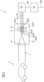
- Fig. 1 depicts a vehicle 1 comprising a digital imaging device 10, an image analysis device 151 connected to the imaging device 10 and a driving assistance device 161 connected to the image analysis device 151.
- the vehicle 1 may be a car and the imaging device 10 may be a digital camera.
- the imaging device 10 is configured to image an environment of the vehicle and to capture a traffic scene 5, for example in front of the vehicle 1. Electromagnetic radiation 7 incident from the scene 5 is imaged by imaging optics 19 of the imaging device 10 onto a sensor device of the imaging device 10.
- the sensor device comprises an imaging sensor 12 and a color filter array 14, wherein the color filter array 14 is arranged between the imaging sensor 12 and the optics 19 of the imaging device 10.
- the sensor device comprises several logical pixels 20.
- Each logical pixel 20 comprises several photosites 21 of the imaging sensor 12 and corresponding filter elements 25 of the color filter array 14.
- the imaging device 10 comprises a separate color channel 16, 17, 18 for each individual primary color of the filter elements 25 associated with the individual pixels 20.
- the color filter array 14 comprises, for each pixel 20, a first filter element having a first primary color, two second filter elements each heaving a second primary color and a third filter element having a third primary color. Consequently, the imaging device 10 comprises a first output channel 16 for the first primary color, a second output channel 17 for the second primary color and a third output channel 18 for the third primary color.
- the color filter array 14 may, for example, be configured as a RYYCy filter array so that the first color corresponds to red, the second color corresponds to yellow and the third color corresponds to cyan.
- the imaging device 10 is configured to generate output data comprising an output value for each individual color channel 16, 17, 18, that represent the intensity of the electromagnetic radiation 7 recorded by the photosites 21 associated with the individual color channels 16, 17, 18.
- the color values are received by the image analysis device 151, which is configured to implement an image analysis algorithm to extract image information 152 from the output data of the imaging device 10 by performing image analysis, such as object recognition, vehicle detection, motion detection or the like.
- the image information 152 is received by the driving assistance device 161 and the driving assistance device 161 is configured to implement a control algorithm to generate control data 162 used to control the driving behavior of the vehicle 1.
- the driving assistance device 161 is configured as an advanced driver assistance device.
- Fig. 2 depicts a simulation system 100 and an imaging device simulation module 149 for developing and evaluating the image analysis algorithm and the control algorithm.
- the imaging device simulation module 149 is configured to simulate the color perception process of the imaging device 10 and contains a model 110 representing the imaging device 10.
- the imaging device simulation module 149 and the model 110 comprise an input channel 112 for receiving input data and output channels 115 for providing output data, wherein the output channels 115 correspond to the individual output channels 16, 17, 18 of the digital imaging device 10.
- the simulation system 100 comprises an image analysis module 150, a driving assistance module 160 and a vehicle simulation module 170.
- the vehicle simulation module 170 is configured to generate a stream of images 30 that represent the traffic scene 5 to be captured by the simulated digital imaging device 10 as simulation output data 172.
- Each image 30 is provided in an input color space and fed to the imaging device simulation module 149 via the input channel 112.
- the output data 115 generated by the imaging device simulation module 149 is fed to the image analysis module 150 that implements the image analysis algorithm and extracts the image information 152 from the output data of the imaging device simulation module 149.
- the output data 115 is provided in an output color space that corresponds to a color space defined by the primary colors of the color filter array 14.
- the image information 152 is received by the driving assistance module 160 that implements the control algorithm and generates the control data 162 for controlling the behavior of the simulated vehicle 10.
- the control data 162 are fed back to the vehicle simulation module 170, which computes the reaction of the simulated vehicle 1 to the control data 162 and the corresponding change in the images 30 fed to the imaging device simulation module 149.
- Fig. 3 depicts a computer implemented method 300 executed by the simulation system 100 and the imaging device simulation module 149.
- the method 300 comprises a step of measuring 301 a spectral sensitivity for each output channel 16, 17, 18 of the digital imaging device 10.
- the method 300 further comprises a step of obtaining 305 the image 30 as the simulation output data 172 from the vehicle simulation module 170 and a step of providing 310 the image 30 via the input channel 112 to the imaging device simulation module 149.
- the image 30 is specified in an input color space that is given by sRGB color space, so that individual pixel data of the image 30 each comprise a color stimulus value R for the red channel of the input color space, a color stimulus value B for the blue channel and a color stimulus value G for the green channel of the input color space.
- the method 300 comprises a step of converting 315 the image 30 from the input color space to an intermediate color space, whereby the intermediate color space is given by CIE 1931 xyY color space.
- the method 300 further comprises a step of determining 320 a luminance value of the pixel data, which is given by the color stimulus value Y of the representation of the pixel data in the CIE 1931 xyY color space.
- the method 300 further comprises a step of checking 330, whether at least one spectral color can be assigned to the pixel data, by checking whether the color locus of the pixel data corresponds to a greyscale value. It is decided that the color locus corresponds to a greyscale value if each color stimulus value R, G, B of the pixel data exceeds a first threshold amounting to 130 and if differences between the individual color stimulus values R, G, B and the median value of the color stimulus values R, G, B of the pixel data are each below a second threshold amounting to 50, wherein the individual color stimulus values R, G, B range between a minimum value of 0 and a maximum value of 255. If the color locus of the pixel data corresponds to a greyscale value, it is decided that no spectral color can be assigned to the pixel data, otherwise, it is decided that at least one spectral color can be assigned to the pixel data.
- the method 300 comprises a step of calculating 341 a color independent output value for each color channel 16, 17, 18 of the imaging device 10.
- the method 300 comprises a step of providing 351 the calculated color independent output values c indep ( i ) of the pixel data as output data 125 of the pixel 20 of the imaging device 10.
- the method 300 comprises a step of checking 332, whether a dominant spectral color can be associated with the pixel data and a step of checking 334, whether two spectral colors can be assigned to the pixel data.
- it is checked in these steps 332, 334 for each pixel data, whether, in a chromaticity diagram 50 that represents the x chromaticity coordinate 35 and the y chromaticity coordinate 36 of the CIE 1931 xyY color space, an extrapolation 37 from a white point 52 of the diagram 50 through a color locus 132 of the pixel data intersects a spectral locus 54 or a purple line 56 of the chromaticity diagram 50.
- the white point 52 is thereby given by the D65 white point.
- the extrapolation 37 intersects the purple line 56 if the color locus 132 of the pixel data lies in a purple region 58 that is bounded by the purple line 56 and straight lines extending between the white point 52 and the ends of the purple line 56. Otherwise, the extrapolation 37 intersects the spectral locus 54 of the chromaticity diagram 50.
- the method 300 then comprises the step of assigning 339 two spectral colors to the pixel data, whereby a first spectral color is given by a spectral color corresponding to sRGB red and a second spectral color is given by a spectral color corresponding to sRGB blue. Consequently, for each output channel 16, 17, 18, the corresponding spectral sensitivity is evaluated at the first spectral color yielding a first spectral sensitivity value and at the second spectral color yielding a second spectral sensitivity value.
- the method 300 then comprises a step of assigning 337 the dominant spectral color to the pixel data.
- the dominant spectral color is given by chromaticity coordinates of an intersection 39 of the extrapolation 37 with the spectral locus 54. In this case, for each output channel 16, 17, 18, the corresponding spectral sensitivities are evaluated at only the dominant spectral color which yields a dominant spectral sensitivity value for each output channel 16, 17, 18.
- the dominant spectral color is therefore assigned to the pixel data by computing a straight line as the extrapolation 37 between the color locus 132 of the pixel data and the white point 52, by finding the intersection 39 of the created line and the spectral locus 54, by obtaining the x chromaticity coordinate value and the y chromaticity coordinate value of the intersection 39 as the chromaticity coordinate values of the dominant spectral color corresponding to the pixel data and by obtaining the wavelength value of the dominant spectral color by its x chromaticity coordinate value and its y chromaticity coordinate value.
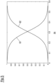
- the first argument w red ( x ) and the second argument w blue ( x ) of the linear combination of the first spectral sensitivity value css i ( ⁇ red ) and the second spectral sensitivity value css i ( ⁇ blue ) are given by a first sigmoid function w red ( x ) and a second sigmoid function w blue ( x ), wherein each sigmoid function is evaluated at the x chromaticity coordinate value x of the color locus of the pixel data.
- the dependence of the first sigmoid function 61 and the second sigmoid function 62 from the x chromaticity coordinate value 35 are shown in Fig. 5 .
- the method 300 may comprise converting the output values of the pixel data to color stimulus values of a visualization color space that is used to display the output data.
- the visualization color space is again the sRGB color space.
- the individual color stimulus values R out , G out , B out of the output data in the visualization color space are calculated as linear combinations of the output values of the output data that have been obtained from the output channels 16, 17, 18.
- the method 300 further comprises a step of providing 350 the calculated color dependent output values as color dependent output data 125 of the individual pixels 20 of the simulated digital imaging device 10.
- the method 300 further comprises a step of the image analysis module 150 obtaining 355 the image information 152 from the output data 125, a step of providing 360 the image information 152 as input data to the driving assistance module 160 and a step of the driving assistance module 160 generating 365 the control data 162 from the image information 152.
- the method 300 comprises a step of feeding back 370 the control data 162 to the vehicle simulation module 170.
Landscapes
- Engineering & Computer Science (AREA)
- Multimedia (AREA)
- Signal Processing (AREA)
- Physics & Mathematics (AREA)
- General Physics & Mathematics (AREA)
- Theoretical Computer Science (AREA)
- Color Television Image Signal Generators (AREA)
Claims (15)
- Durch einen Computer realisiertes Verfahren (300) zum Simulieren einer digitalen Bildgebungseinrichtung (10), die eine Szene (5) erfasst,wobei die Bildgebungseinrichtung (10) ein Farbfilter-Array (14) und einen Ausgangskanal (16, 17, 18) für jede Primärfarbe des Farbfilter-Arrays (14) umfasst, wobei die Bildgebungseinrichtung (10) durch ein Modell (110) beschrieben ist, das einen Eingangskanal (112) und Ausgangskanäle (115), die den einzelnen Ausgangskanälen (16, 17, 18) der digitalen Bildgebungseinrichtung (10) entsprechen, umfasst,wobei das Modell (110) ferner eine spektrale Empfindlichkeit für jeden Ausgangskanal (16, 17, 18) der digitalen Bildgebungseinrichtung (10) umfasst, wobei die spektralen Empfindlichkeiten jeweils den durch den zugehörigen Kanal der Bildgebungseinrichtung (10) detektierten relativen Betrag an Licht als Funktion einer Farbe oder Wellenlänge einer einfallenden elektromagnetischen Strahlung spezifizieren,wobei das Verfahren (300) umfasst, dass:- ein Bild (30) der Szene (5), das Pixeldaten für ein Pixel (20) der simulierten digitalen Bildgebungseinrichtung (10) enthält, über den Eingangskanal (112) bereitgestellt wird (310), wobei die Pixeldaten in einem Eingangsfarbraum spezifiziert werden, wobei sich Referenzfarbreize des Eingangsfarbraums von den Primärfarben des Farbfilter-Arrays (14) der digitalen Bildgebungseinrichtung (10) unterscheiden;- ein Luminanzwert der Pixeldaten ermittelt wird (320);- den Pixeldaten zumindest eine Spektralfarbe zugeordnet wird (337, 339);- für jeden Ausgangskanal (16, 17, 18) ein farbabhängiger Ausgangswert der Pixeldaten berechnet wird (340),wobei der berechnete farbabhängige Ausgangswert für jeden Ausgangskanal (16, 17, 18) von der spektralen Empfindlichkeit des jeweiligen Ausgangskanals (16, 17, 18), die an der zumindest einen den Pixeldaten zugeordneten Spektralfarbe bewertet wird, und dem Luminanzwert der Pixeldaten abhängt; und- die berechneten Ausgangswerte der Pixeldaten als Ausgangsdaten (125) des Pixels (20) der Bildgebungseinrichtung (10) bereitgestellt werden (350).
- Durch einen Computer realisiertes Verfahren (300) zum Simulieren einer digitalen Bildgebungseinrichtung (10), die eine Szene (5) erfasst,wobei die Bildgebungseinrichtung (10) ein Farbfilter-Array (14) und einen Ausgangskanal (16, 17, 18) für jede Primärfarbe des Farbfilter-Arrays (14) umfasst, wobei die Bildgebungseinrichtung (10) durch ein Modell (110) beschrieben ist, das einen Eingangskanal (112) und Ausgangskanäle (115), die den einzelnen Ausgangskanälen (16, 17, 18) der digitalen Bildgebungseinrichtung (10) entsprechen, umfasst,wobei das Modell ferner eine spektrale Empfindlichkeit für jeden Ausgangskanal (16, 17, 18) der digitalen Bildgebungseinrichtung (10) umfasst, wobei die spektralen Empfindlichkeiten jeweils den durch den zugehörigen Kanal der Bildgebungseinrichtung (10) detektierten relativen Betrag an Licht als Funktion einer Farbe oder Wellenlänge einer einfallenden elektromagnetischen Strahlung spezifizieren,wobei das Verfahren (300) umfasst, dass:- ein Bild (30) der Szene (5), das Pixeldaten für ein Pixel (20) der simulierten digitalen Bildgebungseinrichtung (10) enthält, über den Eingangskanal (112) bereitgestellt wird (310), wobei die Pixeldaten in einem Eingangsfarbraum spezifiziert werden, wobei sich Referenzfarbreize des Eingangsfarbraums von den Primärfarben des Farbfilter-Arrays (14) der digitalen Bildgebungseinrichtung (10) unterscheiden;- ein Luminanzwert der Pixeldaten ermittelt wird (320);- überprüft wird (330), ob den Pixeldaten zumindest eine Spektralfarbe zugeordnet werden kann,wobei das Verfahren (300) umfasst, dass, wenn den Pixeldaten die zumindest eine Spektralfarbe zugeordnet werden kann:- den Pixeldaten zumindest eine Spektralfarbe zugeordnet wird (337, 339);- für jeden Ausgangskanal (16, 17, 18) ein farbabhängiger Ausgangswert der Pixeldaten berechnet wird (340),wobei der berechnete farbabhängige Ausgangswert für jeden Ausgangskanal (16, 17, 18) von der spektralen Empfindlichkeit des jeweiligen Ausgangskanals (16, 17, 18), die an der zumindest einen den Pixeldaten zugeordneten Spektralfarbe bewertet wird, und dem Luminanzwert der Pixeldaten abhängt; und- die berechneten Ausgangswerte der Pixeldaten als Ausgangsdaten (125) des Pixels (20) der Bildgebungseinrichtung (10) bereitgestellt werden (350),wobei das Verfahren (300) umfasst, dass, wenn den Pixeldaten keine Spektralfarbe zugeordnet werden kann:- für jeden Ausgangskanal (16, 17, 18) ein farbunabhängiger Ausgangswert der Pixeldaten berechnet wird (341),wobei die farbunabhängigen Ausgangswerte als gleich berechnet werden; und- die berechneten farbunabhängigen Ausgangswerte der Pixeldaten als die Ausgangsdaten (125) des Pixels (20) der Bildgebungseinrichtung (10) bereitgestellt werden (351).
- Verfahren (300) nach Anspruch 2,wobei festgelegt wird, dass die zumindest eine Spektralfarbe den Pixeldaten zugeordnet werden kann, wenn sich ein Farbort (132) der Pixeldaten von einem Graustufenwert unterscheidet,wobei festgelegt wird, dass den Pixeldaten keine Spektralfarbe zugeordnet werden kann, wenn der Farbort (132) der Pixeldaten einem Graustufenwert entspricht.
- Verfahren (300) nach Anspruch 3,
wobei der Farbort (132) der Pixeldaten einem Graustufenwert entspricht, wenn Farbreizwerte, die die Pixeldaten in einem additiven Farbraum, beispielsweise in einem RGB-Farbraum, darstellen, jeweils einen gegebenen ersten Schwellenwert übersteigen und/oder eine Differenz zwischen den Farbreizwerten und einem Mittelwert der Farbreizwerte, beispielsweise zwischen den Farbreizwerten und einem Medianwert der Farbreizwerte, unter einem zweiten Schwellenwert liegt. - Verfahren (300) nach einem der vorstehenden Ansprüche, umfassend:- Überprüfen (332), ob den Pixeldaten eine einzelne dominante Spektralfarbe zugeordnet werden kann,
wobei, wenn den Pixeldaten die einzelne dominante Spektralfarbe zugeordnet werden kann, die für die einzelnen Ausgangskanäle (16, 17, 18) berechneten Ausgangswerte jeweils von der spektralen Empfindlichkeit des jeweiligen Ausgangskanals (16, 17, 18), die nur bei der dominanten Spektralfarbe bewertet wird, abhängen. - Verfahren (300) nach Anspruch 5,wobei das Überprüfen (332), ob die einzelne dominante Spektralfarbe den Pixeldaten zugeordnet werden kann, umfasst, dass:- überprüft wird, ob eine Extrapolation (37) von einem Weißpunkt (52) eines CIE-1931-xyY-Chromatizitätsdiagramms (50), insbesondere von dem D65-Weißpunkt (52), über einen Farbort (132) der Pixeldaten in dem Chromatizitätsdiagramm (50) den Spektralfarbenzug (54) des Chromatizitätsdiagramms (50) schneidet,wobei, wenn die Extrapolation (37) den Spektralfarbenzug (54) schneidet, festgelegt wird, dass die einzelne dominante Spektralfarbe den Pixeldaten zugeordnet werden kann, und das Verfahren (300) umfasst, dass:- eine Spektralfarbe, die dem Schnittpunkt zwischen der Extrapolation (37) und dem Spektralfarbenzug (54) entspricht, den Pixeldaten als die einzelne dominante Spektralfarbe zugeordnet wird (337).
- Verfahren (300) nach einem der vorstehenden Ansprüche, das umfasst, dass:- überprüft wird, ob den Pixeldaten zwei Spektralfarben zugeordnet werden können (334),
wobei, wenn den Pixeldaten die beiden Spektralfarben zugeordnet werden können, die für die einzelnen Ausgangskanäle (16, 17, 18) berechneten Ausgangswerte jeweils von der spektralen Empfindlichkeit des entsprechenden Ausgangskanals (16, 17, 18), die an einer ersten Spektralfarbe der beiden Spektralfarben bewertet wird, und von der spektralen Empfindlichkeit des entsprechenden Ausgangskanals (16, 17, 18), die an einer zweiten Spektralfarbe der beiden Spektralfarben bewertet wird, abhängen. - Verfahren (300) nach Anspruch 7,wobei das Überprüfen (334), ob die beiden Spektralfarben den Pixeldaten zugeordnet werden können, umfasst, dass:- überprüft wird (336), ob eine Extrapolation (37) von einem Weißpunkt (52) eines CIE-1931-xyY-Chromatizitätsdiagramms (50), insbesondere von dem D65-Weißpunkt (52), über einen Farbort (132) der Pixeldaten in dem Chromatizitätsdiagramm (50) die Violettlinie (56) des Chromatizitätsdiagramms (50) schneidet,wobei, wenn die Extrapolation (37) die Violettlinie (56) schneidet, festgelegt wird, dass die beiden Spektralfarben den Pixeldaten zugeordnet werden können, und das Verfahren (300) umfasst, dass:- eine Spektralfarbe, die sRGB-Rot entspricht, den Pixeldaten als die erste Spektralfarbe zugeordnet wird (339), und- eine Spektralfarbe, die sRGB-Blau entspricht, den Pixeldaten als die zweite Spektralfarbe zugeordnet wird (339).
- Verfahren (300) nach einem der Ansprüche 7 und 8,
wobei die Ausgangswerte für die einzelnen Ausgangskanäle (16, 17, 18) jeweils von einer Linearkombination der spektralen Empfindlichkeit des entsprechenden Ausgangskanals (16, 17, 18), die an der ersten Spektralfarbe bewertet wird, und der spektralen Empfindlichkeit des entsprechenden Ausgangskanals (16, 17, 18), die an der zweiten Spektralfarbe bewertet wird, abhängen. - Verfahren (300) nach Anspruch 9,
wobei Argumente der Linearkombination durch einen x-Chromatizitätskoordinatenwert (35) des Farborts (132) der Pixeldaten in dem CIE-1931-xyY-Chromatizitätsdiagramm (50), insbesondere durch Sigmoidfunktionen (61, 62), die an dem x-Chromatizitätskoordinatenwert (35) des Farborts (132) der Pixeldaten bewertet werden, gegeben sind. - Verfahren (300) nach einem der vorstehenden Ansprüche,
wobei, wenn die zumindest eine Spektralfarbe den Pixeldaten zugeordnet werden kann, die Ausgangswerte für die einzelnen Ausgangskanäle (16, 17, 18) jeweils von einem Parameter einer gemessenen Verstärkung abhängen, der eine globale Verstärkung darstellt, die dem entsprechenden Ausgangskanal (16, 17, 18) der Bildgebungseinrichtung (10) zugehörig ist. - Verfahren (300) nach einem der vorstehenden Ansprüche, das umfasst, dass:- die spektrale Empfindlichkeit für jeden Ausgangskanal (16, 17, 18) der digitalen Bildgebungseinrichtung (10) gemessen wird,- die gemessenen spektralen Empfindlichkeiten durch Speichern dieser in einer Speichereinheit eines Computersystems, das ausgestaltet ist, um das Verfahren (300) zu realisieren, bereitgestellt werden.
- Verfahren (300) nach einem der vorstehenden Ansprüche, das umfasst, dass:- das Bild der Szene (5) als Ausgangsdaten (172) einer virtuellen Simulation der Szene (5), insbesondere einer Verkehrsszene (5), wie sie durch die digitale Bildgebungseinrichtung (10) erfasst wird, erhalten wird (305),- eine Bildinformation (152) aus den berechneten Ausgangsdaten (125) der digitalen Bildgebungseinrichtung (10) durch Durchführen einer Bildanalyse an den berechneten Ausgangsdaten (125) erhalten wird (355),- die Bildinformation (152) als Eingangsdaten für die virtuelle Simulation der Szene (5) bereitgestellt wird (360).
- Simulationssystem (100), wobei das Simulationssystem (100) ausgestaltet ist, um das durch einen Computer realisierte Verfahren (300) nach zumindest einem der Ansprüche 1 bis 13 auszuführen,
wobei das Simulationssystem (100) als Computersystem ausgestaltet ist, das eine Verarbeitungseinheit und zumindest eine Speichereinheit, die das Modell der Bildgebungseinrichtung (10) umfasst, umfasst. - Nichttransitorisches durch einen Computer lesbares Medium, das Anweisungen zur Ausführung des durch einen Computer realisierten Verfahrens nach zumindest einem der Ansprüche 1 bis 13 umfasst.
Priority Applications (3)
| Application Number | Priority Date | Filing Date | Title |
|---|---|---|---|
| EP19163209.0A EP3709623B1 (de) | 2019-03-15 | 2019-03-15 | Verfahren zur simulation einer digitalen bildgebungsvorrichtung |
| CN202010156322.0A CN111698486B (zh) | 2019-03-15 | 2020-03-09 | 用于模拟数字成像设备的方法 |
| US16/813,833 US11282241B2 (en) | 2019-03-15 | 2020-03-10 | Method for simulating a digital imaging device |
Applications Claiming Priority (1)
| Application Number | Priority Date | Filing Date | Title |
|---|---|---|---|
| EP19163209.0A EP3709623B1 (de) | 2019-03-15 | 2019-03-15 | Verfahren zur simulation einer digitalen bildgebungsvorrichtung |
Publications (2)
| Publication Number | Publication Date |
|---|---|
| EP3709623A1 EP3709623A1 (de) | 2020-09-16 |
| EP3709623B1 true EP3709623B1 (de) | 2024-08-07 |
Family
ID=65861225
Family Applications (1)
| Application Number | Title | Priority Date | Filing Date |
|---|---|---|---|
| EP19163209.0A Active EP3709623B1 (de) | 2019-03-15 | 2019-03-15 | Verfahren zur simulation einer digitalen bildgebungsvorrichtung |
Country Status (3)
| Country | Link |
|---|---|
| US (1) | US11282241B2 (de) |
| EP (1) | EP3709623B1 (de) |
| CN (1) | CN111698486B (de) |
Families Citing this family (1)
| Publication number | Priority date | Publication date | Assignee | Title |
|---|---|---|---|---|
| EP4228187B1 (de) * | 2022-02-15 | 2024-06-19 | Aptiv Technologies AG | Integritätstests für gemischte analoge digitale systeme |
Family Cites Families (20)
| Publication number | Priority date | Publication date | Assignee | Title |
|---|---|---|---|---|
| JPS5444424A (en) * | 1977-09-14 | 1979-04-07 | Sony Corp | Solid state pick up unit |
| CN1008588B (zh) * | 1985-07-01 | 1990-06-27 | Rca许可公司 | 数字信号幅度控制装置 |
| US4843456A (en) * | 1986-07-24 | 1989-06-27 | Minolta Camera Kabushiki Kaisha | White balance adjusting device for a color video camera |
| US5008739A (en) * | 1989-02-13 | 1991-04-16 | Eastman Kodak Company | Real-time digital processor for producing full resolution color signals from a multi-color image sensor |
| JP4435355B2 (ja) * | 2000-01-19 | 2010-03-17 | 株式会社キーエンス | カラー画像の変換方法、変換装置、及び記録媒体 |
| EP1875731A2 (de) * | 2004-12-01 | 2008-01-09 | Koninklijke Philips Electronics N.V. | Verfahren zur elektronischen farbbildsättigungsverarbeitung |
| JP5151075B2 (ja) * | 2005-06-21 | 2013-02-27 | ソニー株式会社 | 画像処理装置及び画像処理方法、撮像装置、並びにコンピュータ・プログラム |
| JP2008176415A (ja) * | 2007-01-16 | 2008-07-31 | Nikon Corp | 撮像装置、画像記録プログラム、画像データ記録媒体、画像処理装置および画像処理プログラム |
| US8463068B2 (en) * | 2007-08-09 | 2013-06-11 | Micron Technology, Inc. | Methods, systems and apparatuses for pixel value correction using multiple vertical and/or horizontal correction curves |
| US8593476B2 (en) * | 2008-02-13 | 2013-11-26 | Gary Demos | System for accurately and precisely representing image color information |
| US8025408B2 (en) * | 2008-07-08 | 2011-09-27 | Panasonic Corporation | Method, apparatus and program for image processing and method and apparatus for image synthesizing |
| FR2959092B1 (fr) * | 2010-04-20 | 2013-03-08 | Centre Nat Rech Scient | Traitement numerique de compensation de signaux issus de photosites d'un capteur couleur. |
| WO2012166840A2 (en) * | 2011-06-01 | 2012-12-06 | The Board Of Trustees Of The Leland Stanford Junior University | Learning of image processing pipeline for digital imaging devices |
| JP5883949B2 (ja) * | 2011-12-28 | 2016-03-15 | ドルビー ラボラトリーズ ライセンシング コーポレイション | 画像取込デバイス処理のためのスペクトル合成 |
| US8948545B2 (en) * | 2012-02-28 | 2015-02-03 | Lytro, Inc. | Compensating for sensor saturation and microlens modulation during light-field image processing |
| WO2015005974A1 (en) * | 2013-07-08 | 2015-01-15 | Unipel Technologies, LLC | Methods and systems for controlling interferometric modulators of reflective display devices |
| US10381527B2 (en) * | 2014-02-10 | 2019-08-13 | Consumer Lighting, Llc | Enhanced color-preference LED light sources using yag, nitride, and PFS phosphors |
| EP3044504B1 (de) * | 2013-09-09 | 2020-06-03 | GE Lighting Solutions, LLC | Lichtquellen mit verbesserter farbpräferenz |
| US11056005B2 (en) * | 2018-10-24 | 2021-07-06 | Waymo Llc | Traffic light detection and lane state recognition for autonomous vehicles |
| CN109413415B (zh) * | 2018-12-12 | 2024-03-29 | 清华大学苏州汽车研究院(吴江) | 一种摄像头控制器测试系统及测试方法 |
-
2019
- 2019-03-15 EP EP19163209.0A patent/EP3709623B1/de active Active
-
2020
- 2020-03-09 CN CN202010156322.0A patent/CN111698486B/zh active Active
- 2020-03-10 US US16/813,833 patent/US11282241B2/en active Active
Also Published As
| Publication number | Publication date |
|---|---|
| US11282241B2 (en) | 2022-03-22 |
| US20200294279A1 (en) | 2020-09-17 |
| EP3709623A1 (de) | 2020-09-16 |
| CN111698486B (zh) | 2023-04-07 |
| CN111698486A (zh) | 2020-09-22 |
Similar Documents
| Publication | Publication Date | Title |
|---|---|---|
| JP5882455B2 (ja) | 高解像度マルチスペクトル画像キャプチャ | |
| CN102279050B (zh) | 一种多光谱计算重构方法及系统 | |
| CN104025562A (zh) | 用于图像捕捉设备处理的谱合成 | |
| US9872004B2 (en) | On-vehicle image capture device | |
| CN110895807B (zh) | 用于评估图像的系统、运行辅助方法和工作设备 | |
| Liu et al. | Soft prototyping camera designs for car detection based on a convolutional neural network | |
| JP5697646B2 (ja) | 車両周辺監視装置 | |
| NL2037548B1 (en) | Systems and methods for underwater imagery enhancement | |
| Farrell et al. | Sensor calibration and simulation | |
| Lyu et al. | Validation of physics-based image systems simulation with 3-D scenes | |
| CN107451976A (zh) | 一种图像处理方法及装置 | |
| JP7154786B2 (ja) | 画像処理装置、画像処理方法及びプログラム | |
| JP7260937B2 (ja) | カメラテストシステムおよびカメラテスト方法 | |
| US11282241B2 (en) | Method for simulating a digital imaging device | |
| Zhang et al. | A novel systems solution for accurate colorimetric measurement through smartphone-based augmented reality | |
| Lelowicz et al. | Discussion of novel filters and models for color space conversion | |
| JP4715288B2 (ja) | 分光反射率候補算出方法、色変換方法、分光反射率候補算出装置、色変換装置、分光反射率候補算出プログラム、色変換プログラム | |
| US20240135587A1 (en) | Method of learning parameter of sensor filter and apparatus for performing the same | |
| CN109215090A (zh) | 用于计算色差的方法、装置及服务器 | |
| CN111728589B (zh) | 一种基于医学红外热成像系统的彩色图像文件形成方法 | |
| JP4692190B2 (ja) | 分光反射率推定方法、分光反射率推定装置、ならびに分光反射率推定プログラム | |
| Lyu et al. | Accurate smartphone camera simulation using 3D scenes | |
| US8149455B2 (en) | Color reproduction method using B-spline approximation | |
| JP2009188807A (ja) | 撮像方法および撮像システム | |
| JP2023546307A (ja) | 顔色素検出モデルトレーニングの方法、装置、機器及び記憶媒体 |
Legal Events
| Date | Code | Title | Description |
|---|---|---|---|
| PUAI | Public reference made under article 153(3) epc to a published international application that has entered the european phase |
Free format text: ORIGINAL CODE: 0009012 |
|
| STAA | Information on the status of an ep patent application or granted ep patent |
Free format text: STATUS: THE APPLICATION HAS BEEN PUBLISHED |
|
| AK | Designated contracting states |
Kind code of ref document: A1 Designated state(s): AL AT BE BG CH CY CZ DE DK EE ES FI FR GB GR HR HU IE IS IT LI LT LU LV MC MK MT NL NO PL PT RO RS SE SI SK SM TR |
|
| AX | Request for extension of the european patent |
Extension state: BA ME |
|
| STAA | Information on the status of an ep patent application or granted ep patent |
Free format text: STATUS: REQUEST FOR EXAMINATION WAS MADE |
|
| 17P | Request for examination filed |
Effective date: 20210316 |
|
| RBV | Designated contracting states (corrected) |
Designated state(s): AL AT BE BG CH CY CZ DE DK EE ES FI FR GB GR HR HU IE IS IT LI LT LU LV MC MK MT NL NO PL PT RO RS SE SI SK SM TR |
|
| STAA | Information on the status of an ep patent application or granted ep patent |
Free format text: STATUS: EXAMINATION IS IN PROGRESS |
|
| 17Q | First examination report despatched |
Effective date: 20220428 |
|
| RAP3 | Party data changed (applicant data changed or rights of an application transferred) |
Owner name: APTIV TECHNOLOGIES LIMITED |
|
| GRAP | Despatch of communication of intention to grant a patent |
Free format text: ORIGINAL CODE: EPIDOSNIGR1 |
|
| STAA | Information on the status of an ep patent application or granted ep patent |
Free format text: STATUS: GRANT OF PATENT IS INTENDED |
|
| RAP1 | Party data changed (applicant data changed or rights of an application transferred) |
Owner name: APTIV TECHNOLOGIES AG |
|
| INTG | Intention to grant announced |
Effective date: 20240430 |
|
| GRAS | Grant fee paid |
Free format text: ORIGINAL CODE: EPIDOSNIGR3 |
|
| GRAA | (expected) grant |
Free format text: ORIGINAL CODE: 0009210 |
|
| STAA | Information on the status of an ep patent application or granted ep patent |
Free format text: STATUS: THE PATENT HAS BEEN GRANTED |
|
| P01 | Opt-out of the competence of the unified patent court (upc) registered |
Free format text: CASE NUMBER: APP_33199/2024 Effective date: 20240604 |
|
| AK | Designated contracting states |
Kind code of ref document: B1 Designated state(s): AL AT BE BG CH CY CZ DE DK EE ES FI FR GB GR HR HU IE IS IT LI LT LU LV MC MK MT NL NO PL PT RO RS SE SI SK SM TR |
|
| REG | Reference to a national code |
Ref country code: GB Ref legal event code: FG4D |
|
| REG | Reference to a national code |
Ref country code: CH Ref legal event code: EP |
|
| REG | Reference to a national code |
Ref country code: IE Ref legal event code: FG4D |
|
| REG | Reference to a national code |
Ref country code: DE Ref legal event code: R096 Ref document number: 602019056434 Country of ref document: DE |
|
| RAP4 | Party data changed (patent owner data changed or rights of a patent transferred) |
Owner name: APTIV TECHNOLOGIES AG |
|
| REG | Reference to a national code |
Ref country code: LT Ref legal event code: MG9D |
|
| REG | Reference to a national code |
Ref country code: NL Ref legal event code: MP Effective date: 20240807 |
|
| PG25 | Lapsed in a contracting state [announced via postgrant information from national office to epo] |
Ref country code: NO Free format text: LAPSE BECAUSE OF FAILURE TO SUBMIT A TRANSLATION OF THE DESCRIPTION OR TO PAY THE FEE WITHIN THE PRESCRIBED TIME-LIMIT Effective date: 20241107 |
|
| REG | Reference to a national code |
Ref country code: AT Ref legal event code: MK05 Ref document number: 1712169 Country of ref document: AT Kind code of ref document: T Effective date: 20240807 |
|
| PG25 | Lapsed in a contracting state [announced via postgrant information from national office to epo] |
Ref country code: PT Free format text: LAPSE BECAUSE OF FAILURE TO SUBMIT A TRANSLATION OF THE DESCRIPTION OR TO PAY THE FEE WITHIN THE PRESCRIBED TIME-LIMIT Effective date: 20241209 Ref country code: NL Free format text: LAPSE BECAUSE OF FAILURE TO SUBMIT A TRANSLATION OF THE DESCRIPTION OR TO PAY THE FEE WITHIN THE PRESCRIBED TIME-LIMIT Effective date: 20240807 Ref country code: FI Free format text: LAPSE BECAUSE OF FAILURE TO SUBMIT A TRANSLATION OF THE DESCRIPTION OR TO PAY THE FEE WITHIN THE PRESCRIBED TIME-LIMIT Effective date: 20240807 Ref country code: GR Free format text: LAPSE BECAUSE OF FAILURE TO SUBMIT A TRANSLATION OF THE DESCRIPTION OR TO PAY THE FEE WITHIN THE PRESCRIBED TIME-LIMIT Effective date: 20241108 Ref country code: PL Free format text: LAPSE BECAUSE OF FAILURE TO SUBMIT A TRANSLATION OF THE DESCRIPTION OR TO PAY THE FEE WITHIN THE PRESCRIBED TIME-LIMIT Effective date: 20240807 |
|
| PG25 | Lapsed in a contracting state [announced via postgrant information from national office to epo] |
Ref country code: BG Free format text: LAPSE BECAUSE OF FAILURE TO SUBMIT A TRANSLATION OF THE DESCRIPTION OR TO PAY THE FEE WITHIN THE PRESCRIBED TIME-LIMIT Effective date: 20240807 |
|
| PG25 | Lapsed in a contracting state [announced via postgrant information from national office to epo] |
Ref country code: LV Free format text: LAPSE BECAUSE OF FAILURE TO SUBMIT A TRANSLATION OF THE DESCRIPTION OR TO PAY THE FEE WITHIN THE PRESCRIBED TIME-LIMIT Effective date: 20240807 |
|
| PG25 | Lapsed in a contracting state [announced via postgrant information from national office to epo] |
Ref country code: AT Free format text: LAPSE BECAUSE OF FAILURE TO SUBMIT A TRANSLATION OF THE DESCRIPTION OR TO PAY THE FEE WITHIN THE PRESCRIBED TIME-LIMIT Effective date: 20240807 Ref country code: IS Free format text: LAPSE BECAUSE OF FAILURE TO SUBMIT A TRANSLATION OF THE DESCRIPTION OR TO PAY THE FEE WITHIN THE PRESCRIBED TIME-LIMIT Effective date: 20241207 |
|
| PG25 | Lapsed in a contracting state [announced via postgrant information from national office to epo] |
Ref country code: HR Free format text: LAPSE BECAUSE OF FAILURE TO SUBMIT A TRANSLATION OF THE DESCRIPTION OR TO PAY THE FEE WITHIN THE PRESCRIBED TIME-LIMIT Effective date: 20240807 |
|
| PG25 | Lapsed in a contracting state [announced via postgrant information from national office to epo] |
Ref country code: ES Free format text: LAPSE BECAUSE OF FAILURE TO SUBMIT A TRANSLATION OF THE DESCRIPTION OR TO PAY THE FEE WITHIN THE PRESCRIBED TIME-LIMIT Effective date: 20240807 Ref country code: RS Free format text: LAPSE BECAUSE OF FAILURE TO SUBMIT A TRANSLATION OF THE DESCRIPTION OR TO PAY THE FEE WITHIN THE PRESCRIBED TIME-LIMIT Effective date: 20241107 |
|
| PG25 | Lapsed in a contracting state [announced via postgrant information from national office to epo] |
Ref country code: RS Free format text: LAPSE BECAUSE OF FAILURE TO SUBMIT A TRANSLATION OF THE DESCRIPTION OR TO PAY THE FEE WITHIN THE PRESCRIBED TIME-LIMIT Effective date: 20241107 Ref country code: PT Free format text: LAPSE BECAUSE OF FAILURE TO SUBMIT A TRANSLATION OF THE DESCRIPTION OR TO PAY THE FEE WITHIN THE PRESCRIBED TIME-LIMIT Effective date: 20241209 Ref country code: PL Free format text: LAPSE BECAUSE OF FAILURE TO SUBMIT A TRANSLATION OF THE DESCRIPTION OR TO PAY THE FEE WITHIN THE PRESCRIBED TIME-LIMIT Effective date: 20240807 Ref country code: NO Free format text: LAPSE BECAUSE OF FAILURE TO SUBMIT A TRANSLATION OF THE DESCRIPTION OR TO PAY THE FEE WITHIN THE PRESCRIBED TIME-LIMIT Effective date: 20241107 Ref country code: NL Free format text: LAPSE BECAUSE OF FAILURE TO SUBMIT A TRANSLATION OF THE DESCRIPTION OR TO PAY THE FEE WITHIN THE PRESCRIBED TIME-LIMIT Effective date: 20240807 Ref country code: LV Free format text: LAPSE BECAUSE OF FAILURE TO SUBMIT A TRANSLATION OF THE DESCRIPTION OR TO PAY THE FEE WITHIN THE PRESCRIBED TIME-LIMIT Effective date: 20240807 Ref country code: IS Free format text: LAPSE BECAUSE OF FAILURE TO SUBMIT A TRANSLATION OF THE DESCRIPTION OR TO PAY THE FEE WITHIN THE PRESCRIBED TIME-LIMIT Effective date: 20241207 Ref country code: HR Free format text: LAPSE BECAUSE OF FAILURE TO SUBMIT A TRANSLATION OF THE DESCRIPTION OR TO PAY THE FEE WITHIN THE PRESCRIBED TIME-LIMIT Effective date: 20240807 Ref country code: GR Free format text: LAPSE BECAUSE OF FAILURE TO SUBMIT A TRANSLATION OF THE DESCRIPTION OR TO PAY THE FEE WITHIN THE PRESCRIBED TIME-LIMIT Effective date: 20241108 Ref country code: FI Free format text: LAPSE BECAUSE OF FAILURE TO SUBMIT A TRANSLATION OF THE DESCRIPTION OR TO PAY THE FEE WITHIN THE PRESCRIBED TIME-LIMIT Effective date: 20240807 Ref country code: ES Free format text: LAPSE BECAUSE OF FAILURE TO SUBMIT A TRANSLATION OF THE DESCRIPTION OR TO PAY THE FEE WITHIN THE PRESCRIBED TIME-LIMIT Effective date: 20240807 Ref country code: BG Free format text: LAPSE BECAUSE OF FAILURE TO SUBMIT A TRANSLATION OF THE DESCRIPTION OR TO PAY THE FEE WITHIN THE PRESCRIBED TIME-LIMIT Effective date: 20240807 Ref country code: AT Free format text: LAPSE BECAUSE OF FAILURE TO SUBMIT A TRANSLATION OF THE DESCRIPTION OR TO PAY THE FEE WITHIN THE PRESCRIBED TIME-LIMIT Effective date: 20240807 |
|
| PG25 | Lapsed in a contracting state [announced via postgrant information from national office to epo] |
Ref country code: DK Free format text: LAPSE BECAUSE OF FAILURE TO SUBMIT A TRANSLATION OF THE DESCRIPTION OR TO PAY THE FEE WITHIN THE PRESCRIBED TIME-LIMIT Effective date: 20240807 Ref country code: SM Free format text: LAPSE BECAUSE OF FAILURE TO SUBMIT A TRANSLATION OF THE DESCRIPTION OR TO PAY THE FEE WITHIN THE PRESCRIBED TIME-LIMIT Effective date: 20240807 Ref country code: RO Free format text: LAPSE BECAUSE OF FAILURE TO SUBMIT A TRANSLATION OF THE DESCRIPTION OR TO PAY THE FEE WITHIN THE PRESCRIBED TIME-LIMIT Effective date: 20240807 |
|
| PG25 | Lapsed in a contracting state [announced via postgrant information from national office to epo] |
Ref country code: EE Free format text: LAPSE BECAUSE OF FAILURE TO SUBMIT A TRANSLATION OF THE DESCRIPTION OR TO PAY THE FEE WITHIN THE PRESCRIBED TIME-LIMIT Effective date: 20240807 |
|
| PG25 | Lapsed in a contracting state [announced via postgrant information from national office to epo] |
Ref country code: CZ Free format text: LAPSE BECAUSE OF FAILURE TO SUBMIT A TRANSLATION OF THE DESCRIPTION OR TO PAY THE FEE WITHIN THE PRESCRIBED TIME-LIMIT Effective date: 20240807 |
|
| PG25 | Lapsed in a contracting state [announced via postgrant information from national office to epo] |
Ref country code: SK Free format text: LAPSE BECAUSE OF FAILURE TO SUBMIT A TRANSLATION OF THE DESCRIPTION OR TO PAY THE FEE WITHIN THE PRESCRIBED TIME-LIMIT Effective date: 20240807 |
|
| REG | Reference to a national code |
Ref country code: DE Ref legal event code: R097 Ref document number: 602019056434 Country of ref document: DE |
|
| PLBE | No opposition filed within time limit |
Free format text: ORIGINAL CODE: 0009261 |
|
| STAA | Information on the status of an ep patent application or granted ep patent |
Free format text: STATUS: NO OPPOSITION FILED WITHIN TIME LIMIT |
|
| 26N | No opposition filed |
Effective date: 20250508 |
|
| PG25 | Lapsed in a contracting state [announced via postgrant information from national office to epo] |
Ref country code: SE Free format text: LAPSE BECAUSE OF FAILURE TO SUBMIT A TRANSLATION OF THE DESCRIPTION OR TO PAY THE FEE WITHIN THE PRESCRIBED TIME-LIMIT Effective date: 20240807 |
|
| PG25 | Lapsed in a contracting state [announced via postgrant information from national office to epo] |
Ref country code: MC Free format text: LAPSE BECAUSE OF FAILURE TO SUBMIT A TRANSLATION OF THE DESCRIPTION OR TO PAY THE FEE WITHIN THE PRESCRIBED TIME-LIMIT Effective date: 20240807 |
|
| REG | Reference to a national code |
Ref country code: CH Ref legal event code: H13 Free format text: ST27 STATUS EVENT CODE: U-0-0-H10-H13 (AS PROVIDED BY THE NATIONAL OFFICE) Effective date: 20251023 |
|
| PG25 | Lapsed in a contracting state [announced via postgrant information from national office to epo] |
Ref country code: LU Free format text: LAPSE BECAUSE OF NON-PAYMENT OF DUE FEES Effective date: 20250315 |
|
| REG | Reference to a national code |
Ref country code: BE Ref legal event code: MM Effective date: 20250331 |
|
| PG25 | Lapsed in a contracting state [announced via postgrant information from national office to epo] |
Ref country code: BE Free format text: LAPSE BECAUSE OF NON-PAYMENT OF DUE FEES Effective date: 20250331 |
|
| PG25 | Lapsed in a contracting state [announced via postgrant information from national office to epo] |
Ref country code: CH Free format text: LAPSE BECAUSE OF NON-PAYMENT OF DUE FEES Effective date: 20250331 |
|
| PG25 | Lapsed in a contracting state [announced via postgrant information from national office to epo] |
Ref country code: IE Free format text: LAPSE BECAUSE OF NON-PAYMENT OF DUE FEES Effective date: 20250315 |
|
| PG25 | Lapsed in a contracting state [announced via postgrant information from national office to epo] |
Ref country code: IT Free format text: LAPSE BECAUSE OF FAILURE TO SUBMIT A TRANSLATION OF THE DESCRIPTION OR TO PAY THE FEE WITHIN THE PRESCRIBED TIME-LIMIT Effective date: 20240807 |
|
| PGFP | Annual fee paid to national office [announced via postgrant information from national office to epo] |
Ref country code: GB Payment date: 20260204 Year of fee payment: 8 |
|
| PGFP | Annual fee paid to national office [announced via postgrant information from national office to epo] |
Ref country code: DE Payment date: 20260223 Year of fee payment: 8 |
|
| PGFP | Annual fee paid to national office [announced via postgrant information from national office to epo] |
Ref country code: FR Payment date: 20260205 Year of fee payment: 8 |