EP3709663B1 - Videoübertragungsverfahren und -geräte - Google Patents
Videoübertragungsverfahren und -geräte Download PDFInfo
- Publication number
- EP3709663B1 EP3709663B1 EP18884243.9A EP18884243A EP3709663B1 EP 3709663 B1 EP3709663 B1 EP 3709663B1 EP 18884243 A EP18884243 A EP 18884243A EP 3709663 B1 EP3709663 B1 EP 3709663B1
- Authority
- EP
- European Patent Office
- Prior art keywords
- video
- reference data
- data
- coding device
- segment
- Prior art date
- Legal status (The legal status is an assumption and is not a legal conclusion. Google has not performed a legal analysis and makes no representation as to the accuracy of the status listed.)
- Active
Links
Images




Classifications
-
- H—ELECTRICITY
- H04—ELECTRIC COMMUNICATION TECHNIQUE
- H04N—PICTORIAL COMMUNICATION, e.g. TELEVISION
- H04N21/00—Selective content distribution, e.g. interactive television or video on demand [VOD]
- H04N21/20—Servers specifically adapted for the distribution of content, e.g. VOD servers; Operations thereof
- H04N21/23—Processing of content or additional data; Elementary server operations; Server middleware
- H04N21/236—Assembling of a multiplex stream, e.g. transport stream, by combining a video stream with other content or additional data, e.g. inserting a URL [Uniform Resource Locator] into a video stream, multiplexing software data into a video stream; Remultiplexing of multiplex streams; Insertion of stuffing bits into the multiplex stream, e.g. to obtain a constant bit-rate; Assembling of a packetised elementary stream
- H04N21/2365—Multiplexing of several video streams
- H04N21/23655—Statistical multiplexing, e.g. by controlling the encoder to alter its bitrate to optimize the bandwidth utilization
-
- H—ELECTRICITY
- H04—ELECTRIC COMMUNICATION TECHNIQUE
- H04N—PICTORIAL COMMUNICATION, e.g. TELEVISION
- H04N21/00—Selective content distribution, e.g. interactive television or video on demand [VOD]
- H04N21/80—Generation or processing of content or additional data by content creator independently of the distribution process; Content per se
- H04N21/83—Generation or processing of protective or descriptive data associated with content; Content structuring
- H04N21/845—Structuring of content, e.g. decomposing content into time segments
- H04N21/8456—Structuring of content, e.g. decomposing content into time segments by decomposing the content in the time domain, e.g. in time segments
-
- H—ELECTRICITY
- H04—ELECTRIC COMMUNICATION TECHNIQUE
- H04L—TRANSMISSION OF DIGITAL INFORMATION, e.g. TELEGRAPHIC COMMUNICATION
- H04L1/00—Arrangements for detecting or preventing errors in the information received
- H04L1/004—Arrangements for detecting or preventing errors in the information received by using forward error control
- H04L1/0041—Arrangements at the transmitter end
-
- H—ELECTRICITY
- H04—ELECTRIC COMMUNICATION TECHNIQUE
- H04N—PICTORIAL COMMUNICATION, e.g. TELEVISION
- H04N19/00—Methods or arrangements for coding, decoding, compressing or decompressing digital video signals
- H04N19/10—Methods or arrangements for coding, decoding, compressing or decompressing digital video signals using adaptive coding
- H04N19/169—Methods or arrangements for coding, decoding, compressing or decompressing digital video signals using adaptive coding characterised by the coding unit, i.e. the structural portion or semantic portion of the video signal being the object or the subject of the adaptive coding
- H04N19/17—Methods or arrangements for coding, decoding, compressing or decompressing digital video signals using adaptive coding characterised by the coding unit, i.e. the structural portion or semantic portion of the video signal being the object or the subject of the adaptive coding the unit being an image region, e.g. an object
- H04N19/176—Methods or arrangements for coding, decoding, compressing or decompressing digital video signals using adaptive coding characterised by the coding unit, i.e. the structural portion or semantic portion of the video signal being the object or the subject of the adaptive coding the unit being an image region, e.g. an object the region being a block, e.g. a macroblock
-
- H—ELECTRICITY
- H04—ELECTRIC COMMUNICATION TECHNIQUE
- H04N—PICTORIAL COMMUNICATION, e.g. TELEVISION
- H04N21/00—Selective content distribution, e.g. interactive television or video on demand [VOD]
- H04N21/20—Servers specifically adapted for the distribution of content, e.g. VOD servers; Operations thereof
- H04N21/21—Server components or server architectures
- H04N21/218—Source of audio or video content, e.g. local disk arrays
- H04N21/2187—Live feed
-
- H—ELECTRICITY
- H04—ELECTRIC COMMUNICATION TECHNIQUE
- H04N—PICTORIAL COMMUNICATION, e.g. TELEVISION
- H04N21/00—Selective content distribution, e.g. interactive television or video on demand [VOD]
- H04N21/20—Servers specifically adapted for the distribution of content, e.g. VOD servers; Operations thereof
- H04N21/21—Server components or server architectures
- H04N21/222—Secondary servers, e.g. proxy server, cable television Head-end
-
- H—ELECTRICITY
- H04—ELECTRIC COMMUNICATION TECHNIQUE
- H04N—PICTORIAL COMMUNICATION, e.g. TELEVISION
- H04N21/00—Selective content distribution, e.g. interactive television or video on demand [VOD]
- H04N21/20—Servers specifically adapted for the distribution of content, e.g. VOD servers; Operations thereof
- H04N21/23—Processing of content or additional data; Elementary server operations; Server middleware
- H04N21/234—Processing of video elementary streams, e.g. splicing of video streams or manipulating encoded video stream scene graphs
- H04N21/2343—Processing of video elementary streams, e.g. splicing of video streams or manipulating encoded video stream scene graphs involving reformatting operations of video signals for distribution or compliance with end-user requests or end-user device requirements
-
- H—ELECTRICITY
- H04—ELECTRIC COMMUNICATION TECHNIQUE
- H04N—PICTORIAL COMMUNICATION, e.g. TELEVISION
- H04N21/00—Selective content distribution, e.g. interactive television or video on demand [VOD]
- H04N21/20—Servers specifically adapted for the distribution of content, e.g. VOD servers; Operations thereof
- H04N21/23—Processing of content or additional data; Elementary server operations; Server middleware
- H04N21/238—Interfacing the downstream path of the transmission network, e.g. adapting the transmission rate of a video stream to network bandwidth; Processing of multiplex streams
- H04N21/2383—Channel coding or modulation of digital bit-stream, e.g. QPSK modulation
-
- H—ELECTRICITY
- H04—ELECTRIC COMMUNICATION TECHNIQUE
- H04N—PICTORIAL COMMUNICATION, e.g. TELEVISION
- H04N21/00—Selective content distribution, e.g. interactive television or video on demand [VOD]
- H04N21/20—Servers specifically adapted for the distribution of content, e.g. VOD servers; Operations thereof
- H04N21/23—Processing of content or additional data; Elementary server operations; Server middleware
- H04N21/24—Monitoring of processes or resources, e.g. monitoring of server load, available bandwidth, upstream requests
- H04N21/2402—Monitoring of the downstream path of the transmission network, e.g. bandwidth available
-
- H—ELECTRICITY
- H04—ELECTRIC COMMUNICATION TECHNIQUE
- H04N—PICTORIAL COMMUNICATION, e.g. TELEVISION
- H04N21/00—Selective content distribution, e.g. interactive television or video on demand [VOD]
- H04N21/20—Servers specifically adapted for the distribution of content, e.g. VOD servers; Operations thereof
- H04N21/25—Management operations performed by the server for facilitating the content distribution or administrating data related to end-users or client devices, e.g. end-user or client device authentication, learning user preferences for recommending movies
- H04N21/262—Content or additional data distribution scheduling, e.g. sending additional data at off-peak times, updating software modules, calculating the carousel transmission frequency, delaying a video stream transmission, generating play-lists
-
- H—ELECTRICITY
- H04—ELECTRIC COMMUNICATION TECHNIQUE
- H04N—PICTORIAL COMMUNICATION, e.g. TELEVISION
- H04N21/00—Selective content distribution, e.g. interactive television or video on demand [VOD]
- H04N21/40—Client devices specifically adapted for the reception of or interaction with content, e.g. set-top-box [STB]; Operations thereof
- H04N21/43—Processing of content or additional data, e.g. demultiplexing additional data from a digital video stream; Elementary client operations, e.g. monitoring of home network or synchronising decoder's clock; Client middleware
- H04N21/437—Interfacing the upstream path of the transmission network, e.g. for transmitting client requests to a VOD server
-
- H—ELECTRICITY
- H04—ELECTRIC COMMUNICATION TECHNIQUE
- H04N—PICTORIAL COMMUNICATION, e.g. TELEVISION
- H04N21/00—Selective content distribution, e.g. interactive television or video on demand [VOD]
- H04N21/40—Client devices specifically adapted for the reception of or interaction with content, e.g. set-top-box [STB]; Operations thereof
- H04N21/43—Processing of content or additional data, e.g. demultiplexing additional data from a digital video stream; Elementary client operations, e.g. monitoring of home network or synchronising decoder's clock; Client middleware
- H04N21/44—Processing of video elementary streams, e.g. splicing a video clip retrieved from local storage with an incoming video stream or rendering scenes according to encoded video stream scene graphs
- H04N21/4402—Processing of video elementary streams, e.g. splicing a video clip retrieved from local storage with an incoming video stream or rendering scenes according to encoded video stream scene graphs involving reformatting operations of video signals for household redistribution, storage or real-time display
-
- H—ELECTRICITY
- H04—ELECTRIC COMMUNICATION TECHNIQUE
- H04N—PICTORIAL COMMUNICATION, e.g. TELEVISION
- H04N21/00—Selective content distribution, e.g. interactive television or video on demand [VOD]
- H04N21/60—Network structure or processes for video distribution between server and client or between remote clients; Control signalling between clients, server and network components; Transmission of management data between server and client, e.g. sending from server to client commands for recording incoming content stream; Communication details between server and client
- H04N21/63—Control signaling related to video distribution between client, server and network components; Network processes for video distribution between server and clients or between remote clients, e.g. transmitting basic layer and enhancement layers over different transmission paths, setting up a peer-to-peer communication via Internet between remote STB's; Communication protocols; Addressing
- H04N21/647—Control signaling between network components and server or clients; Network processes for video distribution between server and clients, e.g. controlling the quality of the video stream, by dropping packets, protecting content from unauthorised alteration within the network, monitoring of network load, bridging between two different networks, e.g. between IP and wireless
-
- H—ELECTRICITY
- H04—ELECTRIC COMMUNICATION TECHNIQUE
- H04N—PICTORIAL COMMUNICATION, e.g. TELEVISION
- H04N21/00—Selective content distribution, e.g. interactive television or video on demand [VOD]
- H04N21/60—Network structure or processes for video distribution between server and client or between remote clients; Control signalling between clients, server and network components; Transmission of management data between server and client, e.g. sending from server to client commands for recording incoming content stream; Communication details between server and client
- H04N21/63—Control signaling related to video distribution between client, server and network components; Network processes for video distribution between server and clients or between remote clients, e.g. transmitting basic layer and enhancement layers over different transmission paths, setting up a peer-to-peer communication via Internet between remote STB's; Communication protocols; Addressing
- H04N21/647—Control signaling between network components and server or clients; Network processes for video distribution between server and clients, e.g. controlling the quality of the video stream, by dropping packets, protecting content from unauthorised alteration within the network, monitoring of network load, bridging between two different networks, e.g. between IP and wireless
- H04N21/64746—Control signals issued by the network directed to the server or the client
- H04N21/64761—Control signals issued by the network directed to the server or the client directed to the server
- H04N21/64776—Control signals issued by the network directed to the server or the client directed to the server for requesting retransmission, e.g. of data packets lost or corrupted during transmission from server
Definitions
- This disclosure relates to the video transmission field, and the invention in particular relates to video transmission methods and apparatuses, and system, and a computer readable storage medium.
- the network live broadcasting means live video broadcasting performed by using a live broadcasting network.
- an anchor terminal may shoot a live video, and send the live video to a corresponding server, and then the server sends the live video to an audience terminal, so that a user to whom the audience terminal belongs watches the live video.
- both uplink and downlink of the live video are real time, and a live broadcasting network cannot cache the live video in advance.
- the user has a relatively high requirement for a delay degree and a freezing degree of the live video. Therefore, how to ensure an uplink rate and a downlink rate of the live video so as to ensure a low delay and low freezing of the live video becomes an important part of network live broadcasting.
- the live broadcasting network may include a content delivery network (English: Content Delivery Network, CDN for short).
- CDN Content Delivery Network
- the anchor terminal may send the live video to a front-end server in the CDN network, and the front-end server may forward the live video to a background storage server in the CDN network.
- the audience terminal may request the live video from another front-end server in the CDN network, and the front-end server that receives the request may obtain the live video from the background storage server, and send the live video to the audience terminal.
- the CDN network can avoid, as much as possible, bottlenecks and processes on the Internet that may affect a data transmission speed and stability, so that data is transmitted faster and more stably. Therefore, the related technology can ensure the uplink rate and the downlink rate of the live video to some extent.
- the anchor terminal In the uplink process of the live video, if a packet loss occurs, the anchor terminal needs to retransmit video data, and this easily causes freezing and a delay of the live video.
- the object of the present invention is to provide video transmission methods and apparatuses to reduce a probability that freezing and a delay occur in a live video.
- a video transmission method is provided, and is used in a video coding device in a live broadcasting network, where the live broadcasting network includes the video coding device, a video decoding device, and a plurality of front-end servers, and the method includes:
- the video coding device may encode, separately by using the t reference data sets, the target video data segment including the k data blocks, to obtain the t encoded data blocks that are in a one-to-one correspondence with the t reference data sets, where any k reference data sets in the t reference data sets and k encoded data blocks that are in a one-to-one correspondence with the any k reference data sets can construct an equation set matrix, and data of a solution matrix of the equation set matrix is data of the target video data segment.
- the video coding device may send the t first reference data groups to the video decoding device by using the n front-end servers, where each first reference data group includes one encoded data block and an encoded data set corresponding to the encoded data block, in other words, each first reference data group is one equation in an equation set corresponding to the equation set matrix.
- the video decoding device may construct an equation set matrix, and solve a solution matrix of the equation set matrix to obtain the target video data segment through decoding.
- the video coding device may send video data in an uplink process of the live video by using a plurality of paths, in other words, by using a plurality of front-end servers. This improves utilization of uplink bandwidth of the live broadcasting network, and can avoid the freezing and the delay of the live video to some extent.
- each reference data set includes k pieces of reference data that are in a one-to-one correspondence with the k data blocks, and the encoding the target video data segment by using each reference data set, to obtain t encoded data blocks that are in a one-to-one correspondence with the t reference data sets includes:
- the obtaining a target video data segment includes:
- the video coding device may obtain the video data stream at a relatively small speed. In this case, the video coding device may be incapable of obtaining the k data blocks from the video data stream quickly, causing a relatively slow encoding speed of the video coding device.
- the video coding device may pad obtained data blocks by using preset data, to obtain the k data blocks, and then encode the k data blocks obtained through padding, to improve the encoding speed.
- the target video data segment is a (p+1) th video data segment obtained by the video coding device from the video data stream, p is a positive integer greater than or equal to 1, and before the obtaining t reference data sets, the method further includes:
- the i th historical decoding difference d i in the p historical decoding differences meets:
- the determining, based on the p historical decoding differences, a value of the quantity t of reference data sets that need to be obtained includes:
- the target video data segment is the first video data segment obtained by the video coding device from the video data stream, and before the obtaining t reference data sets, the method further includes: determining, based on an average packet loss rate of the live broadcasting network, a value of the quantity t of reference data sets that need to be obtained.
- the determining, based on an average packet loss rate of the live broadcasting network, a value of the quantity t of reference data sets that need to be obtained includes:
- the video coding device determines the value of t based on the first formula or the second formula, so that it can be ensured that the video coding device sets a proper value for t, thereby avoiding a waste of network resources of the live broadcasting network and avoiding a case in which the video decoding device cannot successfully obtain the target video data segment through decoding.
- the method further includes:
- the video coding device may further retransmit the first reference data group, to ensure that the video decoding device can successfully obtain the target video data segment through decoding.
- the method before the sending t first reference data groups to the video decoding device by using n front-end servers, the method further includes:
- the determining the n front-end servers from the r front-end servers based on a data transmission rate between the video coding device and each of the r front-end servers includes:
- the sending t first reference data groups to the video decoding device by using n front-end servers includes:
- the sending t first reference data groups to the video decoding device by using n front-end servers includes:
- the video coding device may determine the n front-end servers with better network communication quality from the r front-end servers that have established communication connections to the video coding device, and send the t first reference data groups to the video decoding device by using the n front-end servers. Because the network communication quality between the video coding device and the determined n front-end servers is relatively good, the video coding device sends data at a relatively fast rate by using the n front-end servers, so that an uplink rate of the video data stream can be ensured.
- network communication quality between a front-end server with a relatively large utility value and the video coding device is relatively good, and the video coding device may send a relatively large quantity of first reference data groups to the front-end server.
- Network communication quality between a front-end server with a relatively small utility value and the video coding device is relatively poor, and to reduce a data transmission delay, the video coding device may send a relatively small quantity of first reference data groups to the front-end server.
- the method before the obtaining a target video data segment, the method further includes:
- delay is the transmission delay
- B is a data volume size of the data block
- bit_rate is a video play bit rate of the to-be-transmitted live video
- T 0 duration required to encode or decode a video data segment including k 0 data blocks whose data volume sizes are B 0
- ⁇ is a constant
- ⁇ min is a minimum value of a packet loss rate between the video coding device and each of the n front-end servers
- ⁇ is an average packet loss rate of the live broadcast
- a proper value is set for k, so that an uplink delay of the video data segment can be within the preset transmission delay range, thereby ensuring an uplink rate of the video data segment, and avoiding a phenomenon that freezing occurs very frequently or a delay is very long when an audience terminal plays the to-be-transmitted live video.
- the sending t first reference data groups to the video decoding device by using n front-end servers includes:
- a data transmission protocol used in a live broadcasting network is usually a transmission control protocol (English: Transmission Control Protocol, TCP for short), and a congestion control mechanism of the TCP protocol is additive increase multiplicative decrease (English: Additive Increase Multiplicative Decrease, AIMD for short) mechanism.
- TCP Transmission Control Protocol
- AIMD Additive Increase Multiplicative Decrease
- the AIMD mechanism when a packet loss occurs on a link, transmit windows of the link are halved. For example, when a packet loss occurs between a sending device A and a receiving device B, the AIMD mechanism halves transmit windows of the sending device A. When transmit windows are halved, a data transmission rate is relatively seriously affected.
- the live broadcasting network may transmit the video data stream based on a UDT protocol.
- the video coding device sends the a reference data packets to the video decoding device based on the UDT protocol.
- a congestion control mechanism of the UDT protocol is decreasing additive increase multiplicative decrease (English: Decreasing Additive Increase Multiplicative Decrease, DAIMD for short) mechanism.
- DAIMD Decreasing Additive Increase Multiplicative Decrease
- a transmit window may be reduced based on available bandwidth of the link, and a reduction amplitude of the transmit window is a random number between 1/8 and 1/2. Therefore, impact exerted by the packet loss on the transmission rate of the video data stream in the live broadcasting network can be reduced in comparison with that in the TCP protocol.
- each reference data packet further includes an identifier of the target video data segment and/or an identifier of a live broadcasting channel to which the to-be-transmitted live video belongs.
- another video transmission method is provided, and is used in a video decoding device in a live broadcasting network, where the live broadcasting network includes a video coding device, the video decoding device, and a plurality of front-end servers.
- the receiving first reference data groups sent by u front-end servers includes: receiving at least one reference data packet sent by the u front-end servers, where each reference data packet includes at least one first reference data group, and a format of the reference data packet is a user datagram protocol UDP-based data transmission protocol UDT format.
- the method further includes: when a quantity of first reference data groups stored in the preset storage location is less than k at the end of the second preset duration, deleting the first reference data groups stored in the preset storage location.
- the method further includes:
- the video decoding device deletes the first reference data group, a case in which reference data groups obtained by encoding other video data segments overflow from the preset storage location because the first reference data group occupies the preset storage location for excessively long time can be avoided. If the video decoding device does not delete the first reference data group and sends the current decoding difference to the video coding device, a quantity of first reference data groups subsequently retransmitted by the video coding device to the video decoding device can be reduced, thereby saving network resources.
- the method further includes: in the second preset duration, after the quantity of received first reference data groups reaches k, sending a current decoding difference to the video coding device, where the current decoding difference is 0.
- the constructing an equation set matrix based on encoded data blocks and reference data sets in the received k first reference data groups includes:
- the method further includes: storing the at least two first reference data groups in preset storage locations.
- the preset storage location may need to simultaneously store reference data groups obtained by encoding a plurality of video data segments. To avoid overflow of the reference data groups from the preset storage location due to excessively small storage space of the preset storage location, a proper storage space size may be set for preset storage space in this embodiment of this application.
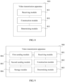
- a video transmission apparatus configured to implement the video transmission method provided in the first aspect or any optional manner of the first aspect.
- a video transmission apparatus configured to implement the video transmission method provided in the second aspect or any optional manner of the second aspect.
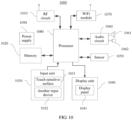
- a video transmission apparatus includes a processor and a memory; where the processor is configured to execute an instruction stored in the memory, and the processor executes the instruction to implement the video transmission method provided in the first aspect or any optional manner of the first aspect.
- a video transmission apparatus includes a processor and a memory; where the processor is configured to execute an instruction stored in the memory, and the processor executes the instruction to implement the video transmission method provided in the second aspect or any optional manner of the second aspect.
- a computer readable storage medium stores an instruction, and when the instruction runs on a processing component of a computer, the processing component is enabled to perform the video transmission method provided in the first aspect or any optional manner of the first aspect, or the processing component is enabled to perform the video transmission method provided in the second aspect or any optional manner of the second aspect.
- the video coding device encodes, separately by using the t reference data sets, the target video data segment including the k data blocks, to obtain the t encoded data blocks that are in a one-to-one correspondence with the t reference data sets, where any k reference data sets in the t reference data sets and k encoded data blocks that are in a one-to-one correspondence with the any k reference data sets can construct an equation set matrix, and data of a solution matrix of the equation set matrix is data of the target video data segment.
- the video coding device sends the t first reference data groups to the video decoding device by using the n front-end servers, where each first reference data group includes one encoded data block and an encoded data set corresponding to the encoded data block, in other words, each first reference data group is one equation in an equation set corresponding to the equation set matrix.
- each first reference data group includes one encoded data block and an encoded data set corresponding to the encoded data block, in other words, each first reference data group is one equation in an equation set corresponding to the equation set matrix.
- the video coding device may send video data in an uplink process of the live video by using a plurality of paths, in other words, by using a plurality of front-end servers. This improves utilization of uplink bandwidth of the live broadcasting network, and can avoid the freezing and the delay of the live video to some extent.
- Network live broadcasting means live video broadcasting performed by using a live broadcasting network.
- a live broadcasting network may include an anchor terminal 101, an audience terminal 102, and a content delivery network (English: Content Delivery Network, CDN for short) 103 located between the anchor terminal 101 and the audience terminal 102.
- the CDN network 103 may include a plurality of front-end servers (in FIG. 1 , only two front-end servers are used as an example: a front-end server B and a front-end server D), a centralized controller A, and a background storage server C.
- network live broadcasting may include two processes: an uplink of the live video and a downlink of the live video.
- the anchor terminal 101 may shoot the live video, and send an upload request to the centralized controller A in the CDN network 103.
- the centralized controller A may return an internet protocol (English: Internet Protocol, IP for short) address of the front-end server B in the CDN network 103 to the anchor terminal 101 based on a specific scheduling policy.
- the front-end server B is a front-end server that is in the plurality of front-end servers of the CDN network 103 and that is the closest to the anchor terminal 101 in a geographical location.
- the anchor terminal 101 may send a video data stream of the live video to the front-end server B based on the received IP address.
- the front-end server B that receives the video data stream may forward the video data stream to the background storage server C in the CDN network 103.
- the audience terminal 102 may send a viewing request to the centralized controller A.
- the centralized controller A may return an IP address of the front-end server D in the CDN network 103 to the audience terminal 102 based on a specific scheduling policy.
- the front-end server D is a front-end server that is in the plurality of front-end servers of the CDN network 103 and that is the closest to the audience terminal 102 in a geographical location.
- the audience terminal 102 may send a data stream obtaining request to the front-end server D based on the received IP address.
- the front-end server D that receives the data stream obtaining request may obtain a video data stream from the background storage server C, and send the video data stream to the audience terminal 102, so that the audience terminal 102 plays the live video based on the received video data stream.
- the anchor terminal In the uplink process of the live video, if a packet loss occurs, the anchor terminal needs to retransmit video data, and this easily causes freezing and a delay of the live video.
- the anchor terminal sends the live video to only one front-end server in the CDN network.
- This single-path video data sending manner causes relatively low uplink bandwidth utilization of the anchor terminal.
- uplink bandwidth of the live broadcasting network is usually relatively small. Based on this, the relatively low uplink bandwidth utilization of the anchor terminal causes a relatively low uplink rate of the live video, and therefore, freezing and a delay of the live video are easily caused.
- FIG. 2A is a schematic diagram of a live broadcasting network in the video transmission method.
- the live broadcasting network may include an anchor terminal 201, a CDN network 202, and an audience terminal 203.
- the anchor terminal 201 and the audience terminal 203 may be electronic devices with a video play function, such as a mobile phone or a tablet computer, and the CDN network 202 may include a plurality of front-end servers 2021, a video decoding server 2022, and a background storage server 2023.
- the anchor terminal 201 may communicate with at least two of the plurality of front-end servers 2021 in the CDN network 202 ( FIG. 2A shows only two front-end servers 2021 that communicate with the anchor terminal 201), each of the at least two front-end servers 2021 may communicate with the video decoding server 2022, and the video decoding server 2022 may communicate with the background storage server 2023.
- the audience terminal 203 may communicate with at least one of the plurality of front-end servers 2021 in the CDN network 202 ( FIG. 2A shows only one front-end server 2021 that communicates with the audience terminal 203), and each of the at least one front-end server 2021 may communicate with the background storage server 2023.
- FIG. 2B is a schematic diagram of another live broadcasting network in a video transmission method according to this application.
- An architecture of the live broadcasting network shown in FIG. 2B is basically the same as an architecture of the live broadcasting network shown in FIG. 2A .
- the live broadcasting network also includes an anchor terminal 201, a CDN network 202, and an audience terminal 203, and the CDN network 202 may also include a plurality of front-end servers 2021, a video decoding server 2022, and a background storage server 2023.
- the architecture of the live broadcasting network shown in FIG. 2B differs from the architecture of the live broadcasting network shown in FIG. 2A in that the live broadcasting network shown in FIG. 2B further includes a video coding server 204.
- the anchor terminal 201 may communicate with the video coding server 204, the video coding server 204 may communicate with at least two of the plurality of front-end servers 2021 in the CDN network 202 ( FIG. 2B shows only two front-end servers 2021 that communicate with the video coding server 204), and each of the at least two front-end servers 2021 may communicate with the video decoding server 2022.
- the CDN network 202 may further include a centralized controller.
- the centralized controller may separately communicate with the anchor terminal 201 and the audience terminal 203.
- the centralized controller may separately communicate with the video coding server 204 and the audience terminal 203.
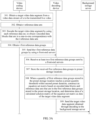
- FIG. 3A is a flowchart of a video transmission method according to an embodiment of this application.
- the video transmission method may be applied to the live broadcasting network shown in FIG. 2A or FIG. 2B .
- the video transmission method may include the following steps.
- Step 301 A video coding device obtains a target video data segment from a video data stream of a to-be-transmitted live video.
- the video coding device may be the anchor terminal 201 in FIG. 2A , or may be the video coding server 204 in FIG. 2B .
- the anchor terminal may perform a technical process of obtaining the target video data segment and encoding the target video data segment in a subsequent step
- the video coding server may perform a technical process of obtaining the target video data segment and encoding the target video data segment in a subsequent step.
- a video coding server may not need to be deployed in a live broadcasting network, so that hardware overheads can be reduced, and deployment costs of the live broadcasting network can be reduced.
- the anchor terminal does not need to perform a technical process of encoding the target video data segment. Therefore, a video coding function does not need to be added to a network live broadcasting application installed on the anchor terminal, in other words, the existing network live broadcasting application does not need to be modified. Therefore, software overheads are relatively low, and it can be ensured that the video transmission method provided in this embodiment of this application can be compatible with the existing network live broadcasting application.
- the video coding device may obtain the video data stream of the to-be-transmitted live video shot by the video coding device, and continuously obtain a plurality of video data segments from the video data stream.
- the target video data segment is one of the plurality of video data segments.
- only a process of encoding, decoding, and transmitting the target video data segment is used as an example to describe the technical solution provided in this application.
- a manner of processing another video data segment in this application is the same as that of the target video data segment.
- the video coding device may obtain the video data stream of the to-be-transmitted live video sent by the anchor terminal, and continuously obtain a plurality of video data segments from the received video data stream.
- the target video data segment is one of the plurality of video data segments.
- the video coding device may be disposed at a location, such as a base station, that is relatively close to the anchor terminal geographically, so that network communication quality between the video coding device and the anchor terminal can be ensured, thereby improving a rate at which the anchor terminal sends the video data stream to the video coding device.
- the target video data segment includes k data blocks of a same size, where k is a positive integer greater than or equal to 1.
- the size of the data block may be set based on a video data stream encapsulation format of the to-be-transmitted live video.
- a transport stream (English: Transport Stream, ts for short) encapsulation format is used as an example.
- ts encapsulation format a size of one ts packet is 188 bytes.
- a size of a maximum transmission unit (English: Maximum Transmission Unit, MTU for short) in an Ethernet is 1500 bytes, one data frame in the Ethernet can encapsulate a maximum of 7 ts packets, that is, 1316 bytes. In this case, the size of the data block may be set to 1316 bytes.
- the video coding device when the video coding device is a video coding server, the video coding device needs to receive the video data stream of the to-be-transmitted live video sent by the anchor terminal, and obtain the target video data segment from the video data stream, in other words, obtain the k data blocks from the video data stream to form the target video data segment.
- network communication quality between the anchor terminal and the video coding device is relatively poor, and therefore, a rate of transmitting the video data stream between the anchor terminal and the video coding device is relatively low.
- the video coding device cannot obtain the k data blocks from the received video data streams, in other words, obtain the target video data segment, because the video coding device cannot receive enough video data streams.
- first preset duration may be set for the video coding device.
- the video coding device may start timing after obtaining the first data block of the target video data segment from the video data stream, and monitor, in a timing process, a quantity of data blocks obtained by the video coding device.
- the video coding device may form the target video data segment by using the obtained k data blocks.
- the video coding device may pad the obtained data blocks by using preset data (for example, the preset data may be 0), to obtain k data blocks, and then the video coding device may form the target video data segment by using the k data blocks obtained through padding.
- preset data for example, the preset data may be 0
- the video coding device may form the target video data segment by using the k data blocks obtained through padding.
- the video coding device After the video coding device obtains the target video data segment, the video coding device encodes the target video data segment.
- a technical process of encoding the target video data segment may include the following steps 302 and 303.
- Step 302 The video coding device obtains t reference data sets, where t is a positive integer greater than or equal to k.
- the video coding device When encoding the target video data segment, the video coding device obtains the t reference data sets, where each reference data set includes k pieces of reference data, and the k pieces of reference data are in a one-to-one correspondence with the k data blocks included in the target video data segment.
- all the k pieces of reference data included in each of the t reference data sets may construct one reference vector, and every two of constructed t reference vectors are linearly unrelated to each other.
- an i th reference data set in the t reference data sets may include k pieces of reference data, and the k pieces of reference data are C i 1 , C i 2 , ..., C iu , ..., C ik , where C iu corresponds to a u th data block in the k data blocks included in the target video data segment.
- a j th reference data set in the t reference data sets may also include k pieces of reference data, and the k pieces of reference data are C j 1 , Cj 2 , ..., C ju , ..., C jk , where C ju corresponds to a u th data block in the k data blocks included in the target video data segment.
- the i th reference data set may construct a vector C i 1 , C i 2 , ..., C iu , C ik
- the j th reference data set may construct a vector C j 1 , C j 2 , ..., C ju , C jk , and the two vectors are linearly unrelated to each other.
- Step 303 The video coding device encodes the target video data segment by using each reference data set, to obtain t encoded data blocks that are in a one-to-one correspondence with the t reference data sets.
- step 303 is described below by using a technical process in which the video coding device encodes the target video data segment by using the i th reference data set in the t reference data sets to obtain an i th encoded data block in the t encoded data blocks as an example.
- the video coding device multiplies each piece of reference data included in the i th reference data set by a data block that is in the target video data segment and that corresponds to the i th reference data set, to obtain k products, and then the video coding device adds the k products to obtain the i th encoded data block.
- the i th reference data set may include the following k pieces of reference data: C i 1 , C i 2 , ..., C iu , C ik
- the target video data segment may include the following k data blocks: b 1 , b 2 , ..., b u , ..., b k , where C iu corresponds to b u .
- a technical process in which the video coding device encodes the target video data segments by using the t reference data sets to obtain the t encoded data blocks may be actually represented by multiplying a coefficient matrix in an equation set matrix by a solution matrix to obtain a constant-term matrix.
- the coefficient matrix includes the t reference data sets
- the solution matrix includes the k data blocks in the target video data segment
- the constant-term matrix includes the t encoded data blocks.
- Step 304 The video coding device obtains t first reference data groups.
- the video coding device After obtaining the t encoded data blocks after encoding the target video data segment, the video coding device obtains the t first reference data groups, where each first reference data group includes one encoded data block and a reference data set corresponding to the encoded data block.
- an i th first reference data group in the t first reference data groups includes the i th encoded data block a i in the t encoded data blocks and the i th reference data set in the t reference data sets
- the i th reference data set includes C i 1 , C i 2 , ..., C iu , C ik .
- Step 305 The video coding device sends the t first reference data groups to the video decoding device by using n front-end servers, where n is a positive integer greater than or equal to 1.
- the video coding device may send at least one first reference data group to each of the n front-end servers, and a sum of quantities of first reference data groups sent by the video coding device to the n front-end transmitters is equal to t.
- the video coding device may generate a reference data packets.
- Each reference data packet may include at least one first reference data group, the a reference data packets may include t first reference data groups, and a is a positive integer greater than or equal to 1.
- the video coding device may send the a reference data packets to the video decoding device by using the n front-end servers, to send the t first reference data groups to the video decoding device.
- the reference data packet may further include an identifier of the target video data segment and/or an identifier of a live broadcasting channel to which the to-be-transmitted live video belongs.
- the video decoding device may be the video decoding server 2022 in FIG. 2A or FIG. 2B .
- a format of the reference data packet may be a user datagram protocol (English: User Datagram Protocol, UDP for short)-based data transfer protocol (English: UDP-based Data Transfer Protocol, UDT for short) format.
- the video coding device may send the a reference data packets to the video decoding device based on a UDT protocol.
- a data transmission protocol used in a live broadcasting network is usually a transmission control protocol (English: Transmission Control Protocol, TCP for short), and a congestion control mechanism of the TCP protocol is additive increase multiplicative decrease (English: Additive Increase Multiplicative Decrease, AIMD for short) mechanism.
- TCP Transmission Control Protocol
- AIMD Additive Increase Multiplicative Decrease
- the AIMD mechanism when a packet loss occurs on a link, transmit windows of the link are halved. For example, when a packet loss occurs between a sending device A and a receiving device B, the AIMD mechanism halves transmit windows of the sending device A. When transmit windows are halved, a data transmission rate is relatively seriously affected.
- the live broadcasting network may transmit the video data stream based on a UDT protocol.
- the video coding device sends the a reference data packets to the video decoding device based on the UDT protocol.
- a congestion control mechanism of the UDT protocol is decreasing additive increase multiplicative decrease (English: Decreasing Additive Increase Multiplicative Decrease, DAIMD for short) mechanism.
- DAIMD Decreasing Additive Increase Multiplicative Decrease
- a transmit window may be reduced based on available bandwidth of the link, and a reduction amplitude of the transmit window is a random number between 1/8 and 1/2. Therefore, impact exerted by the packet loss on the transmission rate of the video data stream in the live broadcasting network can be reduced in comparison with that in the TCP protocol.
- the video coding device may establish communication connections to r front-end servers in a CDN network, where r is a positive integer greater than or equal to n.
- the video coding device may directly send the t first reference data groups to the video decoding device by using the r front-end servers.
- the video coding device may further determine n front-end servers with better network communication quality from the r front-end servers based on a data transmission rate between the video coding device and each of the r front-end servers, and send the t first reference data groups to the video decoding device by using the n front-end servers.
- the video coding device sends data at a relatively fast rate by using the n front-end servers, so that an uplink rate of the video data stream can be ensured.
- network communication quality between the video coding device and a front-end server may be represented by using a utility value of the front-end server.
- a larger utility value indicates better network communication quality between the front-end server and the video coding device.
- the video coding device may calculate a utility value of each of the r front-end servers, and determine the n front-end servers from the r front-end servers in descending order of utility values, and utility values of the n front-end servers are greater than a utility value of another front-end server in the r front-end servers.
- u j is a utility value of a j th front-end server in the r front-end servers
- thr j is a data transmission rate between the video coding device and the j th front-end server
- ⁇ j is a packet loss rate between the video coding device and the j th front-end server
- ⁇ is an average packet loss rate of the live broadcasting network and may be set based on an empirical value, for example, ⁇ may be set to 0.03
- ⁇ is a constant
- e is a base of a natural logarithm.
- network communication quality between the video coding device and the front-end server is usually determined by a data transmission rate and a packet loss rate that are between the video coding device and the front-end server.
- the data transmission rate may reflect available bandwidth between the video coding device and the front-end server
- the packet loss rate may reflect a path congestion degree between the video coding device and the front-end server. Therefore, in the third formula, the utility value of the front-end server may be calculated by using a data transmission rate and a packet loss rate that are between the video coding device and the front-end server.
- the packet loss rate greatly affects network communication quality between the video coding device and the front-end server, and this is because when a packet loss occurs, a transmit window of the video coding device is decreased, and the video coding device further needs to retransmit a data packet.
- a value of the constant ⁇ may be adjusted to adjust importance of the packet loss rate to the utility value. Specifically, when ⁇ j > ⁇ , a larger value of ⁇ leads to a higher rate at which the utility value of the j th front-end server decreases as ⁇ j increases.
- the video coding device may send different quantities of first reference data groups to the video decoding device by using each of the n front-end servers.
- network communication quality between a front-end server with a relatively large utility value and the video coding device is relatively good, and the video coding device may send a relatively large quantity of first reference data groups to the front-end server.
- Network communication quality between a front-end server with a relatively small utility value and the video coding device is relatively poor, and to reduce a data transmission delay, the video coding device may send a relatively small quantity of first reference data groups to the front-end server.
- the video coding device may calculate, based on the following fourth formula, a quantity of first reference data groups corresponding to each of the n front-end servers, and then the video coding device may send the corresponding quantity of first reference data groups to each front-end server, so that the front-end server sends the received first reference data groups to the video decoding device.
- y l is a quantity of first reference data groups corresponding to the first front-end server in the n front-end servers
- u l is a utility value of the first front-end server
- the video coding device may send the t first reference data groups to the video decoding device in different network connection manners.
- the different network connection manners may include network connection in a wireless fidelity (English: Wireless Fidelity, WiFi for short) manner, mobile communications network connection, fixed telephone network connection, and the like.
- uplink bandwidth of the video coding device can be increased, so that a rate at which the video coding device sends the t first reference data groups is increased, and then an uplink rate of the video data stream of the to-be-transmitted live video is increased.
- the video coding device may further detect a packet loss rate between the video coding device and each of the n front-end servers in real time.
- the video coding device may detect that a packet loss rate between the video coding device and one or more front-end servers is greater than a preset packet loss rate threshold, the video coding device may retransmit the first reference data groups.
- the preset packet loss rate threshold may be set by a person skilled in the art.
- the video coding device may obtain d reference data sets (d is a positive integer greater than or equal to 1), where k pieces of reference data included in each of the d reference data sets may construct one reference vector, every two of constructed d reference vectors are linearly unrelated to each other, and each of the constructed d reference vectors is linearly unrelated to any one of the t reference vectors constructed by using the t reference data sets. Then, the video coding device may encode the target video data segment based on a technical process similar to step 303 and step 304 by using the d reference data sets, to obtain d first reference data groups.
- the video coding device may send the d first reference data groups to the video decoding device by using one or more front-end servers with a highest utility value in the n front-end servers (a packet loss rate between the video coding device and the one or more front-end servers needs to be less than the preset packet loss rate threshold).
- Step 306 The video decoding device receives first reference data groups sent by u front-end servers, where 1 ⁇ u ⁇ n.
- the video decoding device may receive a reference data packet sent by the front-end server, and extract the first reference data group from the reference data packet.
- the video decoding device may receive the a reference data packets sent by the n front-end servers, and extract the t first reference data groups from the a reference data packets.
- a packet loss occurs between the video coding device and the n front-end servers, or a packet loss occurs between the video decoding device and the n front-end servers (in some extreme cases, all reference data packets sent by the video coding device by using a front-end server may be lost)
- a quantity of reference data packets received by the video decoding device is less than a
- a quantity of first reference data groups extracted by the video decoding device is also less than t.
- Step 307 The video decoding device stores the received first reference data groups in preset storage locations.
- the video decoding device receives reference data groups obtained by encoding a video data segment before all reference data groups obtained by encoding a previous video data segment are received. For example, when the video decoding device has received b (1 ⁇ b ⁇ t ) reference data groups in t reference data groups obtained by encoding a q th video data segment in the video data stream, the video decoding device further receives o (1 ⁇ o ⁇ t ) reference data groups in t reference data groups obtained by encoding a (q+1) th video data segment in the video data stream.
- the preset storage location may need to simultaneously store reference data groups obtained by encoding a plurality of video data segments.
- a storage space size of the preset storage location may be set based on maximum delay duration, minimum delay duration, and generation duration of the video data segment in the video data stream.
- Q is the storage space size of the preset storage location
- max( delay ) is the maximum delay duration
- the maximum delay duration is maximum duration required to send the reference data group from the video coding device to the video decoding device through the front-end server
- min( delay ) is the minimum delay duration
- the minimum delay duration is minimum duration required to send the reference data group from the video coding device to the video decoding device through the front-end server
- generate_time is the generation duration of the video data segment
- the generation duration of the video data segment is duration required by the anchor terminal to generate k data blocks
- s is a data volume size of the video data segment.
- the generation duration of the video data segment may be usually equal to play duration of the video data segment.
- the play duration of the video data segment is duration in which the audience terminal can play the to-be-transmitted live video based on the k data blocks.
- play_time is the play duration of the video data segment
- B is a data volume size of the data block
- bit_rate is a video play bit rate of the to-be-transmitted live video.
- bit_rate is the play bit rate of the to-be-transmitted live video.
- the sixth formula may be deformed as follows based on the seventh formula:
- Step 308 When a quantity of first reference data groups stored in the preset storage location reaches a preset quantity threshold within second preset duration, the video decoding device constructs an equation set matrix based on encoded data blocks and reference data sets that are in the first reference data groups stored in the preset storage location, and determines data of a calculated solution matrix of the equation set matrix as data of the target video data segment.
- the preset quantity threshold may be a quantity of first reference data groups required by the video decoding device to successfully obtain the target video data segment through decoding.
- the video decoding device can successfully obtain the target video data segment through decoding only when a quantity of received first reference data groups reaches the preset quantity threshold.
- the video coding device may send only first reference data groups whose quantity is the preset quantity threshold to the video decoding device, so that the video decoding device obtains the target video data segment through decoding based on the first reference data groups whose quantity is the preset quantity threshold and that are sent by the video coding device.
- a value of t may be equal to the preset quantity threshold.
- a non-ideal case may occur, to be specific, a packet loss may occur between the video coding device and the n front-end servers, or a packet loss may occur between the video decoding device and the n front-end servers.
- a quantity of first reference data groups that can be received by the video decoding device is less than t. Therefore, in this case, if the value of t is equal to the preset quantity threshold, the video decoding device definitely cannot successfully obtain the target video data segment through decoding. To avoid this case, the value of t is greater than the preset quantity threshold, to be specific, the video coding device sends first reference data groups that are greater than the preset quantity threshold to the video decoding device.
- a quantity of first reference data groups that can be received by the video decoding device may be still less than the preset quantity threshold.
- the video decoding device cannot successfully obtain the target video data segment through decoding. In this case, it is meaningless for the video decoding device to continue to wait for receiving the first reference data group, otherwise storage space of the preset storage location is wasted.
- the second preset duration may be set for the video decoding device.
- the video decoding device may start timing after storing the received first first reference data group in the preset storage location, and monitor, in real time in a timing process, a quantity of first reference data groups stored in the preset storage location.
- the video decoding device detects, in a period of time from the start of the timing to the second preset duration, that a quantity of first reference data groups stored in the preset storage location reaches the preset quantity threshold, the video decoding device may perform decoding based on the first reference data groups whose quantity is the preset quantity threshold, to obtain the target video data segment.
- the video decoding device may delete the first reference data group stored in the preset storage location and send a current decoding difference to the video coding device, or the video decoding device may not delete the first reference data group stored in the preset storage location, but directly send a current decoding difference to the video coding device.
- the current decoding difference is used to reflect a quantity of first reference data groups that the video decoding device lacks before successfully obtaining the target video data segment through decoding, in other words, the current decoding difference may be an absolute value of a difference between a quantity of first reference data groups (in other words, a quantity of first reference data groups received by the video decoding device) stored in the preset storage location at the end of the second preset duration and the preset quantity threshold.
- the video coding device may determine whether the current decoding difference is greater than a preset difference threshold (the preset difference threshold may be 0). When the video coding device determines that the current decoding difference is greater than the preset difference threshold, it indicates that the video decoding device cannot successfully obtain the target video data segment through decoding, and in this case, the video coding device needs to retransmit the first reference data groups to the video decoding device.
- a preset difference threshold may be 0
- the video coding device may obtain m reference data sets (m is a positive integer greater than or equal to k), where k pieces of reference data included in each of the m reference data sets may construct one reference vector, and every two of constructed m reference vectors are linearly unrelated to each other.
- the video coding device may encode the target video data segment by using each of the m reference data sets based on a technical process similar to step 303 to step 305, to obtain m encoded data blocks that are in a one-to-one correspondence with the m reference data sets, and then send m first reference data groups to the video decoding device by using q front-end servers (q is a positive integer greater than or equal to 1), where each of the m first reference data groups includes one of the m encoded data blocks and a reference data set corresponding to the encoded data block.
- q front-end servers q is a positive integer greater than or equal to 1
- the video decoding device deletes the first reference data group, a case in which reference data groups obtained by encoding other video data segments overflow from the preset storage location because the first reference data group occupies the preset storage location for excessively long time can be avoided. If the video decoding device does not delete the first reference data group, a quantity of first reference data groups subsequently retransmitted by the video coding device to the video decoding device can be reduced, thereby saving network resources.
- the video decoding device may construct the coefficient matrix of the equation set matrix by using the reference data sets whose quantity is the preset quantity threshold, where each reference data set may be used as one row of the coefficient matrix, and a rank of the row in which each reference data set is located in the coefficient matrix is the same as a rank of a row in which an encoded data block corresponding to the reference data set is located in the constant-term matrix.
- the coefficient matrix of the equation set matrix constructed by the video decoding device may be: C 11 C 12 ... C 1 u ... C 1 k C 21 C 22 ... C 2 u ... C 2 k ... ... ... ... ... ... ... C i 1 C i 2 ... C iu ... C ik ... ... ... ... ... ... C v 1 C v 2 ... C vu ... C vk .
- a rank of a row in which a reference data set C i 1 , C i 2 , ..., C iu , C ik , is located in the coefficient matrix is i
- a rank of a row in which an encoded data block a i corresponding to the reference data set C i 1 , C i 2 , ..., C iu , C ik , is located in the constant-term matrix is also i.
- the video decoding device may solve the solution matrix [ x 1 , x 2 , ..., x u , ..., x k ] T of the equation set matrix based on a Gauss-Jordan elimination (English: Gates-Jordan Elimination) algorithm.
- the solution matrix [ x 1 , x 2 , ..., x u , ..., x k ] T of the equation set matrix may be multiplied by the coefficient matrix to obtain the constant-term matrix.
- C 11 C 12 ... C 1 u ... C 1 k C 21 C 22 ... C 2 u ... C 2 k ... ... ... ... ... ... ... C i 1 C i 2 ... C iu ... C ik ... ... ... ... ... ... C v 1 C v 2 ... C vu ... C vk ⁇ x 1 x 2 ... x u ... x k a 1 a 2 ... a i ... a v .
- the solution matrix of the equation set matrix remains unchanged provided that when the video decoding device constructs the equation set matrix, a rank of a row in which the reference data set is located in the coefficient matrix is the same as a rank of a row in which an encoded data block corresponding to the reference data set is located in the constant-term matrix regardless of a sorting manner of v reference data sets in the coefficient matrix and a sorting manner of v encoded data blocks in the constant-term matrix.
- a sequence of receiving the v first reference data groups by the video decoding device is unrelated to a sequence of the k data blocks in the target video data segment finally obtained through decoding.
- out-of-order of video data streams in the to-be-transmitted live video can be avoided, so that it can be ensured that the audience terminal normally plays the to-be-transmitted live video.
- the equation set has a unique solution. Therefore, in the equation set matrix, only when both a row rank v of the coefficient matrix and a row rank v of the constant-term matrix are equal to k, the equation set matrix has a unique determined solution matrix. In other words, to ensure that the video decoding device can successfully obtain the target video data segment through decoding, a value of the preset quantity threshold v is equal to k.
- Step 309 The video decoding device sends the target video data segment obtained through decoding to the background storage server.
- the background storage server may receive a viewing request sent by the front-end server in the CDN network. After receiving the viewing request, the background storage server may send the target video data segment to the front-end server, so that the front-end server sends the target video data segment to the audience terminal.
- the video decoding device sends the target video data segment to the background storage server, and then the background storage server forwards the target video data segment to the audience terminal by using the front-end server, so that the CDN network can support a function such as playing back the live video, thereby increasing flexibility of live video playing.
- the video coding device encodes, separately by using the t reference data sets, the target video data segment including the k data blocks, to obtain the t encoded data blocks that are in a one-to-one correspondence with the t reference data sets, where any k reference data sets in the t reference data sets and k encoded data blocks that are in a one-to-one correspondence with the any k reference data sets can construct an equation set matrix, and data of a solution matrix of the equation set matrix is data of the target video data segment.
- the video coding device sends the t first reference data groups to the video decoding device by using the n front-end servers, where each first reference data group includes one encoded data block and an encoded data set corresponding to the encoded data block, in other words, each first reference data group is one equation in an equation set corresponding to the equation set matrix.
- each first reference data group includes one encoded data block and an encoded data set corresponding to the encoded data block, in other words, each first reference data group is one equation in an equation set corresponding to the equation set matrix.
- the video coding device may send video data in an uplink process of the live video by using a plurality of paths, in other words, by using a plurality of front-end servers. This improves utilization of uplink bandwidth of the live broadcasting network, and can avoid the freezing and the delay of the live video to some extent.
- the video coding device needs to set the value of t to a value greater than the preset quantity threshold (that is, k).
- the preset quantity threshold that is, k.
- the video coding device sends, to the video decoding device, excessive first reference data groups that do not work for decoding, thereby wasting network resources of the live broadcasting network; and if the value of t is set to an excessively small value, the video decoding device cannot receive first reference data groups whose quantity is the preset quantity threshold when a packet loss occurs, and consequently, the video decoding device cannot successfully obtain the target video data segment through decoding.
- the video transmission method may be applied to the live broadcasting network shown in FIG. 2A or FIG. 2B .
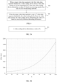
- the video transmission method may further include steps 401 and 402 shown in FIG. 4 .
- the steps 401 and 402 may be performed before step 302.
- the video coding device may continuously obtain a plurality of video data segments from the video data stream of the to-be-transmitted live video, and the target video data segment is one of the plurality of video data segments.
- the video coding device may first determine the value of t based on the average packet loss rate of the live broadcasting network before obtaining the t reference data sets.
- ⁇ is the average packet loss rate of the live broadcasting network, and may be set based on an empirical value, for example, ⁇ may be set to 0.03; ⁇ ⁇ is a rounding down operator; and min() is a minimization operation.
- Step 402 When the target video data segment is a (p+1) th (p is a positive integer greater than or equal to 1) video data segment obtained by the video coding device from the video data stream, the video coding device determines the value of t based on received p historical decoding differences.
- the video decoding device may return a decoding difference to the video coding device.
- a decoding difference returned by the video decoding device to the video coding device may be referred to as a historical decoding difference
- a decoding difference returned by the video decoding device to the video coding device for the target video data segment may be referred to as a current decoding difference.
- the video coding device may receive the p historical decoding differences sent by the video decoding device, where an i th historical decoding difference in the p historical decoding differences is used to reflect a quantity of reference data groups that the video decoding device lacks before successfully obtaining the i th video data segment through decoding at the end of the second preset duration, and the i th video data segment is an i th video data segment in p video data segments obtained by the video coding device from the video data stream before obtaining the target video data segment.
- y may be equal to the preset quantity threshold, in other words, y may be equal to k, and x is a quantity of reference data groups obtained by the video decoding device by encoding the i th video data segment.
- the video coding device may first determine the value of t based on the received p historical decoding differences before obtaining the t reference data sets.
- the video coding device encodes, separately by using the t reference data sets, the target video data segment including the k data blocks, to obtain the t encoded data blocks that are in a one-to-one correspondence with the t reference data sets, where any k reference data sets in the t reference data sets and k encoded data blocks that are in a one-to-one correspondence with the any k reference data sets can construct an equation set matrix, and data of a solution matrix of the equation set matrix is data of the target video data segment.
- the video coding device sends the t first reference data groups to the video decoding device by using the n front-end servers, where each first reference data group includes one encoded data block and an encoded data set corresponding to the encoded data block, in other words, each first reference data group is one equation in an equation set corresponding to the equation set matrix.
- each first reference data group includes one encoded data block and an encoded data set corresponding to the encoded data block, in other words, each first reference data group is one equation in an equation set corresponding to the equation set matrix.
- the video coding device may send video data in an uplink process of the live video by using a plurality of paths, in other words, by using a plurality of front-end servers. This improves utilization of uplink bandwidth of the live broadcasting network, and can avoid the freezing and the delay of the live video to some extent.
- the video coding device determines the value of t based on the first formula or the second formula, so that it can be ensured that the video coding device sets a proper value for t, thereby avoiding a waste of network resources of the live broadcasting network and avoiding a case in which the video decoding device cannot successfully obtain the target video data segment through decoding.
- the quantity k of data blocks included in the video data segment is related to an uplink delay of the video data segment, where the uplink delay is a transmission delay obtained when the video data segment is sent from the anchor terminal to the video decoding device. Therefore, in this embodiment of this application, a proper value may be set for k, so that the uplink delay falls within a preset transmission delay range.
- an embodiment of this application provides another video transmission method.
- the video transmission method may be applied to the live broadcasting network shown in FIG. 2A or FIG. 2B .
- the video transmission method may further include step 501 shown in FIG. 5A . Step 501 may be performed before step 301.
- Step 501 The video coding device determines a value of k.
- the video coding device may receive a configuration instruction sent by another device, where the configuration instruction may indicate the value of k, and the value of k indicated by the configuration instruction can enable a transmission delay to be within a preset transmission delay range; or the video coding device may determine the value of k based on a preset correspondence between a transmission delay and the quantity k of data blocks, so that a transmission delay corresponding to k falls within a preset transmission delay range.
- the “transmission delay” is the uplink delay of the video data segment. In other words, the “transmission delay” is the transmission delay obtained when the video data segment is sent from the anchor terminal to the video decoding device.
- the following describes a technical process in which the video coding device determines the value of k based on the preset correspondence between a transmission delay and the quantity k of data blocks in this embodiment of this application.
- the transmission delay may usually include: duration required by the anchor terminal to generate one video data segment, duration required by the video coding device to encode the video data segment, duration required by the video coding device to send the encoded video data segment to n front-end servers, duration required by the n front-end servers to send the encoded video data segment to the video decoding device, and duration required by the video decoding device to decode the video data segment.
- the transmission delay may further include duration required by the anchor terminal to send the video data segment to the video coding server.
- the video coding server may be usually disposed at a location, such as a base station, that is relatively close to the anchor terminal geographically, the duration required by the anchor terminal to send the video data segment to the video coding server may be ignored.
- the duration generate _time required by the anchor terminal to generate one video data segment is usually equal to play duration play_time of the video data segment, and the play duration of the video data segment is duration in which the audience terminal can play the to-be-transmitted live video based on one video data segment.
- bit_rate is a video play bit rate of the to-be-transmitted live video.
- FIG. 5B is an example schematic diagram of a correspondence between a transmission delay and the quantity k of data blocks. As shown in FIG. 5B , when it needs to be ensured that the transmission delay is less than 100 ms, a value of k may be set to 30.
- the video coding device encodes, separately by using the t reference data sets, the target video data segment including the k data blocks, to obtain the t encoded data blocks that are in a one-to-one correspondence with the t reference data sets, where any k reference data sets in the t reference data sets and k encoded data blocks that are in a one-to-one correspondence with the any k reference data sets can construct an equation set matrix, and data of a solution matrix of the equation set matrix is data of the target video data segment.
- the video coding device sends the t first reference data groups to the video decoding device by using the n front-end servers, where each first reference data group includes one encoded data block and an encoded data set corresponding to the encoded data block, in other words, each first reference data group is one equation in an equation set corresponding to the equation set matrix.
- each first reference data group includes one encoded data block and an encoded data set corresponding to the encoded data block, in other words, each first reference data group is one equation in an equation set corresponding to the equation set matrix.
- the video coding device may send video data in an uplink process of the live video by using a plurality of paths, in other words, by using a plurality of front-end servers. This improves utilization of uplink bandwidth of the live broadcasting network, and can avoid the freezing and the delay of the live video to some extent.
- a proper value is set for k, so that an uplink delay of the video data segment can be within the preset transmission delay range, thereby ensuring an uplink rate of the video data segment, and avoiding a phenomenon that freezing occurs very frequently or a delay is very long when the audience terminal plays the to-be-transmitted live video.
- FIG. 6 is a block diagram of a video transmission apparatus 600 according to an embodiment of this application.
- the video transmission apparatus 600 may be a video coding device.
- the video transmission apparatus 600 includes a first obtaining module 601, a second obtaining module 602, an encoding module 603, and a sending module 604.
- the first obtaining module 601 is configured to obtain a target video data segment, where the target video data segment is a segment of data in a video data stream of a to-be-transmitted live video, the target video data segment includes k data blocks, and k is a positive integer greater than or equal to 1.
- the second obtaining module 602 is configured to obtain t reference data sets, where each reference data set includes at least one piece of reference data, and t is a positive integer greater than k.
- the encoding module 603 is configured to encode the target video data segment by using each reference data set, to obtain t encoded data blocks that are in a one-to-one correspondence with the t reference data sets, where any k reference data sets in the t reference data sets and k encoded data blocks that are in a one-to-one correspondence with the any k reference data sets can construct an equation set matrix, and data of a solution matrix of the equation set matrix is data of the target video data segment.
- the sending module 604 is configured to send t first reference data groups to a video decoding device by using n front-end servers, where n is a positive integer greater than or equal to 1.
- Each first reference data group includes one encoded data block and a corresponding reference data set.
- Each reference data set includes k pieces of reference data that are in a one-to-one correspondence with the k data blocks, and the encoding module 603 is configured to: for each reference data set, multiply each piece of reference data included in the reference data set by a corresponding data block to obtain k products; and add the k products to obtain an encoded data block corresponding to the reference data set.
- the first obtaining module 601 is configured to: obtain the video data stream of the to-be-transmitted live video; obtain a data block from the video data stream; and in first preset duration, when a quantity of obtained data blocks is not less than k, form the target video data segment by using the obtained k data blocks; or when the quantity of obtained data blocks is less than k at the end of the first preset duration, pad the obtained data blocks by using preset data, to obtain k data blocks, and form the target video data segment by using the k data blocks obtained through padding.
- An embodiment of this application further provides another video transmission apparatus 700.
- the video transmission apparatus 700 further includes a first determining module 605, a second determining module 606, a third determining module 607, and a fourth determining module 608.
- the first determining module 605 is configured to: receive p historical decoding differences sent by the video decoding device, where the p historical decoding differences are in a one-to-one correspondence with p video data segments preceding the target video data segment in the video data stream, and each historical decoding difference is used to reflect a quantity of reference data groups that the video decoding device lacks at the end of second preset duration before successfully obtaining corresponding video data segments through decoding; and determine, based on the p historical decoding differences, a value of the quantity t of reference data sets that need to be obtained.
- the first determining module 605 is configured to:
- the target video data segment is the first video data segment obtained by the video coding device from the video data stream, and the second determining module 606 is configured to: determine, based on an average packet loss rate of a live broadcasting network, a value of the quantity t of reference data sets that need to be obtained.
- the second determining module 606 is configured to:
- the third determining module 607 is configured to:
- the third determining module 607 is configured to:
- the sending module 604 is configured to:
- the fourth determining module 608 is configured to:
- the video transmission apparatus encodes, separately by using the t reference data sets, the target video data segment including the k data blocks, to obtain the t encoded data blocks that are in a one-to-one correspondence with the t reference data sets, where any k reference data sets in the t reference data sets and k encoded data blocks that are in a one-to-one correspondence with the any k reference data sets can construct an equation set matrix, and data of a solution matrix of the equation set matrix is data of the target video data segment.
- the video coding device sends the t first reference data groups to the video decoding device by using the n front-end servers, where each first reference data group includes one encoded data block and an encoded data set corresponding to the encoded data block, in other words, each first reference data group is one equation in an equation set corresponding to the equation set matrix.
- each first reference data group includes one encoded data block and an encoded data set corresponding to the encoded data block, in other words, each first reference data group is one equation in an equation set corresponding to the equation set matrix.
- the video coding device may send video data in an uplink process of the live video by using a plurality of paths, in other words, by using a plurality of front-end servers. This improves utilization of uplink bandwidth of the live broadcasting network, and can avoid the freezing and the delay of the live video to some extent.
- FIG. 8 is a block diagram of a video transmission apparatus 800 according to an embodiment of this application.
- the video transmission apparatus 800 may be a video decoding device.
- the video transmission apparatus 800 includes a receiving module 801, a construction module 802, and a determining module 803.
- the receiving module 801 is configured to receive first reference data groups sent by u front-end servers, where each first reference data group includes an encoded data block and a corresponding reference data set, each encoded data block is obtained by a video coding device by encoding a target video data segment by using a corresponding reference data set, the target video data segment is a segment of data in a video data stream of a live video, the target video data segment includes k data blocks, the reference data set includes at least one piece of reference data, k is a positive integer greater than or equal to 1, and u is a positive integer greater than or equal to 1.
- the construction module 802 is configured to: in second preset duration, when a quantity of received first reference data groups reaches k, construct an equation set matrix based on encoded data blocks and reference data sets in the received k first reference data groups.
- the determining module 803 is configured to determine data of a calculated solution matrix of the equation set matrix as data of the target video data segment.
- construction module 802 is configured to:
- An embodiment of this application further provides another video transmission apparatus 900.
- the video transmission apparatus 900 further includes a first sending module 804, a second sending module 805, and a storage module 806.
- the first sending module 804 is configured to:
- the second sending module 805 is configured to: in the second preset duration, after the quantity of received first reference data groups reaches k, send a current decoding difference to the video coding device, where the current decoding difference is 0.
- the storage module 806 is configured to:
- the video transmission apparatus encodes, separately by using the t reference data sets, the target video data segment including the k data blocks, to obtain the t encoded data blocks that are in a one-to-one correspondence with the t reference data sets, where any k reference data sets in the t reference data sets and k encoded data blocks that are in a one-to-one correspondence with the any k reference data sets can construct an equation set matrix, and data of a solution matrix of the equation set matrix is data of the target video data segment.
- the video coding device sends the t first reference data groups to the video decoding device by using the n front-end servers, where each first reference data group includes one encoded data block and an encoded data set corresponding to the encoded data block, in other words, each first reference data group is one equation in an equation set corresponding to the equation set matrix.
- each first reference data group includes one encoded data block and an encoded data set corresponding to the encoded data block, in other words, each first reference data group is one equation in an equation set corresponding to the equation set matrix.
- the video coding device may send video data in an uplink process of the live video by using a plurality of paths, in other words, by using a plurality of front-end servers. This improves utilization of uplink bandwidth of a live broadcasting network, and can avoid the freezing and the delay of the live video to some extent.
- the terminal 1000 includes: The terminal 1000 may include parts such as an RF (Radio Frequency, radio frequency) circuit 1010, a memory 1020 that includes one or more computer readable storage media, an input unit 1030, a display unit 1040, a sensor 1050, an audio circuit 1060, a WiFi (Wireless Fidelity, wireless fidelity) module 1070, a processor 1080 including one or more processing cores, and a power supply 190.
- RF Radio Frequency, radio frequency
- a memory 1020 that includes one or more computer readable storage media
- an input unit 1030 a display unit 1040
- a sensor 1050 an audio circuit 1060
- a WiFi (Wireless Fidelity, wireless fidelity) module 1070 a processor 1080 including one or more processing cores
- a power supply 190 a person skilled in the art may understand that the terminal structure shown in FIG. 10 constitutes no limitation on the terminal, and may include more or fewer parts than those shown in the figure, or combine some parts, or have different
- the RF circuit 1010 may be configured to: receive and send a signal in an information receiving or sending process or a call process, and in particular, after receiving downlink information of a base station, send the downlink information to one or more processor 1080 for processing, and in addition, send related uplink data to the base station.
- the RF circuit 1010 includes but is not limited to an antenna, at least one amplifier, a tuner, one or more oscillators, a subscriber identity module (SIM) card, a transceiver, a coupler, an LNA (Low Noise Amplifier, low noise amplifier), a duplexer, and the like.
- the RF circuit 1010 may communicate with a network and another device through wireless communication.
- Any communications standard or protocol may be used for the wireless communication, including but not limited to GSM (Global System of Mobile communication, global system for mobile communications), GPRS (General Packet Radio Service, general packet radio service), CDMA (Code Division Multiple Access, code division multiple access), WCDMA (Wideband Code Division Multiple Access, wideband code division multiple access), LTE (Long Term Evolution, long term evolution), an email, SMS (Short Messaging Service, short message service), and the like.
- GSM Global System of Mobile communication, global system for mobile communications
- GPRS General Packet Radio Service, general packet radio service
- CDMA Code Division Multiple Access, code division multiple access
- WCDMA Wideband Code Division Multiple Access, wideband code division multiple access
- LTE Long Term Evolution, long term evolution
- SMS Short Messaging Service, short message service
- the memory 1020 may be configured to store a software program and a module, and the processor 1080 executes various functional applications and processes data by running the software program and the module that are stored in the memory 1020.
- the memory 1020 may mainly include a program storage area and a data storage area, where the program storage area may store an operating system, an application program that is required by at least one function (such as a sound playing function or an image playing function), and the like, and the data storage area may store data (such as audio data or an address book) that is created based on use of the terminal 1000, and the like.
- the memory 1020 may include a high-speed random access memory, and may further include a nonvolatile memory, such as at least one magnetic disk storage component, a flash memory component, or another volatile solid-state storage component.
- the memory 1020 may further include a memory controller, to provide the processor 1080 and the input unit 1030 with access to the memory 1020.
- the input unit 1030 may be configured to: receive input digital or character information, and produce signal input that is of a keyboard, a mouse, a joystick, optics, or a trackball and that is related to user setting and functional control.
- the input unit 1030 may include a touch-sensitive surface 1031 and another input device 1032.
- the touch-sensitive surface 1031 also referred to as a touchscreen or a touchpad, may collect a touch operation (such as an operation that a user performs on the touch-sensitive surface 1031 or near the touch-sensitive surface 1031 by using a finger, a stylus, or any other suitable object or accessory) of the user on or near the touch-sensitive surface, and drive a corresponding connection apparatus based on a preset formula.
- the touch-sensitive surface 1031 may include two parts: a touch detection apparatus and a touch controller.
- the touch detection apparatus detects a touch position of the user, detects a signal brought by a touch operation, and sends the signal to the touch controller.
- the touch controller receives touch information from the touch detection apparatus, converts the touch information into touch point coordinates, sends the touch point coordinates to the processor 1080, and can receive and execute a command sent by the processor 1080.
- the touch-sensitive surface 1031 may be implemented by a resistive, capacitive, infrared, or surface acoustic touch-sensitive surface.
- the input unit 1030 may further include another input device 1032.
- the another input device 1032 may include but is not limited to one or more of a physical keyboard, a function key (such as a volume control key or an on/off key), a trackball, a mouse, a joystick, and the like.
- the display unit 1040 may be configured to display information input by the user or information provided to the user, and various graphic user interfaces of the terminal 1000, and the graphic user interfaces may include a graphic, a text, an icon, a video, and any combination thereof.
- the display unit 1040 may include a display panel 1041.
- the display panel 1041 may be configured by using an LCD (Liquid Crystal Display, liquid crystal display), an OLED (Organic Light-Emitting Diode, organic light-emitting diode), or the like.
- the touch-sensitive surface 1031 may cover the display panel 1041.
- the touch-sensitive surface 1041 When detecting the touch operation on or near the touch-sensitive surface 1031, the touch-sensitive surface 1041 transmits the touch operation to the processor 1080 to determine a type of a touch event, and then the processor 1080 provides corresponding visual output on the display panel 1041 based on the type of the touch event.
- the touch-sensitive surface 1031 and the display panel 1041 are used as two independent components to implement input and input functions in FIG. 10 , in some embodiments, the touch-sensitive surface 1031 may be integrated with the display panel 1041 to implement the input and output functions.
- the terminal 1000 may further include at least one type of sensor 1050, such as a light sensor, a motion sensor, and another sensor.
- the light sensor may include an ambient light sensor and a proximity sensor.
- the ambient light sensor may adjust luminance of the display panel 1041 based on brightness of an ambient light.
- the proximity sensor may turn off the display panel 1041 and/or backlight when the terminal 1000 moves to an ear.
- a gravity acceleration sensor can detect a value of an acceleration in each direction (generally, three axes), can detect a value and a direction of gravity in a static mode, and can be used for an application for identifying a mobile phone gesture (such as landscape/portrait orientation switching, related games, and magnetometer gesture calibration), a function related to vibration identification (such as a pedometer and a stroke), and the like.
- a mobile phone gesture such as landscape/portrait orientation switching, related games, and magnetometer gesture calibration
- a function related to vibration identification such as a pedometer and a stroke
- sensors such as a gyroscope, a barometer, a hygrometer, a thermometer, and an infrared sensor that can be further configured on the terminal 1000, details are not described herein.
- the audio circuit 1060, a loudspeaker 1061, and a microphone 1062 can provide an audio interface between the user and the terminal 1000.
- the audio circuit 1060 may transmit, to the loudspeaker 1061, an electrical signal converted from received audio data, and the loudspeaker 1061 converts the electrical signal into a sound signal for output.
- the microphone 1062 converts a collected sound signal into an electrical signal
- the audio circuit 1060 converts the electrical signal into audio data after receiving the electrical signal and outputs the audio data to the processor 1080 for processing, and then the audio data is sent to, for example, another terminal by using the RF circuit 1010, or the audio data is output to the memory 1020 for further processing.
- the audio circuit 1060 may probably include an earplug jack, to provide an external earphone for communicating with the terminal 1000.
- WiFi is a short-distance radio transmission technology.
- the terminal 1000 uses the WiFi module 1070 to help the user receive and send an email, browse a web page, gain access to streaming media, and the like.
- the WiFi module provides the user with wireless broadband Internet access.
- the WiFi module 1070 is shown in FIG. 10 , it may be understood that the WiFi module 1070 is not a mandatory component of the terminal 1000, and may be omitted based on a requirement provided that the essence of the present invention is not changed.
- the processor 1080 may be a control center of the terminal 1000. Various interfaces and cables are used to connect to various parts of an entire mobile phone.
- the processor 1080 executes various functions of the terminal 1000 and processes data by running or executing the software program and/or module stored in the memory 1020 and by invoking data stored in the memory 1020, to perform overall monitoring on the mobile phone.
- the processor 1080 may include the one or more processing cores.
- the processor 1080 may integrate an application processor and a modem processor.
- the application processor mainly processes an operating system, a user interface, an application program, and the like, and the modem processor mainly processes wireless communication. It may be understood that the modem processor may not be integrated into the processor 1080.
- the terminal 1000 further includes the power supply 190 (such as a battery) that supplies power to the parts.
- the power supply may be logically connected to the processor 1080 by using a power management system, so that functions such as charging and discharging management and power consumption management are implemented by using the power management system.
- the power supply 190 may further include any components such as one or more direct current or alternating current power supplies, a recharging system, a power failure detection circuit, a power converter or an inverter, and a power status indicator.
- the terminal 1000 may further include a camera, a Bluetooth module and the like, and details are not described herein.
- the display unit of the terminal may be a touchscreen display, and the terminal further includes a memory and one or more programs, where the one or more programs are stored in the memory and are executed by one or more processors after being configured.
- the one or more programs includes instructions used for performing the following operations: obtaining a target video data segment, where the target video data segment is a segment of data in a video data stream of a to-be-transmitted live video, the target video data segment includes k data blocks, and k is a positive integer greater than or equal to 1; obtaining t reference data sets, where each reference data set includes at least one piece of reference data, and t is a positive integer greater than k; encoding the target video data segment by using each reference data set, to obtain t encoded data blocks that are in a one-to-one correspondence with the t reference data sets, where any k reference data sets in the t reference data sets and k encoded data blocks that are in a one-to-one correspondence with the any k reference data sets can construct an equation set matrix, and data of a solution matrix of the equation set matrix is data of the target video data segment; and sending t first reference data groups to the video decoding device by using n front-end servers, where n is a positive
- FIG. 11 is a block diagram of a video transmission apparatus 1100 according to an example.
- the apparatus 1100 may be provided as a server.
- the apparatus 1100 includes a processing component 1122, and the processing component 1122 further includes one or more processors and a memory resource represented by a memory 1132, and is configured to store an instruction, such as an application program, that can be executed by the processing component 1122.
- An application program stored in the memory 1132 may include one or more modules, where each module corresponds to a group of instructions.
- the processing component 1122 is configured to execute the instruction to perform the following method: obtaining a target video data segment, where the target video data segment is a segment of data in a video data stream of a to-be-transmitted live video, the target video data segment includes k data blocks, and k is a positive integer greater than or equal to 1; obtaining t reference data sets, where each reference data set includes at least one piece of reference data, and t is a positive integer greater than k; encoding the target video data segment by using each reference data set, to obtain t encoded data blocks that are in a one-to-one correspondence with the t reference data sets, where any k reference data sets in the t reference data sets and k encoded data blocks that are in a one-to-one correspondence with the any k reference data sets can construct an equation set matrix, and data of a solution matrix of the equation set matrix is data of the target video data segment; and sending t first reference data groups to the video decoding device by using n front-end servers, where
- the apparatus 1100 may further include a power supply component 1126 configured to execute power management of the apparatus 1100, a wired or wireless network interface 1150 configured to connect the apparatus 1100 to a network, and an input/output (I/O) interface 1158.
- the apparatus 1100 may operate an operating system stored on the memory 1132, such as Windows Server TM , Mac OS X TM , Unix TM , Linux TM , FreeBSD TM , or the like.
- An example of this application further provides a computer readable storage medium.
- the computer readable storage medium may be a non-volatile computer readable storage medium.
- the computer readable storage medium stores an instruction. When the instruction runs on a processing component of a computer, the processing component is enabled to perform the video transmission method provided in the embodiment shown in FIG. 3A .
- the program may be stored in a computer-readable storage medium.
- the storage medium may include a read-only memory, a magnetic disk, or an optical disc.
Landscapes
- Engineering & Computer Science (AREA)
- Signal Processing (AREA)
- Multimedia (AREA)
- Databases & Information Systems (AREA)
- Computer Networks & Wireless Communication (AREA)
- Computer Security & Cryptography (AREA)
- Compression Or Coding Systems Of Tv Signals (AREA)
- Two-Way Televisions, Distribution Of Moving Picture Or The Like (AREA)
Claims (20)
- Videoübertragungsverfahren, verwendet in einer Videocodiervorrichtung (201, 204) in einem Live-Rundsendenetzwerk, wobei das Live-Rundsendenetzwerk die Videocodiervorrichtung (201, 204), eine Videodecodiervorrichtung (2022) und mehrere Frontend-Server (2021) umfasst, und wobei das Verfahren Folgendes umfasst:Erhalten (301) eines Zielvideodatensegments, wobei das Zielvideodatensegment ein Segment von Daten in einem Videodatenstrom eines zu übertragenden Live-Videos ist, wobei das Zielvideodatensegment k Datenblöcke umfasst und wobei k eine positive ganze Zahl größer als oder gleich 1 ist;Erhalten (302) von t Referenzdatensätzen, wobei jeder Referenzdatensatz k Stücke von Referenzdaten umfasst, die in einer Eins-zu-Eins-Entsprechung mit den k Datenblöcken sind, und wobei t eine positive ganze Zahl größer als k ist;Codieren (303) des Zielvideodatensegments unter Verwendung der einzelnen Referenzdatensätze zum Erhalten von t codierten Datenblöcken, die in einer Eins-zu-Eins-Entsprechung mit den t Referenzdatensätzen sind, wobei beliebige k Referenzdatensätze in den t Referenzdatensätzen und k codierte Datenblöcke, die in einer Eins-zu-Eins-Entsprechung mit beliebigen k Referenzdatensätzen sind, eine Gleichungsmengenmatrix konstruieren können, und wobei Daten einer Lösungsmatrix der Gleichungsmengenmatrix Daten des Zielvideodatensegments sind; undSenden (304, 305) von t ersten Referenzdatengruppen an die Videodecodiervorrichtung (2022) unter Verwendung von n Frontend-Servern, wobei n eine positive ganze Zahl größer als oder gleich 1 ist; wobeijede erste Referenzdatengruppe einen codierten Datenblock und einen entsprechenden Referenzdatensatz umfasst; wobeidas Codieren des Zielvideodatensegments unter Verwendung jedes Referenzdatensatzes zum Erhalten von t codierten Datenblöcken, die in einer Eins-zu-Eins-Entsprechung mit den t Referenzdatensätzen sind, Folgendes umfasst:
für jeden Referenzdatensatz, Multiplizieren jedes Stückes von in dem Referenzdatensatz enthaltenen Referenzdaten mit einem entsprechenden Datenblock zum Erhalten von k Produkten; und
Addieren der k Produkte zum Erhalten eines codierten Datenblocks entsprechend dem Referenzdatensatz. - Verfahren nach Anspruch 1, wobei das Erhalten (301) eines Zielvideodatensegments Folgendes umfasst:
Erhalten des Videodatenstroms des zu übertragenden Live-Videos;Erhalten eines ersten Datenblocks aus dem Videodatenstrom;nach Erhalten des ersten Datenblocks, Überwachen, in einer ersten voreingestellten Dauer, die für die Videocodiervorrichtung festgelegt ist, einer Quantität von Datenblöcken, die durch die Videocodiervorrichtung erhalten werden, undwenn in der ersten voreingestellten Dauer eine Quantität von erhaltenen Datenblöcken k erreicht, Bilden des Zielvideodatensegments durch Verwenden der erhaltenen k Datenblöcke; oderwenn die Quantität von erhaltenen Datenblöcken am Ende der ersten voreingestellten Dauer kleiner als k ist, Auffüllen der erhaltenen Datenblöcke durch Verwenden von voreingestellten Daten zum Erhalten von k Datenblöcken, und Bilden des Zielvideodatensegments durch Verwenden der durch Auffüllen erhaltenen k Datenblöcke, - Verfahren nach Anspruch 1, wobei das Zielvideodatensegment ein (p+1)-tes Videodatensegment ist, das durch die Videocodiervorrichtung (201, 204) aus dem Videodatenstrom erhalten wurde, p eine positive ganze Zahl größer als oder gleich 1 ist, und wobei, vor dem Erhalten (302) von t Referenzdatensätzen das Verfahren ferner Folgendes umfasst:Empfangen von p historischen Decodierdifferenzen, gesendet durch die Videodecodiervorrichtung (2022), wobei die entsprechende historische Decodierdifferenz eine Decodierdifferenz ist, die durch die Videodecodiervorrichtung an die Videocodiervorrichtung zurückgegeben wird, bevor die Videocodiervorrichtung das Zielvideodatensegment codiert, und wobei die p historischen Decodierdifferenzen in einer Eins-zu-Eins-Entsprechung mit p Videodatensegmenten sind, die dem Zielvideodatensegment im Videodatenstrom vorausgehen, und wenn eine Quantität von empfangenen ersten Referenzdatengruppen kleiner als eine voreingestellte Quantitätsschwelle am Ende einer zweiten voreingestellten Dauer ist, sendet die Videodecodiervorrichtung, als die entsprechende historische Decodierdifferenz, eine Decodierdifferenz an die Videocodiervorrichtung, die der Absolutwert einer Differenz zwischen der Quantität von ersten Referenzdatengruppen, empfangen durch die Videodecodiervorrichtung am Ende der zweiten voreingestellten Dauer, und der voreingestellten Quantitätsschwelle ist; undBestimmen (402), basierend auf den p historischen Decodierdifferenzen und einer ersten Formel, eines Werts der Quantität t von Referenzdatensätzen, die erhalten werden müssen.
- Verfahren nach Anspruch 3, wobei eine i-te historische Decodierdifferenz di in den p historischen Decodierdifferenzen Folgendes erfüllt:
wenn die Videodecodiervorrichtung (2022), in der zweiten voreingestellten Dauer, durch Decodieren erfolgreich ein i-tes Videodatensegment erhält, das im Videodatenstrom ist und das der i-ten historischen Decodierdifferenz entspricht, di = 0; und wenn die Videodecodiervorrichtung (2022) das i-te Videodatensegment durch Decodieren am Ende der zweiten voreingestellten Dauer nicht erhält, di = y - x, wobei
y die voreingestellte Quantitätsschwelle von ersten Referenzdatengruppen ist, die durch die Videodecodiervorrichtung (2022) erfordert wird, um das i-te Videodatensegment durch Decodieren erfolgreich zu erhalten, x eine Quantität von ersten Referenzdatengruppen entsprechend dem i-ten Videodatensegment ist, die am Ende der zweiten voreingestellten Dauer durch die Videodecodiervorrichtung erhalten werden, und 1 ≤ i ≤ p. - Verfahren nach Anspruch 3 oder 4, wobei das Bestimmen, basierend auf den p historischen Decodierdifferenzen und der ersten Formel, des Werts der Quantität t von Referenzdatensätzen, die erhalten werden müssen, Folgendes umfasst:Berechnen, basierend auf den p historischen Decodierdifferenzen und der ersten Formel, des Werts der Quantität t von Referenzdatensätzen, die erhalten werden müssen, wobei die erste Formel wie folgt ist:
 Fi = di / k und
- Verfahren nach Anspruch 1, wobei das Zielvideodatensegment das erste Videodatensegment ist, das durch die Videocodiervorrichtung (201, 204) aus dem Videodatenstrom erhalten wurde, und wobei, vor dem Erhalten von t Referenzdatensätzen das Verfahren ferner Folgendes umfasst:
Bestimmen (401), basierend auf einer durchschnittlichen Paketverlustrate des Live-Rundsendenetzwerks, eines Werts der Quantität t von Referenzdatensätzen, die erhalten werden müssen. - Verfahren nach Anspruch 6, wobei das Bestimmen (401), basierend auf einer durchschnittlichen Paketverlustrate des Live-Rundsendenetzwerks, eines Werts der Quantität t von Referenzdatensätzen, die erhalten werden müssen, Folgendes umfasst:
Berechnen, basierend auf der durchschnittlichen Paketverlustrate des Live-Rundsendenetzwerks und einer zweiten Formel, des Werts der Quantität t von Referenzdatensätzen, die erhalten werden müssen, wobei die zweite Formel wie folgt ist:
- Verfahren nach Anspruch 1, wobei vor dem Senden von t ersten Referenzdatengruppen an die Videodecodiervorrichtung unter Verwendung von n Frontend-Servern, das Verfahren ferner Folgendes umfasst:
Bestimmen von r Frontend-Servern, die Kommunikationsverbindungen mit der Videocodiervorrichtung hergestellt haben, wobei r eine positive ganze Zahl größer als oder gleich n ist; und
Bestimmen der n Frontend-Server aus den r Frontend-Servern basierend auf einer Datenübertragungsrate zwischen der Videocodiervorrichtung und jedem der r Frontend-Server, wobei die Kommunikationsqualität zwischen den n Frontend-Servern und der Videocodiervorrichtung besser als die Kommunikationsqualität zwischen einem anderen Frontend-Server und der Videocodiervorrichtung ist. - Verfahren nach Anspruch 8, wobei das Bestimmen der n Frontend-Server aus den r Frontend-Servern basierend auf einer Datenübertragungsrate zwischen der Videocodiervorrichtung und jedem der r Frontend-Server Folgendes umfasst:Berechnen eines Gebrauchswerts jedes Frontend-Servers basierend auf einer dritten Formel und der Datenübertragungsrate zwischen der Videocodiervorrichtung und jedem der r Frontend-Server, wobei die dritte Formel wie folgt ist:
 Bestimmen der n Frontend-Server aus den r Frontend-Servern in absteigender Reihenfolge hinsichtlich der Gebrauchswerte.
 - Verfahren nach Anspruch 9, wobei das Senden von t ersten Referenzdatengruppen an die Videodecodiervorrichtung unter Verwendung von n Frontend-Servern Folgendes umfasst:Bestimmen, basierend auf einer vierten Formel, einer Quantität von ersten Referenzdatengruppen entsprechend jedem der n Frontend-Server, wobei die vierte Formel wie folgt ist:
 yl eine Quantität von ersten Referenzdatengruppen entsprechend dem jeweiligen Frontend-Server in den n Frontend-Servern ist, ul ein Gebrauchswert des jeweiligen Frontend-Servers ist,
 Senden einer entsprechenden Quantität von ersten Referenzdatengruppen an jeden Frontend-Server, sodass der Frontend-Server die empfangenen ersten Referenzdatengruppen an die Videodecodiervorrichtung sendet.
 - Verfahren nach Anspruch 1, wobei vor dem Erhalten eines Zielvideodatensegments das Verfahren ferner Folgendes umfasst:Bestimmen der Quantität k von Datenblöcken im Zielvideosegment basierend auf einer voreingestellten Entsprechung zwischen einer Übertragungsverzögerung und einer Quantität von Datenblöcken, sodass eine Übertragungsverzögerung entsprechend der Quantität k von Datenblöcken in einen voreingestellten Übertragungsverzögerungsbereich fällt; wobeidie Übertragungsverzögerung eine Übertragungsverzögerung ist, die besteht, wenn die Videocodiervorrichtung das Videodatensegment an die Videodecodiervorrichtung sendet.
- Videoübertragungsverfahren, verwendet in einer Videodecodiervorrichtung (2022) in einem Live-Rundsendenetzwerk, wobei das Live-Rundsendenetzwerk eine Videocodiervorrichtung (201, 204), die Videodecodiervorrichtung (2022) und mehrere Frontend-Server (2021) umfasst, und wobei das Verfahren Folgendes umfasst:Empfangen (306) von t ersten Referenzdatengruppen, gesendet durch u Frontend-Server, wobei jede erste Referenzdatengruppe einen codierten Datenblock und einen entsprechenden Referenzdatensatz in t Referenzdatensätzen umfasst,wobei jeder codierte Datenblock durch die Videocodiervorrichtung erhalten wird durch Codieren eines Zielvideodatensegments unter Verwendung eines entsprechenden Referenzdatensatzes, wobei das Zielvideodatensegment ein Segment von Daten in einem Videodatenstrom eines Live-Videos ist, das Zielvideodatensegment k Datenblöcke umfasst, der Referenzdatensatz k Stücke von Referenzdaten umfasst, die in einer Eins-zu-Eins-Entsprechung mit den k Datenblöcken sind, wobei k eine positive ganze Zahl größer als oder gleich 1 ist, t eine positive ganze Zahl größer als k ist und u eine positive ganze Zahl größer als oder gleich 1 ist;in einer zweiten voreingestellten Dauer, wenn eine Quantität von empfangenen ersten Referenzdatengruppen k erreicht, Konstruieren (308) einer Gleichungsmengenmatrix basierend auf codierten Datenblöcken und Referenzdatensätzen in den empfangenen k ersten Referenzdatengruppen; undBestimmen (308) von Daten einer berechneten Lösungsmatrix der Gleichungsmengenmatrix als Daten des Zielvideodatensegments; wobeidas Codieren des Zielvideodatensegments unter Verwendung jedes Referenzdatensatzes t codierte Datenblöcke erhält, die in einer Eins-zu-Eins-Entsprechung mit den t Referenzdatensätzen sind, und Folgendes umfasst:für jeden Referenzdatensatz, Multiplizieren jedes Stückes von in dem Referenzdatensatz enthaltenen Referenzdaten mit einem entsprechenden Datenblock zum Erhalten von k Produkten; undAddieren der k Produkte zum Erhalten eines codierten Datenblocks entsprechend dem Referenzdatensatz.
- Verfahren nach Anspruch 12, wobei das Verfahren ferner Folgendes umfasst:wenn die Quantität von empfangenen ersten Referenzdatengruppen am Ende der zweiten voreingestellten Dauer kleiner als k ist, Erhalten eines Absolutwerts einer Differenz zwischen der Quantität von empfangenen ersten Referenzdatengruppen und k; undSenden des Absolutwerts an die Videocodiervorrichtung als eine aktuelle Decodierdifferenz.
- Verfahren nach Anspruch 12, wobei das Verfahren ferner Folgendes umfasst:
in der zweiten voreingestellten Dauer, nachdem die Quantität von empfangenen ersten Referenzdatengruppen k erreicht, Senden einer aktuellen Decodierdifferenz an die Videocodiervorrichtung, wobei die aktuelle Decodierdifferenz 0 ist. - Verfahren nach Anspruch 12, wobei das Konstruieren einer Gleichungsmengenmatrix basierend auf codierten Datenblöcken und Referenzdatensätzen in den empfangenen k ersten Referenzdatengruppen Folgendes umfasst:Parsen der empfangenen k ersten Referenzdatengruppen zum Erhalten von k codierten Datenblöcken und k Referenzdatensätzen, die in einer Eins-zu-Eins-Entsprechung mit den k codierten Datenblöcken sind;Konstruieren einer Konstantenterm-Matrix der Gleichungsmengenmatrix unter Verwendung der k codierten Datenblöcke, wobei jeder codierte Datenblock als eine Zeile der Konstantenterm-Matrix verwendet wird; undKonstruieren einer Koeffizientenmatrix der Gleichungsmengenmatrix unter Verwendung der k Referenzdatensätze, wobei jeder Referenzdatensatz als eine Zeile der Koeffizientenmatrix verwendet wird, und wobei ein Rang der Zeile, in der jeder Referenzdatensatz in der Koeffizientenmatrix befindlich ist, der gleiche ist wie ein Rang einer Zeile, in der ein entsprechender codierter Datenblock in der Konstantenterm-Matrix befindlich ist.
- Verfahren nach Anspruch 12, wobei nach dem Empfangen (306) von durch u Frontend-Server gesendeten ersten Referenzdatengruppen das Verfahren ferner Folgendes umfasst:Speichern (307) der ersten Referenzdatengruppen in voreingestellten Speicherorten; wobeieine Speicherplatzgröße des voreingestellten Speicherorts basierend auf einer maximalen Verzögerungsdauer, einer minimalen Verzögerungsdauer und einer Erzeugungsdauer eines Videodatensegments im Videodatenstrom bestimmt wird, wobeidie maximale Verzögerungsdauer eine maximale Dauer ist, die für die Videocodiervorrichtung erforderlich ist, um die Referenzdatengruppe über den Frontend-Server an die Videodecodiervorrichtung zu senden, und wobei die minimale Verzögerungsdauer eine minimale Dauer ist, die für die Videocodiervorrichtung erforderlich ist, um die Referenzdatengruppe über den Frontend-Server an die Videodecodiervorrichtung zu senden.
- Verfahren nach Anspruch 16, wobei:die Speicherplatzgröße des voreingestellten Speicherorts eine sechste Formel erfüllt, und wobei die sechste Formel wie folgt ist:
 Q die Speicherplatzgröße des voreingestellten Speicherorts ist, max(Verzögerung) die maximale Verzögerungsdauer ist, min(Verzögerung) die minimale Verzögerungsdauer ist, Erzeugungszeit die Erzeugungsdauer des Videodatensegments im Videodatenstrom ist und s eine Datenvolumengröße des Videodatensegments ist.
 - Videoübertragungseinrichtung (600), verwendet in einer Videocodiervorrichtung (201, 204) in einem Live-Rundsendenetzwerk, wobei das Live-Rundsendenetzwerk die Videocodiervorrichtung (201, 204), eine Videodecodiervorrichtung (2022) und mehrere Frontend-Server (2021) umfasst, und wobei die Einrichtung Folgendes umfasst:ein erstes Erhaltemodul (601), ausgelegt zum Erhalten (301) eines Zielvideodatensegments, wobei das Zielvideodatensegment ein Segment von Daten in einem Videodatenstrom eines zu übertragenden Live-Videos ist, wobei das Zielvideodatensegment k Datenblöcke umfasst und wobei k eine positive ganze Zahl größer als oder gleich 1 ist;ein zweites Erhaltemodul (602), ausgelegt zum Erhalten (302) von t Referenzdatensätzen, wobei jeder Referenzdatensatz mindestens k Stücke von Referenzdaten umfasst, die in einer Eins-zu-Eins-Entsprechung mit den k Datenblöcken sind, und wobei t eine positive ganze Zahl größer als k ist;ein Codiermodul (603), ausgelegt zum Codieren (303) des Zielvideodatensegments unter Verwendung der einzelnen Referenzdatensätze zum Erhalten von t codierten Datenblöcken, die in einer Eins-zu-Eins-Entsprechung mit den t Referenzdatensätzen sind, wobei beliebige k Referenzdatensätze in den t Referenzdatensätzen und k codierte Datenblöcke, die in einer Eins-zu-Eins-Entsprechung mit beliebigen k Referenzdatensätzen sind, eine Gleichungsmengenmatrix konstruieren können, und wobei Daten einer Lösungsmatrix der Gleichungsmengenmatrix Daten des Zielvideodatensegments sind; undein Sendemodul (604), ausgelegt zum Senden von t ersten Referenzdatengruppen an die Videodecodiervorrichtung unter Verwendung von n Frontend-Servern (2021), wobei n eine positive ganze Zahl größer als oder gleich 1 ist; wobeijede erste Referenzdatengruppe einen codierten Datenblock und einen entsprechenden Referenzdatensatz umfasst; wobeidas Codieren des Zielvideodatensegments unter Verwendung jedes Referenzdatensatzes zum Erhalten von t codierten Datenblöcken, die in einer Eins-zu-Eins-Entsprechung mit den t Referenzdatensätzen sind, Folgendes umfasst:für jeden Referenzdatensatz, Multiplizieren jedes Stückes von in dem Referenzdatensatz enthaltenen Referenzdaten mit einem entsprechenden Datenblock zum Erhalten von k Produkten; undAddieren der k Produkte zum Erhalten eines codierten Datenblocks entsprechend dem Referenzdatensatz.
- Videoübertragungseinrichtung (800), verwendet in einer Videodecodiervorrichtung (2022) in einem Live-Rundsendenetzwerk, wobei das Live-Rundsendenetzwerk eine Videocodiervorrichtung (201, 204), die Videodecodiervorrichtung (2022) und mehrere Frontend-Server umfasst, und wobei die Einrichtung Folgendes umfasst:ein Empfangsmodul (801), ausgelegt zum Empfangen (306) von t ersten Referenzdatengruppen, gesendet durch u Frontend-Server, wobei jede erste Referenzdatengruppe einen codierten Datenblock und einen entsprechenden Referenzdatensatz in t Referenzdatensätzen umfasst,wobei jeder codierte Datenblock durch die Videocodiervorrichtung erhalten wird durch Codieren eines Zielvideodatensegments unter Verwendung eines entsprechenden Referenzdatensatzes, wobei das Zielvideodatensegment ein Segment von Daten in einem Videodatenstrom eines Live-Videos ist, das Zielvideodatensegment k Datenblöcke umfasst, der Referenzdatensatz k Stücke von Referenzdaten umfasst, die in einer Eins-zu-Eins-Entsprechung mit den k Datenblöcken sind, wobei k eine positive ganze Zahl größer als oder gleich 1 ist, t eine positive ganze Zahl größer als k ist und u eine positive ganze Zahl größer als oder gleich 1 ist;ein Konstruktionsmodul (802), ausgelegt zum: in einer zweiten voreingestellten Dauer, wenn eine Quantität von empfangenen ersten Referenzdatengruppen k erreicht, Konstruieren (308) einer Gleichungsmengenmatrix basierend auf codierten Datenblöcken und Referenzdatensätzen in den empfangenen k ersten Referenzdatengruppen; undein Bestimmungsmodul (803), ausgelegt zum Bestimmen (308) von Daten einer berechneten Lösungsmatrix der Gleichungsmengenmatrix als Daten des Zielvideodatensegments; wobeidas Codieren des Zielvideodatensegments unter Verwendung jedes Referenzdatensatzes t codierte Datenblöcke erhält, die in einer Eins-zu-Eins-Entsprechung mit den t Referenzdatensätzen sind, und Folgendes umfasst:für jeden Referenzdatensatz, Multiplizieren jedes Stückes von in dem Referenzdatensatz enthaltenen Referenzdaten mit einem entsprechenden Datenblock zum Erhalten von k Produkten; undAddieren der k Produkte zum Erhalten eines codierten Datenblocks entsprechend dem Referenzdatensatz.
- Verfahren nach Anspruch 3, wobei die Videodecodiervorrichtung nur erfolgreich Videodatensegmente durch Decodieren erhalten kann, wenn eine Quantität von ersten Referenzdatengruppen, die durch die Decodiervorrichtung empfangen werden, die voreingestellte Quantitätsschwelle erreicht, wobei die Videodecodiervorrichtung, in der zweiten voreingestellten Dauer, die beginnt, wenn die Videodecodiervorrichtung mit Empfangen von ersten Referenzdatengruppen beginnt, die Quantität von empfangenen ersten Referenzdatengruppen überwacht und Decodieren basierend auf den empfangenen ersten Referenzdatengruppen durchführt, deren Quantität die voreingestellte Quantitätsschwelle ist.
Applications Claiming Priority (2)
| Application Number | Priority Date | Filing Date | Title |
|---|---|---|---|
| CN201711244047.2A CN109862377B (zh) | 2017-11-30 | 2017-11-30 | 视频传输方法、装置、系统及计算机可读存储介质 |
| PCT/CN2018/117678 WO2019105340A1 (zh) | 2017-11-30 | 2018-11-27 | 视频传输方法、装置、系统及计算机可读存储介质 |
Publications (3)
| Publication Number | Publication Date |
|---|---|
| EP3709663A1 EP3709663A1 (de) | 2020-09-16 |
| EP3709663A4 EP3709663A4 (de) | 2020-09-16 |
| EP3709663B1 true EP3709663B1 (de) | 2024-10-23 |
Family
ID=66665418
Family Applications (1)
| Application Number | Title | Priority Date | Filing Date |
|---|---|---|---|
| EP18884243.9A Active EP3709663B1 (de) | 2017-11-30 | 2018-11-27 | Videoübertragungsverfahren und -geräte |
Country Status (6)
| Country | Link |
|---|---|
| US (1) | US11012724B2 (de) |
| EP (1) | EP3709663B1 (de) |
| JP (1) | JP7030984B2 (de) |
| KR (1) | KR102316873B1 (de) |
| CN (1) | CN109862377B (de) |
| WO (1) | WO2019105340A1 (de) |
Families Citing this family (9)
| Publication number | Priority date | Publication date | Assignee | Title |
|---|---|---|---|---|
| CN109862387A (zh) * | 2019-03-28 | 2019-06-07 | 北京达佳互联信息技术有限公司 | 直播的回看视频生成方法、装置及设备 |
| CN111629234B (zh) * | 2020-06-24 | 2022-09-02 | 上海大因多媒体技术有限公司 | 不同类型视频共存的传输方法、装置、设备和存储介质 |
| CN111934823B (zh) * | 2020-08-12 | 2022-08-02 | 中国联合网络通信集团有限公司 | 数据传输方法、无线接入网络设备、用户平面功能实体 |
| WO2022235199A1 (en) * | 2021-05-07 | 2022-11-10 | Telefonaktiebolaget Lm Ericsson (Publ) | Variable maximum data burst volume patterns |
| US12015801B2 (en) * | 2021-09-13 | 2024-06-18 | Apple Inc. | Systems and methods for streaming extensions for video encoding |
| KR102643682B1 (ko) * | 2021-12-21 | 2024-03-05 | 울산과학기술원 | 미디어 스트리밍 처리 장치 및 방법 |
| CN116170379B (zh) * | 2023-04-25 | 2023-07-14 | 腾讯科技(深圳)有限公司 | 一种传输控制方法、装置、设备及计算机可读存储介质 |
| KR102861325B1 (ko) * | 2023-10-23 | 2025-09-17 | 패킷플레이 주식회사 | 리얼타임으로 멀티미디어 영상 중계를 하기 위한 시스템 |
| CN118400473A (zh) * | 2024-07-01 | 2024-07-26 | 成都安准网络安全技术有限公司 | 一种结合大数据分析的网络安全通信方法 |
Family Cites Families (12)
| Publication number | Priority date | Publication date | Assignee | Title |
|---|---|---|---|---|
| US7260269B2 (en) * | 2002-08-28 | 2007-08-21 | Seiko Epson Corporation | Image recovery using thresholding and direct linear solvers |
| CN102045554A (zh) * | 2009-10-22 | 2011-05-04 | 浙江大学 | 视频和图像的空域预测方法及装置 |
| CN102378001A (zh) * | 2010-08-11 | 2012-03-14 | 中国电信股份有限公司 | 支持图片直播模式的移动终端、视频直播方法及系统 |
| US8885701B2 (en) | 2010-09-08 | 2014-11-11 | Samsung Electronics Co., Ltd. | Low complexity transform coding using adaptive DCT/DST for intra-prediction |
| JP2012147197A (ja) * | 2011-01-11 | 2012-08-02 | Panasonic Corp | 通信装置、通信方法、及び通信プログラム |
| US8839324B2 (en) * | 2011-08-15 | 2014-09-16 | Gradiant, Centro Tecnolóxico de Telecomunicacións de Galicia | Method and system for digital content transmission |
| JP2014099708A (ja) * | 2012-11-13 | 2014-05-29 | Panasonic Corp | 送信装置、受信装置、送信方法、及び受信方法 |
| JP5997226B2 (ja) * | 2014-09-17 | 2016-09-28 | 京セラコミュニケーションシステム株式会社 | アップロードシステム |
| JP6415302B2 (ja) * | 2014-12-19 | 2018-10-31 | 株式会社エヌ・ティ・ティ・データ | 通信装置、通信方法及びプログラム |
| CN105812840A (zh) * | 2014-12-29 | 2016-07-27 | 乐视网信息技术(北京)股份有限公司 | 一种直播视频传输方法、装置,以及视频直播系统 |
| CN105847854A (zh) * | 2016-04-12 | 2016-08-10 | 乐视控股(北京)有限公司 | 直播方法和系统 |
| CN106162209B (zh) * | 2016-06-30 | 2019-10-18 | 中国科学院计算技术研究所 | 一种基于sdn技术的内容分发网络直播系统与方法 |
-
2017
- 2017-11-30 CN CN201711244047.2A patent/CN109862377B/zh active Active
-
2018
- 2018-11-27 JP JP2020529571A patent/JP7030984B2/ja active Active
- 2018-11-27 WO PCT/CN2018/117678 patent/WO2019105340A1/zh not_active Ceased
- 2018-11-27 EP EP18884243.9A patent/EP3709663B1/de active Active
- 2018-11-27 KR KR1020207018508A patent/KR102316873B1/ko active Active
-
2020
- 2020-05-29 US US16/888,005 patent/US11012724B2/en active Active
Also Published As
| Publication number | Publication date |
|---|---|
| WO2019105340A1 (zh) | 2019-06-06 |
| JP7030984B2 (ja) | 2022-03-07 |
| US20200296438A1 (en) | 2020-09-17 |
| JP2021505081A (ja) | 2021-02-15 |
| EP3709663A1 (de) | 2020-09-16 |
| CN109862377A (zh) | 2019-06-07 |
| KR20200093614A (ko) | 2020-08-05 |
| US11012724B2 (en) | 2021-05-18 |
| EP3709663A4 (de) | 2020-09-16 |
| KR102316873B1 (ko) | 2021-10-22 |
| CN109862377B (zh) | 2020-12-01 |
Similar Documents
| Publication | Publication Date | Title |
|---|---|---|
| EP3709663B1 (de) | Videoübertragungsverfahren und -geräte | |
| JP7242701B2 (ja) | サイドリンクの動作方法及び端末 | |
| US11355130B2 (en) | Audio coding and decoding methods and devices, and audio coding and decoding system | |
| CN109963326B (zh) | 控制信道监听方法、监听指示方法、终端及网络设备 | |
| CN111817826B (zh) | 旁链路信息传输方法、终端和控制节点 | |
| CN108777666B (zh) | 链路聚合的分流方法及相关设备 | |
| US20210212148A1 (en) | Method for detecting link failure of sidelink and terminal | |
| WO2019196690A1 (zh) | 旁链路的传输方法和终端 | |
| CN110166206B (zh) | 一种harq-ack码本的确定方法和终端 | |
| WO2015058656A1 (zh) | 直播控制方法,及主播设备 | |
| CN115190533B (zh) | 传输处理方法、装置及通信设备 | |
| CN110234124B (zh) | 信息传输方法及终端设备 | |
| US11924255B2 (en) | Data transmission method and apparatus, server, storage medium, and program product | |
| WO2019029202A1 (zh) | 一种反馈应答信息的总比特数确定方法及相关产品 | |
| CN113225162B (zh) | 信道状态信息csi上报方法、终端及计算机可读存储介质 | |
| US20180376362A1 (en) | Video Optimization Method, User Equipment, And Network Device | |
| CN112564872A (zh) | 一种pusch资源选择方法及相关设备 | |
| CN109150457B (zh) | 控制信息的传输方法和终端设备 | |
| CN116827924B (zh) | 一种数据调度方法、装置、设备以及存储介质 | |
| CN115189807B (zh) | Harq进程号的确定、指示方法、装置、终端及网络侧设备 | |
| CN115134871B (zh) | 数据传输方法、装置、iab节点及可读存储介质 | |
| CN115942297A (zh) | 信息接收、信息上报方法、装置、设备及计算机存储介质 | |
| WO2019154358A1 (zh) | Harq-ack码本的确定方法和终端 | |
| HK40093791B (zh) | 一种数据调度方法、装置、设备以及存储介质 | |
| HK40093791A (zh) | 一种数据调度方法、装置、设备以及存储介质 |
Legal Events
| Date | Code | Title | Description |
|---|---|---|---|
| STAA | Information on the status of an ep patent application or granted ep patent |
Free format text: STATUS: THE INTERNATIONAL PUBLICATION HAS BEEN MADE |
|
| PUAI | Public reference made under article 153(3) epc to a published international application that has entered the european phase |
Free format text: ORIGINAL CODE: 0009012 |
|
| STAA | Information on the status of an ep patent application or granted ep patent |
Free format text: STATUS: REQUEST FOR EXAMINATION WAS MADE |
|
| 17P | Request for examination filed |
Effective date: 20200609 |
|
| A4 | Supplementary search report drawn up and despatched |
Effective date: 20200805 |
|
| AK | Designated contracting states |
Kind code of ref document: A1 Designated state(s): AL AT BE BG CH CY CZ DE DK EE ES FI FR GB GR HR HU IE IS IT LI LT LU LV MC MK MT NL NO PL PT RO RS SE SI SK SM TR |
|
| AX | Request for extension of the european patent |
Extension state: BA ME |
|
| DAV | Request for validation of the european patent (deleted) | ||
| DAX | Request for extension of the european patent (deleted) | ||
| STAA | Information on the status of an ep patent application or granted ep patent |
Free format text: STATUS: EXAMINATION IS IN PROGRESS |
|
| 17Q | First examination report despatched |
Effective date: 20230928 |
|
| GRAP | Despatch of communication of intention to grant a patent |
Free format text: ORIGINAL CODE: EPIDOSNIGR1 |
|
| STAA | Information on the status of an ep patent application or granted ep patent |
Free format text: STATUS: GRANT OF PATENT IS INTENDED |
|
| INTG | Intention to grant announced |
Effective date: 20240624 |
|
| GRAS | Grant fee paid |
Free format text: ORIGINAL CODE: EPIDOSNIGR3 |
|
| GRAA | (expected) grant |
Free format text: ORIGINAL CODE: 0009210 |
|
| STAA | Information on the status of an ep patent application or granted ep patent |
Free format text: STATUS: THE PATENT HAS BEEN GRANTED |
|
| AK | Designated contracting states |
Kind code of ref document: B1 Designated state(s): AL AT BE BG CH CY CZ DE DK EE ES FI FR GB GR HR HU IE IS IT LI LT LU LV MC MK MT NL NO PL PT RO RS SE SI SK SM TR |
|
| REG | Reference to a national code |
Ref country code: GB Ref legal event code: FG4D |
|
| REG | Reference to a national code |
Ref country code: CH Ref legal event code: EP |
|
| REG | Reference to a national code |
Ref country code: DE Ref legal event code: R096 Ref document number: 602018075843 Country of ref document: DE |
|
| REG | Reference to a national code |
Ref country code: IE Ref legal event code: FG4D |
|
| REG | Reference to a national code |
Ref country code: NL Ref legal event code: FP |
|
| REG | Reference to a national code |
Ref country code: LT Ref legal event code: MG9D |
|
| REG | Reference to a national code |
Ref country code: AT Ref legal event code: MK05 Ref document number: 1735813 Country of ref document: AT Kind code of ref document: T Effective date: 20241023 |
|
| PG25 | Lapsed in a contracting state [announced via postgrant information from national office to epo] |
Ref country code: HR Free format text: LAPSE BECAUSE OF FAILURE TO SUBMIT A TRANSLATION OF THE DESCRIPTION OR TO PAY THE FEE WITHIN THE PRESCRIBED TIME-LIMIT Effective date: 20241023 Ref country code: PT Free format text: LAPSE BECAUSE OF FAILURE TO SUBMIT A TRANSLATION OF THE DESCRIPTION OR TO PAY THE FEE WITHIN THE PRESCRIBED TIME-LIMIT Effective date: 20250224 Ref country code: IS Free format text: LAPSE BECAUSE OF FAILURE TO SUBMIT A TRANSLATION OF THE DESCRIPTION OR TO PAY THE FEE WITHIN THE PRESCRIBED TIME-LIMIT Effective date: 20250223 |
|
| PG25 | Lapsed in a contracting state [announced via postgrant information from national office to epo] |
Ref country code: FI Free format text: LAPSE BECAUSE OF FAILURE TO SUBMIT A TRANSLATION OF THE DESCRIPTION OR TO PAY THE FEE WITHIN THE PRESCRIBED TIME-LIMIT Effective date: 20241023 |
|
| PG25 | Lapsed in a contracting state [announced via postgrant information from national office to epo] |
Ref country code: BG Free format text: LAPSE BECAUSE OF FAILURE TO SUBMIT A TRANSLATION OF THE DESCRIPTION OR TO PAY THE FEE WITHIN THE PRESCRIBED TIME-LIMIT Effective date: 20241023 |
|
| PG25 | Lapsed in a contracting state [announced via postgrant information from national office to epo] |
Ref country code: ES Free format text: LAPSE BECAUSE OF FAILURE TO SUBMIT A TRANSLATION OF THE DESCRIPTION OR TO PAY THE FEE WITHIN THE PRESCRIBED TIME-LIMIT Effective date: 20241023 |
|
| PG25 | Lapsed in a contracting state [announced via postgrant information from national office to epo] |
Ref country code: NO Free format text: LAPSE BECAUSE OF FAILURE TO SUBMIT A TRANSLATION OF THE DESCRIPTION OR TO PAY THE FEE WITHIN THE PRESCRIBED TIME-LIMIT Effective date: 20250123 |
|
| PG25 | Lapsed in a contracting state [announced via postgrant information from national office to epo] |
Ref country code: AT Free format text: LAPSE BECAUSE OF FAILURE TO SUBMIT A TRANSLATION OF THE DESCRIPTION OR TO PAY THE FEE WITHIN THE PRESCRIBED TIME-LIMIT Effective date: 20241023 Ref country code: LV Free format text: LAPSE BECAUSE OF FAILURE TO SUBMIT A TRANSLATION OF THE DESCRIPTION OR TO PAY THE FEE WITHIN THE PRESCRIBED TIME-LIMIT Effective date: 20241023 Ref country code: GR Free format text: LAPSE BECAUSE OF FAILURE TO SUBMIT A TRANSLATION OF THE DESCRIPTION OR TO PAY THE FEE WITHIN THE PRESCRIBED TIME-LIMIT Effective date: 20250124 |
|
| PG25 | Lapsed in a contracting state [announced via postgrant information from national office to epo] |
Ref country code: PL Free format text: LAPSE BECAUSE OF FAILURE TO SUBMIT A TRANSLATION OF THE DESCRIPTION OR TO PAY THE FEE WITHIN THE PRESCRIBED TIME-LIMIT Effective date: 20241023 |
|
| PG25 | Lapsed in a contracting state [announced via postgrant information from national office to epo] |
Ref country code: RS Free format text: LAPSE BECAUSE OF FAILURE TO SUBMIT A TRANSLATION OF THE DESCRIPTION OR TO PAY THE FEE WITHIN THE PRESCRIBED TIME-LIMIT Effective date: 20250123 |
|
| REG | Reference to a national code |
Ref country code: CH Ref legal event code: PL |
|
| PG25 | Lapsed in a contracting state [announced via postgrant information from national office to epo] |
Ref country code: SM Free format text: LAPSE BECAUSE OF FAILURE TO SUBMIT A TRANSLATION OF THE DESCRIPTION OR TO PAY THE FEE WITHIN THE PRESCRIBED TIME-LIMIT Effective date: 20241023 |
|
| PG25 | Lapsed in a contracting state [announced via postgrant information from national office to epo] |
Ref country code: MC Free format text: LAPSE BECAUSE OF FAILURE TO SUBMIT A TRANSLATION OF THE DESCRIPTION OR TO PAY THE FEE WITHIN THE PRESCRIBED TIME-LIMIT Effective date: 20241023 |
|
| PG25 | Lapsed in a contracting state [announced via postgrant information from national office to epo] |
Ref country code: DK Free format text: LAPSE BECAUSE OF FAILURE TO SUBMIT A TRANSLATION OF THE DESCRIPTION OR TO PAY THE FEE WITHIN THE PRESCRIBED TIME-LIMIT Effective date: 20241023 |
|
| PG25 | Lapsed in a contracting state [announced via postgrant information from national office to epo] |
Ref country code: LU Free format text: LAPSE BECAUSE OF NON-PAYMENT OF DUE FEES Effective date: 20241127 |
|
| REG | Reference to a national code |
Ref country code: CH Ref legal event code: PL |
|
| PG25 | Lapsed in a contracting state [announced via postgrant information from national office to epo] |
Ref country code: EE Free format text: LAPSE BECAUSE OF FAILURE TO SUBMIT A TRANSLATION OF THE DESCRIPTION OR TO PAY THE FEE WITHIN THE PRESCRIBED TIME-LIMIT Effective date: 20241023 |
|
| PG25 | Lapsed in a contracting state [announced via postgrant information from national office to epo] |
Ref country code: CH Free format text: LAPSE BECAUSE OF NON-PAYMENT OF DUE FEES Effective date: 20241130 |
|
| PG25 | Lapsed in a contracting state [announced via postgrant information from national office to epo] |
Ref country code: RO Free format text: LAPSE BECAUSE OF FAILURE TO SUBMIT A TRANSLATION OF THE DESCRIPTION OR TO PAY THE FEE WITHIN THE PRESCRIBED TIME-LIMIT Effective date: 20241023 |
|
| REG | Reference to a national code |
Ref country code: DE Ref legal event code: R097 Ref document number: 602018075843 Country of ref document: DE |
|
| PG25 | Lapsed in a contracting state [announced via postgrant information from national office to epo] |
Ref country code: SK Free format text: LAPSE BECAUSE OF FAILURE TO SUBMIT A TRANSLATION OF THE DESCRIPTION OR TO PAY THE FEE WITHIN THE PRESCRIBED TIME-LIMIT Effective date: 20241023 |
|
| PG25 | Lapsed in a contracting state [announced via postgrant information from national office to epo] |
Ref country code: CZ Free format text: LAPSE BECAUSE OF FAILURE TO SUBMIT A TRANSLATION OF THE DESCRIPTION OR TO PAY THE FEE WITHIN THE PRESCRIBED TIME-LIMIT Effective date: 20241023 |
|
| PG25 | Lapsed in a contracting state [announced via postgrant information from national office to epo] |
Ref country code: IT Free format text: LAPSE BECAUSE OF FAILURE TO SUBMIT A TRANSLATION OF THE DESCRIPTION OR TO PAY THE FEE WITHIN THE PRESCRIBED TIME-LIMIT Effective date: 20241023 |
|
| REG | Reference to a national code |
Ref country code: BE Ref legal event code: MM Effective date: 20241130 |
|
| PLBE | No opposition filed within time limit |
Free format text: ORIGINAL CODE: 0009261 |
|
| STAA | Information on the status of an ep patent application or granted ep patent |
Free format text: STATUS: NO OPPOSITION FILED WITHIN TIME LIMIT |
|
| PG25 | Lapsed in a contracting state [announced via postgrant information from national office to epo] |
Ref country code: SE Free format text: LAPSE BECAUSE OF FAILURE TO SUBMIT A TRANSLATION OF THE DESCRIPTION OR TO PAY THE FEE WITHIN THE PRESCRIBED TIME-LIMIT Effective date: 20241023 |
|
| GBPC | Gb: european patent ceased through non-payment of renewal fee |
Effective date: 20250123 |
|
| 26N | No opposition filed |
Effective date: 20250724 |
|
| PG25 | Lapsed in a contracting state [announced via postgrant information from national office to epo] |
Ref country code: GB Free format text: LAPSE BECAUSE OF NON-PAYMENT OF DUE FEES Effective date: 20250123 Ref country code: BE Free format text: LAPSE BECAUSE OF NON-PAYMENT OF DUE FEES Effective date: 20241130 |
|
| PGFP | Annual fee paid to national office [announced via postgrant information from national office to epo] |
Ref country code: FR Payment date: 20250930 Year of fee payment: 8 |
|
| PG25 | Lapsed in a contracting state [announced via postgrant information from national office to epo] |
Ref country code: IE Free format text: LAPSE BECAUSE OF NON-PAYMENT OF DUE FEES Effective date: 20241127 |
|
| PGFP | Annual fee paid to national office [announced via postgrant information from national office to epo] |
Ref country code: NL Payment date: 20251003 Year of fee payment: 8 |
|
| PGFP | Annual fee paid to national office [announced via postgrant information from national office to epo] |
Ref country code: DE Payment date: 20250930 Year of fee payment: 8 |
|
| PG25 | Lapsed in a contracting state [announced via postgrant information from national office to epo] |
Ref country code: HU Free format text: LAPSE BECAUSE OF FAILURE TO SUBMIT A TRANSLATION OF THE DESCRIPTION OR TO PAY THE FEE WITHIN THE PRESCRIBED TIME-LIMIT; INVALID AB INITIO Effective date: 20181127 |
|
| PG25 | Lapsed in a contracting state [announced via postgrant information from national office to epo] |
Ref country code: CY Free format text: LAPSE BECAUSE OF FAILURE TO SUBMIT A TRANSLATION OF THE DESCRIPTION OR TO PAY THE FEE WITHIN THE PRESCRIBED TIME-LIMIT; INVALID AB INITIO Effective date: 20181127 |