EP3709908B1 - Ensemble poignet de réalité virtuelle - Google Patents
Ensemble poignet de réalité virtuelle Download PDFInfo
- Publication number
- EP3709908B1 EP3709908B1 EP18876120.9A EP18876120A EP3709908B1 EP 3709908 B1 EP3709908 B1 EP 3709908B1 EP 18876120 A EP18876120 A EP 18876120A EP 3709908 B1 EP3709908 B1 EP 3709908B1
- Authority
- EP
- European Patent Office
- Prior art keywords
- cable
- jaw
- hinge
- assembly
- rotary
- Prior art date
- Legal status (The legal status is an assumption and is not a legal conclusion. Google has not performed a legal analysis and makes no representation as to the accuracy of the status listed.)
- Active
Links
Images
















Classifications
-
- A—HUMAN NECESSITIES
- A61—MEDICAL OR VETERINARY SCIENCE; HYGIENE
- A61B—DIAGNOSIS; SURGERY; IDENTIFICATION
- A61B17/00—Surgical instruments, devices or methods
- A61B17/28—Surgical forceps
- A61B17/29—Forceps for use in minimally invasive surgery
-
- A—HUMAN NECESSITIES
- A61—MEDICAL OR VETERINARY SCIENCE; HYGIENE
- A61B—DIAGNOSIS; SURGERY; IDENTIFICATION
- A61B17/00—Surgical instruments, devices or methods
- A61B17/00234—Surgical instruments, devices or methods for minimally invasive surgery
-
- A—HUMAN NECESSITIES
- A61—MEDICAL OR VETERINARY SCIENCE; HYGIENE
- A61B—DIAGNOSIS; SURGERY; IDENTIFICATION
- A61B34/00—Computer-aided surgery; Manipulators or robots specially adapted for use in surgery
- A61B34/10—Computer-aided planning, simulation or modelling of surgical operations
-
- A—HUMAN NECESSITIES
- A61—MEDICAL OR VETERINARY SCIENCE; HYGIENE
- A61B—DIAGNOSIS; SURGERY; IDENTIFICATION
- A61B34/00—Computer-aided surgery; Manipulators or robots specially adapted for use in surgery
- A61B34/70—Manipulators specially adapted for use in surgery
-
- A—HUMAN NECESSITIES
- A61—MEDICAL OR VETERINARY SCIENCE; HYGIENE
- A61B—DIAGNOSIS; SURGERY; IDENTIFICATION
- A61B34/00—Computer-aided surgery; Manipulators or robots specially adapted for use in surgery
- A61B34/70—Manipulators specially adapted for use in surgery
- A61B34/71—Manipulators operated by drive cable mechanisms
-
- A—HUMAN NECESSITIES
- A61—MEDICAL OR VETERINARY SCIENCE; HYGIENE
- A61B—DIAGNOSIS; SURGERY; IDENTIFICATION
- A61B90/00—Instruments, implements or accessories specially adapted for surgery or diagnosis and not covered by any of the groups A61B1/00 - A61B50/00, e.g. for luxation treatment or for protecting wound edges
- A61B90/06—Measuring instruments not otherwise provided for
-
- A—HUMAN NECESSITIES
- A61—MEDICAL OR VETERINARY SCIENCE; HYGIENE
- A61B—DIAGNOSIS; SURGERY; IDENTIFICATION
- A61B17/00—Surgical instruments, devices or methods
- A61B2017/00367—Details of actuation of instruments, e.g. relations between pushing buttons, or the like, and activation of the tool, working tip, or the like
-
- A—HUMAN NECESSITIES
- A61—MEDICAL OR VETERINARY SCIENCE; HYGIENE
- A61B—DIAGNOSIS; SURGERY; IDENTIFICATION
- A61B17/00—Surgical instruments, devices or methods
- A61B2017/00477—Coupling
-
- A—HUMAN NECESSITIES
- A61—MEDICAL OR VETERINARY SCIENCE; HYGIENE
- A61B—DIAGNOSIS; SURGERY; IDENTIFICATION
- A61B17/00—Surgical instruments, devices or methods
- A61B17/28—Surgical forceps
- A61B17/29—Forceps for use in minimally invasive surgery
- A61B2017/2901—Details of shaft
-
- A—HUMAN NECESSITIES
- A61—MEDICAL OR VETERINARY SCIENCE; HYGIENE
- A61B—DIAGNOSIS; SURGERY; IDENTIFICATION
- A61B17/00—Surgical instruments, devices or methods
- A61B17/28—Surgical forceps
- A61B17/29—Forceps for use in minimally invasive surgery
- A61B2017/2926—Details of heads or jaws
-
- A—HUMAN NECESSITIES
- A61—MEDICAL OR VETERINARY SCIENCE; HYGIENE
- A61B—DIAGNOSIS; SURGERY; IDENTIFICATION
- A61B17/00—Surgical instruments, devices or methods
- A61B17/28—Surgical forceps
- A61B17/29—Forceps for use in minimally invasive surgery
- A61B2017/2926—Details of heads or jaws
- A61B2017/2932—Transmission of forces to jaw members
-
- A—HUMAN NECESSITIES
- A61—MEDICAL OR VETERINARY SCIENCE; HYGIENE
- A61B—DIAGNOSIS; SURGERY; IDENTIFICATION
- A61B17/00—Surgical instruments, devices or methods
- A61B17/28—Surgical forceps
- A61B17/29—Forceps for use in minimally invasive surgery
- A61B2017/2947—Pivots
-
- A—HUMAN NECESSITIES
- A61—MEDICAL OR VETERINARY SCIENCE; HYGIENE
- A61B—DIAGNOSIS; SURGERY; IDENTIFICATION
- A61B34/00—Computer-aided surgery; Manipulators or robots specially adapted for use in surgery
- A61B34/10—Computer-aided planning, simulation or modelling of surgical operations
- A61B2034/101—Computer-aided simulation of surgical operations
-
- A—HUMAN NECESSITIES
- A61—MEDICAL OR VETERINARY SCIENCE; HYGIENE
- A61B—DIAGNOSIS; SURGERY; IDENTIFICATION
- A61B34/00—Computer-aided surgery; Manipulators or robots specially adapted for use in surgery
- A61B34/20—Surgical navigation systems; Devices for tracking or guiding surgical instruments, e.g. for frameless stereotaxis
- A61B2034/2046—Tracking techniques
- A61B2034/2059—Mechanical position encoders
-
- A—HUMAN NECESSITIES
- A61—MEDICAL OR VETERINARY SCIENCE; HYGIENE
- A61B—DIAGNOSIS; SURGERY; IDENTIFICATION
- A61B34/00—Computer-aided surgery; Manipulators or robots specially adapted for use in surgery
- A61B34/30—Surgical robots
- A61B2034/301—Surgical robots for introducing or steering flexible instruments inserted into the body, e.g. catheters or endoscopes
-
- A—HUMAN NECESSITIES
- A61—MEDICAL OR VETERINARY SCIENCE; HYGIENE
- A61B—DIAGNOSIS; SURGERY; IDENTIFICATION
- A61B34/00—Computer-aided surgery; Manipulators or robots specially adapted for use in surgery
- A61B34/30—Surgical robots
- A61B2034/302—Surgical robots specifically adapted for manipulations within body cavities, e.g. within abdominal or thoracic cavities
-
- A—HUMAN NECESSITIES
- A61—MEDICAL OR VETERINARY SCIENCE; HYGIENE
- A61B—DIAGNOSIS; SURGERY; IDENTIFICATION
- A61B34/00—Computer-aided surgery; Manipulators or robots specially adapted for use in surgery
- A61B34/30—Surgical robots
- A61B2034/305—Details of wrist mechanisms at distal ends of robotic arms
-
- A—HUMAN NECESSITIES
- A61—MEDICAL OR VETERINARY SCIENCE; HYGIENE
- A61B—DIAGNOSIS; SURGERY; IDENTIFICATION
- A61B34/00—Computer-aided surgery; Manipulators or robots specially adapted for use in surgery
- A61B34/30—Surgical robots
- A61B2034/305—Details of wrist mechanisms at distal ends of robotic arms
- A61B2034/306—Wrists with multiple vertebrae
-
- A—HUMAN NECESSITIES
- A61—MEDICAL OR VETERINARY SCIENCE; HYGIENE
- A61B—DIAGNOSIS; SURGERY; IDENTIFICATION
- A61B90/00—Instruments, implements or accessories specially adapted for surgery or diagnosis and not covered by any of the groups A61B1/00 - A61B50/00, e.g. for luxation treatment or for protecting wound edges
- A61B90/03—Automatic limiting or abutting means, e.g. for safety
- A61B2090/033—Abutting means, stops, e.g. abutting on tissue or skin
- A61B2090/034—Abutting means, stops, e.g. abutting on tissue or skin abutting on parts of the device itself
- A61B2090/035—Abutting means, stops, e.g. abutting on tissue or skin abutting on parts of the device itself preventing further rotation
-
- A—HUMAN NECESSITIES
- A61—MEDICAL OR VETERINARY SCIENCE; HYGIENE
- A61B—DIAGNOSIS; SURGERY; IDENTIFICATION
- A61B34/00—Computer-aided surgery; Manipulators or robots specially adapted for use in surgery
- A61B34/30—Surgical robots
Definitions
- This application generally relates to minimally invasive surgery, minimally invasive surgical tools and end-effectors and virtual reality minimally invasive surgical systems.
- the field of minimally invasive surgery has undergone tremendous development and growth since its inception in the 1900's, with said developments and growth yielding improved results for patients.
- One of the major developments in the minimally invasive surgery field has been the implementation of surgical robotic devices.
- the implementation and utilization of surgical robotic devices in the minimally invasive surgery field has led to an increase in the number and types of surgeries that can be performed using said devices. Additionally, surgical robotic devices have recently been implemented and utilized in virtual reality surgeries.
- the surgeon In virtual reality surgeries, the surgeon has the perception of being disposed inside a patient's body at a surgical site. In conjunction with three-dimensional visualization provided by virtual reality goggles, the surgeon views the operation and interacts with robotic arms inserted in a patient's body, as if his or her own arms and hands have taken the form of the robotic arms. With virtual reality surgeries, the surgeon is engrossed in a natural and immersive virtual reality user interface.
- a wrist assembly having multiple degrees of freedom that can be actuated with a minimal amount of cables to effectuate concise movements in tight work spaces, while providing enough force to perform desired tasks and functions and capable of making intuitive movements so to allow a surgeon to actuate and control the wrist assembly based on the movement of the surgeon's arms and hands.
- HMI human-machine interface
- the present technology is directed to a surgical apparatus system and unclaimed methods for minimally invasive surgery (MIS).
- MIS minimally invasive surgery
- the jaw assembly further comprises a housing for the first and second jaws, the housing comprising a first body and a second body, wherein the housing is configured to allow the first jaw and the second jaw to rotate about a jaw axis and wherein the first jaw and the second jaw are movably opposed.
- the jaw assembly further comprises a first cable disposed in at least a portion of the first cable raceway and coupled to the second jaw, a second cable disposed in the cable passageway and coupled to the second jaw, a third cable disposed in at least a portion of the redirecting hub cable raceway and coupled to the first jaw, at least one first rotational position sensor disposed proximate to the jaw axis and configured to detect rotation of one or more of the first or second jaws about the jaw axis, and a control system configured to rotate one or more of the first or second jaws about the jaw axis.
- the technology is configured such that applying a first tension to the first cable greater than a second tension applied to the second cable generates a first torque along the jaw axis that causes the second jaw to rotate about the jaw axis towards the first jaw.
- the technology is further configured such that applying the second tension to the second cable greater than the first tension applied to the first cable, generates a second torque along the jaw axis that causes the second jaw to rotate about the jaw axis away from the first jaw.
- the technology is further configured such that applying a third tension to the third cable greater than the second tension applied to the second cable, generates a third torque along the jaw axis and causes the first jaw to rotate about the jaw axis towards the second jaw.
- the technology is further configured such that applying the second tension to the second cable greater than the third tension applied to the third cable generates a fourth torque along the jaw axis that causes the first jaw to rotate about the jaw axis away from the second jaw.
- the wrist assembly may further comprise a hinge-rotary assembly configured to provide rotation of the jaw assembly about a pitch axis and configured to provide rotation of the hinge-rotary assembly about a roll axis.
- the hinge-rotary assembly may comprise a female rotary body defining a cavity, a hinge-rotary body, a hinge cover, and at least one idler pulley disposed between the hinge rotary body and hinge cover.
- the hinge-rotary body may comprise a proximal end having a cable conduit, wherein the cable conduit houses one or more of the first cable, the second cable, or the third cable, at least a portion of the hinge-rotary body disposed within the cavity of the female rotary body.
- the idler pulley may have an idler raceway disposed along an outer perimeter of the idler pulley, and the idler pulley may be disposed about the pitch axis.
- the second cable may be disposed in at least a portion of the idler raceway.
- the hinge-rotary assembly of the wrist assembly may further comprise a rotary pulley body operably coupled to the proximal end of the hinge-rotary body, wherein the hinge-rotary body rotates with the rotary pulley body relative to the female rotary body to provide rotational movement about the roll axis.
- the wrist assembly may further comprise a plurality of bearings, wherein the plurality of bearings is located between one or more of: the hinge-rotary body and the first body of the jaw assembly; the hinge-rotary body and a male bearing race; the at least one idler pulley and the first body of the jaw assembly; the hinge cover and the second body of jaw assembly; or the hinge cover and a male bearing race.
- the first actuation hub may further comprise a second cable routing protrusion
- the second cable routing protrusion may be configured to provide a surface for the second cable to ride along during the rotation of the first jaw about the jaw axis in a second direction, the second direction being an opposite direction of rotation relative to the first direction.
- the second cable routing protrusion may be further configured to reduce torque along the jaw axis during rotation of the first jaw about the jaw axis in the second direction relative to torque along the jaw axis during rotation of the first jaw about the jaw axis in the second direction in the absence of the second cable routing protrusion.
- the second cable routing protrusion may also be further configured to reduce a length change in the second cable during rotation of the first jaw about the jaw axis in the second direction relative to the length change in the second cable during rotation of the first jaw about the jaw axis in the second direction in the absence of the second cable routing protrusion.
- the first actuation hub may further comprise a first fulcrum and a first cable pulley disposed about the first fulcrum.
- the wrist assembly may further comprise a plurality of first rotational position sensors disposed proximate to the jaw axis.
- the present system is designed for use by a surgeon within the abdominal cavity, many alternative uses of the device are possible.
- a user might be a physician's assistant, nurse, surgical aid, or any other surgical personnel.
- the device could be disposed within any part of a patient's body, and future embodiments could be designed to be much smaller so as to allow for use within smaller areas of a patient's body.
- Both smaller and larger devices can be fabricated for uses in areas such as the paranasal sinuses, colon, stomach, or any other areas within the human body including but not limited to, the abdomen, cranium and cervicis.
- Micro-fabrication using MEMS or other means could allow for a device to be positionable within enormous small areas such as human blood vessels.
- the apparatus disclosed provides numerous advantages for surgeons, as it allows a surgeon to interact with the in vivo robotic device as if the device were the surgeon's arms and hands. This allows a surgeon to perform very difficult and delicate procedures in close quarters, while allowing said surgeon to maintain the natural motions to which he or she is accustomed when performing a procedure.
- the apparatus disclosed allows a surgeon to perform an operation in the manner and form in which he or she is accustomed, while being able to access areas of the body that would not otherwise be accessible using other robotic devices.
- the apparatus as disclosed increases the surgeon efficiency during a procedure due to the surgeon ability to maintain a natural and intuitive HMI, while being immersed in virtual reality. This helps to reduce the operation time, and thus allowing a patient to commence their recovery sooner. Likewise, the increase in efficiency, helps a surgeon concentrate on performing a procedure, thus increasing a surgeon's work flow and improving his or her productivity.
- distal means relativity further from a reference point, while “proximal” means relatively closer to a reference point. In general, the reference point will be the operator of the object being described.
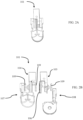
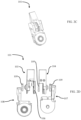
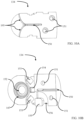
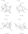
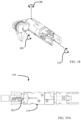
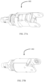
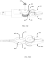
- FIG. 1A- 1F show multiple views of one embodiment of a wrist assembly 100.
- FIG. 1E and FIG. 1F show exploded views of one embodiment of the wrist assembly 100.
- the wrist assembly 100 consists of two subassemblies, a jaw assembly 101 and a hinge-rotary actuator assembly 102. Both of aforementioned subassemblies are essential to the overall wrist assembly 100, as both subassemblies in conjunction with one another are configured to provide a user with four degrees of freedom, as further detailed below.
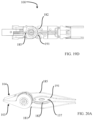
- FIG. 2A- 2D show multiple views of one embodiment of the jaw assembly 101.
- the jaw assembly 101 is an essential part to the overall wrist assembly 100, as it performs crucial functions.
- the jaw assembly 101 functions as an end-effector for the Virtual Reality Surgical Device and is configured to interact with the surgical environment and perform surgical procedures within the operation work space.
- the jaw assembly 101 is configured to provide a surgeon with two DOFs, as well as configured to mate and couple to the hinge-rotary actuator assembly 102 to provide a surgeon with two additional DOFs.
- the working segment 179 and the actuation hub 180 are manufactured as one solid piece, while in other embodiment the working segment 179 and the actuation hub 180 are affixed to each other via a welded connection, adhesive connection, and/or any other connection methods or techniques known in the art.
- the working segment 179 of the second jaw 104 allows a surgeon to grasp, and manipulate tissues, as well as grasp surgical tools.
- working segment 179 can take on a myriad of configurations, allowing a surgeon to perform a variety of procedures and tasks.
- working segment 179 of the second jaw 104 contains rigid teeth on one side of said segment so to provide a surgeon with a gripping surface to hold and manipulate tissue and organs.
- the working segment 179 is configured to contain a textured surface, smooth surface, a knurled surface, and/or have a protective coating on one side of said segment.
- working segment 179 is configured to be electrically conductive.
- the first jaw 103 and the second jaw 104 are configured as a cautery tool, allowing a surgeon to perform cautery functions.
- electrical cautery wires are routed through the wrist assembly 100 to the first and second jaw, with the first and second jaws containing electrical insulation, so as to electrically isolate the first and second jaws or the working segments 183 and 179 from the rest of the wrist assembly 100.
- the working segments 183 and 179 of the first and second jaw are configured to perform electrocautery functions, utilizing both the monopolar cautery method, as well as the bipolar cautery method.
- the second jaw 104 contains the actuation hub 180.
- the actuation hub 180 of the second jaw 104 contains a cable routing raceway 111.
- the cable routing raceway 111 is configured to allow a cable 181 (not shown in FIGS. 3A-3D ), to sit within said raceway, as well as to route the cable 181 to a cable aperture 115 located on the working segment 179 of the second jaw 104.
- the cable routing raceway 111 is configured to constrain the cable 181, so as to prevent said cable 181 from slipping off the raceway during actuation.
- the cable routing raceway 111 extends around the perimeter of the actuation hub 180, thus providing a surface for cable 181 to sit and ride along during actuation.
- FIGS. 4A- 4D show multiple views of an illustrative embodiment of the first jaw 103.
- the first jaw 103 is fabricated to have a distal end containing a working segment 183 and a proximal end containing an actuation hub 184.
- the working segment 183 and the actuation hub 184 of the first jaw are manufactured as one solid piece, while in other embodiments the working segment 183 and the actuation hub 184 are affixed to each other via a welded connection, an adhesive connection, and/or any other connection methods or techniques known in the art.
- the actuation hub 184 of the first jaw 103 is fabricated to be circular in shape and contains two sides. Similar to the actuation hub 180 of the second jaw 104, in one embodiment, one side of the actuation hub 184 of the first jaw 103 contains a bearing race 116b, which is configured to allow one of the pluralities of ball bearing sets 109 to ride on. As mentioned above, in some embodiments the ball bearing set 109 are eliminated as certain embodiments of the technology do not require ball bearings. Certain embodiments comprise sleeve bearings, bushings, axle and/or other rolling element bearings known in the art.
- actuation hub 184 contains a cable routing pin 118, which is configured to route cable 182 to its respective termination site 110.
- the cable routing pin 118 is coupled to a cable routing protrusion 119a.
- the cable routing protrusion 119a provides a surface for cable 182 to ride along when the first jaw 103 is actuated in a first direction.
- cable routing protrusion 119a is configured to allow cable 182 to wrap around said protrusion 119a, effectuating a reduced change in length of cable 182 when the first jaw 103 is actuated in a first direction about the jaw axis, as well as configured to reduce torque about the jaw axis during rotation.
- actuation hub 184 contains another cable routing protrusion 119b, which provides a surface for cable 182 to ride along during actuation of the first jaw 103 in a second direction. Similar to cable routing protrusion 119a, cable routing protrusion 119b is configured to allow cable 182 to wrap around said protrusion 119b, and also configured to effectuate a reduced change in length of cable 182 when the first jaw 103 is actuated in a second direction about the jaw axis, as well as reduce torque about the jaw axis during rotation.
- the actuation of the first jaw 103 and the second jaw 104 is further detailed below.
- connection pin 122a also provides a routing surface for cable 182 to guide said cable 182 to its termination site 110.
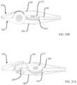
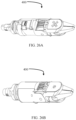
- FIGS. 22A-22B show an illustrative embodiment of an actuation hub with an alternative configuration.
- a first jaw 203 contains an actuation hub 284 and a working segment 283.
- the actuation hub 283 contains a plurality of pulley pockets 204.
- the pulley pocket 204 is configured to allow a cable pulley 202 ( FIGS. 23A-23B ) to sit within.
- protruding from the pulley pocket 204 is a fulcrum 201, which is configured to allow the cable pulley 202 to rotate about.
- the cable pulley 202 contains an aperture for which the fulcrum 201 passes through.
- the fulcrum(s) 201 are configured to mate and couple to connection apertures 221 located on a redirecting cable hub 206 ( FIG. 25A ).
- Redirecting cable hub 206 is configured to perform the same function as redirecting cable hub 106 detailed below.
- redirecting cable hub 206 contains a cable raceway 220 which extends around the perimeter of the redirecting cable hub 206.
- the redirecting cable raceway 220 provides a surface for cable 185 to ride along during actuation of the jaw assembly 101.
- redirecting cable raceway 220 is configured to retain cable 185 within said raceway 220 during actuation of the jaw assembly 101, such that cable 185 does not pop and/or slip off said raceway.
- redirecting cable hub 206 also contains a bearing race 223 on one side, which is configured to allow a ball bearing set to sit in, and house said set. Bearing race 223 provides a surface for the redirecting cable hub 206 to rotate.
- bearing race 223 is configured to allow rotational motion about the axis of the redirecting cable hub, while preventing axially movement in all other axes, similar to the bearing race 123 of redirecting cable hub 106 detailed below.
- the actuation hub 284 of the first jaw 203 also comprises a cable routing protrusion 218, which is configured to ensure that a cable being routed about the cable pulley 202 maintains contact with said pulley during actuation of the jaw assembly.
- the cable pulleys 202 are configured to reduce the friction imparted on the cable routed about it, so as to limit the amount of wear on the cable during actuation, as well as increase the force the first jaw 203 can apply.
- the cable pulley 202 reduces stick-slip which causes jerky motion thus improving the motion the first jaw 203 during actuation. As seen in FIG.
- first jaw 203 contains a cable routing aperture 215 and a cable termination site 205 on the working segment 283 of the first jaw 203.
- actuation hub 284 has two sides, with one side configured to contain the cable pulleys 202 as detailed above, and one side configured to contain a bearing race for which a ball bearing set sits and rides within, similar to actuation hub 184 detailed above.
- cable 182 wraps around cable pulleys 202.
- the cable wrap angles will vary depending on the placement of the cable pulleys 202 on the actuation hub 284, as well as the position of the first jaw 203 along its rotational axis.
- the wrap angle around cable pulley 202a will vary between about 240 to 300 degrees. In other embodiments, the wrap angle around cable pulley 202a will vary between about 180 to 360 degrees.
- the wrap angle around cable pulley 202a will vary between about 220 to 320 degrees. In another embodiment, the wrap angle around cable pulley 202a will vary between about 200 to 340 degrees. In another embodiment, the wrap angle around cable pulley 202a will vary between about 260 to 300 degrees. Meanwhile, in some embodiments, the wrap angle around cable pulley 202b will vary between 0 to 110 degrees. In other embodiments, the wrap angle around cable pulley 202b will vary between 0 to 180 degrees. In another embodiment, the wrap angle around cable pulley 202b will vary between 0 to 130 degrees. In a further embodiment, the wrap angle around cable pulley 202b will vary between 0 to 150 degrees. In still a further embodiment, the wrap angle around cable pulley 202b will vary between 0 to 150 degrees.
- FIGS. 5A- 5C show multiple views of an illustrative embodiment of the redirecting cable hub 106.
- the redirecting cable hub 106 is configured to route cables 182 and cable 185 to their respective termination sites 110 and 105b.
- the redirecting cable hub 106 is configured as a circular hub, which contains two sides and a redirecting cable raceway 120.
- the redirecting cable raceway 120 extends around the perimeter of the redirecting cable hub 106.
- the redirecting cable raceway 120 provides a surface for cable 185 to ride along during actuation of the jaw assembly 101.
- the redirecting cable raceway 120 is configured to retain cable 185 within said raceway 120 during actuation of the jaw assembly 101, such that cable 185 does not pop and/or slip off said raceway.
- connection pins 122a and 122b which are utilized to mate and couple the actuation hub 184 of the first jaw 103 with the redirecting cable hub 106.
- the actuation hub 184 of the first jaw 103 and the redirecting cable hub 106 are fabricated to be one piece.
- a cable routing pin aperture 121 located on one side of the redirecting cable hub 106 is a cable routing pin aperture 121.
- the cable routing pin aperture 121 is configured to allow the cable routing pin 118 located on the actuation hub 184 of the first jaw 103 to enter said aperture, thus coupling and mating actuation hub 184 and the redirecting cable hub 106.
- the coupling and mating of the cable routing pin 118 with the cable routing pin aperture 121 fashions a connection such that cable 182 maintains contact with the cable routing pin 118 during actuation of the jaw assembly 101 and prevent wedging and/or jamming of said cable.
- bearing race 123 located on one side of the redirecting cable hub 106, is a bearing race 123.
- bearing race 123 is configured to allow one of the pluralities of ball bearing sets 109 ( FIG. 2B ) to sit in, and house said set.
- Bearing race 123 provides a surface for the redirecting cable hub 106 to rotate.
- bearing race 123 is configured to allow rotational motion about the redirecting cable hub axis, while preventing axially movement in all other axes.
- Certain embodiments of the technology do not require ball bearings.
- Certain embodiments comprise bushings, sleeve bearings, axle and/or other rolling element bearings known in the art.
- the redirecting cable hub 106 is situated in between the actuation hub 184 of the first jaw 103 and the actuation hub 180 of the second jaw 104. As detailed above, one side of the redirecting cable hub 106 couples and mates with the actuation hub 184 of the first jaw 103, with the other side of the actuation hub 184 containing bearing race 123 ( FIG. 5B ).
- the bearing race 123 of the redirecting cable hub 106 is configured to have the same dimensions as the bearing race 113 located on the actuation hub 180 of the second jaw 104, so that when the actuation hub 180 of the second jaw 104 contacts the redirecting cable hub 106, said contact fashions a housing for one of the plurality of ball bearing sets 109 such that said ball bearing set sits and rides along both bearing race 113 and bearing race 123.
- bearing race 123 and bearing race 113 are not symmetric, or the same size, while in other embodiments bearing race 123 and bearing race 113 are substituted for axle.
- bearing races 116a and 116b are located on one side of the actuation hub 184 of the first jaw 103, as well as on one side of the actuation hub 180 of the second jaw 104. Both bearing races 116a and 116b are configured to allow one of the pluralities of ball bearing sets 109 to ride on. In some embodiments, bearing races 116a and 116b are both configured to mate with a hinge bearing race 127, with bearing race 116a mating with the hinge bearing race 127 located on the hinge non-flex body 108 ( FIG 7B ), and bearing race 116b mating with the hinge bearing race 127 located on the hinge flex body 107 ( FIG. 6B ).
- bearing race 116a and the hinge bearing race 127 of the hinge non-flex body 108 form a housing for one of the pluralities of ball bearing sets 109, with bearing race 116a functioning as an inner bearing race and the hinge bearing race 127 of the hinge non-flex body 108 functioning as an outer bearing race.
- bearing race 116b and the hinge bearing race 127 of the hinge flex body 107 form a housing for another one of the pluralities of ball bearing sets 109.
- the hinge flex body 107 and the hinge non-flex body 108 function as a housing for the first jaw 103, the second jaw 104, the redirecting cable hub 106, as well as some of the plurality of ball bearing sets 109.
- FIGS. 6A-6D show multiple views of an illustrative embodiment of the hinge flex body 107.
- FIGS. 7A-7D show multiple views of an illustrative embodiment of the hinge non-flex body 108.
- the hinge flex body 107 contains a proximal and distal end, with said ends comprising inner and outer surfaces.
- the hinge bearing race 127 situated on the inner surface of the distal end of the hinge flex body 107 is the hinge bearing race 127, which is configured to mate and couple with bearing race 116b of the first jaw 103 as detailed above.
- the mating between bearing race 116b of the first jaw 103 and the hinge bearing race 127 of the hinge flex body 107 also prevents the first jaw 103 from experiencing any transitional movement during actuation of said first jaw.
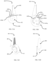
- the aforementioned mating also defines a jaw axis 189 ( FIG. 17A and FIG. 17C ) for which the first jaw 103 rotates about.
- the distal end of the hinge flex body 107 contains a magnet housing aperture 190 which is configured to allow the magnet housing 112b of the first jaw 103 to enter and mate with.
- a flex pocket 126 on the outer surface of the distal end of the hinge flex body 107 is a flex pocket 126.
- the flex pocket 126 is configured to allow an electrical communication component to sit within, so as to prevent any damage to said component during actuation of the jaw assembly 101.
- different electrical communication components are utilized, including but not limited to rigid flexible printed circuit boards (RFPCB), flexible printed circuit board (FPCB), and/or any other type of electrical communication component known in the art.
- Electrical communication components which sit in the flex pocket 126 of the hinge flex body 107 are utilized to transmit position and/or orientation data of the first jaw 103, to a central computer which processes said data and transmits control commands and/or prompts to actuators which actuate and manipulate the first jaw 103.
- the position and/or orientation data of the first jaw 103 is obtained from magnet(s) located in magnet housing 112b, as well as sensors situated in the flex pocket 126 of the hinge flex body 107.
- the flex pocket 126 of the hinge flex body 107 contains sensors for sensing the change in magnetic field of the magnet(s) in magnet housing 112b as the first jaw 103 is rotated about the jaw axis 189.
- two rotational position sensors are found in the flex pocket 126 of the hinge flex body 107 for sensing the change in magnetic field, while in other embodiments four rotational position sensors are found.
- the magnet sensing is further detailed below.
- the hinge flex body 107 contains a proximal end.
- the proximal end of the hinge flex body 107 is utilized to couple and mate the jaw assembly 101 with the hinge-rotary assembly 102, as well as defines a pitch axis 188 ( FIG. 17A and FIG. 17B ).
- the proximal end of the hinge flex body 107 is constructed to have two sides an interior and exterior side.
- the exterior side contains a flex slot 124 which is configured to route an electrical communication component to the flex pocket 126 located on the outer surface of the distal end of the hinge flex body 107.
- the exterior side of the proximal end of the hinge flex body 107 contains a hinge hard stop 186.
- the hinge hard stops 186 is configured to constrain the jaw assembly 101 from rotating about the pitch axis 188 ( FIG. 17A ) past an allowable limit of articulation.
- the allowable limit of articulation is 120 degrees, having 60 degrees of motion in either direction, while in other embodiments the allowable limit of articulation is increased and/or decreased.
- the hinge hard stops 186 are configured as extruded surfaces that make contact with the distal end of the hinge-rotary assembly 102 to prevent the jaw assembly 101 from being actuated past an allowable degree of rotation.
- the proximal end of the hinge flex body 107 is configured to be circular in shape, so as to allow the hinge-rotary assembly 102 to rotate about the pitch axis 188 during actuation.
- connection apertures 125 are configured to allow a male bearing race 138 (FIGS. 15A- 15D) from the hinge-rotary assembly 102 to mate and couple to.
- the connection apertures 125 are situated on a protruded surface above the flex slot 124, such that electrical communication components can be routed through said slot without any interference from the male bearing race 138.
- the connection apertures 125 are eliminated, with the male bearing race 138 fabricated to be a part of the proximal end of the hinge flex body 107.
- the fulcrum 128 is configured to be cylindrical in shape, having an outer diameter that allows the fulcrum 128 to pass through an aperture on an idler pulley 137 ( FIG. 16A ).
- the fulcrum 128 is substituted for a bearing or any axle known in the art.
- the proximal end of the hinge flex body 107 contains a jaw hard stop 187.
- the jaw hard stop 187 is configured to constrain the first jaw 103 and the second jaw 104 from rotating about the jaw axis 189 ( FIG. 17A and FIG. 17C ) past an allowable limit of articulation.
- the jaw hard stop 187 is configured as an extruded surface that makes contact with the proximal end of the first and second jaw to prevent said jaws from being actuated past an allowable degree of rotation.
- the allowable degree of rotation is 93 degrees in either direction, while in other embodiments the allowable degree of rotation is less than or more than 93 degrees of rotation in either direction.
- FIGS. 7A-7D show multiple views of an illustrative embodiment of a hinge non-flex body 108. As shown in FIGS. 7A-7D , in one embodiment, the hinge non-flex body 108 is fabricated to contain a proximal and distal end.
- the distal end of the hinge non-flex body 108 contains a magnet housing aperture 190 which is configured to allow the magnet housing 112a of the second jaw 104 to enter and mate with.
- the hinge non-flex body 108 contains a proximal end.
- the proximal end of the hinge non-flex body 108 is utilized in conjunction with the proximal end of the hinge flex body 107 to couple and mate the jaw assembly 101 ( FIG. 1D ) with the hinge-rotary assembly 102 ( FIG. 1D ), with said mating and coupling defining the pitch axis 188 ( FIG. 17A and FIG. 17B ).
- the proximal end of the hinge non-flex body 108 is constructed to have two sides, with one side containing a hinge bearing race 129.
- the jaw hard stop 187 is configured as an extruded surface that makes contact with the proximal end of the first and/or second jaw to prevent said jaws from being actuated past an allowable degree of rotation.
- the allowable degree of rotation is 93 degrees in either direction, while in other embodiments the allowable degree of rotation is less than or more than 93 degrees of rotation in either direction.
- the hinge-rotary assembly 102 is also configured to provide another DOF, with this DOF being the rotation of the wrist assembly 100 about a roll axis 192 ( FIG. 18 ). Furthermore, in addition to providing two extra DOFs, the hinge-rotary assembly 102 also functions as an intermediary, connecting the electrical communication components of the jaw assembly 101, with electrical communication components of the rest of the robotic arm, so as to allow the data obtained from sensors on the jaw assembly 101 to be transmitted from said assembly, through the hinge-rotary assembly 102 to a central computer, as well as to allow data to be transmitted from the central computer back to the jaw assembly 101.
- the hinge-rotary assembly 102 contains a female hinge body, also referred to as a hinge cover 134 and a male rotary-hinge body, also referred to as a hinge-rotary body 139.
- the female hinge body 134 along with the male rotary-hinge body 139 are fabricated to function as a housing for various components of the hinge-rotary assembly 102, as well as a connection and mating point for the proximal ends of the hinge flex body 107 and hinge non-flex body 108.
- FIG. 9A and FIG. 9B show multiple views of an illustrative embodiment of a male rotary-hinge body 139.
- the male rotary-hinge body 139 contains a distal and proximal end, as well as outer and inner surfaces.
- the proximal end of the male rotary-hinge body, also referred to as hinge-rotary body 139 contains a cable conduit 142.
- the cable conduit 142 is fabricated as a cylindrical shaft, having an aperture for which cables 181, 182, 185, and 191 (not shown in FIG. 9A ) are routed through.
- the cable conduit 142 is configured to allow the aforementioned cables to be routed through said conduit, such that when the wrist assembly 100 is rotated about the roll axis 192, the cables do not become tangled with one another.
- located on the outer surface of the cable conduit 142 is a bearing interface 193, on which a bearing (not shown) sits, said bearing is configured to allow for rotation of the cable conduit 142 through a variety of loading conditions.
- a flex guide surface 145 located on the inner surface of the cable conduit 142 is a flex guide surface 145.
- the flex guide surface 145 is configured to be a flat surface for which an electrical communication component(s) rests on.
- the flex guide surface 145 is also configured to route and guide electrical communication component(s) from a robotic arm through the proximal end of the hinge-rotary assembly 102, where said component(s) operatively connect to other electrical communication component(s) that are routed from the jaw assembly 101 through the distal end of the hinge-rotary assembly 102.
- the flex guide surface 145 is fabricated so electrical communication component(s) sits flat against said surface, such that during actuation of the wrist assembly 100 said component(s) are not bent and/or damaged.
- electrical communication is transmitted through the cable conduit 142 via standard electrical communication wires and/or cables known in the art, including but not limited to copper cables and/or fiber optic cables.
- the cable conduit 142 is configured to allow a rotary pulley body 140 to connect and mate with the male rotary-hinge body 139.
- the rotary pulley body 140 is fabricated to have an opening in its center to allow the cable conduit 142 to pass through.
- the rotary pulley body 140 connects and mates with the male rotary-hinge body 139 via a screw connection, with screws passing through through-holes 149, and entering tapped holes 168 ( FIG. 13B ), on the rotary pulley body 140.
- the rotary pulley body 140 is coupled to the male rotary-hinge body 139 via a pin connection, with pins entering and sitting with pin connection apertures 144 located on both the male rotary-hinge body 139 and the rotary pulley body 140.
- the pin connection is configured to constrain the rotary pulley body 140 to the male rotary-hinge body 139 such that the rotary pulley body 140 does not rotate during actuation of the wrist assembly 100 about the roll axis 192.
- the rotary pulley body 140 is fabricated as part of the male rotary-hinge body 139, thus eliminating the connections described above.
- the male rotary-hinge body 139 is configured to have a distal end having an inner and outer surface. As depicted in FIG. 9A , in some embodiments, located on the outer surface of the distal end of the male rotary-hinge body 139 is a cable guide slot 143. Cable guide slot 143 is configured to route and guide cable 181 from the hinge-rotary assembly 102 through the proximal end of the jaw assembly 101 to the cable routing raceway 111 ( FIG. 3A ) located on the actuation hub 180 of the second jaw 104.
- cable 181 is routed through the cable conduit 142 to the inner surface of the distal end of the male rotary-hinge body 139, where said cable passes through an aperture and enters the cable guide slot 143 on the outer surface of the distal end of the male rotary-hinge body 139.
- the cables are routed along decoupling surfaces 194.
- Decoupling surfaces may be configured to decouple cable motion from joint motion, to decouple joint motion from cable motion, or to decouple cable motion from joint motion and decouple joint motion from cable motion.
- the decoupling surfaces are fabricated to be curved in shape, such that when the first and second jaws rotate, the cables that close the jaws pivot about the center of the pitch axis 188 without changing length.
- the curve of the decoupling surfaces 194 allow the cables to wrap along it such that the cables neither lose tension or become over tensioned, as there is no sliding motion between the cable and the surface.
- the decoupling surfaces effectuate decoupled motion of the jaws when rotated about the jaw axis 189 and the jaw assembly when rotated about the pitch axis.
- a flex pocket 126 is also located on the outer surface of the distal end of the male rotary-hinge body 139.
- the flex pocket 126 is configured to allow an electrical communication component(s) to sit within and mount to said pocket, so as to prevent any damage to said component(s) during actuation of the wrist assembly 100.
- different electrical communication components are utilized, including but not limited to rigid flexible printed circuit boards (RFPCB), flexible printed circuit boards (FPCB), and/or any other type(s) of electrical communication components known in the art.
- the inner surface of the distal end of the male rotary-hinge body 139 contains a cable routing protrusion 146.
- the cable routing protrusion 146 is configured to direct cables routed through the distal end of the hinge-rotary assembly 102 to a desired location.
- the cable routing protrusion 146 is fabricated to be a smooth surface so that cables are not damaged during actuation.
- the cable routing protrusion is configured to function as a divider, so that the cables that are routed through the distal end of the male rotary-hinge body 139 do not become tangled or intertwined with each other, as well as to prevent said cables from catching or hooking on to another component of the wrist assembly 100 as said cables are routed to a desired location.
- the cable routing protrusion 146 is configured to have two sides, with one side routing one cable to a desired location, and the other side routing a different cable to a desired location. In one embodiment, the cable routing protrusion 146 is utilized to route cable 191 ( FIG. 19B ) and cable 182 ( FIG. 19B ), with cable 191 being routed on one side of the cable routing protrusion 146 and cable 182 being routed on the other side of the cable routing protrusion 146.
- cable 191 is routed through the distal end of the male rotary-hinge body 139 to cable raceway 130 located at the proximal end of the hinge non-flex body 108
- cable 182 is routed through the distal end of the male rotary-hinge body 139 to an idler cable raceway 178 located on the idler pulley 137 ( FIGS. 16A-16B ), as further detailed below.
- the cable routing protrusion 146 is eliminated and replace by channels and/or conduits that direct cables to a desired location.
- the inner surface of the distal end of the male rotary-hinge body 139 contains a plurality of tapped holes 148.
- the tapped holes 148 are configured to allow a screw to enter, thus mating and coupling the female hinge body 134 with the male rotary-hinge body 139, as detailed below.
- one or more of the plurality of tapped holes 148 are utilized to mate and couple a bottom flex cover 136 ( FIG. 8B and FIGS. 11A-11B ) to the male rotary-hinge body 139.
- the inner surface of the distal end of the male rotary-hinge body 139 comprises a bearing race 147 ( FIG. 9B ).
- the bearing race 147 is configured to allow one of the pluralities of ball bearing sets 109 to sit within, and ride along during articulation of the wrist assembly 100.
- the one of the pluralities of ball bearing sets 109 ( FIG. 8B ) that sits within the bearing race 147 of the male rotary-hinge body 139 also sits on a bearing raceway 175 ( FIG. 15A ) located on the male bearing race 138 ( FIG. 15A ).
- the male bearing race 138 is configured to couple to the bearing race 147 of the distal end of the male rotary-hinge body 139, as well as with the proximal end of the hinge flex body 107.
- the hinge-rotary assembly has a top flex cover 135 and a bottom flex cover 136 ( FIGS. 11A - 11B and FIGS. 12A - 12B ).
- the bottom flex cover is fabricated to have an inner and outer surface.
- the inner surface of the bottom flex cover 136 is a cable routing passage 160 which is utilized for cables from the proximal end of the hinge-rotary assembly to pass through.
- the outer surface of the bottom flex cover 136 has a flex pocket 157 for which electrical communication components from the jaw assembly, as well as from the hinge-rotary assembly sit.
- Flex pocket 157 is configured to allow the electrical communication components to sit flat in said pocket.
- the outer surface of bottom flex cover 136 has a through-hole 158 which is configured to let a screw to pass through and enter a tapped hole 148 ( FIG. 9B ) on the male rotary-hinge body 139.
- screw cut-outs 161 located on the proximal end of the bottom flex cover 136 are screw cut-outs 161, which are configured to allow the head of a screw to sit in. In these embodiments, the screws that sit within the screw cut-outs 161 are used to mate male-rotary-hinge body 139 and the rotary pulley body 140 ( FIGS. 13A - 13D ).
- connection aperture 159 which is configured to allow a connection nub 162 on the top flex cover 135 to enter and thus mate the top and bottom flex covers.
- the connection between the top flex cover 135 and bottom flex cover 136 is depicted in FIGS. 12A - 12B , according to some embodiments.
- the top flex cover 135 is configured to mate with the bottom flex cover 136 and thus protect the electrical communication components which are situated in the flex pocket 157 of the bottom flex cover 136.
- the top and bottom flex covers are fabricated as part of the female hinge body or hinge cover 134.
- FIGS. 15A-15B show multiple views of an illustrative embodiment of a male bearing race 138.
- the male bearing race 138 is fabricated to have two sides, with one side containing the bearing raceway 175, and the other side containing a plurality of male bearing connection nubs 176.
- the bearing raceway 175 is configured to allow one of the pluralities of ball bearing sets 109 to sit within and ride along said raceway, as well as sit within and ride along the bearing race 147 located on the male rotary-hinge body 139.
- the plurality of male bearing connection nubs 176 are configured to enter and mate with the connection apertures 125 ( FIG.
- FIGS. 10A-10B show multiple views of an illustrative embodiment of the female hinge body or hinge cover 134.
- the female hinge body 134 contains an inner and outer surface.
- the outer surface of the female hinge body 134 contains a plurality of connection apertures 151.
- the connection apertures 151 are configured to allow screws to enter and pass through said apertures, with said screws entering and mating with the tapped holes 148 located on the male rotary-hinge body 139, thus coupling the female hinge body 134 with the male rotary-hinge body 139.
- a cable routing slot 150 also located on the outer surface is a cable routing slot 150.
- the cable routing slot 150 extends from the inner surface of the female hinge body 134 to the outer surface of said body. Similar to the cable guide slot 143 of the male rotary-hinge body 139, the cable routing slot 150 of the female hinge body 134 is configured to route and guide cable 185 from the hinge-rotary assembly 102 through the proximal end of the jaw assembly 101 to the redirecting cable raceway 120 ( FIG. 5A ).
- cable 185 is routed through the cable conduit 142 of the male rotary-hinge body 139 to the inner surface the female hinge body 134, where said enters the cable routing slot 150 and passes through an aperture, such that the cable is situated in the cable routing slot on the outer surface of the female hinge body 134.
- decoupling surfaces 195 are harmonious to the decoupling surfaces 194 of the hinge-rotary body 139, in that they are fabricated to be curved in shape, such that the cable routed through said routing slot do not change in length when the jaw assembly is rotated about the pitch axis, thus helping to effectuate the decoupled motion.
- a flex pocket 156 and a flex routing protrusion 155 located on the inner surface of the female hinge body 134.
- the flex pocket 156 and the flex routing protrusion 155 are configured to harmoniously route electrical communication components to a plurality of sensor pockets 153 and an electrical communication pocket 154 located on the inner surface of the female hinge body 134.
- the flex pocket 156 is also configured to act as a housing for said communication components, such that said components are not damaged during actuation and articulation of the wrist assembly 100.
- a communication component pocket 154 and sensor pockets 153 located on the inner surface of the female hinge body 134 is a communication component pocket 154 and sensor pockets 153.
- the sensor pockets 153 are configured to allow position and/or orientation sensors to sit in said pockets, such that they do not become damaged during actuation of the wrist assembly 100.
- the sensor pockets 153 are situated on the inner surface of the female hinge body 134 such that said pockets are orthogonal to one another about the center point of a magnet pocket 152 located on the hinge non-flex body 108 ( FIG. 7B ).
- a variety of position sensors may be used, including but not limited to, hall-effect sensors, optical encoders, resistive position sensors, and/or any other standard means of measuring position or combination thereof.
- the sensors which sit in the sensor pockets 153 are configured to obtain position and/or orientation data of the jaw assembly 100 as said assembly is rotated about the pitch axis 188.
- the communication component pocket 154 is configured to house capacitors.
- capacitors are utilized to reduce signal noise from the sensors and other electrical communication components, so as to provide more accurate sensor readings, resulting in more accurate position data.
- the communication component pocket 154 is configured to house two or more capacitors, while in other embodiments only one capacitor is housed in said component pocket.
- the communication component pocket 154 is configured to house components required for measurement and/or communication, such as inductors, resistors and/or processors known in the art.
- the inner surface of the female hinge body 134 contains a bearing race 147.
- the bearing race 147 is configured to allow a ball bearing set 109 to sit within and ride along said race during actuation of the wrist assembly 100.
- the ball bearing set 109 which sits within the bearing race 147 of the female hinge body 134 also sits within the hinge bearing race 129 of the hinge non-flex body 108 ( FIG. 7A ), fashioning a coupling between the female hinge body 134 and the hinge non-flex body 108.
- the aforementioned coupling between the female hinge body 134 and the hinge non-flex body 108 allows the jaw assembly 101 to rotate about the pitch axis 188.
- both the hinge flex body 107 and hinge non-flex body 108 couple to the inner surfaces of the distal ends of both the male rotary-hinge body 139 and the female hinge body 134, thus coupling the jaw assembly 101 with the hinge-rotary assembly 102.
- the aforementioned coupling of the distal end of the male rotary-hinge body 139 to the proximal end of the hinge flex body 107 and the distal end of the female hinge body 134 to the proximal end of the hinge non-flex body 108 also constrains the jaw assembly 101 such that during actuation, the jaw assembly can only be rotated about the pitch axis 188.
- the proximal ends of the hinge flex body 107 contains a fulcrum 128 for which the idler pulley 137 rotates about.
- FIGS. 16A-16B show multiple views of an illustrative embodiment of the idler pulley 137.
- the idler pulley 137 in combination with the proximal ends of both the hinge flex body 107 and the hinge non-flex body 108 and the distal ends of both the male rotary-hinge body 139 and the female hinge body 134 is configured to provide rotational movement of the jaw assembly 101 about the pitch axis 188.
- the idler pulley 137 is configured to route cable 182 to the actuation hub 184 of the first jaw 103.
- the idler pulley 137 contains an idler cable raceway 178.
- the idler cable raceway 178 is configured to route cable 182 to the actuation hub 184 of the first jaw 103.
- the idler pulley 137 contains an opening for which the fulcrum 128 of the hinge flex body 107 passes through.
- the interior surface of the opening of the idler pulley 137 contains a bearing race 177.
- the bearing race 177 of the idler pulley 137 is configured to allow one of the pluralities of ball bearing sets 109 to sit within and ride along said race.
- the hinge rotary assembly 102 also comprises a rotary pulley body 140.
- the rotary pulley body 140 mates and couples to the male rotary-hinge body 139.
- FIGS 13A-13D show multiple views of an illustrative embodiment of a rotary pulley body 140.
- the rotary pulley body 140 is configured to be cylindrical in shape having an opening so as to allow the proximal end of the male rotary-hinge body 139 to pass through said opening.
- the rotary pulley body 140 contains a distal and proximal end, with the distal end containing a plurality of tapped holes 168 configured to allow screws from the proximal end of the male rotary-hinge body 139 to enter said holes, coupling the rotary pulley body 140 to the male rotary-hinge body 139 ( FIG. 9B ). Additionally, as detailed above, in some embodiments the distal end of rotary pulley body 140 contains a plurality of pin connection apertures 144 ( FIG. 13B ).
- the distal end of the female rotary body 141 contains a plurality of sensor pockets 169, with said pockets protruding to the inner surface of the female rotary body 141 ( FIG. 14C ).
- the plurality of sensor pockets 169 are configured to house sensors for determining position and/or orientation of the wrist assembly 100 about the roll axis 192, similar to the sensor pockets 153 of the female hinge body 134 detailed above.
- the position and/or orientation of the wrist assembly 100 are measured using magnets in the same manner detailed above for determining the position and/or orientation of the jaw assembly 101 about the pitch axis 188.
- FIG. 30A shows an illustrative embodiment of the jaw assembly 401.
- jaw assembly 401 comprises a first jaw 403, a second jaw 404, two bodies a hinge flex body 407 and a hinge non-flex body 408, four idler pulleys 437, a jaw bearing shaft 410 and a hinge pulley shaft 409, amongst other components.
- FIGS. 31A - 31D show an illustrative embodiment of the first jaw 403.
- the first jaw 403 and the second jaw 404 are symmetrical.
- the first jaw and the second jaw both comprise a working segment 483 at the distal end of the jaw, as well as an actuation segment (or hub) 484 at the proximal end of the jaw.
- the working segments of the first jaw and second jaw are analogous to the working segments of other embodiments of the first jaw, in that it can be configured to have various types of surfaces in different embodiments, including but not limited to the configurations detailed above.
- the distal end of the first and second jaws are configured to have an actuation segment 484.
- cables 482 and 491 are routed and terminated on the first jaw, with cables 485 and 481 being routed and terminated on the second jaw. In other embodiments, cable 482 and 491 are routed and terminated on the second jaw and cables 485 and 491 are routed and terminated on the first jaw.
- the respective cables are routed through the raceway of their respective actuation segment where they enter and pass through a first cable passage 420a, then back through a second cable passage 420b, where said cable is routed to its termination site.
- the actuation segment of the first and second jaw are fabricated to have four cable passages 420a, 420b, 420c, 420d, two for each of the two cables that terminate on the actuation segment.
- the cables terminate by means of clamping the respective cable in its termination site via a setscrew.
- other appropriate means or techniques known in the art are used.
- a polymer fiber cable may terminate via a knot tied in the cable, while a metal fiber cable may terminate by means of a crimp or swaged connection.
- the actuation segment of the first and second jaw both comprise a magnet slot 452 configured to allow a magnet 421 to sit in.
- the magnets are utilized to obtain position and orientation data of components of the wrist assembly as said assembly is actuated about an axis.
- the magnets 421 which sit within the magnet slots 452 of the first and second jaws are utilized to obtain the position and orientation of the first and second jaws, as said jaws are rotated about the jaw axis.
- the magnet slots are configured to have a through hole, so as to allow the jaw shaft to pass through.
- the magnets 421 which sit within the magnet slots are also fabricated to have a through hole to allow the jaw shaft to pass through, with one end of the jaw shaft mating with the hinge flex body and the other end mating with the hinge non-flex body.
- a second locking pin connection is found on the hinge non-flex body, the two locking pin connections 406 not only mate the hinge flex body with the hinge non-flex body, but also constrains the rotation of the jaw assembly about the pitch axis.
- the proximal end of the hinge flex body is configured to have a jaw hard stop surface 487, in order to constrain the rotation of the jaw assembly about the pitch axis, such that the jaw assembly is not rotated past its allowable range of motion.
- the hinge flex body is fabricated to have a distal end having an interior and exterior surface.
- the interior surface of the distal end of the hinge flex body is fabricated to have an actuation segment pocket 422 that is cylindrical in shape, such that the actuation segment of the first jaw sits within said pocket.
- the actuation pocket 422 is fabricated to have a cable routing surface 423 to help guide cables to the cable raceway of the actuation segment, as well to have a through hole for the jaw bearing shaft to pass through thus effectuating a plain bearing.
- a second flex pocket for additional electrical communication components to sit in, as well as sensors for obtaining the position and orientation of the first jaw. In some embodiments two sensors are found in the flex pocket, while in other embodiments four sensors are found in the flex pocket.
- FIGS. 33A - 33B show an illustrative embodiment of the hinge non-flex body 408.
- the hinge non-flex body is fabricated to have proximal and distal end, with both ends having an interior and exterior surface.
- the interior surface of the distal end of the hinge non-flex body is fabricated to have an actuation segment pocket 422 that is cylindrical in shape, such that the actuation segment of the second jaw sits within said pocket.
- the actuation pocket is fabricated to have a cable routing surface 423 to guide cables to the cable raceway of the actuation segment.
- the actuation pocket 422 is fabricated to have a through hole for the jaw bearing shaft to pass through thus effectuating a plain bearing.
- a flex pocket 426 for electrical communication components to sit in, as well as sensors for obtaining the position and orientation of the second jaw.
- two sensors are found in the flex pocket, while in other embodiments four sensors are found in the flex pocket 426.
- the proximal end of the hinge non-flex body contains a jaw axis hard stop 487 to prevent the jaws from being actuated about the jaw axis past their allowable range of motion.
- the proximal end contains a locking pin connection 406 identical to the one detailed above for the hinge flex body.
- the exterior surface of the proximal end of the hinge non-flex body contains a pitch hard stop 488, which is configured to prevent the jaw assembly 401 from being actuated about the pitch axis past its allowable range of motion.
- FIGS. 27A - 27B show an illustrative embodiment of the hinge-rotary assembly 402.
- hinge-rotary assembly 402 is fabricated to have a hinge cover 434, a hinge-rotary body 439 and a rotary pulley body 440.
- the hinge-rotary body 439 performs the same function as the male hinge-rotary body 139 detailed above.
- FIGS. 28A - 28B shows an illustrative embodiment of the hinge-rotary body 439. Similar to the male hinge-rotary body detailed above, in these embodiments the hinge-rotary body 439 has a distal and proximal end, as well as interior and exterior surfaces. As seen in FIG.
- the magnet 490 that sits with the magnet pocket 453 of the hinge-rotary body is utilized to obtain position and orientation data of the jaw assembly as it is rotated about the pitch axis.
- the magnet pocket is configured to have a through hole for the hinge pulley shaft to sit in, thus creating a plain bearing.
- through holes 449 located on the interior of the distal end of the hinge-rotary body are through holes 449 which are configured to all a screw to enter and thus mate and couple the hinge cover 434 to the hinge-rotary body 439.
- the interior of the distal end is fabricated to have curved surfaces for guiding cables to the respective locations on the jaw assembly.
- located on the exterior surface of the distal end of the hinge-rotary body is a flex pocket 426 for which an electrical communication component sits.
- the proximal end of the hinge-rotary body is configured to have a cable conduit 442 similar to the one detailed above for the male hinge-rotary body.
- the cable conduit 442 is utilized to route cables to the jaw assembly, such that when the wrist assembly is rotated about the roll axis the cables do not become tangled with one another.
- a flex guide surface 445 located on the inner surface of the cable conduit 442 is a flex guide surface 445.
- the flex guide surface 445 is configured to be flat such that electrical communication components sit flat against the surface so as to not become damaged during actuation of the wrist assembly.
- an electrical communication component is routed on the flex guide surface to the flex pocket situated on the exterior of the distal end of hinge-rotary body.
- the electrical communication component is then routed to the interior surface of the hinge-rotary body, where it routed to the hinge cover 434.
- FIGS. 29A - 29C show an illustrative embodiment of the hinge cover 434.
- the hinge cover is analogous to the female hinge body 134 detailed above, in that acts as a housing for components of the hinge-rotary assembly, as well as used to route electronic communication components from the hinge-rotary assembly to the jaw assembly. As shown in FIGS.
- a routing protrusion 455 which creates a pocket for an electrical communication component to be routed to the jaw assembly.
- the interior surface of the hinge cover 434 contain connection apertures 444 for which screws from the hinge-rotary body enter, thus coupling the hinge cover with the hinge-rotary body.
- a through hole for which the hinge pulley shaft sits in.
- the hinge-rotary assembly 402 also contains a rotary pulley body 440.
- the rotary pulley body 440 is identical to rotary pulley body 140 detailed above.
- rotary pulley body 440 is utilized to provide rotation of the wrist assembly about the roll axis.
- the wrist assembly is fabricated and designed to be incorporated and utilized with the Virtual Reality Surgical Device disclosed in International Patent Application No. PCT/US2015/029247 (published as International Publication No. WO2015171614A1 ).
- the wrist assembly is actuated based on the movements of a user (typically a surgeon) who is controlling the robotic device disclosed in International Patent Application No. PCT/US2015/029247 .
- the surgeon's or user's arms movements are tracked via a sensor tracking system.
- a plurality of sensors are attached to the surgeon's arms.
- the senor utilized is an MPU-6050 sensor, which includes a MEMS gyroscope, accelerometer, and digital motion processor to compute the orientation of the sensor.
- a sensor is affixed to the right and left index finger, or other fingers, hand dorsum and forearm of the user.
- additional sensors are affixed to the user/surgeon's arms at different locations, including the upper arm, on the elbow of the user, while in other embodiments sensors are placed on the body of the user, including but not limited to the user's chest, torso or head.
- the sensor enclosures contain a microcontroller, battery, and Bluetooth module.
- Position and orientation data from the distal sensors on the user's arms are collected using 12C protocol along wires and transmitted to a computer. With data from the sensors affixed to the user's arms, the computer is able to compute the position and orientation of each portion of the user's arm.
- the addition of a magnetometer is standard practice in the field, as the magnetic heading allows for the reduction in sensor drift about the vertical axis.
- sensors are placed in surgical material such as gloves worn by the surgeon, surgical scrubs, or a surgical gown. These sensors may be reusable or disposable.
- additional sensors are used to track the position of the surgeon's arms and body.
- sensors similar to the sensors in the Xbox Kinect ® allow tracking of the absolute position of the user's arms and tracking of the arms positions relative to each other.
- these additional sensors are worn on the surgeons' body, while in other embodiments, sensors are positioned at fixed locations in the room.
- sensors are found in hand controllers held by the user.
- the sensors are used to control the robotic device with the movement of the user's hands.
- a sensor tracking system is used to monitor, record and transmit data from the sensors to a computer containing a control loop, with said control loop driving the actuators controlling the robotic device, including the wrist assembly.
- magnetic tracking us used in order to obtain position and orientation data of the user.
- known magnetic tracking and sensor systems from companies such as Polhemus ® and/or Northern Digital Inc. ® are utilized, while in other embodiments, other known magnetic tracking and sensors on the market and known in the field are used. Additionally, in some embodiments, the aforementioned magnetic tracking and sensor systems are utilized to track the user's arms and body.
- a magnetic transmitter or source is located within the operating theater, acting as a ground reference, which sends out an electromagnetic dipole field.
- the magnetic transmitter is connected to electronic control unit that generates the magnetic field and computes position and orientation data from sensors.
- the user wears a sensor, which can be located on any part of the user's body such as the chest, or head.
- the sensor worn by the user receives the electronic magnetic field from the transmitter and sends an electric current to the electronic control unit, providing data regarding the position and orientation of the sensor in relation to the transmitter.
- the raw position and orientation data obtained from the electronic control unit is then transmitted to a central computer connected to the unit, where the data is processed through software that computes the position and orientation of user's body.
- the sensor(s) located on the hand controllers are also operatively coupled to the electronic control unit, with said sensor(s) receiving the electromagnetic field from the transmitter and sending an electrical current from the sensor to the electronic control unit, providing data regarding the position and orientation of the controller in relation to the transmitter.
- the data from the sensors on the controller go through the same process described above for the sensor worn by the user.
- the central computer is able to infer the position and orientation of the controller in relation to the user's body, thus providing the position and orientation of the user's hand.
- the position and orientation data inferred by the computer is routed to a control loop which drives the actuators of the robotic arms, such that as the user moves his or her arm, the robotic arm follows and mimics the movement, allowing the user to control and manipulate the robotic arm(s).
- the user's arms and body and/or controller is tracked utilizing an optical tracking system.
- multiple cameras are strategically placed in the operating room/theater at various locations, while in other embodiments a single camera is used.
- Each of the cameras contains an infrared (IR) pass filter in front of the lens, and a plurality of IR LEDs around the lens to regularly illuminate the measurement space with IR light.
- IR infrared
- Located on the controller and/or the user's arms and body are retro-reflective markers which reflect the incoming IR light back to the cameras. The cameras detect the IR reflections from the markers and are internally processed by the optical tracking system.
- outside-in tracking is used to determine position and orientation of the user and the controller.
- the optical tracking system determines the two-dimensional positions of the markers in image coordinates, and with the utilization of multiple cameras, the three-dimensional position of each marker can be derived.
- the three-dimensional position can be measured using a single marker in the measurement space.
- the orientation of the controller and/or the user's arm and body can be measure by utilizing multiple cameras, as well as allowing for multiple objects to be tracked simultaneously.
- multiple cameras are placed around the operating theater, with multiple markers placed on each object to be tracked, such as the controller, the user's arm and body, amongst other items.
- inside-out tracking is used, with retro-reflective markers or light houses are placed at stationary locations around the operating room/theater, and/or on other objects, including equipment found in the operating room.
- cameras are affixed to the user body and arms and/or hand controller, with said cameras sending out IR light and the retro-reflective markers reflecting the light back on the camera(s) located on the user's arms and body and/or hand controller, thus providing position and orientation coordinates that can be used to derive the position and orientation of the user's arm.
- acoustic tracking and optical tracking without markers.
- a combination of the above-detailed tracking systems and methods are used in order to obtain position and orientation of a hand controller, as well as the body and arms of the user.
- sensor fusion is utilized, with various data being obtained from a variety of sensors and tracking system, with said data being processed through software on a computer to correct any deficiencies of any of the individual sensors in order to calculate accurate position and orientation information.
- the wrist assembly is fabricated to follow the movements and motions of the wrist of the user driving a robotic device to which the wrist assembly is coupled.
- different control methods, and systems are used, to actuate the wrist assembly. This is due different embodiments of the wrist assembly having different components and cables being routed differently.
- a control loop within the computer drives the actuators controlling the robotic device, which includes the wrist assembly.
- the wrist translations of the user are scaled down such that the wrist assembly follows the position of the human wrist and/or the controller held by the user.
- the wrist translations are scaled down due to difference in size between the wrist of the user and the wrist assembly.
- the wrist assembly is configured to follow the orientation of the user's wrist during actuation, such that, for example if the user rotates their wrist 90 degrees, the wrist assembly will rotate 90 degrees about the appropriate axis.
- the control scheme for the wrist assembly is further detailed below.
- the wrist assembly is configured to provide a surgeon with an assembly that has four (4) degrees of freedom (DOF), which allows a surgeon to emulate the wrist motion of the human arm. Additionally, as detailed above, in some embodiments, the wrist assembly is cable driven. In some embodiments, four cables are utilized to obtain three (3) of the DOFs, with two additional cables being utilized to obtain the fourth DOF. In alternative embodiments, three cables are utilized to control two of the DOFs, with the remaining two DOFs controlled by two cables each.
- DOF degrees of freedom
- the three DOFs are obtained by adjusting the length of the four cables, by pulling in on a specific cable, decreasing the length of that cable or letting out on a specific cable, increasing the length of that cable.
- the pulling in or letting out on a specific cable either compensates, counteracts and/or counterbalances the amount pulled in or let out on one or more of the other cables, depending on the desired motion.
- different control methods are used in different embodiments.
- the rotation and/or actuation of the wrist assembly 100 is achieved by the pulling in and letting out on each of the cables 181, 182, 185, and 191.
- the wrist assembly 100 is configured to provide two DOFs in the form of two independently moving jaws, one DOF in the form of a jaw assembly that pitches about an axis and an additional DOF in the form of an assembly that rolls about an axis.
- the wrist assembly 100 furnishes jaws that can apply a gripping force that can be increased and/or decreased to desired amount, thus allowing a surgeon to perform delicate tasks, as well as more robust tasks.
- said jaws can be simultaneously actuated in the same direction, with said actuation effectuating a yaw rotation of the jaws.
- FIGS. 19A- 19D shows multiple views of an illustrative embodiment of a wrist assembly 100, highlighting the routing of cables 181, 182, 185 and 191, through the wrist assembly 100.
- FIG. 19A shows a top profile view of an illustrative wrist assembly 100, highlighting the routing of cable 181 through the cable routing slot of the female hinge body or hinge cover 134.
- FIG. 19B shows a cut-away view of the wrist assembly 100 with the female hinge body removed, so as to highlight the routing of cable 182 and cable 191.
- cables 182 and 191 are routed through the inner surface of the male rotary-hinge body or hinge-rotary body 139.
- FIG. 19A shows a top profile view of an illustrative wrist assembly 100, highlighting the routing of cable 181 through the cable routing slot of the female hinge body or hinge cover 134.
- FIG. 19B shows a cut-away view of the wrist assembly 100 with the female hinge body removed, so as to highlight the routing of cable 182 and cable 191.
- FIG. 19C shows an additional top profile view of the wrist assembly 100, highlighting the routing of cable 185 through the cable routing slot of the male rotary-hinge body or hinge-rotary body 139.
- FIG. 19D shows a cut-away view of the wrist assembly 100 with the male rotary-hinge body removed, so as to highlight the routing of cables 182 and 191.
- the second jaw 104 is configured to rotate about the jaw axis 189 ( FIG. 18 ), in a first and second direction, with said rotation being independent from the first jaw 103.
- the second jaw 104 is configured to move between a first and second position, with said positions, including but not limited to an open and closed position.
- the second jaw 104 is actuated in a first direction, said direction including but not limited to rotation of the second jaw 104 towards the first jaw 103.
- FIG. 21B is an illustrative cabling diagram, highlighting how cables are routed to the second jaw 104 according to one embodiment. As detailed above, and depicted in FIG.
- cable 181 is routed through the hinge-rotary assembly and through the jaw assembly to cable termination site 105a located on the second jaw 104, where cable 181 terminates.
- cable 181 is pulled in via an actuator causing the second jaw 104 to start to rotate about the jaw axis 189 in a first direction.
- slack of cable 182 is let out, thus increasing the operative length of cable 182.
- the operative length of the cable is the distance between the connection pin 122a and the second jaw 104 as defined by the path of cable 182.
- the increase and/or decrease in the operative length of cable 182 results in movement of a jaw in either a first or second direction relative to the other jaw.
- the ball bearing set 109 which sits on bearing race 116a of the actuation hub 180 of the second jaw 104, and also sits on bearing race 127 of the hinge flex body 107, allows the second jaw 104 to rotate about the jaw axis 189. Since cable 181 terminates at termination site 105a located on the second jaw 104, the pulling in on cable 181 by the actuator is transferred on to the second jaw 104 resulting in said jaw rotating about the jaw axis 189 in a first direction.
- the length of cable 185 and cable 191 is held constant so as to prevent the first jaw 103 from moving.
- the length of cables 185 and 191 is either lengthened or shortened thus allowing the first jaw 103 to rotate in a first or second direction, while the second jaw 104 also rotates.
- the second jaw 104 is configured to be actuated in a second direction as well, with said second direction being opposite the first direction.
- cable 182 is pulled in, resulting in the operative length of cable 182 decreasing.
- cable 182 is routed around connection pin 122a and terminates on the second jaw 104.
- the operative length of said cable decreases, and thus the second jaw 104 rotates in the second direction relative to connection pin 122a and thus relative to the first jaw 103.
- the length of cable 191 is held constant to prevent any unwanted movement about the pitch axis 188.
- the length of cable 185 is held constant, to constrain the first jaw 103 in a fixed position, allowing the second jaw 104 to move in the second direction independently of the first jaw 103.
- the first jaw 103 is also configured to move independently in a first and second direction about the jaw axis 189.
- cable 185 is pulled in on via an actuator, causing the first jaw 103 to start to rotate.
- slack from cable 182 is released, thus increasing the operative length of cable 182.
- cable 182 passes through the wrist assembly 100 it is routed over the decoupling surfaces 195 and 194 detailed above, which are configured to enable adequate decoupling of the motion of cable 182 from other joints and/or cables.
- this decoupling of motion prevents cable 182 from imparting a force on the rest of the wrist assembly 100.
- the surfaces that cable 182 is routed about and/or through are configured to reduce the change in length of said cable, but cannot fully eliminate the length change. Any unwanted length change is corrected via sensors and control algorithms.
- the ball bearing set 109 which is sits on bearing race 116b of the actuation hub 184 of the first jaw 103, as well as on hinge bearing race 127 of the hinge non-flex body 108, allows the first jaw 103 to rotate about the jaw axis 189. Since cable 185 terminates at termination site 105b located on the first jaw 103, the pulling in on cable 185 by the actuator results in said jaw rotating about the jaw axis 189 in a first direction. To independently move the first jaw 103 cables 191 and 181 are held constant.
- the first jaw 103 is also configured to rotate about the jaw axis 189 in a second direction independently of the second jaw 104, with said second direction being opposite the first direction.
- cable 182 is pulled in by the actuator it is coupled to.
- the operative length of cable 182 decreases resulting in the first jaw 103 rotating in a second direction relative to the second jaw 104.
- cable 181 is held constant in order prevent elongation of said cable. Inhibiting the elongation of cable 181 prevents the second jaw 104 from rotating about the jaw axis 189 in a second direction.
- said configuration allows the jaws to be simultaneously actuated so that the jaws rotate about the jaw axis 189 together in either a first and/or second direction.
- This actuation effectuates a yaw movement of the jaws.
- cable 182 is held constant so there is no change in length. With cable 182 at a constant length, cable 181 is pulled on and slack from cable 185 is let out the same amount, with the change in lengths of the cables counteracting each other and thus rotating the jaws in a first direction.
- said configuration also allows a surgeon to apply a force with the jaws, with said force being variable, thus allowing a surgeon to control the amount of force applied by the jaws.
- a surgeon is able to complete a myriad of tasks, such as tissue manipulation, as well as grasping a surgical instrument or tool.
- the amount of force being applied by the jaws is determined by the amount length pulled in or let out on cables 181 and 185. In order to apply a force with the jaws, slack of cable 182 is released, with cable 182 wrapping around pin connection 122a.
- a o cable 181 is pulled in causing the second jaw 104 to move towards the first jaw 103, while simultaneously pulling in on cable 185 causing the first jaw to move towards the second jaw 104.
- additional force can be applied via the jaws by pulling in more on cables 181 and/or 185.
- slack is let out on cables 181 and/or 185.
- the wrist assembly 100 is also configured to allow the jaw assembly 101 to rotate about the pitch axis 188 in a first and second direction.
- a combination of cables are pulled in and/or let it out, with the amounts being pulled in and/or let out on each cable varying, so as to counteract the amount being pulled in or let out on a different cable.
- the length of cable 185 and cable 181 are held constant. Holding the length of the aforementioned cables constant, keep the jaws in a constant position, with sensors being used to counteract any undesired movement of said jaws.
- cable 191 is pulled in, thus shortening the length of cable 191.
- cable 191 is routed through the hinge-rotary assembly 102 and terminates at cable termination site 131 located on the proximal end of the hinge non-flex body 108.
- the decrease in the length of cable 191 imparts a force on the hinge non-flex body 108, at cable termination site 131, with said force causing the jaw assembly 101 to rotate about the pitch axis 188 in the first direction.
- the length of cable 182 lengthens and wraps around the idler pulley 137.
- cable 191 and 182 act together so as to allow the jaw assembly 101 to be rotated about the pitch axis 188 in a first direction, at the election of the surgeon.
- the rotation of the jaw assembly 101 about the pitch axis 188 in a second direction, with said second direction being opposite the first direction is accomplished by pulling in and/or letting out on a combination of cables, with said pulling in and/or letting out on cables counteracting the pulling in and/or letting out on other cables.
- slack of cable 191 is released thus increasing the length of cable 191.
- cable 182 is pulled in thus decreasing the length of cable 182.
- cables 181, 182, and 185 pass through the hinge-rotary assembly, and an additional cable is terminated on the hinge flex body.
- the additional cable works in conjunction with cable 191 to control rotation of the jaw assembly about the pitch axis in a first and second pitch direction.
- a combination of cables 181, 182, and 185 are used in opposition to cable 191 to control the rotation of the jaw assembly about the pitch axis in a first and second pitch direction.
- the remaining cables which are not used in opposition of cable 191 are non-opposing cables which pass through the hinge-rotary assembly without imparting additional torques about the joint.
- the first pitch direction is rotation about the pitch axis in one direction
- the second pitch direction being rotation about the pitch axis in the opposite direction of the first direction.
- the wrist assembly comprises magnets that are used to obtain position and orientation data of said assembly as it rotates about an axis.
- the magnets are diametrically magnetized, such that as the magnet rotates about its cylindrical axis its magnetic field changes.
- the change in the magnetic field is measured by the sensors, with said sensors transmitting the data to processors which convert the change in magnetic field to rotational position data. This conversion is done with knowledge of the physical configuration of the magnets(s), and sensor(s).
- several sensors are placed around the diametrically magnetized magnet orthogonally to each other. As the diametrically magnetized magnet rotates the magnetic field it generates also changes relative to the sensors.
- the change in magnetic field is transmitted to a computer via electrical communication components, such as PCBs or FPCBS.
- the computer takes the data obtained from the magnet regarding the change in the magnetic field and converts it into a degree of rotation.
- a combination of two orthogonally placed sensors can determine the direction of the magnetic field by comparing the relative field strength between the sensors. This calculation yields the orientation of the diametrically magnetized magnet, and by extension, the orientation of the wrist assembly as it is actuated about an axis. Additional sensors are placed in this embodiment for redundancy, but the total number of sensors necessary for the absolute orientation calculation will depend on the chosen configuration of the magnet and sensors.
- the magnet configured as a cylindrical magnet, while in other embodiments, a horseshoe magnet, disc magnet, sphere magnet, and/or other magnets shapes known in the art.
- a variety of sensors known in the art that are capable of magnetic field sensing can be used, including but not limited to hall effect sensors, and/or magnetoresistors.
- the sensors detailed above are continuously transmitting position and orientation data to a central computer, that processes the data and sends command prompts to the actuators of the wrist assembly in order to adjust the force being applied to or the position of the cables so as to correct for any undesired movement of the wrist assembly.
- sensors are used to determine the orientation of the wrist assembly during actuation about the pitch axis, jaw axis and roll axis.
- the first jaw and second jaw each have an independent sensor that reads the angular rotation of the individual jaw about the jaw axis.
- the sensor(s) for the first jaw are located on the hinge non-flex body, with the sensor(s) for the second jaw located on the hinge flex body.
- the sensors detailed above for the first and second jaw are used in conjunction with each other to determine the average angle of the first and second jaw about the jaw axis referred to herein as the angle of the wrist joint, as well as the angle between the first jaw and second jaw about the jaw axis, referred herein as the angle of the jaw joint.
- each independent joint of the wrist assembly is calibrated to zero out the individual angles and ensure one-to-one mapping between physical motion and sensed motion.
- each independent joint is moved through its range, and an external sensor that is already calibrated is used to record actual joint angles as the sensors collect their own sensed angles simultaneously.
- Standard calibration procedures known in the art may be used to calibrate the sensors to best match the sensed angles by the external sensors. Examples of calibrations include setting constant offsets, constant scaling factors, and variable offsets or scaling factors to a given sensor that are based on the positions of other sensors.
- a multiturn algorithm may be used to keep track of the absolute position of the joint, similar to how an incremental encoder can track an arbitrarily large range with only a few possible sensor readings. Any multi-turn or similar algorithm known in the art may be used for this purpose. An example of one possible algorithm is described here: at each time-step of the algorithm, the sensed joint angle is compared to the previously measured joint angle.
- the previously measured joint angle is set to the sensed joint angle.
- this large jump in angle is actually a result of the sensed angle passing through a discontinuity in the sensor (for example there may be a discontinuity between sensing -180 degrees and 180 degrees).
- the sensed joint angle may change from -175 degrees to +178 degrees in a given time-step.
- the algorithm appropriately adds or subtracts the full range of the sensor from the sensed joint angle until the difference between the sensed angle and previous angle is less than half of the sensor range.
- the previously sensed joint angle is then updated with the newly-computed sensed joint angle for the next iteration of the algorithm.
- a low-pass filter may be used to filter the previously sensed joint angle so that sensor noise or other fast changes in sensed angle are not mistaken for passing through a sensor discontinuity.
- the wrist assembly is ready to be actuated.
- the cables which actuate the jaws and the wrist assembly are operably coupled to actuators which drive the cables and thus actuate the wrist assembly.
- actuators including but not limited to servomotors, rotary actuators, linear actuators and/or stepper motors.
- electrical communication components are utilized to transmit position and orientation data to a computer which processes said data and transmits control commands and/or prompts to the actuators which apply position changes to the cables in order to actuate the jaws and wrist assembly in a desired manner.
- the actuators are controlled in position-control mode to pull the cables by various amounts in order to control the jaw joint, the wrist joint and the rotation of the wrist assembly about the pitch axis, which herein is referred to as the pitch joint.
- the actuators are controlled using actuator torque, winding current, voltage and/or angular velocity. Other actuation methods known in the art may alternatively be used.
- some combination of control modalities may also be used for the various actuators. For example, an agonist actuator may pull on a cable using force control, while the antagonist actuator for the same joint may drive its cable with position control.
- total motion of the cables of the wrist assembly is a superposition of the respective cable motions for each of the three j oints (wrist j oint, jaw j oint, and pitch j oint).
- the cable positions for each joint is added to the cable positions from other joints to determine the net desired position of the cables.
- the numbers in the Table 1 below indicate units of cable position as enforced by the appropriate actuator in order to affect the given joint angle by a given amount.
- the values in Table 1 indicate the position, or change in position applied to each cable, as pulled in by the appropriate actuator, in order to achieve a given joint angle or change in joint angle (radians). Negative values indicate that the given cable should be let out, rather than pulled in by the given actuator.
- the units of the values in the table are therefore millimeter per radian (mm/rad).
- Different embodiments of robots may have different combinations of table values and be adjusted accordingly based on the control mode utilized and/or the size of the components of the assembly.
- a standard control system utilizing any combination of standard feedback and feedforward control techniques is used including but not limited to PID, lead-lag, LQR, H-infinity, Model-predictive, sliding mode, model-reference adaptive control, neural-network based control.
- This control system generates an error signal based on the set value of the joint angle (from human input, or other input) and the sensed joint angle.
- the controller takes this error signal and produces a control effort which represents how hard the joint will attempt to drive toward the desired position from the current position.
- the control effort is represented as a change in joint angle.
- other information about robot state may be used in the control system.
- This control effort is then multiplied by the values in the above table to compute the desired cable length or cable length change driven by the individual actuator, so the joint reaches the desired position.
- these length changes are referenced to an initial cable position (or actuator angle) that is recorded during initialization.
- the cables of wrist assembly 100 are controlled such that some component of their positions, forces or other controlled quantities are independent of the opposing cable or cables.
- This type of control strategy includes, but is not limited to, starting to pull on one cable before or after the opposing cable starts to let out when changing direction, and including an increased or decreased preload added to all of the cables that control a given joint during certain circumstances.
- the cables may be controlled so that some component of their positions, forces, or other controlled quantities are independent the opposing cable or cables.
- This type of control strategy includes but is not limited to: starting to pull on one cable or pair of cables before or after the opposing cable or pair of cables starts to let out when changing direction and including an increased or decreased preload added to all cables that control a given joint during certain circumstances. Constant or variable scalings may be combined with the above table so that some cables are pulled or let out faster than the opposing ones, in order to provide a tighter or looser control of the joints. Offsets may also be added to the cable or cable-pair positions to provide for controlled amounts of slack
- position control is used in some embodiments of wrist assembly 400 to control the actuation about the different axes.
- all of the cables that are routed to the first and second jaws are routed internally through the hinge-rotary assembly and the jaw assembly.
- FIG. 34B shows the routing of cables 482 and 485 through the hinge-rotary body, according to one embodiment.
- the actuation of the control of the wrist assembly is different due to the different routing of the cables through the assemblies. As stated above, two cables terminate on each of the jaws.
- the pair of cables that terminate on the first jaw are situated on the same side of the pitch axis 188, with the pair of cables that terminate on the second jaw situated on the opposite side of the pitch axis as seen in FIG. 34C .
- one of the two cables that terminate in each jaw is utilized to open the jaw with the second cable utilized to close the jaw.
- cables 482 and 491 are the pair of cables used to open and close the first jaw 403, with cable 482 utilized to open the first jaw (i.e., that is move away from the second jaw) and cable 491 is utilized to close the first jaw ( i.e., that is move towards the second jaw).
- each joint is controlled by pulling on a pair of cables while letting out the remaining pair of cables by the same amount.
- Table 2 below indicates the amounts to pull on cables in order to provide a desired motion in a given joint, for some embodiments of wrist assembly 400. Signs indicate which way a cable should move to cause output joint motion in the positive direction; positive refers to pulling on the cable while negative refers to letting out the cable. In the below table the units are millimeter (mm) per radian (rad).
- the cables may be controlled so that some component of their positions, forces, or other controlled quantities are independent the opposing cable or cables.
- This type of control strategy includes but is not limited to: starting to pull on one cable or pair of cables before or after the opposing cable or pair of cables starts to let out when changing direction and including an increased or decreased preload added to all cables that control a given joint during certain circumstances. Constant or variable scalings may be combined with the above table so that some cables are pulled or let out faster than the opposing ones, in order to provide a tighter or looser control of the joints. Offsets may also be added to the cable or cable-pair positions to provide for controlled amounts of slack.
- the subject matter described herein can be implemented in digital electronic circuitry, or in computer software, firmware, or hardware, including the structural means disclosed in this specification and structural equivalents thereof, or in combinations of them.
- the subject matter described herein can be implemented as one or more computer program products, such as one or more computer programs tangibly embodied in an information carrier (e.g., in a machine readable storage device), or embodied in a propagated signal, for execution by, or to control the operation of, data processing apparatus (e.g., a programmable processor, a computer, or multiple computers).
- a computer program (also known as a program, software, software application, or code) can be written in any form of programming language, including compiled or interpreted languages, and it can be deployed in any form, including as a stand-alone program or as a module, component, subroutine, or other unit suitable for use in a computing environment.
- a computer program does not necessarily correspond to a file.
- a program can be stored in a portion of a file that holds other programs or data, in a single file dedicated to the program in question, or in multiple coordinated files (e.g., files that store one or more modules, sub programs, or portions of code).
- a computer program can be deployed to be executed on one computer or on multiple computers at one site or distributed across multiple sites and interconnected by a communication network.
- processors suitable for the execution of a computer program include, by way of example, both general and special purpose microprocessors, and any one or more processor of any kind of digital computer.
- a processor will receive instructions and data from a read only memory or a random access memory or both.
- the essential elements of a computer are a processor for executing instructions and one or more memory devices for storing instructions and data.
- a computer will also include, or be operatively coupled to receive data from or transfer data to, or both, one or more mass storage devices for storing data, e.g., magnetic, magneto optical disks, or optical disks.
- Information carriers suitable for embodying computer program instructions and data include all forms of nonvolatile memory, including by way of example semiconductor memory devices, (e.g., EPROM, EEPROM, and flash memory devices); magnetic disks, (e.g., internal hard disks or removable disks); magneto optical disks; and optical disks (e.g., CD and DVD disks).
- semiconductor memory devices e.g., EPROM, EEPROM, and flash memory devices
- magnetic disks e.g., internal hard disks or removable disks
- magneto optical disks e.g., CD and DVD disks
- optical disks e.g., CD and DVD disks.
- the processor and the memory can be supplemented by, or incorporated in, special purpose logic circuitry.
- the subject matter described herein can be implemented on a computer having a display device, e.g., a CRT (cathode ray tube) or LCD (liquid crystal display) monitor, for displaying information to the user and a keyboard and a pointing device, (e.g., a mouse or a trackball), by which the user can provide input to the computer.
- a display device e.g., a CRT (cathode ray tube) or LCD (liquid crystal display) monitor
- a keyboard and a pointing device e.g., a mouse or a trackball
- Other kinds of devices can be used to provide for interaction with a user as well.
- feedback provided to the user can be any form of sensory feedback, (e.g., visual feedback, auditory feedback, or tactile feedback), and input from the user can be received in any form, including acoustic, speech, or tactile input.
Landscapes
- Health & Medical Sciences (AREA)
- Surgery (AREA)
- Life Sciences & Earth Sciences (AREA)
- Engineering & Computer Science (AREA)
- Medical Informatics (AREA)
- General Health & Medical Sciences (AREA)
- Biomedical Technology (AREA)
- Heart & Thoracic Surgery (AREA)
- Nuclear Medicine, Radiotherapy & Molecular Imaging (AREA)
- Molecular Biology (AREA)
- Animal Behavior & Ethology (AREA)
- Veterinary Medicine (AREA)
- Public Health (AREA)
- Robotics (AREA)
- Oral & Maxillofacial Surgery (AREA)
- Pathology (AREA)
- Ophthalmology & Optometry (AREA)
- Surgical Instruments (AREA)
- Manipulator (AREA)
Claims (15)
- Ensemble poignet (100) comprenant :a. un ensemble mâchoires (101) comprenant :i. une première mâchoire (103) comportant un premier segment de travail (183), un premier moyeu d'actionnement (184), un premier site de raccordement de câble (110) et un moyeu de redirection de câble (106) couplé de manière opérationnelle au premier moyeu d'actionnement (184), dans lequel le premier moyeu d'actionnement (184) comprend un passage de câble et définit un périmètre externe, et dans lequel le moyeu de redirection de câble (106) comprend un chemin de câble de moyeu de redirection adjacent au périmètre externe du premier moyeu d'actionnement (184),ii. une seconde mâchoire (104) comportant un second segment de travail (179), un second site de raccordement de câble et un second moyeu d'actionnement (180), le second moyeu d'actionnement (180) comprenant un premier chemin de câbles (111) disposé le long d'un périmètre externe du second moyeu d'actionnement (180),iii. un boîtier pour les première et seconde mâchoires, le boîtier comprenant un premier corps (107) et un second corps (108), dans lequel le boîtier est configuré pour permettre à la première mâchoire (103) et à la seconde mâchoire (104) de tourner autour d'un axe de mâchoire (189) etdans lequel la première mâchoire (103) et la seconde mâchoire (104) sont opposées de manière mobile ;b. un premier câble (182) disposé dans au moins une partie du premier chemin de câble et couplé à la seconde mâchoire (104), dans lequel le premier câble se raccorde dans le premier site de raccordement de câble (110) ;c. un deuxième câble (181) disposé dans le passage de câble et couplé à la seconde mâchoire (104), dans lequel le deuxième câble se raccorde dans le second site de raccordement de câble ;d. un troisième câble disposé dans au moins une partie du chemin de câble du moyeu de redirection et couplé à la première mâchoire (103) ;dans lequel l'application d'une première tension au premier câble (182) supérieure à une deuxième tension appliquée au deuxième câble (181) génère un premier couple le long de l'axe de mâchoire qui provoque la rotation de la seconde mâchoire autour de l'axe de mâchoire (189) vers la première mâchoire (103),dans lequel l'application de la deuxième tension au deuxième câble (181) supérieure à la première tension appliquée au premier câble (182) génère un deuxième couple le long de l'axe de mâchoire qui provoque la rotation de la seconde mâchoire (104) autour de l'axe de mâchoire (189) en éloignement de la première mâchoire (103),dans lequel l'application d'une troisième tension au troisième câble supérieure à la deuxième tension appliquée au deuxième câble génère un troisième couple le long de l'axe de mâchoire et provoque la rotation de la première mâchoire (103) autour de l'axe de mâchoire (189) vers la seconde mâchoire (104), etdans lequel l'application de la deuxième tension au deuxième câble supérieure à la troisième tension appliquée au troisième câble génère un quatrième couple le long de l'axe de mâchoire qui provoque la rotation de la première mâchoire (103) autour de l'axe de mâchoire (189) en éloignement de la seconde mâchoire (104) ;e. au moins un premier capteur de position de rotation disposé à proximité de l'axe de mâchoire (189) et configuré pour détecter la rotation d'une ou plusieurs des première ou seconde mâchoires autour de l'axe de mâchoire ; etf. un système de commande configuré pour faire tourner une ou plusieurs des première ou seconde mâchoires autour de l'axe de mâchoire (189).
- Ensemble poignet (100) selon la revendication 1, l'ensemble poignet comprenant en outre un ensemble charnière-rotative (102) configuré pour assurer la rotation de l'ensemble mâchoire (101) autour d'un axe de pas (188) et configuré pour assurer la rotation de l'ensemble charnière-rotative (102) autour d'un axe de roulis (192), l'ensemble charnière-rotative (102) comprenant :a. un corps rotatif femelle (141) définissant une cavité ;b. un corps de charnière-rotative (139) comprenant une extrémité proximale comportant un conduit de câble (142), dans lequel le conduit de câble loge un ou plusieurs parmi le premier câble, le deuxième câble ou le troisième câble, dans lequel au moins une partie du corps de charnière-rotative est disposée à l'intérieur de la cavité du corps rotatif femelle ;c. un couvre-charnière (134) ; etd. au moins une poulie folle (137) disposée entre le corps de charnière-rotative (139) et le couvre-charnière (134), la poulie folle comportant un chemin de roulement fou (178) disposé le long d'un périmètre externe de la poulie folle, la poulie folle étant disposée autour de l'axe de pas (188), et le deuxième câble est disposé dans au moins une partie du chemin de roulement fou (178).
- Ensemble poignet (100) selon la revendication 2, l'ensemble charnière-rotative (102) comprenant en outre un corps de poulie rotative (140) couplé de manière opérationnelle à l'extrémité proximale du corps de charnière-rotative (139), dans lequel le corps de charnière-rotative tourne avec le corps de poulie rotative par rapport au corps rotatif femelle (141) pour fournir un mouvement de rotation autour de l'axe de roulis (192).
- Ensemble poignet (100) selon la revendication 2, comprenant en outre une pluralité de paliers, dans lequel la pluralité de paliers est située entre un ou plusieurs parmi :a. le corps de charnière-rotative (139) et le premier corps de l'ensemble mâchoire,b. le corps de charnière-rotative (139) et une bague de roulement mâle (138),c. l'au moins une poulie folle (137) et le premier corps de l'ensemble mâchoire,d. le couvre-charnière (134) et le deuxième corps de l'ensemble mâchoire, oue. le couvre-charnière (134) et une bague de roulement mâle (138).
- Ensemble poignet (100) selon la revendication 2, l'ensemble charnière-rotatif comprenant en outre une surface de découplage (194) configurée pour permettre à un ou plusieurs parmi le premier câble, le deuxième câble ou le troisième câble de courir le long d'au moins une partie de la surface de découplage pour réduire un changement de longueur dans l'un ou plusieurs parmi le premier câble, le deuxième câble ou le troisième câble tout en pivotant autour d'un centre de l'axe de pas (188) par rapport à un changement de longueur dans l'un ou plusieurs parmi le premier câble, le deuxième câble ou le troisième câble en l'absence de la surface de découplage (194).
- Ensemble poignet (100) selon la revendication 5, dans lequel la surface de découplage (194) est située sur au moins l'un du couvre-charnière (134) ou du corps de charnière-rotative (139).
- Ensemble poignet (100) selon la revendication 5, comprenant en outre au moins un deuxième capteur de position de rotation disposé à proximité de l'axe de pas (188) et configuré pour détecter une rotation de l'ensemble mâchoire (101) autour de l'axe de pas (188).
- Ensemble poignet (100) selon la revendication 7, comprenant une pluralité de seconds capteurs de position de rotation situés au niveau de l'axe de pas (188).
- Ensemble poignet (100) selon la revendication 7, comprenant en outre au moins un composant de communication électronique configuré pour transmettre des informations capturées par l'au moins un premier capteur de position de rotation ou l'au moins un deuxième capteur de position de rotation.
- Ensemble poignet (100) selon la revendication 9, dans lequel l'au moins un composant de communication électrique comprend une carte de circuit imprimé flexible (FPCB).
- Ensemble poignet (100) selon la revendication 9, dans lequel l'au moins un composant de communication électrique comprend une carte de circuit imprimé (PCB).
- Ensemble poignet (100) selon la revendication 5, dans lequel le premier corps du boîtier comprend en outre une butée de charnière conçue pour empêcher l'ensemble mâchoire (101) de tourner au-delà d'un seuil de rotation autour de l'axe de pas (188).
- Ensemble poignet (100) selon la revendication 2, comprenant en outre un quatrième câble couplé à l'un du premier corps (107) et du second corps (108) de l'ensemble mâchoire,
dans lequel l'application d'une quatrième tension au quatrième câble supérieure à une tension opposée appliquée à un câble opposé génère un cinquième couple le long de l'axe de pas (188) qui amène l'ensemble mâchoire (101) à tourner autour de l'axe de pas (188) dans une première direction de pas,
et dans lequel l'application de la tension opposée au câble opposé supérieure à la quatrième tension appliquée au quatrième câble génère un couple opposé le long de l'axe de pas (188) qui provoque la rotation de l'ensemble mâchoire (101) autour de l'axe de pas dans une seconde direction de pas, la seconde direction de pas étant une rotation autour de l'axe de pas (188) dans une direction opposée à la première direction de pas. - Ensemble poignet (100) selon la revendication 13, dans lequel le câble opposé et la tension opposée sont un ou plusieurs parmi :a. le premier câble et la première tension de câble,b. le deuxième câble et la deuxième tension de câble, ouc. le troisième câble et la troisième tension de câble.
- Ensemble poignet (100) selon la revendication 13, dans lequel le câble opposé est seulement l'un du premier câble, du deuxième câble ou du troisième câble.
Priority Applications (1)
| Application Number | Priority Date | Filing Date | Title |
|---|---|---|---|
| EP25177433.7A EP4578421A3 (fr) | 2017-11-13 | 2018-11-13 | Ensemble poignet de réalité virtuelle |
Applications Claiming Priority (2)
| Application Number | Priority Date | Filing Date | Title |
|---|---|---|---|
| US201762585277P | 2017-11-13 | 2017-11-13 | |
| PCT/US2018/060656 WO2019094896A1 (fr) | 2017-11-13 | 2018-11-13 | Ensemble poignet de réalité virtuelle |
Related Child Applications (2)
| Application Number | Title | Priority Date | Filing Date |
|---|---|---|---|
| EP25177433.7A Division-Into EP4578421A3 (fr) | 2017-11-13 | 2018-11-13 | Ensemble poignet de réalité virtuelle |
| EP25177433.7A Division EP4578421A3 (fr) | 2017-11-13 | 2018-11-13 | Ensemble poignet de réalité virtuelle |
Publications (3)
| Publication Number | Publication Date |
|---|---|
| EP3709908A1 EP3709908A1 (fr) | 2020-09-23 |
| EP3709908A4 EP3709908A4 (fr) | 2021-08-18 |
| EP3709908B1 true EP3709908B1 (fr) | 2025-06-25 |
Family
ID=66432928
Family Applications (2)
| Application Number | Title | Priority Date | Filing Date |
|---|---|---|---|
| EP18876120.9A Active EP3709908B1 (fr) | 2017-11-13 | 2018-11-13 | Ensemble poignet de réalité virtuelle |
| EP25177433.7A Pending EP4578421A3 (fr) | 2017-11-13 | 2018-11-13 | Ensemble poignet de réalité virtuelle |
Family Applications After (1)
| Application Number | Title | Priority Date | Filing Date |
|---|---|---|---|
| EP25177433.7A Pending EP4578421A3 (fr) | 2017-11-13 | 2018-11-13 | Ensemble poignet de réalité virtuelle |
Country Status (6)
| Country | Link |
|---|---|
| US (2) | US11576732B2 (fr) |
| EP (2) | EP3709908B1 (fr) |
| JP (2) | JP7233427B2 (fr) |
| CN (2) | CN111902096B (fr) |
| CA (1) | CA3082493A1 (fr) |
| WO (1) | WO2019094896A1 (fr) |
Families Citing this family (40)
| Publication number | Priority date | Publication date | Assignee | Title |
|---|---|---|---|---|
| US10973517B2 (en) | 2015-11-13 | 2021-04-13 | Intuitive Surgical Operations, Inc. | Stapler with composite cardan and screw drive |
| EP3709908B1 (fr) * | 2017-11-13 | 2025-06-25 | Vicarious Surgical Inc. | Ensemble poignet de réalité virtuelle |
| US10863988B2 (en) | 2017-11-29 | 2020-12-15 | Intuitive Surgical Operations, Inc. | Surgical instrument with lockout mechanism |
| CN111989051B (zh) | 2018-02-12 | 2024-09-24 | 直观外科手术操作公司 | 带闭锁机构的外科手术器械 |
| EP4338687B1 (fr) | 2018-02-26 | 2026-05-06 | Intuitive Surgical Operations, Inc. | Instrument chirurgical avec mécanisme de verrouillage |
| US12167901B2 (en) * | 2018-03-26 | 2024-12-17 | Covidien Lp | Telementoring control assemblies for robotic surgical systems |
| US12029473B2 (en) | 2018-05-31 | 2024-07-09 | Intuitive Surgical Operations, Inc. | Surgical instruments having a jaw locking mechanism |
| EP3866702A4 (fr) | 2018-10-19 | 2022-07-20 | Intuitive Surgical Operations, Inc. | Dispositif endoscopique chirurgical de suture en cordon de bourse |
| WO2020131685A1 (fr) | 2018-12-21 | 2020-06-25 | Intuitive Surgical Operations, Inc. | Instruments chirurgicaux dotés de commutateurs pour désactiver et/ou identifier des cartouches d'agrafeuse |
| WO2020131290A1 (fr) | 2018-12-21 | 2020-06-25 | Intuitive Surgical Operations, Inc. | Ensembles articulation pour instruments chirurgicaux |
| CN113194847A (zh) | 2018-12-21 | 2021-07-30 | 直观外科手术操作公司 | 用于外科手术器械的致动机构 |
| JP7241178B2 (ja) | 2018-12-21 | 2023-03-16 | インテュイティブ サージカル オペレーションズ, インコーポレイテッド | 補強されたステープルカートリッジを有する手術器具 |
| WO2020214258A1 (fr) | 2019-04-15 | 2020-10-22 | Intuitive Surgical Operations, Inc. | Cartouche d'agrafes pour instrument chirurgical |
| US12011168B2 (en) | 2019-04-17 | 2024-06-18 | Intuitive Surgical Operations, Inc. | Surgical stapling instrument |
| CN119745453A (zh) | 2019-05-31 | 2025-04-04 | 直观外科手术操作公司 | 用于外科器械的订合钉仓 |
| JP7547395B2 (ja) | 2019-06-24 | 2024-09-09 | ヴィカリアス・サージカル・インコーポレイテッド | ロボットアセンブリ用の装置および方法 |
| CN121101759A (zh) * | 2019-06-25 | 2025-12-12 | 奥瑞斯健康公司 | 包括具有混合重定向表面的腕部的医疗器械 |
| US11786325B2 (en) | 2019-07-02 | 2023-10-17 | Intuitive Surgical Operations, Inc. | Remotely controlling a system using video |
| CN110547093B (zh) * | 2019-08-28 | 2024-09-03 | 贵州航天智慧农业有限公司 | 一种轻量化农业采摘机械臂 |
| JP2021041037A (ja) * | 2019-09-13 | 2021-03-18 | ソニー株式会社 | 術具、手術支援システム、並びに手術用操作ユニット |
| GB2588176B (en) * | 2019-10-11 | 2023-07-26 | Cmr Surgical Ltd | Controlling a surgical instrument |
| CN114502083A (zh) * | 2019-10-18 | 2022-05-13 | 直观外科手术操作公司 | 具有可调节钳爪的手术器械 |
| JP7451940B2 (ja) * | 2019-10-31 | 2024-03-19 | セイコーエプソン株式会社 | 制御方法および算出装置 |
| WO2021141971A1 (fr) | 2020-01-07 | 2021-07-15 | Intuitive Surgical Operations, Inc. | Instruments chirurgicaux pour appliquer de multiples agrafes |
| US11642129B2 (en) | 2020-01-15 | 2023-05-09 | Intuitive Surgical Operations, Inc. | Staple cartridge and drive member for surgical instrument |
| EP4110221A1 (fr) * | 2020-02-26 | 2023-01-04 | Covidien LP | Instrument chirurgical robotique comprenant des codeurs linéaires pour mesurer un déplacement de câble |
| CA3174190A1 (fr) * | 2020-11-10 | 2022-05-19 | Vicarious Surgical Inc. | Systeme et procede d'echange d'outils chirurgicaux dans un systeme robotise chirurgical implantable |
| WO2022150215A1 (fr) | 2021-01-08 | 2022-07-14 | Intuitive Surgical Operations, Inc. | Instruments d'agrafage chirurgical |
| EP4274492B1 (fr) | 2021-01-08 | 2026-01-28 | Intuitive Surgical Operations, Inc. | Instrument chirurgical avec agrafes de sutures linéaires et en cordon de bourse |
| CN113208732B (zh) * | 2021-04-30 | 2025-04-04 | 深圳康诺思腾科技有限公司 | 后端传动装置、医疗器械和手术机器人 |
| WO2022241239A1 (fr) | 2021-05-14 | 2022-11-17 | Vicarious Surgical Inc. | Estimation de force et rétroaction visuelle en robotique chirurgicale |
| CN113340332B (zh) * | 2021-05-27 | 2022-07-12 | 西安交通大学 | 一种光电传感器标定装置及方法 |
| CN113787508B (zh) * | 2021-09-16 | 2023-01-17 | 长沙理工大学 | 一种绳驱动超冗余度机器人的驱动机构 |
| CN113867456B (zh) * | 2021-09-27 | 2023-05-09 | 上海易航海芯农业科技有限公司 | 一种基于物联网技术的温室大棚智能监控方法及系统 |
| CN114271944B (zh) * | 2021-12-27 | 2023-10-20 | 常州唯精医疗机器人有限公司 | 手术机器人末端执行机构及使用其的手术机器人 |
| JP7551185B2 (ja) * | 2022-01-17 | 2024-09-17 | リバーフィールド株式会社 | 鉗子装置 |
| CN115300006B (zh) * | 2022-07-07 | 2024-04-16 | 天津大学 | 具备结构解耦功能的柔性连续体手术器械 |
| WO2024145552A1 (fr) | 2022-12-29 | 2024-07-04 | Vicarious Surgical Inc. | Dispositif d'entraînement d'aiguille à fonction de coupe de suture |
| IT202300012135A1 (it) * | 2023-06-13 | 2024-12-13 | Univ Degli Studi Magna Graecia Di Catanzaro | Robot continuo con struttura modulare a reticolo auxetico per neurochirurgia minimamente invasiva |
| US12345590B1 (en) * | 2024-03-31 | 2025-07-01 | Briant Smith | Measurement instrument for measuring force and displacement data from a surgical spreader |
Family Cites Families (54)
| Publication number | Priority date | Publication date | Assignee | Title |
|---|---|---|---|---|
| JPS5025234B1 (fr) | 1970-02-20 | 1975-08-21 | ||
| JPS4921672Y1 (fr) | 1970-08-21 | 1974-06-10 | ||
| US4341144A (en) | 1981-01-29 | 1982-07-27 | Milne Paul A | Bridge structure for stringed instruments |
| US4579380A (en) | 1983-12-06 | 1986-04-01 | Carnegie-Mellon University | Servo robot gripper |
| US5332275A (en) | 1991-11-27 | 1994-07-26 | Microscience Group, Inc. | Microgripper |
| US5860995A (en) | 1995-09-22 | 1999-01-19 | Misener Medical Co. Inc. | Laparoscopic endoscopic surgical instrument |
| US6132441A (en) | 1996-11-22 | 2000-10-17 | Computer Motion, Inc. | Rigidly-linked articulating wrist with decoupled motion transmission |
| US5895084A (en) | 1997-02-19 | 1999-04-20 | Mauro; George | Cam operated microgripper |
| DE29713150U1 (de) | 1997-07-24 | 1997-09-25 | Richard Wolf Gmbh, 75438 Knittlingen | Chirurgisches Instrument |
| US6554844B2 (en) | 1998-02-24 | 2003-04-29 | Endovia Medical, Inc. | Surgical instrument |
| US6394998B1 (en) | 1999-01-22 | 2002-05-28 | Intuitive Surgical, Inc. | Surgical tools for use in minimally invasive telesurgical applications |
| US6746443B1 (en) | 2000-07-27 | 2004-06-08 | Intuitive Surgical Inc. | Roll-pitch-roll surgical tool |
| US7766894B2 (en) | 2001-02-15 | 2010-08-03 | Hansen Medical, Inc. | Coaxial catheter system |
| US7699835B2 (en) | 2001-02-15 | 2010-04-20 | Hansen Medical, Inc. | Robotically controlled surgical instruments |
| US20030135204A1 (en) | 2001-02-15 | 2003-07-17 | Endo Via Medical, Inc. | Robotically controlled medical instrument with a flexible section |
| JP2002282257A (ja) * | 2001-03-26 | 2002-10-02 | Medicraft:Kk | 医療用持針器 |
| US6676684B1 (en) | 2001-09-04 | 2004-01-13 | Intuitive Surgical, Inc. | Roll-pitch-roll-yaw surgical tool |
| US6969385B2 (en) | 2002-05-01 | 2005-11-29 | Manuel Ricardo Moreyra | Wrist with decoupled motion transmission |
| US7131977B2 (en) | 2002-08-27 | 2006-11-07 | Pilling Weck Incorporated | Apparatus and method for removing a clip |
| EP3498213A3 (fr) | 2002-12-06 | 2019-07-03 | Intuitive Surgical Operations, Inc. | Poignée fléxible pour outil chirurgical |
| US7410483B2 (en) | 2003-05-23 | 2008-08-12 | Novare Surgical Systems, Inc. | Hand-actuated device for remote manipulation of a grasping tool |
| US7090637B2 (en) | 2003-05-23 | 2006-08-15 | Novare Surgical Systems, Inc. | Articulating mechanism for remote manipulation of a surgical or diagnostic tool |
| US7126303B2 (en) | 2003-07-08 | 2006-10-24 | Board Of Regents Of The University Of Nebraska | Robot for surgical applications |
| WO2009058350A1 (fr) | 2007-11-02 | 2009-05-07 | The Trustees Of Columbia University In The City Of New York | Dispositif d'imagerie chirurgicale pouvant être introduit dans le corps |
| WO2007115314A2 (fr) | 2006-04-04 | 2007-10-11 | The Spectranetics Corporation | Fil de guidage assisté par laser PRESENTant un axe à rigidité variable |
| US8679096B2 (en) | 2007-06-21 | 2014-03-25 | Board Of Regents Of The University Of Nebraska | Multifunctional operational component for robotic devices |
| CA2664167A1 (fr) * | 2006-10-06 | 2008-04-17 | Tyco Healthcare Group Lp | Dispositif endoscopique de suture et de separation de vaisseaux ayant un arbre d'articulation souple |
| US7935130B2 (en) | 2006-11-16 | 2011-05-03 | Intuitive Surgical Operations, Inc. | Two-piece end-effectors for robotic surgical tools |
| JP5090045B2 (ja) | 2007-04-03 | 2012-12-05 | テルモ株式会社 | マニピュレータ及びその制御方法 |
| US9186221B2 (en) * | 2008-07-16 | 2015-11-17 | Intuitive Surgical Operations Inc. | Backend mechanism for four-cable wrist |
| US8821480B2 (en) | 2008-07-16 | 2014-09-02 | Intuitive Surgical Operations, Inc. | Four-cable wrist with solid surface cable channels |
| JP5431749B2 (ja) | 2009-03-04 | 2014-03-05 | テルモ株式会社 | 医療用マニピュレータ |
| CN101920499B (zh) | 2009-06-12 | 2014-08-13 | 鸿富锦精密工业(深圳)有限公司 | 夹持装置 |
| ES2388867B1 (es) | 2009-10-27 | 2013-09-18 | Universitat Politècnica De Catalunya | Pinzas para cirugia laparoscópica mínimamente invasiva. |
| CN105748152B (zh) | 2010-11-15 | 2018-06-26 | 直观外科手术操作公司 | 在手术仪器中去耦仪器轴滚动和末端执行器促动 |
| EP2675367B1 (fr) | 2011-02-15 | 2018-03-07 | Intuitive Surgical Operations, Inc. | Systèmes d'indication d'une prédiction de clampage |
| US8534729B2 (en) | 2011-08-04 | 2013-09-17 | Harris Corporation | High-force robotic gripper |
| US9179927B2 (en) * | 2011-12-02 | 2015-11-10 | Ethicon Endo-Surgery, Inc. | Surgical methods using a surgical device having a fixed angular orientation |
| US9211159B2 (en) | 2011-12-02 | 2015-12-15 | Ethicon Endo-Surgery, Inc. | Surgical devices with intracorporeal elbow joint |
| WO2013116869A1 (fr) * | 2012-02-02 | 2013-08-08 | Transenterix, Inc. | Système chirurgical multi-instrument automatisé |
| BR112014029605B1 (pt) | 2012-06-01 | 2023-10-31 | Ultradent Products Inc | Sistema para gerar imagens de vídeo estereoscópicas de dispositivo de controle de gesto e sistemas para gerar imagens de vídeo estereoscópicas |
| KR20160008169A (ko) * | 2013-03-14 | 2016-01-21 | 에스알아이 인터내셔널 | 컴팩트 로봇 리스트 |
| EP3834752B1 (fr) | 2013-12-11 | 2024-03-13 | Covidien LP | Ensembles poignet et mâchoire pour des systèmes chirurgicaux robotisés |
| KR101584766B1 (ko) * | 2014-04-24 | 2016-01-12 | 주식회사 리브스메드 | 수술용 인스트루먼트 |
| WO2015171614A1 (fr) | 2014-05-05 | 2015-11-12 | Vicarious Surgical Inc. | Dispositif chirurgical de réalité virtuelle |
| US9526566B1 (en) * | 2014-06-25 | 2016-12-27 | Ethicon Endo-Surgery, Llc | Electrosurgical devices with phase change materials |
| US10136938B2 (en) * | 2014-10-29 | 2018-11-27 | Ethicon Llc | Electrosurgical instrument with sensor |
| CN104434318B (zh) * | 2014-12-17 | 2016-05-25 | 上海交通大学 | 一种微创手术机器人的手术器械末端结构 |
| EP3261561A1 (fr) * | 2015-02-25 | 2018-01-03 | Cook Medical Technologies LLC | Instrument à main chirurgical articulé |
| JP6426304B2 (ja) * | 2015-05-15 | 2018-11-21 | インテュイティブ サージカル オペレーションズ, インコーポレイテッド | ブレード露出を減少させるシステム及び方法 |
| US10828115B2 (en) * | 2015-07-23 | 2020-11-10 | Sri International | Robotic arm and robotic surgical system |
| EP3340897B1 (fr) * | 2015-08-28 | 2024-10-09 | DistalMotion SA | Instrument chirurgical doté d'une force d'actionnement accrue |
| KR102555546B1 (ko) * | 2016-08-31 | 2023-07-19 | 아우리스 헬스, 인코포레이티드 | 길이 보존 수술용 기구 |
| EP3709908B1 (fr) | 2017-11-13 | 2025-06-25 | Vicarious Surgical Inc. | Ensemble poignet de réalité virtuelle |
-
2018
- 2018-11-13 EP EP18876120.9A patent/EP3709908B1/fr active Active
- 2018-11-13 CN CN201880086333.7A patent/CN111902096B/zh active Active
- 2018-11-13 CN CN202410036035.4A patent/CN117860345A/zh active Pending
- 2018-11-13 WO PCT/US2018/060656 patent/WO2019094896A1/fr not_active Ceased
- 2018-11-13 US US16/189,526 patent/US11576732B2/en active Active
- 2018-11-13 EP EP25177433.7A patent/EP4578421A3/fr active Pending
- 2018-11-13 CA CA3082493A patent/CA3082493A1/fr active Pending
- 2018-11-13 JP JP2020526238A patent/JP7233427B2/ja active Active
-
2022
- 2022-07-27 US US17/875,193 patent/US12364550B2/en active Active
-
2023
- 2023-02-20 JP JP2023024550A patent/JP7688060B2/ja active Active
Also Published As
| Publication number | Publication date |
|---|---|
| CN111902096B (zh) | 2024-01-26 |
| JP7688060B2 (ja) | 2025-06-03 |
| US20220370162A1 (en) | 2022-11-24 |
| JP2021502193A (ja) | 2021-01-28 |
| EP4578421A3 (fr) | 2025-09-10 |
| EP4578421A2 (fr) | 2025-07-02 |
| US11576732B2 (en) | 2023-02-14 |
| JP7233427B2 (ja) | 2023-03-06 |
| EP3709908A4 (fr) | 2021-08-18 |
| EP3709908A1 (fr) | 2020-09-23 |
| CN117860345A (zh) | 2024-04-12 |
| US12364550B2 (en) | 2025-07-22 |
| JP2023070681A (ja) | 2023-05-19 |
| CA3082493A1 (fr) | 2019-05-16 |
| WO2019094896A1 (fr) | 2019-05-16 |
| CN111902096A (zh) | 2020-11-06 |
| US20190142531A1 (en) | 2019-05-16 |
Similar Documents
| Publication | Publication Date | Title |
|---|---|---|
| US20220370162A1 (en) | Virtual reality wrist assembly | |
| Ding et al. | Design and coordination kinematics of an insertable robotic effectors platform for single-port access surgery | |
| CN115922755B (zh) | 用于机器人组件的装置和方法 | |
| KR102555546B1 (ko) | 길이 보존 수술용 기구 | |
| US20210196413A1 (en) | Manual actuator for robotic medical system | |
| EP2775950B1 (fr) | Application d'une rétroaction de force sur un dispositif d'entrée pour presser son opérateur à donner l'instruction à un instrument articulé d'adopter une pose préférée | |
| US12558171B2 (en) | Force estimation and visual feedback in surgical robotics | |
| Feng et al. | Development of a medical robot system for minimally invasive surgery | |
| Yamashita et al. | Development of endoscopic forceps manipulator using multi-slider linkage mechanisms | |
| Kim et al. | Design and evaluation of a continuum robot with discreted link joints for cardiovascular interventions | |
| Hu et al. | Design and kinematics of a robotic instrument for natural orifice transluminal endoscopic surgery | |
| Shi et al. | A shape memory alloy‐actuated surgical instrument with compact volume | |
| HK40108735A (zh) | 虚拟现实腕部组件 | |
| HK40039281B (zh) | 虚拟现实腕部组件 | |
| HK40039281A (en) | Virtual reality wrist assembly | |
| Khatait | Motion and force transmission of a flexible instrument inside a curved endoscope | |
| Shi et al. | Optimization-based Concurrent Control of a High Dexterity Robot for Vitreoretinal Surgery | |
| Λένου | Modelling and control of a flexible robotic catheter for minimally invasive surgeries | |
| Xiaoyi | Development of Flexible Robotic Systems for Transoral Surgery | |
| Toombs | The design and fabrication of a meso scale minimally invasive surgical robot | |
| Sastryy | Surgical Applications of Milli-Robots. |
Legal Events
| Date | Code | Title | Description |
|---|---|---|---|
| STAA | Information on the status of an ep patent application or granted ep patent |
Free format text: STATUS: THE INTERNATIONAL PUBLICATION HAS BEEN MADE |
|
| PUAI | Public reference made under article 153(3) epc to a published international application that has entered the european phase |
Free format text: ORIGINAL CODE: 0009012 |
|
| STAA | Information on the status of an ep patent application or granted ep patent |
Free format text: STATUS: REQUEST FOR EXAMINATION WAS MADE |
|
| 17P | Request for examination filed |
Effective date: 20200522 |
|
| AK | Designated contracting states |
Kind code of ref document: A1 Designated state(s): AL AT BE BG CH CY CZ DE DK EE ES FI FR GB GR HR HU IE IS IT LI LT LU LV MC MK MT NL NO PL PT RO RS SE SI SK SM TR |
|
| AX | Request for extension of the european patent |
Extension state: BA ME |
|
| RIN1 | Information on inventor provided before grant (corrected) |
Inventor name: EILENBERG, MICHAEL Inventor name: KLINE, ERIC Inventor name: KHALIFA, SAMMY Inventor name: WENTWORTH, MARSHALL |
|
| RIN1 | Information on inventor provided before grant (corrected) |
Inventor name: KHALIFA, SAMMY Inventor name: EILENBERG, MICHAEL Inventor name: WENTWORTH, MARSHALL Inventor name: KLINE, ERIC |
|
| DAV | Request for validation of the european patent (deleted) | ||
| DAX | Request for extension of the european patent (deleted) | ||
| A4 | Supplementary search report drawn up and despatched |
Effective date: 20210719 |
|
| RIC1 | Information provided on ipc code assigned before grant |
Ipc: A61B 17/28 20060101AFI20210713BHEP Ipc: A61B 34/10 20160101ALI20210713BHEP Ipc: A61B 34/30 20160101ALI20210713BHEP Ipc: B25J 15/08 20060101ALI20210713BHEP Ipc: A61B 90/00 20160101ALI20210713BHEP Ipc: A61B 34/20 20160101ALN20210713BHEP Ipc: A61B 34/00 20160101ALN20210713BHEP |
|
| P01 | Opt-out of the competence of the unified patent court (upc) registered |
Effective date: 20230525 |
|
| GRAP | Despatch of communication of intention to grant a patent |
Free format text: ORIGINAL CODE: EPIDOSNIGR1 |
|
| STAA | Information on the status of an ep patent application or granted ep patent |
Free format text: STATUS: GRANT OF PATENT IS INTENDED |
|
| RIC1 | Information provided on ipc code assigned before grant |
Ipc: A61B 34/00 20160101ALN20240718BHEP Ipc: A61B 34/20 20160101ALN20240718BHEP Ipc: A61B 90/00 20160101ALI20240718BHEP Ipc: B25J 15/08 20060101ALI20240718BHEP Ipc: A61B 34/30 20160101ALI20240718BHEP Ipc: A61B 34/10 20160101ALI20240718BHEP Ipc: A61B 17/28 20060101AFI20240718BHEP |
|
| INTG | Intention to grant announced |
Effective date: 20240814 |
|
| GRAJ | Information related to disapproval of communication of intention to grant by the applicant or resumption of examination proceedings by the epo deleted |
Free format text: ORIGINAL CODE: EPIDOSDIGR1 |
|
| STAA | Information on the status of an ep patent application or granted ep patent |
Free format text: STATUS: REQUEST FOR EXAMINATION WAS MADE |
|
| INTC | Intention to grant announced (deleted) | ||
| RIN1 | Information on inventor provided before grant (corrected) |
Inventor name: KHALIFA, SAMMY Inventor name: EILENBERG, MICHAEL Inventor name: KLINE, ERIC Inventor name: WENTWORTH, MARSHALL |
|
| GRAP | Despatch of communication of intention to grant a patent |
Free format text: ORIGINAL CODE: EPIDOSNIGR1 |
|
| STAA | Information on the status of an ep patent application or granted ep patent |
Free format text: STATUS: GRANT OF PATENT IS INTENDED |
|
| RAP3 | Party data changed (applicant data changed or rights of an application transferred) |
Owner name: VICARIOUS SURGICAL INC. |
|
| INTG | Intention to grant announced |
Effective date: 20250120 |
|
| RIC1 | Information provided on ipc code assigned before grant |
Ipc: A61B 34/00 20160101ALN20250110BHEP Ipc: A61B 34/20 20160101ALN20250110BHEP Ipc: A61B 90/00 20160101ALI20250110BHEP Ipc: B25J 15/08 20060101ALI20250110BHEP Ipc: A61B 34/30 20160101ALI20250110BHEP Ipc: A61B 34/10 20160101ALI20250110BHEP Ipc: A61B 17/28 20060101AFI20250110BHEP |
|
| GRAS | Grant fee paid |
Free format text: ORIGINAL CODE: EPIDOSNIGR3 |
|
| GRAA | (expected) grant |
Free format text: ORIGINAL CODE: 0009210 |
|
| STAA | Information on the status of an ep patent application or granted ep patent |
Free format text: STATUS: THE PATENT HAS BEEN GRANTED |
|
| AK | Designated contracting states |
Kind code of ref document: B1 Designated state(s): AL AT BE BG CH CY CZ DE DK EE ES FI FR GB GR HR HU IE IS IT LI LT LU LV MC MK MT NL NO PL PT RO RS SE SI SK SM TR |
|
| REG | Reference to a national code |
Ref country code: GB Ref legal event code: FG4D |
|
| REG | Reference to a national code |
Ref country code: CH Ref legal event code: EP |
|
| REG | Reference to a national code |
Ref country code: DE Ref legal event code: R096 Ref document number: 602018083010 Country of ref document: DE |
|
| REG | Reference to a national code |
Ref country code: CH Ref legal event code: EP |
|
| REG | Reference to a national code |
Ref country code: IE Ref legal event code: FG4D |
|
| PG25 | Lapsed in a contracting state [announced via postgrant information from national office to epo] |
Ref country code: FI Free format text: LAPSE BECAUSE OF FAILURE TO SUBMIT A TRANSLATION OF THE DESCRIPTION OR TO PAY THE FEE WITHIN THE PRESCRIBED TIME-LIMIT Effective date: 20250625 |
|
| REG | Reference to a national code |
Ref country code: LT Ref legal event code: MG9D |
|
| PG25 | Lapsed in a contracting state [announced via postgrant information from national office to epo] |
Ref country code: GR Free format text: LAPSE BECAUSE OF FAILURE TO SUBMIT A TRANSLATION OF THE DESCRIPTION OR TO PAY THE FEE WITHIN THE PRESCRIBED TIME-LIMIT Effective date: 20250926 Ref country code: NO Free format text: LAPSE BECAUSE OF FAILURE TO SUBMIT A TRANSLATION OF THE DESCRIPTION OR TO PAY THE FEE WITHIN THE PRESCRIBED TIME-LIMIT Effective date: 20250925 |
|
| PG25 | Lapsed in a contracting state [announced via postgrant information from national office to epo] |
Ref country code: BG Free format text: LAPSE BECAUSE OF FAILURE TO SUBMIT A TRANSLATION OF THE DESCRIPTION OR TO PAY THE FEE WITHIN THE PRESCRIBED TIME-LIMIT Effective date: 20250625 |
|
| PG25 | Lapsed in a contracting state [announced via postgrant information from national office to epo] |
Ref country code: HR Free format text: LAPSE BECAUSE OF FAILURE TO SUBMIT A TRANSLATION OF THE DESCRIPTION OR TO PAY THE FEE WITHIN THE PRESCRIBED TIME-LIMIT Effective date: 20250625 |
|
| PG25 | Lapsed in a contracting state [announced via postgrant information from national office to epo] |
Ref country code: RS Free format text: LAPSE BECAUSE OF FAILURE TO SUBMIT A TRANSLATION OF THE DESCRIPTION OR TO PAY THE FEE WITHIN THE PRESCRIBED TIME-LIMIT Effective date: 20250925 |
|
| PG25 | Lapsed in a contracting state [announced via postgrant information from national office to epo] |
Ref country code: LV Free format text: LAPSE BECAUSE OF FAILURE TO SUBMIT A TRANSLATION OF THE DESCRIPTION OR TO PAY THE FEE WITHIN THE PRESCRIBED TIME-LIMIT Effective date: 20250625 |
|
| REG | Reference to a national code |
Ref country code: NL Ref legal event code: MP Effective date: 20250625 |
|
| PG25 | Lapsed in a contracting state [announced via postgrant information from national office to epo] |
Ref country code: NL Free format text: LAPSE BECAUSE OF FAILURE TO SUBMIT A TRANSLATION OF THE DESCRIPTION OR TO PAY THE FEE WITHIN THE PRESCRIBED TIME-LIMIT Effective date: 20250625 |
|
| PG25 | Lapsed in a contracting state [announced via postgrant information from national office to epo] |
Ref country code: PT Free format text: LAPSE BECAUSE OF FAILURE TO SUBMIT A TRANSLATION OF THE DESCRIPTION OR TO PAY THE FEE WITHIN THE PRESCRIBED TIME-LIMIT Effective date: 20251027 |
|
| REG | Reference to a national code |
Ref country code: AT Ref legal event code: MK05 Ref document number: 1805647 Country of ref document: AT Kind code of ref document: T Effective date: 20250625 |
|
| PG25 | Lapsed in a contracting state [announced via postgrant information from national office to epo] |
Ref country code: IS Free format text: LAPSE BECAUSE OF FAILURE TO SUBMIT A TRANSLATION OF THE DESCRIPTION OR TO PAY THE FEE WITHIN THE PRESCRIBED TIME-LIMIT Effective date: 20251025 |
|
| PGFP | Annual fee paid to national office [announced via postgrant information from national office to epo] |
Ref country code: DE Payment date: 20251126 Year of fee payment: 8 |
|
| PGFP | Annual fee paid to national office [announced via postgrant information from national office to epo] |
Ref country code: GB Payment date: 20251125 Year of fee payment: 8 |
|
| PG25 | Lapsed in a contracting state [announced via postgrant information from national office to epo] |
Ref country code: AT Free format text: LAPSE BECAUSE OF FAILURE TO SUBMIT A TRANSLATION OF THE DESCRIPTION OR TO PAY THE FEE WITHIN THE PRESCRIBED TIME-LIMIT Effective date: 20250625 Ref country code: SM Free format text: LAPSE BECAUSE OF FAILURE TO SUBMIT A TRANSLATION OF THE DESCRIPTION OR TO PAY THE FEE WITHIN THE PRESCRIBED TIME-LIMIT Effective date: 20250625 |
|
| PGFP | Annual fee paid to national office [announced via postgrant information from national office to epo] |
Ref country code: FR Payment date: 20251125 Year of fee payment: 8 |
|
| PG25 | Lapsed in a contracting state [announced via postgrant information from national office to epo] |
Ref country code: CZ Free format text: LAPSE BECAUSE OF FAILURE TO SUBMIT A TRANSLATION OF THE DESCRIPTION OR TO PAY THE FEE WITHIN THE PRESCRIBED TIME-LIMIT Effective date: 20250625 |
|
| PGFP | Annual fee paid to national office [announced via postgrant information from national office to epo] |
Ref country code: IE Payment date: 20251119 Year of fee payment: 8 |
|
| PG25 | Lapsed in a contracting state [announced via postgrant information from national office to epo] |
Ref country code: PL Free format text: LAPSE BECAUSE OF FAILURE TO SUBMIT A TRANSLATION OF THE DESCRIPTION OR TO PAY THE FEE WITHIN THE PRESCRIBED TIME-LIMIT Effective date: 20250625 |
|
| PG25 | Lapsed in a contracting state [announced via postgrant information from national office to epo] |
Ref country code: EE Free format text: LAPSE BECAUSE OF FAILURE TO SUBMIT A TRANSLATION OF THE DESCRIPTION OR TO PAY THE FEE WITHIN THE PRESCRIBED TIME-LIMIT Effective date: 20250625 |
|
| PG25 | Lapsed in a contracting state [announced via postgrant information from national office to epo] |
Ref country code: SK Free format text: LAPSE BECAUSE OF FAILURE TO SUBMIT A TRANSLATION OF THE DESCRIPTION OR TO PAY THE FEE WITHIN THE PRESCRIBED TIME-LIMIT Effective date: 20250625 |
|
| PG25 | Lapsed in a contracting state [announced via postgrant information from national office to epo] |
Ref country code: ES Free format text: LAPSE BECAUSE OF FAILURE TO SUBMIT A TRANSLATION OF THE DESCRIPTION OR TO PAY THE FEE WITHIN THE PRESCRIBED TIME-LIMIT Effective date: 20250625 |
|
| PG25 | Lapsed in a contracting state [announced via postgrant information from national office to epo] |
Ref country code: RO Free format text: LAPSE BECAUSE OF FAILURE TO SUBMIT A TRANSLATION OF THE DESCRIPTION OR TO PAY THE FEE WITHIN THE PRESCRIBED TIME-LIMIT Effective date: 20250625 |
|
| PG25 | Lapsed in a contracting state [announced via postgrant information from national office to epo] |
Ref country code: DK Free format text: LAPSE BECAUSE OF FAILURE TO SUBMIT A TRANSLATION OF THE DESCRIPTION OR TO PAY THE FEE WITHIN THE PRESCRIBED TIME-LIMIT Effective date: 20250625 |
|
| PG25 | Lapsed in a contracting state [announced via postgrant information from national office to epo] |
Ref country code: IT Free format text: LAPSE BECAUSE OF FAILURE TO SUBMIT A TRANSLATION OF THE DESCRIPTION OR TO PAY THE FEE WITHIN THE PRESCRIBED TIME-LIMIT Effective date: 20250625 |
|
| PLBE | No opposition filed within time limit |
Free format text: ORIGINAL CODE: 0009261 |
|
| STAA | Information on the status of an ep patent application or granted ep patent |
Free format text: STATUS: NO OPPOSITION FILED WITHIN TIME LIMIT |