EP3710141B1 - Diafiltration continue au moyen d'un cyclage de réservoir - Google Patents
Diafiltration continue au moyen d'un cyclage de réservoir Download PDFInfo
- Publication number
- EP3710141B1 EP3710141B1 EP18804820.1A EP18804820A EP3710141B1 EP 3710141 B1 EP3710141 B1 EP 3710141B1 EP 18804820 A EP18804820 A EP 18804820A EP 3710141 B1 EP3710141 B1 EP 3710141B1
- Authority
- EP
- European Patent Office
- Prior art keywords
- diafiltration
- cycling
- liquid sample
- tank
- assembly
- Prior art date
- Legal status (The legal status is an assumption and is not a legal conclusion. Google has not performed a legal analysis and makes no representation as to the accuracy of the status listed.)
- Active
Links
Images











Classifications
-
- B—PERFORMING OPERATIONS; TRANSPORTING
- B01—PHYSICAL OR CHEMICAL PROCESSES OR APPARATUS IN GENERAL
- B01D—SEPARATION
- B01D61/00—Processes of separation using semi-permeable membranes, e.g. dialysis, osmosis or ultrafiltration; Apparatus, accessories or auxiliary operations specially adapted therefor
- B01D61/14—Ultrafiltration; Microfiltration
- B01D61/149—Multistep processes comprising different kinds of membrane processes selected from ultrafiltration or microfiltration
-
- B—PERFORMING OPERATIONS; TRANSPORTING
- B01—PHYSICAL OR CHEMICAL PROCESSES OR APPARATUS IN GENERAL
- B01D—SEPARATION
- B01D61/00—Processes of separation using semi-permeable membranes, e.g. dialysis, osmosis or ultrafiltration; Apparatus, accessories or auxiliary operations specially adapted therefor
- B01D61/14—Ultrafiltration; Microfiltration
- B01D61/18—Apparatus therefor
-
- B—PERFORMING OPERATIONS; TRANSPORTING
- B01—PHYSICAL OR CHEMICAL PROCESSES OR APPARATUS IN GENERAL
- B01D—SEPARATION
- B01D61/00—Processes of separation using semi-permeable membranes, e.g. dialysis, osmosis or ultrafiltration; Apparatus, accessories or auxiliary operations specially adapted therefor
- B01D61/14—Ultrafiltration; Microfiltration
- B01D61/22—Controlling or regulating
-
- B—PERFORMING OPERATIONS; TRANSPORTING
- B01—PHYSICAL OR CHEMICAL PROCESSES OR APPARATUS IN GENERAL
- B01D—SEPARATION
- B01D65/00—Accessories or auxiliary operations, in general, for separation processes or apparatus using semi-permeable membranes
- B01D65/02—Membrane cleaning or sterilisation ; Membrane regeneration
-
- B—PERFORMING OPERATIONS; TRANSPORTING
- B01—PHYSICAL OR CHEMICAL PROCESSES OR APPARATUS IN GENERAL
- B01D—SEPARATION
- B01D2311/00—Details relating to membrane separation process operations and control
- B01D2311/04—Specific process operations in the feed stream; Feed pretreatment
-
- B—PERFORMING OPERATIONS; TRANSPORTING
- B01—PHYSICAL OR CHEMICAL PROCESSES OR APPARATUS IN GENERAL
- B01D—SEPARATION
- B01D2311/00—Details relating to membrane separation process operations and control
- B01D2311/08—Specific process operations in the concentrate stream
-
- B—PERFORMING OPERATIONS; TRANSPORTING
- B01—PHYSICAL OR CHEMICAL PROCESSES OR APPARATUS IN GENERAL
- B01D—SEPARATION
- B01D2311/00—Details relating to membrane separation process operations and control
- B01D2311/12—Addition of chemical agents
-
- B—PERFORMING OPERATIONS; TRANSPORTING
- B01—PHYSICAL OR CHEMICAL PROCESSES OR APPARATUS IN GENERAL
- B01D—SEPARATION
- B01D2311/00—Details relating to membrane separation process operations and control
- B01D2311/25—Recirculation, recycling or bypass, e.g. recirculation of concentrate into the feed
-
- B—PERFORMING OPERATIONS; TRANSPORTING
- B01—PHYSICAL OR CHEMICAL PROCESSES OR APPARATUS IN GENERAL
- B01D—SEPARATION
- B01D2311/00—Details relating to membrane separation process operations and control
- B01D2311/25—Recirculation, recycling or bypass, e.g. recirculation of concentrate into the feed
- B01D2311/252—Recirculation of concentrate
- B01D2311/2523—Recirculation of concentrate to feed side
-
- B—PERFORMING OPERATIONS; TRANSPORTING
- B01—PHYSICAL OR CHEMICAL PROCESSES OR APPARATUS IN GENERAL
- B01D—SEPARATION
- B01D2313/00—Details relating to membrane modules or apparatus
- B01D2313/18—Specific valves
-
- B—PERFORMING OPERATIONS; TRANSPORTING
- B01—PHYSICAL OR CHEMICAL PROCESSES OR APPARATUS IN GENERAL
- B01D—SEPARATION
- B01D2313/00—Details relating to membrane modules or apparatus
- B01D2313/24—Specific pressurizing or depressurizing means
- B01D2313/243—Pumps
-
- B—PERFORMING OPERATIONS; TRANSPORTING
- B01—PHYSICAL OR CHEMICAL PROCESSES OR APPARATUS IN GENERAL
- B01D—SEPARATION
- B01D2313/00—Details relating to membrane modules or apparatus
- B01D2313/48—Mechanisms for switching between regular separation operations and washing
-
- B—PERFORMING OPERATIONS; TRANSPORTING
- B01—PHYSICAL OR CHEMICAL PROCESSES OR APPARATUS IN GENERAL
- B01D—SEPARATION
- B01D2313/00—Details relating to membrane modules or apparatus
- B01D2313/50—Specific extra tanks
-
- B—PERFORMING OPERATIONS; TRANSPORTING
- B01—PHYSICAL OR CHEMICAL PROCESSES OR APPARATUS IN GENERAL
- B01D—SEPARATION
- B01D2313/00—Details relating to membrane modules or apparatus
- B01D2313/50—Specific extra tanks
- B01D2313/502—Concentrate storage tanks
-
- B—PERFORMING OPERATIONS; TRANSPORTING
- B01—PHYSICAL OR CHEMICAL PROCESSES OR APPARATUS IN GENERAL
- B01D—SEPARATION
- B01D2313/00—Details relating to membrane modules or apparatus
- B01D2313/60—Specific sensors or sensor arrangements
-
- B—PERFORMING OPERATIONS; TRANSPORTING
- B01—PHYSICAL OR CHEMICAL PROCESSES OR APPARATUS IN GENERAL
- B01D—SEPARATION
- B01D2315/00—Details relating to the membrane module operation
- B01D2315/10—Cross-flow filtration
-
- B—PERFORMING OPERATIONS; TRANSPORTING
- B01—PHYSICAL OR CHEMICAL PROCESSES OR APPARATUS IN GENERAL
- B01D—SEPARATION
- B01D2315/00—Details relating to the membrane module operation
- B01D2315/14—Batch-systems
-
- B—PERFORMING OPERATIONS; TRANSPORTING
- B01—PHYSICAL OR CHEMICAL PROCESSES OR APPARATUS IN GENERAL
- B01D—SEPARATION
- B01D2315/00—Details relating to the membrane module operation
- B01D2315/16—Diafiltration
-
- B—PERFORMING OPERATIONS; TRANSPORTING
- B01—PHYSICAL OR CHEMICAL PROCESSES OR APPARATUS IN GENERAL
- B01D—SEPARATION
- B01D2317/00—Membrane module arrangements within a plant or an apparatus
- B01D2317/02—Elements in series
- B01D2317/022—Reject series
-
- B—PERFORMING OPERATIONS; TRANSPORTING
- B01—PHYSICAL OR CHEMICAL PROCESSES OR APPARATUS IN GENERAL
- B01D—SEPARATION
- B01D2317/00—Membrane module arrangements within a plant or an apparatus
- B01D2317/04—Elements in parallel
-
- B—PERFORMING OPERATIONS; TRANSPORTING
- B01—PHYSICAL OR CHEMICAL PROCESSES OR APPARATUS IN GENERAL
- B01D—SEPARATION
- B01D2321/00—Details relating to membrane cleaning, regeneration, sterilization or to the prevention of fouling
- B01D2321/04—Backflushing
-
- B—PERFORMING OPERATIONS; TRANSPORTING
- B01—PHYSICAL OR CHEMICAL PROCESSES OR APPARATUS IN GENERAL
- B01D—SEPARATION
- B01D2321/00—Details relating to membrane cleaning, regeneration, sterilization or to the prevention of fouling
- B01D2321/16—Use of chemical agents
- B01D2321/168—Use of other chemical agents
-
- B—PERFORMING OPERATIONS; TRANSPORTING
- B01—PHYSICAL OR CHEMICAL PROCESSES OR APPARATUS IN GENERAL
- B01D—SEPARATION
- B01D2321/00—Details relating to membrane cleaning, regeneration, sterilization or to the prevention of fouling
- B01D2321/40—Automatic control of cleaning processes
Definitions
- Diafiltration typically involves the removal of salts and, optionally, other low molecular weight species from a bioproduction sample in which a target molecule, such as a protein, peptide, nucleic acid, or antibody, resides.
- a target molecule such as a protein, peptide, nucleic acid, or antibody
- Other uses for diafiltration include purification where the product can reside in either the retentate or the permeate (or both). While diafiltration can be performed at several stages throughout a bioproduction process, it is frequently performed as a final step in such processes to exchange a buffer species and to modify the pH and/or conductivity of a final product pool containing the target molecule.
- Diafiltration is typically performed as a batch operation (i.e., batch diafiltration), in which a sample volume undergoes several iterations of passing through a filtration assembly, with a retentate stream from the filtration assembly being recirculated back to a feed tank and fresh buffer solution being introduced to the feed tank to replace the solvent lost during filtration.
- batch diafiltration a batch operation
- a sample volume undergoes several iterations of passing through a filtration assembly, with a retentate stream from the filtration assembly being recirculated back to a feed tank and fresh buffer solution being introduced to the feed tank to replace the solvent lost during filtration.
- the repeated filtration of the sample continues until final processing conditions are met, at which point the product is recovered from the system.
- a sample volume can travel through a series of single-pass filtration assemblies (i.e., in-line diafiltration), with buffer solution being introduced between each stage of filtration.
- Diafiltration methods and systems are provided in which a continuous inflow and outflow of a bioproduction sample (alternatively referred to as a "product") can be achieved with use of batch filtration processes and assemblies. Such methods and systems can provide for continuous production, while requiring less membrane area and/or buffer volume than that typically required for in-line diafiltration.
- the invention relates to a process for filtering a liquid sample comprising routing a first batch of a liquid sample from a sample container (or feed source) to a first cycling tank.
- the first batch is routed from the first cycling tank to a diafiltration assembly by a continuous diafiltration process that includes routing retentate produced by the diafiltration of the first batch of the liquid sample back to the first cycling tank or to a concentration filtration assembly or a vessel for product recovery.
- the process further includes routing a second batch of the liquid sample from the sample container or feed source to a second cycling tank while the first batch undergoes diafiltration.
- the second batch of the liquid sample is routed from the second cycling tank to the diafiltration assembly by the continuous diafiltration process, which further includes routing retentate produced by continuous diafiltration of the second batch of the liquid sample back to the second cycling tank or to the concentration filtration assembly or vessel for product recovery.
- the filling and continuous diafiltration of batches of the liquid sample, and emptying of the liquid sample continues to alternate between the first and second cycling tanks until a total product volume is processed.
- the continuous diafiltration process can be, for example, a constant volume diafiltration process or an optimum volume diafiltration process. Additionally, one could employ discontinuous diafiltration, which uses a series of alternating concentration and dilution steps to effect the buffer exchange.
- the process includes routing a third batch of the liquid sample from the sample container to a third cycling tank and alternating the filling and continuous diafiltration of batches of the liquid sample among the first, second, and third cycling tanks until a total product volume is recovered.
- the third batch of the liquid sample can be routed from the third cycling tank to a second diafiltration assembly by a continuous diafiltration process that includes routing retentate produced by continuous diafiltration of the third batch to the liquid sample back to the third cycling tank or to a concentration filtration assembly or vessel for product recovery.
- the two diafiltration assemblies can be configured to operate in parallel.
- the invention in another embodiment, relates to a system for filtering a liquid sample comprising first and second cycling tanks, a first valve configured to direct a flow of a liquid sample to the first or second cycling tank, a continuous diafiltration (CDF) assembly, a second valve configured to direct a flow of the liquid sample to the CDF assembly from the first or second cycling tank, a diafiltration pump, and a third valve configured to direct a flow of buffer solution to retentate of the CDF assembly returning to the first or second cycling tank.
- a first valve configured to direct a flow of a liquid sample to the first or second cycling tank
- a continuous diafiltration (CDF) assembly a continuous diafiltration (CDF) assembly
- a second valve configured to direct a flow of the liquid sample to the CDF assembly from the first or second cycling tank
- a diafiltration pump configured to direct a flow of buffer solution to retentate of the CDF assembly returning to the first or second cycling tank.
- the system includes a controller configured to toggle the first valve to alternately direct the liquid sample to one of the first and second cycling tanks while toggling the second and third valves to direct liquid sample to the CDF assembly from, and buffer solution to the retentate returning to, the other of the first and second cycling tanks through a continuous diafiltration process.
- the CDF assembly comprises a tangential flow filtration (TFF) assembly.
- the system can further include a single-pass tangential flow filtration (SPTFF) assembly upstream of the first and second diafiltration tanks and/or downstream of the first and second diafiltration tanks to concentrate a sample prior to and/or following diafiltration.
- the system can also include a holding tank or means for containing a surge volume upstream or downstream of the first and second diafiltration tanks.
- the system comprises a third cycling tank, wherein the controller is further configured to cycle batches of the liquid sample among the first, second, and third cycling tanks in the continuous diafiltration process at the CDF assembly.
- a second CDF assembly configured to operate in parallel with the first CDF assembly can be included.
- the controller can be further configured to cycle batches of the liquid sample among the first, second, and third cycling tanks in a continuous diafiltration process at both the first and second CDF assemblies. Additional cycling tanks beyond the third cycling tank can be added up to as many cycling tanks as may be practical for the given application.
- Each cycling tank may be configured to perform a different function (e.g., reaction chemistry or different buffers for diafiltration of impurities) while another cycling tank is undergoing CDF.
- the system comprises a diafiltration buffer tank.
- the diafiltration pump can be in fluid communication with the diafiltration buffer tank and the first and second cycling tanks, or with a fluid conduit configured to direct retentate to the first and second cycling tanks.
- the system can further comprise multiple diafiltration buffer tanks which can have the same or different buffer solutions.
- the controller can be further configured to control a flow of the buffer solution at the diafiltration pump to maintain a setpoint which can be, for example, a flow rate, tank level, tank, weight, or other measurable parameter.
- the system can also further comprise a feed pump in fluid communication with the first and second cycling tanks and the CDF assembly, wherein the controller is further configured to control a flow of the liquid sample at the feed pump to maintain a setpoint which can be, for example, a flow rate, membrane inlet pressure, membrane pressure drop, or other measurable parameter.
- Continuous diafiltration process or “CDF process” is used herein to refer to a process by which buffer exchange of a liquid sample occurs by adding buffer and removing permeate with minimally uninterrupted inflow and outflow to and from a diafiltration assembly.
- Continuous diafiltration assembly or “CDF assembly” is used herein to refer to a filtration assembly configured for use in a continuous diafiltration process and containing one or more filtration modules (e.g., a TFF assembly).
- TF assembly and “TFF system” are used interchangeably herein to refer to a tangential flow filtration assembly in which fluid travels tangentially along a surface of a filtration membrane in a filtration module of the system.
- a “cassette” refers to a cartridge or flat plate filter element comprising stacked filtration (e.g., ultrafiltration or microfiltration) membrane sheet(s).
- ultrafiltration membrane and "UF membrane” are generally defined as a membrane that has pore sizes in the range of between about 1 nanometer to about 100 nanometers, or alternately defined by the “molecular weight cut off” of the membranes, expressed in units of Daltons, and abbreviated as MWCO.
- the present invention utilizes ultrafiltration membranes having MWCO ratings in the range from about 1,000 Daltons to a 1,000,000 Daltons.
- retentate refers to the portion of the solution that has been retained by the membrane, and the retentate is the stream enriched in a retained species.
- a “cycle tank” or “cycling tank” is used herein to refer to a vessel configured to store a fluid which can be single-use or multi-use and composed of plastic, glass, or metal, for example, and can be capable of receiving or including an internal mixer to mix a held fluid, including, for example, conventional batch tanks, bags, and single-use bags.
- the cycle tank or cycling tank can also be configured integrally into feed line or feed channel such that it can capture a surge volume of a feed and need not be a separate and distinct component. It is preferred for the tanks described here to demonstrate good mixing in order to achieve performance efficiencies. This can be accomplished for example, by the use of an internal mixer and/or by the design of the tank and retentate flow inlet to assist mixing. Diafiltrate may be added directly to the tank but it is preferred to add it to the retentate line before the combined fluids are introduced to the tank.
- a "pump” is used herein to refer to a method or device configured to impart flow such as inducing gravity flow, applying a pressure differential to a fluid, including, for example a magnetic levitation pump, a peristaltic pump, or a diaphragm pump.
- Permeate flux refers to an area normalized flow rate of permeate in a permeate channel (e.g., Liters/hr/m2, LMH) of a filtration module.
- diafiltration systems can be run in series or in parallel and can include bound products such as chromatography beads, cell substrates, or adsorbing polymers where products are sequentially adsorbed, washed, eluted, and regenerated in a series of successive steps done using membranes to facilitate the separation and retention.
- bound products such as chromatography beads, cell substrates, or adsorbing polymers where products are sequentially adsorbed, washed, eluted, and regenerated in a series of successive steps done using membranes to facilitate the separation and retention.
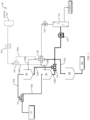
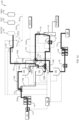
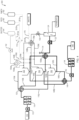
- the diafiltration system 100 further includes valves 132, 134, 136, and 138.
- Sample valve 132 can be toggled to control a flow of the sample through either of fluid conduits 116a, 116b such that the sample is routed to either the first cycling tank 102 or the second cycling tank 104.
- Buffer valve 134 can be toggled to control a flow of buffer solution from a buffer container 154 and a diafiltration pump 152 through either of fluid conduits 156a, 156b such that the buffer solution is delivered to either the first cycling tank 102 or the second cycling tank 104.
- valves 132, 134, 136, and 138 which can be switching valves or multiport valves, allow for a main product flow to be cycled between filling, diafiltration, and product recovery operations, while the diafiltration assembly 124 is operated continuously.
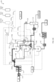
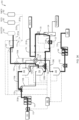
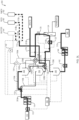
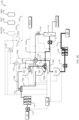
- FIGS. 3A-3N illustrate an example of a continuous diafiltration process using the system 200 of FIG. 2 .
- an initial pre-use membrane flush operation can be performed, as illustrated by bolded arrows 301a, 301b ( FIG. 3A ).
- the first, second, and third cleaning valves 172, 174, 176 are toggled to direct a flow of water from the container 180 through the continuous filtration assembly 124. With the retentate valve 138 closed along fluid conduits 128a, 128b, 128c and the cleaning valve 176 open, the water is directed to exit the system 200 following the membrane flush.
- holding tank 148 contains a volume sufficient for product recovery to begin
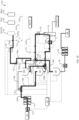
- flow of the sample is routed from holding tank 148, through the second filtration pump 142 and second filtration assembly 144, to the container 140, as shown by bolded arrow 310 ( FIG. 3I ).
- FIGS. 3I-3N upon initiation of product recovery from holding tank 148, outflow from the diafiltration system 200 can remain continuous until the sample completes processing.
- a rapid membrane regeneration process can be performed between diafiltration of sample batches, as shown by bolded arrows 313a-313d ( FIG. 3L ) in which the diafiltration assembly 124 is flushed and/or backflushed with buffer, water, and/or regeneration solution.
- Such regeneration process can occur without interruption of inflow and outflow from the system, as an inflow of sample can continue to be routed to one of the cycling tanks (for example, to the first cycling tank 102, as shown by bolded arrow 303a in FIG. 3L ) and an outflow of sample can continue to be routed away from holding tank 148 (as shown by bolded arrow 310).
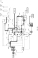
- diafiltration of a third batch of sample begins, with the sample being routed from, and buffer solution routed to, the first cycling tank 102, as shown by bolded arrows 304a, 304b ( FIG. 3M ).
- the system continues alternating the filling and continuous diafiltration of batches of the sample between cycle tanks 102 and 104.
- diafiltration assembly 124 can be in continuous operation. Additionally, inflow and outflow to and from the system (as shown by bolded arrows 303a, 303b, and 310) can also be continuous.
- the system 300 further includes an outlet valve 146 configured to control a flow of sample out of any of the three cycle tanks 102, 104, and 106.
- any of cycle tanks 102, 104 and 106 can store a batch of sample either prior to or following diafiltration, and diafiltration processes can cycle among the three tanks.
- TFF tangential flow filtration
- TFF assemblies can include cassettes, spiral-wound filter elements, capsules, or hollow-fiber filter elements.
- TFF provides an efficient method for performing buffer exchange while also enabling concentration of a sample in a same unit operation. As such, TFF is advantageous for use in diafiltration processes.
- systems of the present invention include TFF assemblies located upstream and/or downstream of the diafiltration assembly (e.g., filtration assemblies 114 and 144) to concentrate a sample prior to/following diafiltration.
- TFF assemblies can be single-pass TFF assemblies (SPTFF).
- SPTFF assemblies, and methods of using same following diafiltration, advantageously allow for higher product recoveries to be made through use of buffer flushing processes, as will be described further below. Without a final SPTFF step in a buffer flushing process, the recovered product would be diluted by excess buffer.
- diafiltration systems of the present invention include standard bioproduction equipment, such as conventional batch tanks, pumps, and control valves.
- the systems further include switching valves and/or multiport valves in fluid communication with the cycling tanks and diafiltration assembly to allow a main product flow to be cycled between filling, diafiltration, and product recovery operations while the diafiltration assembly is operated continuously.
- Systems and methods of the present invention advantageously allow smaller aliquots of product to undergo diafiltration, while providing for continuous production.
- process time, and hence number of pump passes can be shorter than typical batch diafiltration processes. It is desirable to limit the number of pump passes of the sample as biomolecules can be damaged while travelling through pumps and filtration equipment, which can result in a lower product yield. Additionally, such systems and methods can be used in-line with other processing operations, while also meeting high-buffer exchange requirements for bioprocessing operations.
- By breaking up a sample into multiple aliquots smaller cycle tanks and filtration assemblies may be used, providing for smaller system footprints and smaller cycle times.
- Buffer flushing can be performed by, for example, introducing a buffer solution, air, or gravity drain to push additional product located at or in the membrane of the diafiltration assembly, or in fluid conduits/piping, back to a current cycle tank (also referred to as back-flushing or flushing). The contents of the cycle tank are then provided as feed for a subsequent unit operation.
- a sample can first be pumped out of a cycle tank and then chased by a buffer solution into a separate product collection tank, the contents of which are subsequently provided as feed for the next unit operation.
- adequate time remains at the end of each diafiltration cycle to provide for a rapid regeneration cycle to be performed on the membrane, which can assist with maintaining constant diafiltration fluxes over extended cycling operations. Rapid regeneration cycles may not need to be performed following each diafiltration cycle, and can be invoked periodically or on an as-needed basis.
- the system undergoes a full or partial clean-in-place (CIP) procedure.
- CIP clean-in-place
- all or some of the fluid conduits and system components are replaced.
- TFF filtration assemblies that include single-use modules may have such modules removed and discarded, or cycling tanks that include single-use bags may have such bags discarded.
- Diafiltration can be performed by various control methods.
- continuous diafiltration processes are constant-volume diafiltration processes in which a total volume of the sample is maintained at a constant value throughout diafiltration.
- buffer is added to the cycle tank at a same rate that filtrate is removed.
- conventional batch diafiltration processes can be performed in which a large volume of diafiltration buffer is added to a cycle tank, and the sample undergoes repeated concentration filtration until a certain retentate volume is reached. When a certain retentate volume is reached, additional buffer is added, and the process repeats until a desired total volume of buffer has been added.
- continuous diafiltration processes of the present invention are optimum diafiltration processes.
- optimum diafiltration processes the volume and concentration of product are allowed to change along a controlled path throughout the process to optimize buffer use, product yield, and buffer exchange for a particular application.
- Optimum diafiltration processes may be particularly suited to operations in which removal of a component that is partially retained in the sample is desired, such as, for example, in a diafiltration process that, in addition to exchanging buffer, also involves separating proteins from a sample containing a nucleic acid product.
- TFF membrane crossflow can be controlled by adjusting a feed flow rate, a retentate flow rate, an average crossflow rate, and/or a pressure drop setpoint for a feed pump.
- TMP can be controlled by a retentate pressure control valve or by an overlay pressure applied to the cycle tank.
- a recirculating product volume can be controlled to either a constant set point (e.g., constant-volume diafiltration) or to a variable set point based on an algorithm that optimizes a concentration of the product and/or buffer species in the cycle tank (e.g., optimum diafiltration).
- Volume control can be monitored by a level probe or by load cells associated with the cycle tanks.
- flowmeters, totalizers, and/or weight scales can be used to measure a buffer addition flow rate and a permeate removal flow rate.
- Such measurements can be provided to a controller (e.g., controller 160), which can monitor the diafiltration process and effect adjustments to crossflow and TMP, such as by toggling valves or adjusting pump speeds.
- Endpoint control for diafiltration can also be effected by various endpoint control strategies.
- a diafiltration endpoint can be based on a totalized volume of diafiltration buffer added and/or a totalized volume of permeate removed, as measured by flow totalizers or weight scales located at or near fluid conduits and tanks of the system, or time based measurements.
- a diafiltration endpoint can be triggered based upon a measurable quality of the permeate or retentate stream that indicates an adequate buffer exchange has occurred.
- a diafiltration endpoint can be a solution adjustment such as conductivity reduction where the diafiltration is run to reduce the conductivity prior to a next step such as TFF or an ion exchange chromatography process.
- measurable qualities include pH, conductivity, refractive index, UV, turbidity, particle-size measurement, or near-real-time direct measurement of an excipient, impurity, or target product concentration (e.g., as determined by high-performance liquid chromatography (HPLC) or other analytical equipment) at-line or inline.
- HPLC high-performance liquid chromatography
- Product recovery can also be effected by various recovery strategies.
- flow rate and/or pump speed setpoints are monitored for a feed pump and/or diafiltration pump (e.g., pumps, 122, 152).
- a tank recovery endpoint is monitored and controlled based upon measured values obtained from level, weight, and/or air sensors, a measured volume totalization, a timed drain duration, or other means of sensing that a tank is empty.
- buffer flush recovery can be controlled by various recovery strategies.
- buffer flushing is monitored and controlled based upon a buffer pump flow rate, speed, and/or discharge pressure.
- a buffer flush endpoint can be triggered by a flush duration, totalized volume, recovery vessel of buffer vessel weight, an air sensor, or other measureable quality of the protein/buffer solution, such as an ultraviolet (UV) signal.
- UV ultraviolet
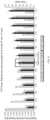
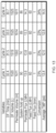
- Feed flow, retentate pressure, tank level, and diafiltration (DF) buffer addition were all successfully controlled to setpoint over the four cycles.
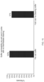
- Cycle times number of diavolumes, yields, final protein concentrations, and mass balances were consistent over all four cycles.
- the vessel used in the experiments has a lip which retains approximately 2 ml of volume, which cannot be recovered during tank recovery.
- that volume was not recovered after cycles 1 and 2 and was carried over to cycles 3 and 4, thus appearing as a tank residual in cycles 3 and 4.
- This volume was collected after cycles 3 and 4.
- the cycle yield the volume collected after cycles 3 and 4 was added to that of cycles 1 and 2.
- Tank designs can be optimized to improve drainability or a buffer addition recovery method can be performed.
Landscapes
- Engineering & Computer Science (AREA)
- Water Supply & Treatment (AREA)
- Chemical & Material Sciences (AREA)
- Chemical Kinetics & Catalysis (AREA)
- Separation Using Semi-Permeable Membranes (AREA)
- Medicines That Contain Protein Lipid Enzymes And Other Medicines (AREA)
Claims (18)
- Processus de filtration d'un échantillon liquide, comprenant :l'acheminement d'un premier lot d'un échantillon liquide depuis un récipient d'échantillon (110) vers un premier réservoir de cyclage (102) ;lors du remplissage du premier réservoir de cyclage (102), l'acheminement du premier lot de l'échantillon liquide depuis le premier réservoir de cyclage (102) vers un ensemble de diafiltration (124) par un processus de diafiltration continue qui comporte le réacheminement du rétentat produit par diafiltration du premier lot de l'échantillon liquide vers le premier réservoir de cyclage (102) ou, une fois qu'un point final de diafiltration est atteint, l'acheminement du rétentat vers un ensemble de filtration de concentration (144) ;pendant la diafiltration du premier lot de l'échantillon liquide, l'acheminement d'un deuxième lot de l'échantillon liquide depuis le récipient d'échantillon (110) vers un deuxième réservoir de cyclage (104) ;lors du remplissage du deuxième réservoir de cyclage (104), l'acheminement du deuxième lot de l'échantillon liquide depuis le deuxième réservoir de cyclage vers l'ensemble de diafiltration (124) par le processus de diafiltration continue qui comporte le réacheminement du rétentat produit par diafiltration du deuxième lot de l'échantillon liquide vers le deuxième réservoir de cyclage (104) ou, une fois qu'un point final de diafiltration est atteint, l'acheminement du rétentat vers un ensemble de filtration de concentration (144) ;la direction d'un flux de solution tampon vers le rétentat retournant au premier ou au deuxième réservoir de cyclage (102, 104) ; etla poursuite de l'alternance du remplissage et de la diafiltration continue des lots et de la vidange de l'échantillon liquide entre les premier (102) et deuxième (104) réservoirs de cyclage jusqu'à ce qu'un volume total de produit soit traité, dans lequel le processus de diafiltration continue comporte une étape de filtration tangentielle (TFF).
- Processus selon la revendication 1, dans lequel l'échantillon liquide est concentré avant d'être délivré au premier (102) ou au deuxième (104) réservoir de cyclage.
- Processus selon la revendication 1, comprenant en outre l'acheminement alterné du rétentat depuis les premier et deuxième lots d'échantillon liquide vers un réservoir de stockage (148) avant de délivrer le rétentat à l'ensemble de filtration de concentration.
- Processus selon la revendication 1, comprenant en outre la filtration alternée du rétentat produit par diafiltration continue du premier lot de l'échantillon liquide et du rétentat produit par diafiltration continue du deuxième lot de l'échantillon liquide à travers l'ensemble de filtration de concentration (144) jusqu'à ce qu'un volume total de produit soit récupéré.
- Processus selon la revendication 1, comprenant en outre le nettoyage de l'un des premier et deuxième réservoirs de cyclage (102, 104) pendant un processus de diafiltration continue au niveau de l'autre des premier et deuxième réservoirs de cyclage (102, 104).
- Processus selon la revendication 1, comprenant en outre le rinçage de l'ensemble de diafiltration (124) pendant le remplissage du premier ou du deuxième réservoir de cyclage.
- Processus selon la revendication 1, dans lequel le processus de diafiltration continue est un processus de diafiltration à volume constant ou un processus de diafiltration à volume optimal.
- Processus selon la revendication 1, comprenant en outre l'acheminement d'un troisième lot de l'échantillon liquide depuis le récipient d'échantillon vers un troisième réservoir de cyclage (106) et l'alternance du remplissage et de la diafiltration continue des lots de l'échantillon liquide parmi les premier, deuxième et troisième réservoirs de cyclage (102, 104, 106) jusqu'à ce qu'un volume total de produit soit récupéré.
- Processus selon la revendication 8, comprenant en outre l'acheminement du troisième lot de l'échantillon liquide depuis le troisième réservoir de cyclage (106) vers un second ensemble de diafiltration par un processus de diafiltration continue qui comporte le réacheminement du rétentat produit par diafiltration continue du troisième lot vers l'échantillon liquide vers le troisième réservoir de cyclage (106) ou vers l'ensemble de filtration de concentration (144) pour la récupération du produit, dans lequel les ensembles de diafiltration sont configurés pour fonctionner en parallèle.
- Système (100) de filtration d'un échantillon liquide, comprenant :des premier et deuxième réservoirs de cyclage (102, 104) ;une première vanne (132) configurée pour diriger un flux d'un échantillon liquide vers le premier ou le deuxième réservoir de cyclage (102, 104) ;un ensemble de diafiltration (124) ;une deuxième vanne (136) configurée pour diriger l'échantillon liquide vers l'ensemble de diafiltration depuis le premier ou le deuxième réservoir de cyclage ;une pompe de diafiltration (152) en communication fluidique avec un réservoir tampon de diafiltration (154) et les premier et deuxième réservoirs de cyclage (102, 104), ou en communication fluidique avec un conduit de fluide configuré pour diriger le rétentat vers les premier et deuxième réservoirs de cyclage (102, 104) ;une troisième vanne (134) configurée pour diriger un flux de solution tampon vers le rétentat de l'ensemble de diafiltration retournant au premier ou au deuxième réservoir de cyclage (102, 104) ; etun dispositif de commande (160) configuré pour faire basculer la première vanne (132) afin de diriger alternativement l'échantillon liquide vers l'un des premier et deuxième réservoirs de cyclage (102, 104) tout en faisant basculer les deuxième et troisième vannes (136, 134) pour diriger l'échantillon liquide vers l'ensemble de diafiltration (124) depuis, et la solution tampon vers le rétentat retournant à,l'autre des premier et deuxième réservoirs de cyclage (102, 104) à travers un processus de diafiltration continue dans lequel l'ensemble de diafiltration (124) comprend un ensemble de filtration tangentielle (TFF).
- Système selon la revendication 10, comprenant en outre :un ensemble de filtration tangentielle à passage unique (SPTFF) (114) en amont des premier et deuxième réservoirs de cyclage (102, 104) ; ouun ensemble de filtration tangentielle à passage unique (SPTFF) en aval des premier et deuxième réservoirs de diafiltration.
- Système selon la revendication 10, comprenant en outre un réservoir de stockage (148) en aval des premier et deuxième réservoirs de cyclage (102, 104).
- Système selon la revendication 10, comprenant en outre un troisième réservoir de cyclage (106), dans lequel le dispositif de commande (160) est en outre configuré pour faire circuler des lots de l'échantillon liquide parmi les premier, deuxième et troisième réservoirs de cyclage (102, 104, 106) dans le processus de diafiltration continue au niveau de l'ensemble de diafiltration (124).
- Système selon la revendication 13, comprenant en outre un second ensemble de diafiltration configuré pour fonctionner en parallèle avec le premier ensemble de diafiltration (124), dans lequel le dispositif de commande (160) est en outre configuré pour faire circuler des lots de l'échantillon liquide parmi les premier, deuxième et troisième réservoirs de cyclage (102, 104, 106) dans un processus de diafiltration continue au niveau des deux ensembles de diafiltration.
- Système selon la revendication 10, comprenant en outre une pompe d'alimentation (122) en communication fluidique avec les premier et deuxième réservoirs de cyclage (102, 104) et l'ensemble de diafiltration (124), dans lequel le dispositif de commande (160) est en outre configuré pour commander un taux de flux de l'échantillon liquide au niveau de la pompe d'alimentation (122).
- Processus de filtration d'un échantillon liquide, comprenant :l'acheminement d'un premier lot d'un échantillon liquide depuis un récipient d'échantillon (110) vers un premier réservoir de cyclage (102) ;lors du remplissage du premier réservoir de cyclage (102), l'acheminement du premier lot de l'échantillon liquide depuis le premier réservoir de cyclage (102) vers un ensemble de diafiltration (124) par un processus de diafiltration continue qui comporte le réacheminement du rétentat produit par diafiltration du premier lot de l'échantillon liquide vers le premier réservoir de cyclage (102) ou, une fois qu'un point final de diafiltration est atteint, l'acheminement du rétentat vers un vaisseau d'extraction (140) ;pendant la diafiltration du premier lot de l'échantillon liquide, l'acheminement d'un deuxième lot de l'échantillon liquide depuis le récipient d'échantillon (110) vers un deuxième réservoir de cyclage (104) ;lors du remplissage du deuxième réservoir de cyclage (104), l'acheminement du deuxième lot de l'échantillon liquide depuis le deuxième réservoir de cyclage (104) vers l'ensemble de diafiltration (104) par le processus de diafiltration continue qui comporte le réacheminement du rétentat produit par diafiltration du deuxième lot de l'échantillon liquide vers le deuxième réservoir de cyclage (104) ou, une fois qu'un point final de diafiltration est atteint, l'acheminement du rétentat vers un vaisseau d'extraction (140) ;la direction d'un flux de solution tampon vers le rétentat retournant au premier ou au deuxième réservoir de cyclage (102, 104) ; etla poursuite de l'alternance du remplissage et de la diafiltration continue des lots et de la vidange de l'échantillon liquide entre les premier et deuxième réservoirs de cyclage (102, 104) jusqu'à ce qu'un volume total de produit soit traité, dans lequel le processus de diafiltration continue comporte une étape de filtration tangentielle (TFF).
- Processus selon la revendication 16, dans lequel le vaisseau d'extraction (140) est un récipient de produit final destiné à être utilisé par un utilisateur final.
- Système selon la revendication 10, dans lequel le dispositif de commande (160) est en outre configuré pour commander la distribution de tampon sur la base du taux de flux de la solution tampon au niveau de la pompe de diafiltration, de la durée de vie du perméat, de la concentration optimale de diafiltration ou du niveau de l'un quelconque des réservoirs de cyclage.
Applications Claiming Priority (2)
| Application Number | Priority Date | Filing Date | Title |
|---|---|---|---|
| US201762585132P | 2017-11-13 | 2017-11-13 | |
| PCT/US2018/058660 WO2019094249A1 (fr) | 2017-11-13 | 2018-11-01 | Diafiltration continue au moyen d'un cyclage de réservoir |
Publications (2)
| Publication Number | Publication Date |
|---|---|
| EP3710141A1 EP3710141A1 (fr) | 2020-09-23 |
| EP3710141B1 true EP3710141B1 (fr) | 2024-07-03 |
Family
ID=64362696
Family Applications (1)
| Application Number | Title | Priority Date | Filing Date |
|---|---|---|---|
| EP18804820.1A Active EP3710141B1 (fr) | 2017-11-13 | 2018-11-01 | Diafiltration continue au moyen d'un cyclage de réservoir |
Country Status (10)
| Country | Link |
|---|---|
| US (2) | US11691107B2 (fr) |
| EP (1) | EP3710141B1 (fr) |
| JP (1) | JP7177154B2 (fr) |
| KR (2) | KR20220050232A (fr) |
| CN (1) | CN111246930B (fr) |
| CA (1) | CA3080724C (fr) |
| ES (1) | ES2995480T3 (fr) |
| SG (1) | SG11202001497PA (fr) |
| TW (2) | TWI753216B (fr) |
| WO (1) | WO2019094249A1 (fr) |
Families Citing this family (13)
| Publication number | Priority date | Publication date | Assignee | Title |
|---|---|---|---|---|
| CN111246930B (zh) | 2017-11-13 | 2022-12-02 | Emd密理博公司 | 通过罐循环的连续透滤 |
| WO2020030629A1 (fr) * | 2018-08-07 | 2020-02-13 | Merz Pharma Gmbh & Co. Kgaa | Procédé de filtration dynamique d'un hydrogel réticulé |
| US11241656B2 (en) * | 2018-11-29 | 2022-02-08 | Watersep Bioseparations Llc | Single pass cross flow diafiltration module and method |
| EP3939691B1 (fr) * | 2020-07-13 | 2023-11-22 | Sartorius Stedim Biotech GmbH | Dispositif d'assemblage de production de bio-conjugués |
| EP4182427A1 (fr) * | 2020-07-15 | 2023-05-24 | Global Life Sciences Solutions USA LLC | Système de perfusion de biotraitement ayant une pluralité de filtres, et procédé de fonctionnement |
| WO2022076318A1 (fr) * | 2020-10-05 | 2022-04-14 | Bristol-Myers Squibb Company | Procédés pour concentrer des protéines |
| WO2022251261A1 (fr) * | 2021-05-25 | 2022-12-01 | Boehringer Ingelheim International Gmbh | Procédé et système intégrés et continus de filtration et de concentration virales et d'échange de tampon |
| CN118922240A (zh) * | 2022-03-21 | 2024-11-08 | 瑞普利金公司 | 基于可变路径长度uv光谱的自动tff系统 |
| AU2023275760A1 (en) * | 2022-05-26 | 2024-12-05 | Eli Lilly And Company | Continuous tangential flow filtration system |
| WO2024138152A1 (fr) * | 2022-12-23 | 2024-06-27 | Asahi Kasei Bioprocess America, Inc. | Système pour effectuer des opérations de clivage, de déprotection, d'ultrafiltration et de diafiltration |
| IT202300017964A1 (it) * | 2023-08-31 | 2025-03-03 | Antoni Bellussi | Impianto di filtrazione di sostanze semisolide e liquide di vario genere e metodo di funzonamento di tale impianto |
| WO2025087829A1 (fr) * | 2023-10-24 | 2025-05-01 | Merck Patent Gmbh | Filtration continue au moyen d'un cyclage d'alimentation |
| SE2450213A1 (en) * | 2024-02-20 | 2025-06-17 | Helios Innovations AB | Method and system for managing process fluid |
Family Cites Families (14)
| Publication number | Priority date | Publication date | Assignee | Title |
|---|---|---|---|---|
| US5871652A (en) | 1995-08-04 | 1999-02-16 | Pipetronics, Inc. | Method for high volume pipeline water filtration |
| JP2000126767A (ja) * | 1998-10-21 | 2000-05-09 | Toray Ind Inc | 精製水の製造方法および装置 |
| US7510654B2 (en) * | 2005-12-29 | 2009-03-31 | Spf Innovations, Llc | Method and apparatus for the filtration of biological samples |
| JP4805201B2 (ja) * | 2007-03-22 | 2011-11-02 | 月島環境エンジニアリング株式会社 | 膜分離を用いた目的物質の分離方法と装置 |
| US8808538B2 (en) | 2008-01-04 | 2014-08-19 | Fluid Equipment Development Company, Llc | Batch-operated reverse osmosis system |
| EP2393579B1 (fr) | 2009-01-21 | 2017-03-08 | Smartflow Technologies, Inc. | Optimisation de la séparation pour des suspensions visqueuses |
| EP2644259A1 (fr) * | 2012-03-29 | 2013-10-02 | Roche Diagniostics GmbH | Système de filtration à micro-écoulement et procédé de filtration d'écoulement |
| EP2682168A1 (fr) * | 2012-07-02 | 2014-01-08 | Millipore Corporation | Dispositif de tirage et métier à filer |
| US9695393B2 (en) * | 2012-08-20 | 2017-07-04 | Terumo Bct, Inc. | Concentrating components of fluid circulated through a cell growth chamber |
| US9770804B2 (en) * | 2013-03-18 | 2017-09-26 | Versum Materials Us, Llc | Slurry supply and/or chemical blend supply apparatuses, processes, methods of use and methods of manufacture |
| US9821274B1 (en) * | 2014-02-09 | 2017-11-21 | Spf Innovations Llc | Hybrid diafiltration system and methods |
| KR20160133489A (ko) * | 2014-03-07 | 2016-11-22 | 에이전시 포 사이언스, 테크놀로지 앤드 리서치 | 생물학적 생성물들의 제조를 위한 장치 및 방법들 |
| CN105745009B (zh) | 2014-08-29 | 2018-09-28 | Emd 密理博公司 | 单程切向流过滤系统和具有渗余物的再循环的切向流过滤系统 |
| CN111246930B (zh) | 2017-11-13 | 2022-12-02 | Emd密理博公司 | 通过罐循环的连续透滤 |
-
2018
- 2018-11-01 CN CN201880068067.5A patent/CN111246930B/zh active Active
- 2018-11-01 CA CA3080724A patent/CA3080724C/fr active Active
- 2018-11-01 JP JP2020522302A patent/JP7177154B2/ja active Active
- 2018-11-01 US US16/762,688 patent/US11691107B2/en active Active
- 2018-11-01 SG SG11202001497PA patent/SG11202001497PA/en unknown
- 2018-11-01 ES ES18804820T patent/ES2995480T3/es active Active
- 2018-11-01 WO PCT/US2018/058660 patent/WO2019094249A1/fr not_active Ceased
- 2018-11-01 KR KR1020227011789A patent/KR20220050232A/ko not_active Ceased
- 2018-11-01 KR KR1020207013242A patent/KR102386215B1/ko active Active
- 2018-11-01 EP EP18804820.1A patent/EP3710141B1/fr active Active
- 2018-11-05 TW TW107139122A patent/TWI753216B/zh active
- 2018-11-05 TW TW111103761A patent/TWI788212B/zh active
-
2023
- 2023-03-14 US US18/183,609 patent/US12128359B2/en active Active
Non-Patent Citations (1)
| Title |
|---|
| LUTZ H: "Ultrafiltration: Fundamentals and Engineering", COMPREHENSIVE MEMBRANE SCIENCE AND ENGINEERING,, vol. 2, 1 January 2010 (2010-01-01), pages 115 - 139, XP009154484, DOI: 10.1016/B978-0-08-093250-7.00037-2 * |
Also Published As
| Publication number | Publication date |
|---|---|
| JP7177154B2 (ja) | 2022-11-22 |
| CN111246930B (zh) | 2022-12-02 |
| JP2021502232A (ja) | 2021-01-28 |
| SG11202001497PA (en) | 2020-03-30 |
| TWI753216B (zh) | 2022-01-21 |
| WO2019094249A1 (fr) | 2019-05-16 |
| US11691107B2 (en) | 2023-07-04 |
| KR102386215B1 (ko) | 2022-04-15 |
| KR20220050232A (ko) | 2022-04-22 |
| EP3710141A1 (fr) | 2020-09-23 |
| TW201922305A (zh) | 2019-06-16 |
| KR20200060765A (ko) | 2020-06-01 |
| US20230211291A1 (en) | 2023-07-06 |
| CA3080724C (fr) | 2023-04-25 |
| US12128359B2 (en) | 2024-10-29 |
| TW202220708A (zh) | 2022-06-01 |
| TWI788212B (zh) | 2022-12-21 |
| US20210170336A1 (en) | 2021-06-10 |
| ES2995480T3 (en) | 2025-02-10 |
| CN111246930A (zh) | 2020-06-05 |
| CA3080724A1 (fr) | 2019-05-16 |
Similar Documents
| Publication | Publication Date | Title |
|---|---|---|
| US12128359B2 (en) | Continuous diafiltration by means of tank cycling | |
| US11679349B2 (en) | Single pass tangential flow filtration systems and tangential flow filtration systems with recirculation of retentate | |
| US11040310B2 (en) | Single-pass filtration systems and processes | |
| WO2025087829A1 (fr) | Filtration continue au moyen d'un cyclage d'alimentation | |
| EP2957335A1 (fr) | Systèmes et processus de filtration monopasse | |
| EP4144434B1 (fr) | Systèmes et procédés de filtration à passage unique |
Legal Events
| Date | Code | Title | Description |
|---|---|---|---|
| STAA | Information on the status of an ep patent application or granted ep patent |
Free format text: STATUS: UNKNOWN |
|
| STAA | Information on the status of an ep patent application or granted ep patent |
Free format text: STATUS: THE INTERNATIONAL PUBLICATION HAS BEEN MADE |
|
| PUAI | Public reference made under article 153(3) epc to a published international application that has entered the european phase |
Free format text: ORIGINAL CODE: 0009012 |
|
| STAA | Information on the status of an ep patent application or granted ep patent |
Free format text: STATUS: REQUEST FOR EXAMINATION WAS MADE |
|
| 17P | Request for examination filed |
Effective date: 20200318 |
|
| AK | Designated contracting states |
Kind code of ref document: A1 Designated state(s): AL AT BE BG CH CY CZ DE DK EE ES FI FR GB GR HR HU IE IS IT LI LT LU LV MC MK MT NL NO PL PT RO RS SE SI SK SM TR |
|
| AX | Request for extension of the european patent |
Extension state: BA ME |
|
| DAV | Request for validation of the european patent (deleted) | ||
| DAX | Request for extension of the european patent (deleted) | ||
| STAA | Information on the status of an ep patent application or granted ep patent |
Free format text: STATUS: EXAMINATION IS IN PROGRESS |
|
| 17Q | First examination report despatched |
Effective date: 20211104 |
|
| P01 | Opt-out of the competence of the unified patent court (upc) registered |
Effective date: 20230602 |
|
| GRAP | Despatch of communication of intention to grant a patent |
Free format text: ORIGINAL CODE: EPIDOSNIGR1 |
|
| STAA | Information on the status of an ep patent application or granted ep patent |
Free format text: STATUS: GRANT OF PATENT IS INTENDED |
|
| INTG | Intention to grant announced |
Effective date: 20240215 |
|
| GRAS | Grant fee paid |
Free format text: ORIGINAL CODE: EPIDOSNIGR3 |
|
| GRAA | (expected) grant |
Free format text: ORIGINAL CODE: 0009210 |
|
| STAA | Information on the status of an ep patent application or granted ep patent |
Free format text: STATUS: THE PATENT HAS BEEN GRANTED |
|
| AK | Designated contracting states |
Kind code of ref document: B1 Designated state(s): AL AT BE BG CH CY CZ DE DK EE ES FI FR GB GR HR HU IE IS IT LI LT LU LV MC MK MT NL NO PL PT RO RS SE SI SK SM TR |
|
| REG | Reference to a national code |
Ref country code: CH Ref legal event code: EP |
|
| REG | Reference to a national code |
Ref country code: DE Ref legal event code: R096 Ref document number: 602018071354 Country of ref document: DE |
|
| REG | Reference to a national code |
Ref country code: NL Ref legal event code: FP |
|
| REG | Reference to a national code |
Ref country code: LT Ref legal event code: MG9D |
|
| PG25 | Lapsed in a contracting state [announced via postgrant information from national office to epo] |
Ref country code: PT Free format text: LAPSE BECAUSE OF FAILURE TO SUBMIT A TRANSLATION OF THE DESCRIPTION OR TO PAY THE FEE WITHIN THE PRESCRIBED TIME-LIMIT Effective date: 20241104 |
|
| REG | Reference to a national code |
Ref country code: AT Ref legal event code: MK05 Ref document number: 1699245 Country of ref document: AT Kind code of ref document: T Effective date: 20240703 |
|
| PG25 | Lapsed in a contracting state [announced via postgrant information from national office to epo] |
Ref country code: PT Free format text: LAPSE BECAUSE OF FAILURE TO SUBMIT A TRANSLATION OF THE DESCRIPTION OR TO PAY THE FEE WITHIN THE PRESCRIBED TIME-LIMIT Effective date: 20241104 |
|
| PG25 | Lapsed in a contracting state [announced via postgrant information from national office to epo] |
Ref country code: NO Free format text: LAPSE BECAUSE OF FAILURE TO SUBMIT A TRANSLATION OF THE DESCRIPTION OR TO PAY THE FEE WITHIN THE PRESCRIBED TIME-LIMIT Effective date: 20241003 |
|
| PG25 | Lapsed in a contracting state [announced via postgrant information from national office to epo] |
Ref country code: GR Free format text: LAPSE BECAUSE OF FAILURE TO SUBMIT A TRANSLATION OF THE DESCRIPTION OR TO PAY THE FEE WITHIN THE PRESCRIBED TIME-LIMIT Effective date: 20241004 Ref country code: FI Free format text: LAPSE BECAUSE OF FAILURE TO SUBMIT A TRANSLATION OF THE DESCRIPTION OR TO PAY THE FEE WITHIN THE PRESCRIBED TIME-LIMIT Effective date: 20240703 Ref country code: PL Free format text: LAPSE BECAUSE OF FAILURE TO SUBMIT A TRANSLATION OF THE DESCRIPTION OR TO PAY THE FEE WITHIN THE PRESCRIBED TIME-LIMIT Effective date: 20240703 |
|
| PG25 | Lapsed in a contracting state [announced via postgrant information from national office to epo] |
Ref country code: BG Free format text: LAPSE BECAUSE OF FAILURE TO SUBMIT A TRANSLATION OF THE DESCRIPTION OR TO PAY THE FEE WITHIN THE PRESCRIBED TIME-LIMIT Effective date: 20240703 |
|
| PG25 | Lapsed in a contracting state [announced via postgrant information from national office to epo] |
Ref country code: LV Free format text: LAPSE BECAUSE OF FAILURE TO SUBMIT A TRANSLATION OF THE DESCRIPTION OR TO PAY THE FEE WITHIN THE PRESCRIBED TIME-LIMIT Effective date: 20240703 |
|
| PG25 | Lapsed in a contracting state [announced via postgrant information from national office to epo] |
Ref country code: IS Free format text: LAPSE BECAUSE OF FAILURE TO SUBMIT A TRANSLATION OF THE DESCRIPTION OR TO PAY THE FEE WITHIN THE PRESCRIBED TIME-LIMIT Effective date: 20241103 Ref country code: AT Free format text: LAPSE BECAUSE OF FAILURE TO SUBMIT A TRANSLATION OF THE DESCRIPTION OR TO PAY THE FEE WITHIN THE PRESCRIBED TIME-LIMIT Effective date: 20240703 |
|
| PG25 | Lapsed in a contracting state [announced via postgrant information from national office to epo] |
Ref country code: HR Free format text: LAPSE BECAUSE OF FAILURE TO SUBMIT A TRANSLATION OF THE DESCRIPTION OR TO PAY THE FEE WITHIN THE PRESCRIBED TIME-LIMIT Effective date: 20240703 Ref country code: CZ Free format text: LAPSE BECAUSE OF FAILURE TO SUBMIT A TRANSLATION OF THE DESCRIPTION OR TO PAY THE FEE WITHIN THE PRESCRIBED TIME-LIMIT Effective date: 20240703 |
|
| PG25 | Lapsed in a contracting state [announced via postgrant information from national office to epo] |
Ref country code: RS Free format text: LAPSE BECAUSE OF FAILURE TO SUBMIT A TRANSLATION OF THE DESCRIPTION OR TO PAY THE FEE WITHIN THE PRESCRIBED TIME-LIMIT Effective date: 20241003 |
|
| PG25 | Lapsed in a contracting state [announced via postgrant information from national office to epo] |
Ref country code: RS Free format text: LAPSE BECAUSE OF FAILURE TO SUBMIT A TRANSLATION OF THE DESCRIPTION OR TO PAY THE FEE WITHIN THE PRESCRIBED TIME-LIMIT Effective date: 20241003 Ref country code: PL Free format text: LAPSE BECAUSE OF FAILURE TO SUBMIT A TRANSLATION OF THE DESCRIPTION OR TO PAY THE FEE WITHIN THE PRESCRIBED TIME-LIMIT Effective date: 20240703 Ref country code: NO Free format text: LAPSE BECAUSE OF FAILURE TO SUBMIT A TRANSLATION OF THE DESCRIPTION OR TO PAY THE FEE WITHIN THE PRESCRIBED TIME-LIMIT Effective date: 20241003 Ref country code: LV Free format text: LAPSE BECAUSE OF FAILURE TO SUBMIT A TRANSLATION OF THE DESCRIPTION OR TO PAY THE FEE WITHIN THE PRESCRIBED TIME-LIMIT Effective date: 20240703 Ref country code: IS Free format text: LAPSE BECAUSE OF FAILURE TO SUBMIT A TRANSLATION OF THE DESCRIPTION OR TO PAY THE FEE WITHIN THE PRESCRIBED TIME-LIMIT Effective date: 20241103 Ref country code: HR Free format text: LAPSE BECAUSE OF FAILURE TO SUBMIT A TRANSLATION OF THE DESCRIPTION OR TO PAY THE FEE WITHIN THE PRESCRIBED TIME-LIMIT Effective date: 20240703 Ref country code: GR Free format text: LAPSE BECAUSE OF FAILURE TO SUBMIT A TRANSLATION OF THE DESCRIPTION OR TO PAY THE FEE WITHIN THE PRESCRIBED TIME-LIMIT Effective date: 20241004 Ref country code: FI Free format text: LAPSE BECAUSE OF FAILURE TO SUBMIT A TRANSLATION OF THE DESCRIPTION OR TO PAY THE FEE WITHIN THE PRESCRIBED TIME-LIMIT Effective date: 20240703 Ref country code: CZ Free format text: LAPSE BECAUSE OF FAILURE TO SUBMIT A TRANSLATION OF THE DESCRIPTION OR TO PAY THE FEE WITHIN THE PRESCRIBED TIME-LIMIT Effective date: 20240703 Ref country code: BG Free format text: LAPSE BECAUSE OF FAILURE TO SUBMIT A TRANSLATION OF THE DESCRIPTION OR TO PAY THE FEE WITHIN THE PRESCRIBED TIME-LIMIT Effective date: 20240703 Ref country code: AT Free format text: LAPSE BECAUSE OF FAILURE TO SUBMIT A TRANSLATION OF THE DESCRIPTION OR TO PAY THE FEE WITHIN THE PRESCRIBED TIME-LIMIT Effective date: 20240703 |
|
| REG | Reference to a national code |
Ref country code: ES Ref legal event code: FG2A Ref document number: 2995480 Country of ref document: ES Kind code of ref document: T3 Effective date: 20250210 |
|
| REG | Reference to a national code |
Ref country code: DE Ref legal event code: R097 Ref document number: 602018071354 Country of ref document: DE |
|
| PG25 | Lapsed in a contracting state [announced via postgrant information from national office to epo] |
Ref country code: DK Free format text: LAPSE BECAUSE OF FAILURE TO SUBMIT A TRANSLATION OF THE DESCRIPTION OR TO PAY THE FEE WITHIN THE PRESCRIBED TIME-LIMIT Effective date: 20240703 Ref country code: RO Free format text: LAPSE BECAUSE OF FAILURE TO SUBMIT A TRANSLATION OF THE DESCRIPTION OR TO PAY THE FEE WITHIN THE PRESCRIBED TIME-LIMIT Effective date: 20240703 Ref country code: SM Free format text: LAPSE BECAUSE OF FAILURE TO SUBMIT A TRANSLATION OF THE DESCRIPTION OR TO PAY THE FEE WITHIN THE PRESCRIBED TIME-LIMIT Effective date: 20240703 |
|
| PG25 | Lapsed in a contracting state [announced via postgrant information from national office to epo] |
Ref country code: EE Free format text: LAPSE BECAUSE OF FAILURE TO SUBMIT A TRANSLATION OF THE DESCRIPTION OR TO PAY THE FEE WITHIN THE PRESCRIBED TIME-LIMIT Effective date: 20240703 |
|
| PG25 | Lapsed in a contracting state [announced via postgrant information from national office to epo] |
Ref country code: SK Free format text: LAPSE BECAUSE OF FAILURE TO SUBMIT A TRANSLATION OF THE DESCRIPTION OR TO PAY THE FEE WITHIN THE PRESCRIBED TIME-LIMIT Effective date: 20240703 |
|
| PLBE | No opposition filed within time limit |
Free format text: ORIGINAL CODE: 0009261 |
|
| STAA | Information on the status of an ep patent application or granted ep patent |
Free format text: STATUS: NO OPPOSITION FILED WITHIN TIME LIMIT |
|
| 26N | No opposition filed |
Effective date: 20250404 |
|
| PG25 | Lapsed in a contracting state [announced via postgrant information from national office to epo] |
Ref country code: MC Free format text: LAPSE BECAUSE OF FAILURE TO SUBMIT A TRANSLATION OF THE DESCRIPTION OR TO PAY THE FEE WITHIN THE PRESCRIBED TIME-LIMIT Effective date: 20240703 |
|
| PG25 | Lapsed in a contracting state [announced via postgrant information from national office to epo] |
Ref country code: LU Free format text: LAPSE BECAUSE OF NON-PAYMENT OF DUE FEES Effective date: 20241101 |
|
| PG25 | Lapsed in a contracting state [announced via postgrant information from national office to epo] |
Ref country code: SE Free format text: LAPSE BECAUSE OF FAILURE TO SUBMIT A TRANSLATION OF THE DESCRIPTION OR TO PAY THE FEE WITHIN THE PRESCRIBED TIME-LIMIT Effective date: 20240703 |
|
| PGFP | Annual fee paid to national office [announced via postgrant information from national office to epo] |
Ref country code: NL Payment date: 20251022 Year of fee payment: 8 |
|
| REG | Reference to a national code |
Ref country code: CH Ref legal event code: U11 Free format text: ST27 STATUS EVENT CODE: U-0-0-U10-U11 (AS PROVIDED BY THE NATIONAL OFFICE) Effective date: 20251201 |
|
| PGFP | Annual fee paid to national office [announced via postgrant information from national office to epo] |
Ref country code: DE Payment date: 20251022 Year of fee payment: 8 |
|
| PGFP | Annual fee paid to national office [announced via postgrant information from national office to epo] |
Ref country code: GB Payment date: 20251023 Year of fee payment: 8 |
|
| PGFP | Annual fee paid to national office [announced via postgrant information from national office to epo] |
Ref country code: IT Payment date: 20251022 Year of fee payment: 8 |
|
| PGFP | Annual fee paid to national office [announced via postgrant information from national office to epo] |
Ref country code: FR Payment date: 20251023 Year of fee payment: 8 |
|
| PGFP | Annual fee paid to national office [announced via postgrant information from national office to epo] |
Ref country code: BE Payment date: 20251022 Year of fee payment: 8 |
|
| PGFP | Annual fee paid to national office [announced via postgrant information from national office to epo] |
Ref country code: CH Payment date: 20251201 Year of fee payment: 8 |
|
| PGFP | Annual fee paid to national office [announced via postgrant information from national office to epo] |
Ref country code: IE Payment date: 20251024 Year of fee payment: 8 |
|
| PGFP | Annual fee paid to national office [announced via postgrant information from national office to epo] |
Ref country code: ES Payment date: 20251201 Year of fee payment: 8 |
|
| PG25 | Lapsed in a contracting state [announced via postgrant information from national office to epo] |
Ref country code: HU Free format text: LAPSE BECAUSE OF FAILURE TO SUBMIT A TRANSLATION OF THE DESCRIPTION OR TO PAY THE FEE WITHIN THE PRESCRIBED TIME-LIMIT; INVALID AB INITIO Effective date: 20181101 |
|
| PG25 | Lapsed in a contracting state [announced via postgrant information from national office to epo] |
Ref country code: CY Free format text: LAPSE BECAUSE OF FAILURE TO SUBMIT A TRANSLATION OF THE DESCRIPTION OR TO PAY THE FEE WITHIN THE PRESCRIBED TIME-LIMIT; INVALID AB INITIO Effective date: 20181101 |