EP3710168B1 - Filtering fluid dispensing device - Google Patents
Filtering fluid dispensing device Download PDFInfo
- Publication number
- EP3710168B1 EP3710168B1 EP18812528.0A EP18812528A EP3710168B1 EP 3710168 B1 EP3710168 B1 EP 3710168B1 EP 18812528 A EP18812528 A EP 18812528A EP 3710168 B1 EP3710168 B1 EP 3710168B1
- Authority
- EP
- European Patent Office
- Prior art keywords
- entrance
- force applying
- applying element
- end plate
- spool
- Prior art date
- Legal status (The legal status is an assumption and is not a legal conclusion. Google has not performed a legal analysis and makes no representation as to the accuracy of the status listed.)
- Active
Links
Images



Classifications
-
- B—PERFORMING OPERATIONS; TRANSPORTING
- B05—SPRAYING OR ATOMISING IN GENERAL; APPLYING FLUENT MATERIALS TO SURFACES, IN GENERAL
- B05B—SPRAYING APPARATUS; ATOMISING APPARATUS; NOZZLES
- B05B7/00—Spraying apparatus for discharge of liquids or other fluent materials from two or more sources, e.g. of liquid and air, of powder and gas
- B05B7/02—Spray pistols; Apparatus for discharge
- B05B7/12—Spray pistols; Apparatus for discharge designed to control volume of flow, e.g. with adjustable passages
- B05B7/1209—Spray pistols; Apparatus for discharge designed to control volume of flow, e.g. with adjustable passages the controlling means for each liquid or other fluent material being manual and interdependent
-
- B—PERFORMING OPERATIONS; TRANSPORTING
- B05—SPRAYING OR ATOMISING IN GENERAL; APPLYING FLUENT MATERIALS TO SURFACES, IN GENERAL
- B05B—SPRAYING APPARATUS; ATOMISING APPARATUS; NOZZLES
- B05B1/00—Nozzles, spray heads or other outlets, with or without auxiliary devices such as valves, heating means
- B05B1/30—Nozzles, spray heads or other outlets, with or without auxiliary devices such as valves, heating means designed to control volume of flow, e.g. with adjustable passages
- B05B1/3026—Gate valves; Sliding valves; Cocks
-
- B—PERFORMING OPERATIONS; TRANSPORTING
- B05—SPRAYING OR ATOMISING IN GENERAL; APPLYING FLUENT MATERIALS TO SURFACES, IN GENERAL
- B05B—SPRAYING APPARATUS; ATOMISING APPARATUS; NOZZLES
- B05B12/00—Arrangements for controlling delivery; Arrangements for controlling the spray area
- B05B12/002—Manually-actuated controlling means, e.g. push buttons, levers or triggers
-
- B—PERFORMING OPERATIONS; TRANSPORTING
- B05—SPRAYING OR ATOMISING IN GENERAL; APPLYING FLUENT MATERIALS TO SURFACES, IN GENERAL
- B05B—SPRAYING APPARATUS; ATOMISING APPARATUS; NOZZLES
- B05B15/00—Details of spraying plant or spraying apparatus not otherwise provided for; Accessories
- B05B15/40—Filters located upstream of the spraying outlets
-
- B—PERFORMING OPERATIONS; TRANSPORTING
- B05—SPRAYING OR ATOMISING IN GENERAL; APPLYING FLUENT MATERIALS TO SURFACES, IN GENERAL
- B05B—SPRAYING APPARATUS; ATOMISING APPARATUS; NOZZLES
- B05B7/00—Spraying apparatus for discharge of liquids or other fluent materials from two or more sources, e.g. of liquid and air, of powder and gas
- B05B7/0018—Spraying apparatus for discharge of liquids or other fluent materials from two or more sources, e.g. of liquid and air, of powder and gas with devices for making foam
- B05B7/0025—Spraying apparatus for discharge of liquids or other fluent materials from two or more sources, e.g. of liquid and air, of powder and gas with devices for making foam with a compressed gas supply
-
- B—PERFORMING OPERATIONS; TRANSPORTING
- B05—SPRAYING OR ATOMISING IN GENERAL; APPLYING FLUENT MATERIALS TO SURFACES, IN GENERAL
- B05B—SPRAYING APPARATUS; ATOMISING APPARATUS; NOZZLES
- B05B7/00—Spraying apparatus for discharge of liquids or other fluent materials from two or more sources, e.g. of liquid and air, of powder and gas
- B05B7/24—Spraying apparatus for discharge of liquids or other fluent materials from two or more sources, e.g. of liquid and air, of powder and gas with means, e.g. a container, for supplying liquid or other fluent material to a discharge device
- B05B7/2489—Spraying apparatus for discharge of liquids or other fluent materials from two or more sources, e.g. of liquid and air, of powder and gas with means, e.g. a container, for supplying liquid or other fluent material to a discharge device an atomising fluid, e.g. a gas, being supplied to the discharge device
- B05B7/2497—Spraying apparatus for discharge of liquids or other fluent materials from two or more sources, e.g. of liquid and air, of powder and gas with means, e.g. a container, for supplying liquid or other fluent material to a discharge device an atomising fluid, e.g. a gas, being supplied to the discharge device several liquids from different sources being supplied to the discharge device
-
- B—PERFORMING OPERATIONS; TRANSPORTING
- B05—SPRAYING OR ATOMISING IN GENERAL; APPLYING FLUENT MATERIALS TO SURFACES, IN GENERAL
- B05C—APPARATUS FOR APPLYING FLUENT MATERIALS TO SURFACES, IN GENERAL
- B05C17/00—Hand tools or apparatus using hand held tools, for applying liquids or other fluent materials to, for spreading applied liquids or other fluent materials on, or for partially removing applied liquids or other fluent materials from, surfaces
- B05C17/002—Hand tools or apparatus using hand held tools, for applying liquids or other fluent materials to, for spreading applied liquids or other fluent materials on, or for partially removing applied liquids or other fluent materials from, surfaces with feed system for supplying material from an external source; Supply controls therefor
-
- B—PERFORMING OPERATIONS; TRANSPORTING
- B05—SPRAYING OR ATOMISING IN GENERAL; APPLYING FLUENT MATERIALS TO SURFACES, IN GENERAL
- B05B—SPRAYING APPARATUS; ATOMISING APPARATUS; NOZZLES
- B05B7/00—Spraying apparatus for discharge of liquids or other fluent materials from two or more sources, e.g. of liquid and air, of powder and gas
- B05B7/02—Spray pistols; Apparatus for discharge
- B05B7/04—Spray pistols; Apparatus for discharge with arrangements for mixing liquids or other fluent materials before discharge
- B05B7/0416—Spray pistols; Apparatus for discharge with arrangements for mixing liquids or other fluent materials before discharge with arrangements for mixing one gas and one liquid
Definitions
- the present invention relates to a fluid dispensing device that filters particulates from the incoming fluid.
- Dispensing devices such as spray guns are useful for dispensing pressurized fluids.
- Dispensing devices for dispensing reactive two-component fluids are particularly challenging in design because the reactive fluids must be kept separate until such time as they are dispensed and then they must be mixed and dispensed rapidly and the device must preclude leaking of the reactive components.
- One such reactive two-component system that utilizes a dispensing device is a two-part polyurethane foam formulation.
- Dispensing devices for two-part polyurethane foam formulations typically have two fluid inlets and an exit with a spray nozzle.
- A-side isocyanate containing fluid
- B-Side polyol containing side
- the dispensing device of '259 is a spray gun with a spool valve.
- the A-side and B-side fluids feed into the spray gun through separate entrance channels to the spool valve.
- the entrance channels comprise a hose adapter fitting and a force applying element between the hose adapter fitting and a wall around the spool of the spool valve.
- the hose adapter fitting applies force through the force applying element so as to press the spool valve wall against the spool of the spool valve to prevent leaking of fluid around the spool.
- the present inventors have discovered a challenge with dispensing devices such as that described in US5944259 and further have discovered how to resolve those challenges with the present invention.
- Another known dispensing device is shown in DE4232439A1 and DE 2055936A1 .
- the present inventors have discovered a challenge with dispensing devices, particularly with those of two-part polyurethane foam formulations.
- dispensing devices particularly with those of two-part polyurethane foam formulations.
- the inventors have discovered that the A-side component of a two-part polyurethane formulation can develop crystals when stored at temperatures of 4.4 degrees Celsius (°C), 40 degrees Fahrenheit, or colder. Contaminant particulates such as crystals can plug the spray gun, causing inconsistent flow and/or inconsistent blend ratios of the A-part and B-part components. Therefore, it is desirable to solve this problem of plugging and/or blockage of the flow of fluid through the spray gun due to particulate contaminants.
- the present inventors have found a solution to the problem by modifying the force applying element in a dispensing device utilizing a spool valve similar to that described in '259.
- the solution is applicable to dispensing devices having one feed channel or multiple feed channels (such as that in '529) so it has applicability beyond the precise dispensing device described in'259. Nonetheless, it is particularly useful in a dispensing device such as that described in '259.
- the solution provided in the present invention is a result of redesigning the force applying element so as to have a tortuous path through which fluid must flow as opposed to a straight line flow path through the force applying element.
- the tortuous path is achieved by blocking fluid flow directly through the force applying element and forcing fluid flow to move radially out from the force applying element and then back in radially in order to pass through the force applying element.
- Filtering is achieved by creating flow-path spacing along the tortuous path that are only large enough to pass fluid and solid particulates smaller than the spacing along the tortuous path. Particulates having a larger size than the flow-path spacing become trapped in the force applying element rather than traveling further into the dispenser to plug the device downstream.
- the force applying element has a volume within it to collect trapped particulates without immediately plugging the dispensing device.
- the present invention is a fluid dispensing device according to claim 1.
- the present invention is useful for dispensing fluids such as two-part polyurethane foam formulations.
- Primary surface refers to the surface of an object that has a planar surface area equal to the largest planar surface area of any surface of the object.
- a planar surface area refers to the surface area of a surface as projected onto a plane so as to eliminate consideration of surface contours and features such as peaks and valleys in the surface area calculation.
- Plates, discs and boards have opposing primary surfaces separated by a thickness dimension.
- “Edges” of a plate, disc or board refer to the surface or surfaces extending around the circumference of the primary faces and along the thickness of the object.
- Diameter refers to the largest cross sectional dimension of an object and does not imply the object necessarily has a circular cross section.
- the present invention is a dispensing device useful for dispensing pressurized fluid.
- the dispensing device of the present invention is useful for simultaneously dispensing multiple pressurized fluids.
- the present invention provides a device into which one or more than one pressurized fluid is provided and out from which one or more than one fluid is dispensed.
- a particularly desirable embodiment of the present invention accommodates independently feeding the A-part and B-part of a two part polyurethane foam formulation into the dispensing device of the present invention and then mixing and dispensing of the A-part and B-part to produce a polyurethane foam.
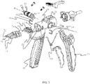
- FIGS 1-6 illustrate embodiments of aspects of the present invention. Reference signs to the elements described below are labeled on the embodiments in the Figures to assist in understanding the invention.
- the dispensing device ( 10 ) comprises a dispenser housing ( 20 ) within which is a spool valve ( 30 ).
- the spool valve controls flow of pressurized fluid through the dispensing device by rotation of a spool between an "open” configuration and a “closed” configuration.
- a spool valve comprises a spool ( 40 ) situated within a spool housing ( 24 ) that is defined by the dispenser housing.
- the spool housing is defined by a spool wall ( 50 ) around the spool housing within which the spool resides.
- the spool is typically generally cylindrical in shape with opposing ends ( 44 ) separated by a straight line axis ( A ).
- the spool can alternatively be generally spherical in shape with the straight line axis ( A ) extending through a diameter of the sphere.
- the spool resides in the spool housing with the straight line axis of the spool extending across the housing so that the spool can rotate around the straight line axis within the spool housing.
- the spool defines one or more than one channel ( 42 ) extending through the spool, through one point on the curved surface of the spool to another point on the surface of the spool. Generally, there is at least one such channel extending through the spool for each fluid that that is fed through the dispensing device.
- the spool wall has at least one entrance opening ( 52 ) and one exit opening ( 54 ) defined therethrough, preferably one entrance and one exit opening for each fluid that is fed through the dispensing device.
- the spool valve works by actuating the spool into an "open” configuration by rotating it along its straight line axis so as to align the entrance opening through a spool wall with an opening of a channel through the spool and an exit opening through the spool wall with the other opening of the channel through the spool thereby simultaneously providing fluid communication through the entrance opening in the wall, through the spool and through the exit opening in the wall.
- the spool valve can also be rotated into a "closed” configuration where the entrance and exit openings through spool walls do not simultaneously align with a channel through the spool.
- the dispenser housing defines at least one entrance channel ( 22 ). Typically, there is an entrance channel for each pressurized fluid that is fed to the dispenser.
- the entrance channel extends from the spool wall through the dispenser housing to outside of the dispenser housing.
- the portion of spool wall within a dispensing channel includes an entrance opening defined through that portion of spool wall.
- a force applying element ( 60 ) resides within the entrance channel, preferably within each entrance channel to which pressurized fluid is to be supplied.
- the force applying element is generally cylindrical in shape having opposing entrance ( 62 ) and exit ( 64 ) ends separated by a length. The exit end of the force applying element applies a force against at least a portion of the spool wall within the entrance channel in which the force applying element resides.
- the force applying element distinguishes the present dispensing device from other similar dispensing devices.
- the force applying element of the present invention is free of a straight line path of fluid communication through it. Instead the force applying element defines a tortuous flow path through which fluid must travel to go through the force applying element from entrance end through the exit end.
- a desirable form of the force applying element allows fluid flow to enter the force applying element through the entrance end generally parallel to the primary axis (length) of the force applying element and then forces fluid flow generally radially from the primary axis (generally perpendicular to the length) and around a barrier before again having to flow generally along the primary axis through the exit end of the force applying element.
- the force applying element of US944259 provides a straight line flow path through the force applying element.
- the fluid flow is directed through openings of a size that will preclude passage of solid particulates having a larger size than the openings in the force applying element flow path.
- the force applying element will serve as a filter for particulates having a larger size than the openings in the tortuous flow path through the force applying element.
- the force applying element has multiple such openings along the tortuous flow path to avoid immediate blockage of flow through the force applying element upon trapping a single particle. It is desirable for there to be a volume of space in which particles can collect when prevented from flowing through a particular opening in the force applying element much like a basket where particles can collect.
- Such a feature is achievable by designing the force applying element with a hollow core having multiple openings out from the hollow core through which fluid can flow but particulates larger than the openings cannot. The particulates then can collect in the hollow core, which acts as a basket.
- the force applying element can comprise an entrance end plate ( 66 ) and an exit end plate ( 68 ) each having a diameter ( D ) that is larger than the diameter of the rest of the force applying element.
- the entrance end plate and exit end plate each have a hole extending all the way through them in the thickness dimension, extending through opposing primary surfaces.
- a porous basket element ( 600 ) which can act as a basket to collect trapped particulates, is desirably attached to both the entrance end plate and exit end plate and extends between the entrance end plate and exit end plate, with the porous basket element spaced apart from the exit end plate.
- the force applying element can comprise a barrier ( 700 ) that prevents linear flow through the entrance end plate through the porous basket element and through the exit end plate but rather forces generally radial flow out from the porous basket element and around the barrier to reach the hole through the exit end plate to exit the force applying element.
- FIG. 1-5 A force applying element having a sequence of plates design is illustrated in Figures 1-5 .
- the force applying element having a sequence of plates design comprises a porous basket element comprising a sequence of plates ( 65 ) each defining a hole through their thickness and spaced apart by a plate spacing ( d ) and connected to one another by spacers ( 69 ) with their primary surfaces facing one another and aligned sequentially from the entrance end plate to the exit end plate of the force applying element with fluid communication between the plates through the holes they define and radially between the plates.
- the plates can have any desirable cross sectional shape including circular cross section, elliptical cross, triangular cross section, star-shaped cross section, square cross section and rectangular cross section.
- the plates can have flat primary surfaces or can have concave, convex or any other contour for the primary surface.
- the spacers attaching the plates leave space for fluid communication from the hole through plates radially out around the edge of the plates.
- the spacers attach to primary surfaces of adjacent plates.
- spacers are staggered in alignment along the sequence of plates so that any one plate is free of spacers directly opposite one another on opposing sides of the plate.
- one desirable configuration is to include three spacers between plates with spacers at 12, 4 and 8 O'clock position on one primary surface of a plate and 2, 6 and 10 O'clock positions on the opposing primary surface of the plate. Spacers in a staggered configuration allow for the plates to flext slightly when under force thereby making the force applying element capable of absorbing excess force applied through the force applying element.
- Both the entrance end plate and the exit end plate define a hole all the way through each plate extending through opposing primary surfaces of each plate (that is, through the thickness of the plate).
- the entrance end plate and exit end plate have a larger diameter ( D ) than the majority of, preferably all of, the plates in between the entrance end plate and exit end plate.
- the entrance end plate and exit end plate have a cross section that conforms to the size and shape of the cross section of the entrance channel in which the force applying element resides so that the force applying element can be inserted into the entrance channel but has minimal space between the edges of the entrance and exit end plate edges and the dispenser housing around the entrance channel.
- a plate proximate to, preferably adjacent to, the exit end plate is a solid plate ( 67 ) (that is, a plate free of a hole extending through the thickness of the plate) and serves as a barrier ( 700 ) component for the force applying element.
- the majority of, preferably all of, the other plates in the force applying element define a hole extending through the thickness of the plate.
- the space between the plates making up the basket serve as openings in the basket through which fluid can flow radially out from the basket, around the solid plate and radially back between the solid plate and exit end plate and then through the hole in the exit end plate to exit the force applying device.
- the holes through the plates are larger than the plate spacings. Therefore, particulates will get trapped in the basket if they are larger than the plate spacing of the plates defining the basket.
- the force applying element of the sequential plate design forces a tortuous fluid flow through it by having fluid enter through the opening in the entrance end plate and travel through the "basket” formed by subsequent plates having a hole therethrough and then forcing radial flow out from the "basket” through plate spacing holes to go around a solid plate and then flow generally radially back into the force applying element to exit the force applying element through the hole in the exit end plate.
- the hole in the exit plate is in fluid communication with the entrance hole in the spool wall so fluid flow proceeds from the force applying element through the entrance hole in the spool wall.
- the force applying element having a sequential plate design can define multiple "baskets" by including one or more additional solid plate into the sequence of plates and separating the solid plates from one another with plates having a hole through their thickness.
- FIG. 6(a)-6(c) Another suitable design of a force applying element having a hollow core with openings out from the hollow core is referred to herein as a "porous cylinder" design.
- the basket design is generally illustrated in Figures 6(a)-6(c) .
- the porous cylinder design is similar to the sequential plate and includes an entrance end plate ( 66 ) and exit end plate ( 68 ) as described above.
- the entrance end plate and exit end plate define a hole through their thickness as in the sequential plate design.
- the force applying element instead of sequential plates with spacings between them serving as the porous basket element, has a tubular or cylindrical core ( 200 ) with a core wall ( 210 ) extending from the entrance end plate towards the exit end plate that defines within it a hollow center space ( 220 ) which serves as the porous basket element ( 600 ).
- the core wall provides fluid communication from the hollow center space to outside the cylindrical core.
- the solid end is attached to the exit end plate with spacers ( 69 ) as described above that set the solid end spaced apart from exit end plate and from one another so as to allow fluid communication from outside the cylindrical core to the hole through the exit end plate.
- a tortuous fluid flow path is required to flow through the porous cylinder design force applying element as fluid enters the force applying element through the hole in the entrance end plate into the hollow center of the core, then radially out through the holes in the core wall around the solid bottom and radially back to the hole through the exit end plate.
- the size of the holes in the core wall limit the size of particulate than can flow through the force applying element.
- the hollow core serves as a basket to hold trapped particulates in the force applying element.
- the sequential plate design and porous cylinder designs are very similar and can actually be visualized as alternative forms of one another.
- the sequential plate design is essentially a porous cylinder design with slots for holes through the core wall.
- the porous cylinder design can be visualized as a sequential plate design with sufficiently sized spacers to fill the plate spacings so as to only leave holes between them.
- an entrance end plate and an exit end plate each having a larger diameter than the rest of the force applying element and having a hole extending all the way through their thickness;
- a porous basket element attached to and extending between the entrance end plate and exit end plate; and
- a barrier that prevents linear flow through the entrance end plate through the basket and through the exit end plate but rather forces generally radial flow out from the porous basket and around the barrier to reach the exit end plate.
- At least one, and preferably each, entrance opening through the spool wall against which a force applying element applies force has defined therearound a nib ( 56 ) extending into the entrance channel from the spool wall that is in contact with the force applying element.
- the exit end plate the force applying element has a hole defined therethrough into which the nib inserts and seals.
- the plate spacing in the sequential plate design and the holes in the porous cylinder design are 0.8 millimeters or less and at the same time 0.1 millimeters or more so as to trap particulates having a size greater than 0.8 millimeters.
- the dispensing device further comprises a hose adapter fitting (7 0 ) that has opposing entrance ( 72 ) and exit ( 74 ) ends.
- the entrance end extends out from the dispenser housing and the exit end extends into the entrance channel and contacts the force applying element.
- the force applying element and the dispensing device can be a single piece or can be separate pieces. It is desirable for ease of fabrication for the hose adapter fitting and the force applying element to be separate pieces.
- the hose adapter fitting desirably presses against the force applying element so as to press the force applying element against the spool wall.
- the hose adapter fitting defines a flow passage ( 76 ) all the way through it, through the entrance end and exit ends. As such, there is fluid communication all the way through the flow passage of the hose adapter fitting into and through the force applying element and into an entrance opening of the spool wall.
- the force applying element can press against the spool wall with sufficient force so as to deflect the spool wall against the spool so as to form a fluid-tight seal around the entrance hole proximate to the force applying element and the spool when the spool wall is deflected.
- the hose adapter fitting can press the force applying element against the spool wall with sufficient force to deflect the spool wall.
- the hose adapter fitting is typically held in place with a snap or clip to maintain the force.
- a metal clip ( 78 ) can extend through the dispenser housing and into or around the hose adapter fitting.
- the hose adapter fitting can have one or more protrusion (such as a ring around its perimeter) that snaps into a groove of the dispenser housing within the entrance channel.
- the fluid dispensing device can, and desirably does, have multiple entrance channels into which a force applying element as described above and hose adapter fitting reside.
- the fluid dispensing device comprises multiple entrance channels with force applying elements and hose adapter fittings the entrance channels desirably feed to a single spool valve having a single spool with multiple channels extending through it.
- a different channel desirably lines up in fluid communication with each entrance channel (that is, the fluid path through the hose adapter fitting and force applying element within the entrance channel).
- the spool is in a "closed” configuration, it is desirable for channels through the spool to no longer align in fluid communication with the entrance channels containing a force applying element and hose adapter fitting.
- the fluid dispensing device can have two entrance channels each containing a force applying element and a hose adapter fitting.
- Such a device is useful for dispensing two-component polyurethane foam compositions by feeding an A-component of the composition through the hose adapter fitting and force applying element in one entrance channel and a B-component of the composition through the hose adapter fitting and force applying element in the other entrance channel.
- the fluid dispensing device desirably is trigger actuated.
- the fluid dispensing device to comprise a trigger ( 80 ) attached to the spool such that when the trigger is moved in one way the spool rotates into an "open" configuration and when the trigger is moved in a different way the spool rotates into a "closed” configuration.
- a trigger can attach to one or both ends of the spool through the dispenser housing either by having the trigger having extension that go through holes in the dispenser housing or by having the spool extend out from the dispenser housing.
- the spool can, for example, have a tab ( 46 ) on one or both end along straight line axis A to which the trigger attaches.
- the fluid dispensing device can comprise a handle ( 90 ), preferably a handle that is attached and remains stationary with respect to the dispenser housing.
- a handle provides a means by which a user can hold the dispensing device.
- a handle also provides a means against which a trigger can be pulled.
- the dispensing device can desirably comprise a trigger and a handle as described in addition to a spring device ( 100 ) that holds the trigger apart from the handle. Displacing the trigger towards the handle can actuate the spool by rotating it into an "open” orientation. Releasing pressure on the trigger and allowing the spring to displace the trigger away from the handle can actuate the spool and rotate it to a "closed” orientation.
- Such a spring element can reside between the handle and trigger so that it compresses when the trigger is pulled towards the handle and expands when the trigger moves away from the handle.
- Suitable examples of such springs, handles and triggers and their configurations suitable for use in the present invention are taught in US5944259 and US2017/0157624 .
- the dispenser of US5944259 can be modified so as to replace the force applying element taught therein with the force applying element as taught herein.
Landscapes
- Engineering & Computer Science (AREA)
- Mechanical Engineering (AREA)
- Nozzles (AREA)
- Coating Apparatus (AREA)
- Valve Housings (AREA)
- Details Of Valves (AREA)
- Feeding, Discharge, Calcimining, Fusing, And Gas-Generation Devices (AREA)
- Loading And Unloading Of Fuel Tanks Or Ships (AREA)
Description
- The present invention relates to a fluid dispensing device that filters particulates from the incoming fluid.
- Dispensing devices such as spray guns are useful for dispensing pressurized fluids. Dispensing devices for dispensing reactive two-component fluids are particularly challenging in design because the reactive fluids must be kept separate until such time as they are dispensed and then they must be mixed and dispensed rapidly and the device must preclude leaking of the reactive components. One such reactive two-component system that utilizes a dispensing device is a two-part polyurethane foam formulation. Dispensing devices for two-part polyurethane foam formulations typically have two fluid inlets and an exit with a spray nozzle. Two chemical feeds, typically described as the A-side (isocyanate containing fluid) and B-Side (polyol containing side) feed into the dispensing device through separate fluid inlets and then are mixed just prior to expelling from the spray nozzle. The dispensing device typically has a triggered valve that starts and stops flow of the A-side and B-side feeds through the dispensing device when actuated.
- One popular dispensing device for two-part polyurethane foam formulations is described in
US5944259 ('259). The dispensing device of '259 is a spray gun with a spool valve. The A-side and B-side fluids feed into the spray gun through separate entrance channels to the spool valve. The entrance channels comprise a hose adapter fitting and a force applying element between the hose adapter fitting and a wall around the spool of the spool valve. The hose adapter fitting applies force through the force applying element so as to press the spool valve wall against the spool of the spool valve to prevent leaking of fluid around the spool. When the trigger is actuated to turn the spool into an "open" configuration fluid is able to flow through the hose adapter fittings, through the force applying elements, through entrance holes in the spool wall and through the spool of the spool valve to reach a mixing nozzle through which the two fluids are mixed just prior to exiting the spray gun. - The present inventors have discovered a challenge with dispensing devices such as that described in
US5944259 and further have discovered how to resolve those challenges with the present invention. Another known dispensing device is shown inDE4232439A1 andDE 2055936A1 . - The present inventors have discovered a challenge with dispensing devices, particularly with those of two-part polyurethane foam formulations. When particulates are present in one or more fluid flowing through the spool valve there tends to be a problem of the dispensing device plugging. The inventors have discovered that the A-side component of a two-part polyurethane formulation can develop crystals when stored at temperatures of 4.4 degrees Celsius (°C), 40 degrees Fahrenheit, or colder. Contaminant particulates such as crystals can plug the spray gun, causing inconsistent flow and/or inconsistent blend ratios of the A-part and B-part components. Therefore, it is desirable to solve this problem of plugging and/or blockage of the flow of fluid through the spray gun due to particulate contaminants.
- Moreover, it is desirable to solve this problem without having to add any additional elements to the dispensing device.
- The present inventors have found a solution to the problem by modifying the force applying element in a dispensing device utilizing a spool valve similar to that described in '259. Notably, the solution is applicable to dispensing devices having one feed channel or multiple feed channels (such as that in '529) so it has applicability beyond the precise dispensing device described in'259. Nonetheless, it is particularly useful in a dispensing device such as that described in '259.
- The solution provided in the present invention is a result of redesigning the force applying element so as to have a tortuous path through which fluid must flow as opposed to a straight line flow path through the force applying element. The tortuous path is achieved by blocking fluid flow directly through the force applying element and forcing fluid flow to move radially out from the force applying element and then back in radially in order to pass through the force applying element. Filtering is achieved by creating flow-path spacing along the tortuous path that are only large enough to pass fluid and solid particulates smaller than the spacing along the tortuous path. Particulates having a larger size than the flow-path spacing become trapped in the force applying element rather than traveling further into the dispenser to plug the device downstream. Desirably, the force applying element has a volume within it to collect trapped particulates without immediately plugging the dispensing device.
- In a first aspect, the present invention is a fluid dispensing device according to claim 1.
- The present invention is useful for dispensing fluids such as two-part polyurethane foam formulations.
-
-
Figure 1 is an angled side view of a dispensing device of the present invention. -
Figure 2 is an exploded view of the dispensing device ofFigure 1 . -
Figure 3 is a cut-away side view of a dispensing device of the present invention cut through a flow passage of a hose adapter. -
Figure 4 is another cut-away side view of a dispensing device of the present invention cut through a flow passage of a hose adapter. -
Figures 5(a)-5(c) provide angled view, side view and cut-away side view respectively of a force applying element having a "sequence of plates" design. -
Figure 6(a)-6(c) provide angled view, side view and cut-away side view respectively of a force applying element having a "porous cylinder" design. - All publications mentioned herein are incorporated herein by reference to disclose and describe the methods and/or materials in connection with which the publications are cited.
- It is to be understood that the terminology used herein is for the purpose of describing particular aspects only and is not intended to be limiting. Unless defined otherwise, all technical and scientific terms used herein have the same meaning as commonly understood by one of ordinary skill in the art to which this invention belongs. In this specification and in the claims which follow, reference will be made to a number of terms which are defined herein.
- "And/or" means "and, or as an alternative". All ranges include endpoints unless otherwise indicated. "Multiple" means two or more.
- "Primary surface" refers to the surface of an object that has a planar surface area equal to the largest planar surface area of any surface of the object. A planar surface area refers to the surface area of a surface as projected onto a plane so as to eliminate consideration of surface contours and features such as peaks and valleys in the surface area calculation. Plates, discs and boards have opposing primary surfaces separated by a thickness dimension. "Edges" of a plate, disc or board refer to the surface or surfaces extending around the circumference of the primary faces and along the thickness of the object.
- "Diameter" refers to the largest cross sectional dimension of an object and does not imply the object necessarily has a circular cross section.
- The present invention can be understood more readily by reference to the following detailed description, examples, drawings, and claims, and their previous and following description.
- While the present invention is capable of being embodied in various forms, the description below of several embodiments is made with the understanding that the present disclosure is to be considered as an exemplification of the invention, and is not intended to limit the invention to the specific embodiments illustrated. Headings are provided for convenience only and are not to be construed to limit the invention in any manner.
- The present invention is a dispensing device useful for dispensing pressurized fluid. Desirably, the dispensing device of the present invention is useful for simultaneously dispensing multiple pressurized fluids. In that regard, the present invention provides a device into which one or more than one pressurized fluid is provided and out from which one or more than one fluid is dispensed. A particularly desirable embodiment of the present invention accommodates independently feeding the A-part and B-part of a two part polyurethane foam formulation into the dispensing device of the present invention and then mixing and dispensing of the A-part and B-part to produce a polyurethane foam.
-
Figures 1-6 illustrate embodiments of aspects of the present invention. Reference signs to the elements described below are labeled on the embodiments in the Figures to assist in understanding the invention. - The dispensing device (10) comprises a dispenser housing (20) within which is a spool valve (30). The spool valve controls flow of pressurized fluid through the dispensing device by rotation of a spool between an "open" configuration and a "closed" configuration.
- A spool valve comprises a spool (40) situated within a spool housing (24) that is defined by the dispenser housing. The spool housing is defined by a spool wall (50) around the spool housing within which the spool resides. The spool is typically generally cylindrical in shape with opposing ends (44) separated by a straight line axis (A). The spool can alternatively be generally spherical in shape with the straight line axis (A) extending through a diameter of the sphere. The spool resides in the spool housing with the straight line axis of the spool extending across the housing so that the spool can rotate around the straight line axis within the spool housing. The spool defines one or more than one channel (42) extending through the spool, through one point on the curved surface of the spool to another point on the surface of the spool. Generally, there is at least one such channel extending through the spool for each fluid that that is fed through the dispensing device. The spool wall has at least one entrance opening (52) and one exit opening (54) defined therethrough, preferably one entrance and one exit opening for each fluid that is fed through the dispensing device. The spool valve works by actuating the spool into an "open" configuration by rotating it along its straight line axis so as to align the entrance opening through a spool wall with an opening of a channel through the spool and an exit opening through the spool wall with the other opening of the channel through the spool thereby simultaneously providing fluid communication through the entrance opening in the wall, through the spool and through the exit opening in the wall. The spool valve can also be rotated into a "closed" configuration where the entrance and exit openings through spool walls do not simultaneously align with a channel through the spool.
- The dispenser housing defines at least one entrance channel (22). Typically, there is an entrance channel for each pressurized fluid that is fed to the dispenser. The entrance channel extends from the spool wall through the dispenser housing to outside of the dispenser housing. The portion of spool wall within a dispensing channel includes an entrance opening defined through that portion of spool wall.
- A force applying element (60) resides within the entrance channel, preferably within each entrance channel to which pressurized fluid is to be supplied. The force applying element is generally cylindrical in shape having opposing entrance (62) and exit (64) ends separated by a length. The exit end of the force applying element applies a force against at least a portion of the spool wall within the entrance channel in which the force applying element resides.
- The force applying element distinguishes the present dispensing device from other similar dispensing devices. The force applying element of the present invention is free of a straight line path of fluid communication through it. Instead the force applying element defines a tortuous flow path through which fluid must travel to go through the force applying element from entrance end through the exit end. For example, a desirable form of the force applying element allows fluid flow to enter the force applying element through the entrance end generally parallel to the primary axis (length) of the force applying element and then forces fluid flow generally radially from the primary axis (generally perpendicular to the length) and around a barrier before again having to flow generally along the primary axis through the exit end of the force applying element. In contrast, the force applying element of
US944259 provides a straight line flow path through the force applying element. - In directing the path of fluid flow in a tortuous flow path through the force applying element, the fluid flow is directed through openings of a size that will preclude passage of solid particulates having a larger size than the openings in the force applying element flow path. Hence, the force applying element will serve as a filter for particulates having a larger size than the openings in the tortuous flow path through the force applying element. Desirably, the force applying element has multiple such openings along the tortuous flow path to avoid immediate blockage of flow through the force applying element upon trapping a single particle. It is desirable for there to be a volume of space in which particles can collect when prevented from flowing through a particular opening in the force applying element much like a basket where particles can collect. Such a feature is achievable by designing the force applying element with a hollow core having multiple openings out from the hollow core through which fluid can flow but particulates larger than the openings cannot. The particulates then can collect in the hollow core, which acts as a basket.
- The force applying element can comprise an entrance end plate (66) and an exit end plate (68) each having a diameter (D) that is larger than the diameter of the rest of the force applying element. The entrance end plate and exit end plate each have a hole extending all the way through them in the thickness dimension, extending through opposing primary surfaces. A porous basket element (600) which can act as a basket to collect trapped particulates, is desirably attached to both the entrance end plate and exit end plate and extends between the entrance end plate and exit end plate, with the porous basket element spaced apart from the exit end plate. The force applying element can comprise a barrier (700) that prevents linear flow through the entrance end plate through the porous basket element and through the exit end plate but rather forces generally radial flow out from the porous basket element and around the barrier to reach the hole through the exit end plate to exit the force applying element.
- One suitable design of a force applying element having a hollow core with openings out from the hollow core is referred to herein as a "sequence of plates" design. A force applying element having a sequence of plates design is illustrated in
Figures 1-5 . - The force applying element having a sequence of plates design comprises a porous basket element comprising a sequence of plates (65) each defining a hole through their thickness and spaced apart by a plate spacing (d) and connected to one another by spacers (69) with their primary surfaces facing one another and aligned sequentially from the entrance end plate to the exit end plate of the force applying element with fluid communication between the plates through the holes they define and radially between the plates. The plates can have any desirable cross sectional shape including circular cross section, elliptical cross, triangular cross section, star-shaped cross section, square cross section and rectangular cross section. The plates can have flat primary surfaces or can have concave, convex or any other contour for the primary surface. The spacers attaching the plates leave space for fluid communication from the hole through plates radially out around the edge of the plates.
- Desirably, the spacers attach to primary surfaces of adjacent plates. Preferably, spacers are staggered in alignment along the sequence of plates so that any one plate is free of spacers directly opposite one another on opposing sides of the plate. For example, one desirable configuration is to include three spacers between plates with spacers at 12, 4 and 8 O'clock position on one primary surface of a plate and 2, 6 and 10 O'clock positions on the opposing primary surface of the plate. Spacers in a staggered configuration allow for the plates to flext slightly when under force thereby making the force applying element capable of absorbing excess force applied through the force applying element.
- Both the entrance end plate and the exit end plate define a hole all the way through each plate extending through opposing primary surfaces of each plate (that is, through the thickness of the plate). The entrance end plate and exit end plate have a larger diameter (D) than the majority of, preferably all of, the plates in between the entrance end plate and exit end plate. Desirably, the entrance end plate and exit end plate have a cross section that conforms to the size and shape of the cross section of the entrance channel in which the force applying element resides so that the force applying element can be inserted into the entrance channel but has minimal space between the edges of the entrance and exit end plate edges and the dispenser housing around the entrance channel.
- A plate proximate to, preferably adjacent to, the exit end plate is a solid plate (67) (that is, a plate free of a hole extending through the thickness of the plate) and serves as a barrier (700) component for the force applying element. The majority of, preferably all of, the other plates in the force applying element define a hole extending through the thickness of the plate. As a result, the sequence of plates making up the force applying element essentially forms a basket with the solid plate serving as the bottom of the basket and the entrance end plate serving as the top of the basket with a brim broader than the diameter of the basket. The space between the plates making up the basket serve as openings in the basket through which fluid can flow radially out from the basket, around the solid plate and radially back between the solid plate and exit end plate and then through the hole in the exit end plate to exit the force applying device. The holes through the plates are larger than the plate spacings. Therefore, particulates will get trapped in the basket if they are larger than the plate spacing of the plates defining the basket. The force applying element of the sequential plate design forces a tortuous fluid flow through it by having fluid enter through the opening in the entrance end plate and travel through the "basket" formed by subsequent plates having a hole therethrough and then forcing radial flow out from the "basket" through plate spacing holes to go around a solid plate and then flow generally radially back into the force applying element to exit the force applying element through the hole in the exit end plate. The hole in the exit plate is in fluid communication with the entrance hole in the spool wall so fluid flow proceeds from the force applying element through the entrance hole in the spool wall.
- The force applying element having a sequential plate design can define multiple "baskets" by including one or more additional solid plate into the sequence of plates and separating the solid plates from one another with plates having a hole through their thickness.
- Another suitable design of a force applying element having a hollow core with openings out from the hollow core is referred to herein as a "porous cylinder" design. The basket design is generally illustrated in
Figures 6(a)-6(c) . - The porous cylinder design is similar to the sequential plate and includes an entrance end plate (66) and exit end plate (68) as described above. The entrance end plate and exit end plate define a hole through their thickness as in the sequential plate design. However, instead of sequential plates with spacings between them serving as the porous basket element, the force applying element has a tubular or cylindrical core (200) with a core wall (210) extending from the entrance end plate towards the exit end plate that defines within it a hollow center space (220) which serves as the porous basket element (600). There is a solid end (230) opposite the entrance end plate on the cylindrical core that serves as the barrier (700). There are multiple holes (240) extending through the core wall providing fluid communication from the hollow center space to outside the cylindrical core. The solid end is attached to the exit end plate with spacers (69) as described above that set the solid end spaced apart from exit end plate and from one another so as to allow fluid communication from outside the cylindrical core to the hole through the exit end plate. A tortuous fluid flow path is required to flow through the porous cylinder design force applying element as fluid enters the force applying element through the hole in the entrance end plate into the hollow center of the core, then radially out through the holes in the core wall around the solid bottom and radially back to the hole through the exit end plate. The size of the holes in the core wall limit the size of particulate than can flow through the force applying element. The hollow core serves as a basket to hold trapped particulates in the force applying element.
- The sequential plate design and porous cylinder designs are very similar and can actually be visualized as alternative forms of one another. The sequential plate design is essentially a porous cylinder design with slots for holes through the core wall. Alternatively, the porous cylinder design can be visualized as a sequential plate design with sufficiently sized spacers to fill the plate spacings so as to only leave holes between them. Similar to both designs is: (a) an entrance end plate and an exit end plate each having a larger diameter than the rest of the force applying element and having a hole extending all the way through their thickness; (b) a porous basket element attached to and extending between the entrance end plate and exit end plate; and (c) a barrier that prevents linear flow through the entrance end plate through the basket and through the exit end plate but rather forces generally radial flow out from the porous basket and around the barrier to reach the exit end plate.
- Desirably, at least one, and preferably each, entrance opening through the spool wall against which a force applying element applies force has defined therearound a nib (56) extending into the entrance channel from the spool wall that is in contact with the force applying element. Preferably, the exit end plate the force applying element has a hole defined therethrough into which the nib inserts and seals. Such a configuration provides a secure engagement between the spool wall and force applying element that requires flow out from the exit end of the force applying element to flow into the entrance opening through the spool wall.
- Desirably, the plate spacing in the sequential plate design and the holes in the porous cylinder design are 0.8 millimeters or less and at the same time 0.1 millimeters or more so as to trap particulates having a size greater than 0.8 millimeters.
- The dispensing device further comprises a hose adapter fitting (70) that has opposing entrance (72) and exit (74) ends. The entrance end extends out from the dispenser housing and the exit end extends into the entrance channel and contacts the force applying element. The force applying element and the dispensing device can be a single piece or can be separate pieces. It is desirable for ease of fabrication for the hose adapter fitting and the force applying element to be separate pieces. When separate pieces, the hose adapter fitting desirably presses against the force applying element so as to press the force applying element against the spool wall. The hose adapter fitting defines a flow passage (76) all the way through it, through the entrance end and exit ends. As such, there is fluid communication all the way through the flow passage of the hose adapter fitting into and through the force applying element and into an entrance opening of the spool wall.
- It is desirable for the force applying element to press against the spool wall with sufficient force so as to deflect the spool wall against the spool so as to form a fluid-tight seal around the entrance hole proximate to the force applying element and the spool when the spool wall is deflected. The hose adapter fitting can press the force applying element against the spool wall with sufficient force to deflect the spool wall. The hose adapter fitting is typically held in place with a snap or clip to maintain the force. For instance, a metal clip (78) can extend through the dispenser housing and into or around the hose adapter fitting. Additionally, the hose adapter fitting can have one or more protrusion (such as a ring around its perimeter) that snaps into a groove of the dispenser housing within the entrance channel.
- The fluid dispensing device can, and desirably does, have multiple entrance channels into which a force applying element as described above and hose adapter fitting reside. When the fluid dispensing device comprises multiple entrance channels with force applying elements and hose adapter fittings the entrance channels desirably feed to a single spool valve having a single spool with multiple channels extending through it. When the spool is in an "open" configuration a different channel desirably lines up in fluid communication with each entrance channel (that is, the fluid path through the hose adapter fitting and force applying element within the entrance channel). When the spool is in a "closed" configuration, it is desirable for channels through the spool to no longer align in fluid communication with the entrance channels containing a force applying element and hose adapter fitting. For example, the fluid dispensing device can have two entrance channels each containing a force applying element and a hose adapter fitting. Such a device is useful for dispensing two-component polyurethane foam compositions by feeding an A-component of the composition through the hose adapter fitting and force applying element in one entrance channel and a B-component of the composition through the hose adapter fitting and force applying element in the other entrance channel.
- The fluid dispensing device desirably is trigger actuated. In that regard, it is desirable for the fluid dispensing device to comprise a trigger (80) attached to the spool such that when the trigger is moved in one way the spool rotates into an "open" configuration and when the trigger is moved in a different way the spool rotates into a "closed" configuration. For example, a trigger can attach to one or both ends of the spool through the dispenser housing either by having the trigger having extension that go through holes in the dispenser housing or by having the spool extend out from the dispenser housing. The spool can, for example, have a tab (46) on one or both end along straight line axis A to which the trigger attaches.
- Additionally, it is further desirable for the fluid dispensing device to comprise a handle (90), preferably a handle that is attached and remains stationary with respect to the dispenser housing. Such a handle provides a means by which a user can hold the dispensing device. A handle also provides a means against which a trigger can be pulled. The dispensing device can desirably comprise a trigger and a handle as described in addition to a spring device (100) that holds the trigger apart from the handle. Displacing the trigger towards the handle can actuate the spool by rotating it into an "open" orientation. Releasing pressure on the trigger and allowing the spring to displace the trigger away from the handle can actuate the spool and rotate it to a "closed" orientation. Such a spring element can reside between the handle and trigger so that it compresses when the trigger is pulled towards the handle and expands when the trigger moves away from the handle. Suitable examples of such springs, handles and triggers and their configurations suitable for use in the present invention are taught in
US5944259 andUS2017/0157624 . - As an example of a dispenser of the present invention, the dispenser of
US5944259 can be modified so as to replace the force applying element taught therein with the force applying element as taught herein.
Claims (8)
- A fluid dispensing device (10) comprising:(a) a spool valve (30) within a dispenser housing (20), the spool valve comprising a spool (40) within a spool housing (24), the spool housing comprising a spool wall (50) around the spool housing with at least one entrance opening (52) and at least one exit opening (54) defined through the spool wall;(b) an entrance channel (22) in the dispenser housing proximate to the entrance opening in the spool wall;(c) a force applying element (60) within the entrance channel, where the force applying element applies force against the spool wall around the entrance opening, the force applying element being generally cylindrical with opposing entrance (62) and exit (64) ends with the exit end most proximate to the spool wall; and(d) a hose adapter fitting (70) that has opposing entrance (72) and exit (74) ends, where the entrance end extends out from the dispenser housing and the exit end extends into the entrance channel and is in contact with the force applying element, wherein the hose adapter fitting defines a flow passage (76) extending through it from entrance end to exit end; andwherein there is fluid communication all the way through the flow passage of the hose adapter fitting into and through the force applying element and into an entrance opening in the spool wall; and wherein the force applying element defines a tortuous flow path through which fluid must travel to go through the force applying element from entrance end through exit end;characterized in that the hose adapter fitting applies force to the spool wall through the force applying element such that the spool wall deflects against the spool when the force is applied,or at least one entrance opening through the spool wall has a nib (56) around it that protrudes towards and contacts the force applying element and against which the force applying element applies force to the spool wall.
- The fluid dispensing device of Claim 1, wherein the force applying element is a separate piece from the hose adapter fitting.
- The fluid dispensing device of Claim 1, the device having two or more entrance openings through the spool wall, and separate entrance channels in the dispenser housing opening to one of the entrance openings in the spool wall and each entrance channel having a force applying element and a hose adapter fitting inserted therein.
- The fluid dispensing device of any one previous claim, wherein the force applying element comprises an entrance end plate (66) and an exit end plate (68) each having a larger diameter (D) than the rest of the force applying element and having a hole extending all the way through their thickness, a porous basket element (600) attached to and extending between the entrance end plate and exit end plate with the porous basket element spaced apart from the exit end plate, and a barrier (700) that prevents linear flow through the entrance end plate through the porous basket element and through the exit end plate but rather forces generally radial flow out from the porous basket element and around the barrier to reach the hole through the exit end plate.
- The fluid dispensing device of Claim 4, wherein the force applying element is characterized by a design selected from a group consisting of the following two designs:a. a sequence of plates design where the porous basket element is a sequence of plates (65) defining a hole through their thickness, the plates having primary surfaces and spaced apart by a plate spacing (d) and connected to one another by spacers (69) with the primary surfaces of the plates facing one another and aligned sequentially from the entrance end plate to the exit end plate with fluid communication between the plates through the holes they define and radially between the plates, and where the barrier is a solid plate proximate to the exit end plate; andb. a porous cylinder design where the porous basket element is a cylindrical core (200) extending between and attaching to the entrance plate and exit end plate, where the cylindrical core has a core wall (210) defining a hollow center space within the cylindrical core and having holes (240) defined therethrough and a solid end (230) opposite the entrance end plate, where the cylindrical core extends off from the entrance end plate with the core walls around the hole defined through the entrance plate so that there is fluid communication through the entrance end plate into the hollow center of the core and with the solid end attached to the exit end plate with spacers (69) that set the solid end spaced apart from the exit end plate; wherein there is fluid communication through the hole in the entrance end plate into the hollow core and out through the holes in the core wall around the solid end and spacers and through the hole in the exit end plate.
- The fluid dispensing device of Claim 5, wherein when the force applying element has a sequence of plates design the plate spacing between any two plates of the force applying element being 0.8 millimeters or less and at the same time 0.1 millimeters or more as measured between adjacent primary surfaces and when the force applying element has a porous cylinder design the holes have a diameter of 0.8 millimeter or less and at the same time 0.1 millimeters or more.
- The fluid dispensing device of Claim 5, wherein the force applying element is a sequence of plates design with one solid plate adjacent to the exit end plate.
- The fluid dispensing device of Claim 6, wherein the force applying element is a sequence of plates design with one solid plate adjacent to the exit end plate.
Applications Claiming Priority (2)
| Application Number | Priority Date | Filing Date | Title |
|---|---|---|---|
| US201762585615P | 2017-11-14 | 2017-11-14 | |
| PCT/US2018/061016 WO2019099492A1 (en) | 2017-11-14 | 2018-11-14 | Filtering fluid dispensing device |
Publications (3)
| Publication Number | Publication Date |
|---|---|
| EP3710168A1 EP3710168A1 (en) | 2020-09-23 |
| EP3710168B1 true EP3710168B1 (en) | 2022-11-09 |
| EP3710168B8 EP3710168B8 (en) | 2022-12-14 |
Family
ID=64572558
Family Applications (1)
| Application Number | Title | Priority Date | Filing Date |
|---|---|---|---|
| EP18812528.0A Active EP3710168B8 (en) | 2017-11-14 | 2018-11-14 | Filtering fluid dispensing device |
Country Status (6)
| Country | Link |
|---|---|
| US (1) | US11813632B2 (en) |
| EP (1) | EP3710168B8 (en) |
| JP (1) | JP7257396B2 (en) |
| CN (1) | CN111741817B (en) |
| CA (1) | CA3081590A1 (en) |
| WO (1) | WO2019099492A1 (en) |
Families Citing this family (4)
| Publication number | Priority date | Publication date | Assignee | Title |
|---|---|---|---|---|
| EP3877095B1 (en) * | 2018-11-09 | 2025-02-26 | Illinois Tool Works Inc. | Modular fluid application device for varying fluid coat weight |
| MX2022004921A (en) * | 2019-10-23 | 2022-07-27 | Foam Supplies Inc | Metal foam dispenser and method of use for polyurethane foam dispensing. |
| EP4366885B1 (en) * | 2021-07-07 | 2025-12-10 | Carlisle Construction Materials, LLC | Applicator |
| CN116899773B (en) * | 2023-09-14 | 2023-11-14 | 济南京华邦威聚氨酯设备有限公司 | Polyurethane polyurea spray gun |
Family Cites Families (16)
| Publication number | Priority date | Publication date | Assignee | Title |
|---|---|---|---|---|
| US944259A (en) | 1909-02-23 | 1909-12-28 | William F Quigg | Insulator. |
| DE2055936A1 (en) * | 1970-11-13 | 1972-05-18 | Fa. Ing. Josef Wagner, 7991 Friedrichshafen-Fischbach | Handle for airless spray guns |
| US5333790A (en) * | 1992-04-20 | 1994-08-02 | Christopher Gilman O | Quick disconnect nozzle apparatus |
| DE4244902C2 (en) * | 1992-09-28 | 1998-03-12 | Wagner Gmbh J | Spray gun for airless paint etc. spraying |
| US5944259A (en) * | 1997-08-06 | 1999-08-31 | Flexible Products Company | Spray gun with improved seal |
| US6021961A (en) | 1998-03-06 | 2000-02-08 | Flexible Products Company | Crossover-resistant plural component mixing nozzle |
| US6186409B1 (en) | 1998-12-10 | 2001-02-13 | Bowles Fluidics Corporation | Nozzles with integrated or built-in filters and method |
| JP4545888B2 (en) * | 2000-06-08 | 2010-09-15 | 株式会社泉精器製作所 | Solid-liquid separator |
| US8608091B2 (en) * | 2005-03-18 | 2013-12-17 | 3M Innovative Properties Company | Dispensing gun assembly for mixing and dispensing plural component foam |
| ES2509517T3 (en) | 2010-09-14 | 2014-10-17 | J. Wagner Ag | Filter for spray guns for the filtering of liquids and their use |
| US20130240435A1 (en) * | 2012-03-16 | 2013-09-19 | Techtronic Power Tools Technology Limited | Universal filter |
| US10035155B2 (en) | 2014-09-15 | 2018-07-31 | Dow Global Technologies Llc | Dispenser for two-component spray polyurethane form that are free of gaseous blowing agents |
| JP6504396B2 (en) * | 2015-06-12 | 2019-04-24 | 日立オートモティブシステムズ株式会社 | Hydraulic control valve and valve timing control device for internal combustion engine |
| CA2998553A1 (en) * | 2015-09-22 | 2017-03-30 | Dow Global Technologies Llc | Two-component spray polyurethane foam dispenser with continuous gas purging |
| DE102015121232B3 (en) | 2015-12-07 | 2016-12-22 | Oase Gmbh | water nozzle |
| KR101840926B1 (en) * | 2016-02-23 | 2018-03-21 | 김형구 | Foam dispenser with an auto cleaning function |
-
2018
- 2018-11-14 JP JP2020526016A patent/JP7257396B2/en active Active
- 2018-11-14 CN CN201880072083.1A patent/CN111741817B/en active Active
- 2018-11-14 CA CA3081590A patent/CA3081590A1/en active Pending
- 2018-11-14 EP EP18812528.0A patent/EP3710168B8/en active Active
- 2018-11-14 US US16/190,443 patent/US11813632B2/en active Active
- 2018-11-14 WO PCT/US2018/061016 patent/WO2019099492A1/en not_active Ceased
Also Published As
| Publication number | Publication date |
|---|---|
| JP2021502888A (en) | 2021-02-04 |
| EP3710168A1 (en) | 2020-09-23 |
| EP3710168B8 (en) | 2022-12-14 |
| WO2019099492A1 (en) | 2019-05-23 |
| JP7257396B2 (en) | 2023-04-13 |
| CN111741817B (en) | 2023-03-14 |
| US20190151872A1 (en) | 2019-05-23 |
| US11813632B2 (en) | 2023-11-14 |
| CA3081590A1 (en) | 2019-05-23 |
| CN111741817A (en) | 2020-10-02 |
Similar Documents
| Publication | Publication Date | Title |
|---|---|---|
| US11813632B2 (en) | Filtering fluid dispensing device | |
| KR102535435B1 (en) | Adapters and related methods for connecting a separate outlet fluid cartridge to a single-inlet mixer | |
| JP2013503091A (en) | Locking access plug for burgundy | |
| EP2001793B1 (en) | Single dose dual fluid cartridge for use with hand-held applicators | |
| CA2635327C (en) | Dispensing device for single use | |
| US5960840A (en) | Controlled product dispensing system | |
| EP1787605B1 (en) | Dispenser and dosing set for the medium dosage | |
| AU2016273869B2 (en) | Nozzle arrangement for flowable substances | |
| US8608091B2 (en) | Dispensing gun assembly for mixing and dispensing plural component foam | |
| US11147741B2 (en) | Device for counting and dispensing objects | |
| CN105050732B (en) | Discharging device | |
| EP1742855B1 (en) | Spray head for atomizing a medium | |
| CN106794479B (en) | Dispenser for two-component spray polyurethane foam without gaseous blowing agent | |
| JP2018528854A (en) | Two component spray polyurethane foam dispenser background with continuous gas purging | |
| WO1997003588A1 (en) | Multi-part dispenser | |
| DE10218782A1 (en) | Dosing device with at least two media rooms | |
| DE2400745A1 (en) | SPRAY NOZZLE | |
| DE112018004607T5 (en) | Fluid dispensing mechanism and spray device for a fluid | |
| CN121001812A (en) | Mixer adapter for two-component compound barrels and mixer-barrel assembly equipped with the adapter. | |
| US20180143653A1 (en) | Flow control device and mixing system comprising such a device | |
| JPS58152983A (en) | Control valve for mixing multiple liquids | |
| DE1926443B2 (en) | DISPENSER VALVE FOR PRESSURIZED MEDIA STORED SEPARATELY IN A CONTAINER | |
| DE20311021U1 (en) | Two-component aerosol can |
Legal Events
| Date | Code | Title | Description |
|---|---|---|---|
| STAA | Information on the status of an ep patent application or granted ep patent |
Free format text: STATUS: UNKNOWN |
|
| STAA | Information on the status of an ep patent application or granted ep patent |
Free format text: STATUS: THE INTERNATIONAL PUBLICATION HAS BEEN MADE |
|
| PUAI | Public reference made under article 153(3) epc to a published international application that has entered the european phase |
Free format text: ORIGINAL CODE: 0009012 |
|
| STAA | Information on the status of an ep patent application or granted ep patent |
Free format text: STATUS: REQUEST FOR EXAMINATION WAS MADE |
|
| 17P | Request for examination filed |
Effective date: 20200513 |
|
| AK | Designated contracting states |
Kind code of ref document: A1 Designated state(s): AL AT BE BG CH CY CZ DE DK EE ES FI FR GB GR HR HU IE IS IT LI LT LU LV MC MK MT NL NO PL PT RO RS SE SI SK SM TR |
|
| AX | Request for extension of the european patent |
Extension state: BA ME |
|
| DAV | Request for validation of the european patent (deleted) | ||
| DAX | Request for extension of the european patent (deleted) | ||
| GRAP | Despatch of communication of intention to grant a patent |
Free format text: ORIGINAL CODE: EPIDOSNIGR1 |
|
| STAA | Information on the status of an ep patent application or granted ep patent |
Free format text: STATUS: GRANT OF PATENT IS INTENDED |
|
| RIC1 | Information provided on ipc code assigned before grant |
Ipc: B05B 12/00 20180101ALI20220601BHEP Ipc: B05B 7/00 20060101ALI20220601BHEP Ipc: B05B 7/24 20060101ALI20220601BHEP Ipc: B05B 15/40 20180101ALI20220601BHEP Ipc: B05B 7/04 20060101ALI20220601BHEP Ipc: B05B 1/30 20060101AFI20220601BHEP |
|
| INTG | Intention to grant announced |
Effective date: 20220624 |
|
| GRAS | Grant fee paid |
Free format text: ORIGINAL CODE: EPIDOSNIGR3 |
|
| GRAA | (expected) grant |
Free format text: ORIGINAL CODE: 0009210 |
|
| STAA | Information on the status of an ep patent application or granted ep patent |
Free format text: STATUS: THE PATENT HAS BEEN GRANTED |
|
| AK | Designated contracting states |
Kind code of ref document: B1 Designated state(s): AL AT BE BG CH CY CZ DE DK EE ES FI FR GB GR HR HU IE IS IT LI LT LU LV MC MK MT NL NO PL PT RO RS SE SI SK SM TR |
|
| REG | Reference to a national code |
Ref country code: GB Ref legal event code: FG4D |
|
| REG | Reference to a national code |
Ref country code: CH Ref legal event code: EP Ref country code: AT Ref legal event code: REF Ref document number: 1530010 Country of ref document: AT Kind code of ref document: T Effective date: 20221115 |
|
| REG | Reference to a national code |
Ref country code: DE Ref legal event code: R096 Ref document number: 602018042925 Country of ref document: DE |
|
| RAP4 | Party data changed (patent owner data changed or rights of a patent transferred) |
Owner name: DDP SPECIALTY ELECTRONIC MATERIALS US, LLC |
|
| REG | Reference to a national code |
Ref country code: CH Ref legal event code: PK Free format text: BERICHTIGUNG B8 |
|
| REG | Reference to a national code |
Ref country code: IE Ref legal event code: FG4D |
|
| REG | Reference to a national code |
Ref country code: LT Ref legal event code: MG9D |
|
| REG | Reference to a national code |
Ref country code: NL Ref legal event code: MP Effective date: 20221109 |
|
| REG | Reference to a national code |
Ref country code: AT Ref legal event code: MK05 Ref document number: 1530010 Country of ref document: AT Kind code of ref document: T Effective date: 20221109 |
|
| PG25 | Lapsed in a contracting state [announced via postgrant information from national office to epo] |
Ref country code: SE Free format text: LAPSE BECAUSE OF FAILURE TO SUBMIT A TRANSLATION OF THE DESCRIPTION OR TO PAY THE FEE WITHIN THE PRESCRIBED TIME-LIMIT Effective date: 20221109 Ref country code: PT Free format text: LAPSE BECAUSE OF FAILURE TO SUBMIT A TRANSLATION OF THE DESCRIPTION OR TO PAY THE FEE WITHIN THE PRESCRIBED TIME-LIMIT Effective date: 20230309 Ref country code: NO Free format text: LAPSE BECAUSE OF FAILURE TO SUBMIT A TRANSLATION OF THE DESCRIPTION OR TO PAY THE FEE WITHIN THE PRESCRIBED TIME-LIMIT Effective date: 20230209 Ref country code: LT Free format text: LAPSE BECAUSE OF FAILURE TO SUBMIT A TRANSLATION OF THE DESCRIPTION OR TO PAY THE FEE WITHIN THE PRESCRIBED TIME-LIMIT Effective date: 20221109 Ref country code: FI Free format text: LAPSE BECAUSE OF FAILURE TO SUBMIT A TRANSLATION OF THE DESCRIPTION OR TO PAY THE FEE WITHIN THE PRESCRIBED TIME-LIMIT Effective date: 20221109 Ref country code: ES Free format text: LAPSE BECAUSE OF FAILURE TO SUBMIT A TRANSLATION OF THE DESCRIPTION OR TO PAY THE FEE WITHIN THE PRESCRIBED TIME-LIMIT Effective date: 20221109 Ref country code: AT Free format text: LAPSE BECAUSE OF FAILURE TO SUBMIT A TRANSLATION OF THE DESCRIPTION OR TO PAY THE FEE WITHIN THE PRESCRIBED TIME-LIMIT Effective date: 20221109 |
|
| PG25 | Lapsed in a contracting state [announced via postgrant information from national office to epo] |
Ref country code: RS Free format text: LAPSE BECAUSE OF FAILURE TO SUBMIT A TRANSLATION OF THE DESCRIPTION OR TO PAY THE FEE WITHIN THE PRESCRIBED TIME-LIMIT Effective date: 20221109 Ref country code: PL Free format text: LAPSE BECAUSE OF FAILURE TO SUBMIT A TRANSLATION OF THE DESCRIPTION OR TO PAY THE FEE WITHIN THE PRESCRIBED TIME-LIMIT Effective date: 20221109 Ref country code: LV Free format text: LAPSE BECAUSE OF FAILURE TO SUBMIT A TRANSLATION OF THE DESCRIPTION OR TO PAY THE FEE WITHIN THE PRESCRIBED TIME-LIMIT Effective date: 20221109 Ref country code: IS Free format text: LAPSE BECAUSE OF FAILURE TO SUBMIT A TRANSLATION OF THE DESCRIPTION OR TO PAY THE FEE WITHIN THE PRESCRIBED TIME-LIMIT Effective date: 20230309 Ref country code: HR Free format text: LAPSE BECAUSE OF FAILURE TO SUBMIT A TRANSLATION OF THE DESCRIPTION OR TO PAY THE FEE WITHIN THE PRESCRIBED TIME-LIMIT Effective date: 20221109 Ref country code: GR Free format text: LAPSE BECAUSE OF FAILURE TO SUBMIT A TRANSLATION OF THE DESCRIPTION OR TO PAY THE FEE WITHIN THE PRESCRIBED TIME-LIMIT Effective date: 20230210 |
|
| PG25 | Lapsed in a contracting state [announced via postgrant information from national office to epo] |
Ref country code: NL Free format text: LAPSE BECAUSE OF FAILURE TO SUBMIT A TRANSLATION OF THE DESCRIPTION OR TO PAY THE FEE WITHIN THE PRESCRIBED TIME-LIMIT Effective date: 20221109 |
|
| REG | Reference to a national code |
Ref country code: CH Ref legal event code: PL |
|
| P01 | Opt-out of the competence of the unified patent court (upc) registered |
Effective date: 20230528 |
|
| PG25 | Lapsed in a contracting state [announced via postgrant information from national office to epo] |
Ref country code: SM Free format text: LAPSE BECAUSE OF FAILURE TO SUBMIT A TRANSLATION OF THE DESCRIPTION OR TO PAY THE FEE WITHIN THE PRESCRIBED TIME-LIMIT Effective date: 20221109 Ref country code: RO Free format text: LAPSE BECAUSE OF FAILURE TO SUBMIT A TRANSLATION OF THE DESCRIPTION OR TO PAY THE FEE WITHIN THE PRESCRIBED TIME-LIMIT Effective date: 20221109 Ref country code: LI Free format text: LAPSE BECAUSE OF NON-PAYMENT OF DUE FEES Effective date: 20221130 Ref country code: EE Free format text: LAPSE BECAUSE OF FAILURE TO SUBMIT A TRANSLATION OF THE DESCRIPTION OR TO PAY THE FEE WITHIN THE PRESCRIBED TIME-LIMIT Effective date: 20221109 Ref country code: DK Free format text: LAPSE BECAUSE OF FAILURE TO SUBMIT A TRANSLATION OF THE DESCRIPTION OR TO PAY THE FEE WITHIN THE PRESCRIBED TIME-LIMIT Effective date: 20221109 Ref country code: CZ Free format text: LAPSE BECAUSE OF FAILURE TO SUBMIT A TRANSLATION OF THE DESCRIPTION OR TO PAY THE FEE WITHIN THE PRESCRIBED TIME-LIMIT Effective date: 20221109 Ref country code: CH Free format text: LAPSE BECAUSE OF NON-PAYMENT OF DUE FEES Effective date: 20221130 |
|
| REG | Reference to a national code |
Ref country code: DE Ref legal event code: R097 Ref document number: 602018042925 Country of ref document: DE |
|
| PG25 | Lapsed in a contracting state [announced via postgrant information from national office to epo] |
Ref country code: SK Free format text: LAPSE BECAUSE OF FAILURE TO SUBMIT A TRANSLATION OF THE DESCRIPTION OR TO PAY THE FEE WITHIN THE PRESCRIBED TIME-LIMIT Effective date: 20221109 Ref country code: LU Free format text: LAPSE BECAUSE OF NON-PAYMENT OF DUE FEES Effective date: 20221114 Ref country code: AL Free format text: LAPSE BECAUSE OF FAILURE TO SUBMIT A TRANSLATION OF THE DESCRIPTION OR TO PAY THE FEE WITHIN THE PRESCRIBED TIME-LIMIT Effective date: 20221109 |
|
| PLBE | No opposition filed within time limit |
Free format text: ORIGINAL CODE: 0009261 |
|
| STAA | Information on the status of an ep patent application or granted ep patent |
Free format text: STATUS: NO OPPOSITION FILED WITHIN TIME LIMIT |
|
| 26N | No opposition filed |
Effective date: 20230810 |
|
| PG25 | Lapsed in a contracting state [announced via postgrant information from national office to epo] |
Ref country code: IE Free format text: LAPSE BECAUSE OF NON-PAYMENT OF DUE FEES Effective date: 20221114 |
|
| PG25 | Lapsed in a contracting state [announced via postgrant information from national office to epo] |
Ref country code: SI Free format text: LAPSE BECAUSE OF FAILURE TO SUBMIT A TRANSLATION OF THE DESCRIPTION OR TO PAY THE FEE WITHIN THE PRESCRIBED TIME-LIMIT Effective date: 20221109 |
|
| PG25 | Lapsed in a contracting state [announced via postgrant information from national office to epo] |
Ref country code: CY Free format text: LAPSE BECAUSE OF FAILURE TO SUBMIT A TRANSLATION OF THE DESCRIPTION OR TO PAY THE FEE WITHIN THE PRESCRIBED TIME-LIMIT Effective date: 20221109 |
|
| PG25 | Lapsed in a contracting state [announced via postgrant information from national office to epo] |
Ref country code: MK Free format text: LAPSE BECAUSE OF FAILURE TO SUBMIT A TRANSLATION OF THE DESCRIPTION OR TO PAY THE FEE WITHIN THE PRESCRIBED TIME-LIMIT Effective date: 20221109 Ref country code: HU Free format text: LAPSE BECAUSE OF FAILURE TO SUBMIT A TRANSLATION OF THE DESCRIPTION OR TO PAY THE FEE WITHIN THE PRESCRIBED TIME-LIMIT; INVALID AB INITIO Effective date: 20181114 |
|
| PG25 | Lapsed in a contracting state [announced via postgrant information from national office to epo] |
Ref country code: MC Free format text: LAPSE BECAUSE OF FAILURE TO SUBMIT A TRANSLATION OF THE DESCRIPTION OR TO PAY THE FEE WITHIN THE PRESCRIBED TIME-LIMIT Effective date: 20221109 |
|
| PG25 | Lapsed in a contracting state [announced via postgrant information from national office to epo] |
Ref country code: TR Free format text: LAPSE BECAUSE OF FAILURE TO SUBMIT A TRANSLATION OF THE DESCRIPTION OR TO PAY THE FEE WITHIN THE PRESCRIBED TIME-LIMIT Effective date: 20221109 Ref country code: MC Free format text: LAPSE BECAUSE OF FAILURE TO SUBMIT A TRANSLATION OF THE DESCRIPTION OR TO PAY THE FEE WITHIN THE PRESCRIBED TIME-LIMIT Effective date: 20221109 |
|
| PG25 | Lapsed in a contracting state [announced via postgrant information from national office to epo] |
Ref country code: BG Free format text: LAPSE BECAUSE OF FAILURE TO SUBMIT A TRANSLATION OF THE DESCRIPTION OR TO PAY THE FEE WITHIN THE PRESCRIBED TIME-LIMIT Effective date: 20221109 |
|
| PG25 | Lapsed in a contracting state [announced via postgrant information from national office to epo] |
Ref country code: MT Free format text: LAPSE BECAUSE OF FAILURE TO SUBMIT A TRANSLATION OF THE DESCRIPTION OR TO PAY THE FEE WITHIN THE PRESCRIBED TIME-LIMIT Effective date: 20221109 |
|
| PGFP | Annual fee paid to national office [announced via postgrant information from national office to epo] |
Ref country code: FR Payment date: 20250930 Year of fee payment: 8 |
|
| PGFP | Annual fee paid to national office [announced via postgrant information from national office to epo] |
Ref country code: DE Payment date: 20250930 Year of fee payment: 8 |
|
| PGFP | Annual fee paid to national office [announced via postgrant information from national office to epo] |
Ref country code: GB Payment date: 20251001 Year of fee payment: 8 |
|
| PGFP | Annual fee paid to national office [announced via postgrant information from national office to epo] |
Ref country code: IT Payment date: 20251022 Year of fee payment: 8 |
|
| PGFP | Annual fee paid to national office [announced via postgrant information from national office to epo] |
Ref country code: BE Payment date: 20251006 Year of fee payment: 8 |