EP3710193B1 - Procédé de production d'un filetage - Google Patents
Procédé de production d'un filetage Download PDFInfo
- Publication number
- EP3710193B1 EP3710193B1 EP19734239.7A EP19734239A EP3710193B1 EP 3710193 B1 EP3710193 B1 EP 3710193B1 EP 19734239 A EP19734239 A EP 19734239A EP 3710193 B1 EP3710193 B1 EP 3710193B1
- Authority
- EP
- European Patent Office
- Prior art keywords
- thread
- tool
- movement
- rotation
- during
- Prior art date
- Legal status (The legal status is an assumption and is not a legal conclusion. Google has not performed a legal analysis and makes no representation as to the accuracy of the status listed.)
- Active
Links
Images


Classifications
-
- B—PERFORMING OPERATIONS; TRANSPORTING
- B23—MACHINE TOOLS; METAL-WORKING NOT OTHERWISE PROVIDED FOR
- B23G—THREAD CUTTING; WORKING OF SCREWS, BOLT HEADS, OR NUTS, IN CONJUNCTION THEREWITH
- B23G5/00—Thread-cutting tools; Die-heads
- B23G5/20—Thread-cutting tools; Die-heads combined with other tools, e.g. drills
-
- B—PERFORMING OPERATIONS; TRANSPORTING
- B23—MACHINE TOOLS; METAL-WORKING NOT OTHERWISE PROVIDED FOR
- B23G—THREAD CUTTING; WORKING OF SCREWS, BOLT HEADS, OR NUTS, IN CONJUNCTION THEREWITH
- B23G2200/00—Details of threading tools
- B23G2200/14—Multifunctional threading tools
- B23G2200/143—Tools comprising means for drilling
Definitions
- the invention relates to a method for producing a thread according to the preamble of claim 1.
- DE 10 2016 008 478 A1 discloses an example of such a method.
- a thread has a helical or helical thread with a constant thread pitch and can be produced as an internal thread or as an external thread.
- a core hole (or a core bore) is usually first created in the workpiece, which can be a blind hole or a through hole, and then the thread is created in the inner wall of the core hole.
- the core hole with a thread is also referred to as a threaded hole.
- a tap is a thread-cutting tool whose cutting edges or thread-cutting teeth are arranged along an external thread under the thread pitch of the thread to be produced.
- the tap is moved into a cylindrical core hole in a workpiece with an axial feed to the tool axis and with rotation about its tool axis at a rotational speed that depends on the axial feed rate according to the thread pitch, with the tool axis of the tap being aligned coaxially with the central axis of the core hole and its cutting edges are permanently in engagement with the workpiece on the core hole wall (continuous cut), so that a continuous thread is created on the core hole wall.
- Typical geometries of a tap with the usual lead area are in EMUGE manual, chapter 8, pages 250 and 251 and 284 and 285 , described.
- the thread cutting teeth have a cutting profile or active profile in the cutting direction in the cross section perpendicular to the helix on the outer edge and then inwards a chip surface and on the back of the tooth opposite to the cutting direction on free surfaces or free angles, so that there is no contact and therefore no friction with the workpiece.
- a typical distribution of the individual effective thread profiles of the thread cutting teeth, which are ground at an angle in the lead area, with the corresponding chip distribution is shown in EMUGE manual, chapter 9, page 322 , shown.
- Thread forming tools are threading tools with an approximately spiral or helical circumferential thread profile, along which several pressing lugs (also known as forming teeth, forming teeth or forming wedges) are arranged, which are offset by mutually offset, further outwardly projecting and generally rounded polygon corner areas of an approximately polygonal cross section of the Thread formers are formed.
- the tap is moved into a cylindrical core hole in a workpiece, similar to the tap, with axial feed to the tool axis and rotation around its tool axis, with the tool axis of the tap being aligned coaxially with the central axis of the core hole.
- the rotational speed and the axial feed speed are coordinated according to the thread pitch.
- the pressure lugs of the cold-forming tap are permanently in engagement with the workpiece on the core hole wall and press the thread through plastic deformation into the core hole wall, so that a continuous thread is created on the core hole wall.
- Typical geometries of a cold tap with the usual tapping area are shown in EMUGE manual, chapter 9, pages 308 and 309 described.
- a typical distribution of the individual thread effective profiles of the thread forming teeth that rise in the tapping area is shown in EMUGE manual, chapter 9, page 322 , shown.
- the thread forming process with a thread former is shown together with a typical torque curve in the EMUGE manual, chapter 9, page 310 , explained.
- Taps and thread forming taps work with an exclusively axial feed or working movement with a rotary movement around their own tool axis that is synchronized according to the thread pitch.
- the direction of rotation of the tap and cold-forming tap when creating the thread corresponds to the direction of winding of the thread to be created.
- the tool is decelerated and brought to a standstill at a reversal point.
- the deceleration before reaching the reversing or reversal point is normally brought about by a synchronized reduction of the axial feed rate and speed down to a value of 0 in each case in accordance with the constant thread pitch.
- a backward or reversing movement is initiated, in which the axial feed direction and the rotational direction are exactly opposite to the working movement and the axial feed movement and rotational movement are again synchronized according to the thread pitch so as not to damage the thread.
- combination tools are known in various designs, with which a threaded hole is produced in the solid material of the workpiece with the same tool in one work step, ie without prior drilling of a core hole.
- BGF drill thread milling cutters
- ZBGF circular drill thread milling cutter
- Different combinations of drilling area and thread production area in a combination tool for producing a threaded hole are also from the DE 10 2005 022 503 A1 known, including the combination of an axially working drilling area and an axially working thread forming area in one tool.
- the single-shot tapping tool has a main cutting edge on its drill bit and a thread profile that lags behind in a tapping direction and has at least one thread cutting tooth.
- a tapping stroke takes place and then a reversing stroke in the opposite direction.
- the tapping stroke on the one hand, the main cutting edge creates the core hole and, on the other hand, the thread profile creates the internal thread on the inner wall of the core hole until a usable target thread depth is reached.
- the tapping stroke is performed with a tapping feed with a synchronized speed of the tapping tool.
- the tapping tool is guided out of the tapped hole in a reversing direction, specifically with opposite reversing feed and thus a synchronized reversing speed. This ensures that the thread profile of the tapping tool is moved without stress in the thread pitch of the internal thread.
- the circumferential groove is created during the groove forming stroke with the help of the main cutting edge and the thread cutting tooth (or generally thread tooth) of the thread profile on the tapping tool.
- the groove form feed is reduced to 0.
- the groove forming speed is reduced to 0 to enable the reversal of the direction of rotation required for the reversing stroke.
- the well-known tapping tool is controlled in such a way that the thread cutting tooth can be moved into the thread run-out, which opens into the circumferential groove, without any load.
- the well-known tapping tool is controlled in such a way that the thread cutting tooth can be moved into the thread run-out, which opens into the circumferential groove, without any load.
- DE 10 2016 008 478 A1 not revealed.
- the tapping tool is then guided out of the tapped hole in a reversing direction that is opposite to the tapping direction, with a reversing feed rate and a reversing speed that is synchronized with it, so that the thread cutting tooth can be turned out of the tapped hole without material removal. While the tapping stroke, the grooving stroke and the reversing stroke are being carried out, the longitudinal axis of the core drilling and the axis of rotation of the tapping tool remain aligned coaxially with one another throughout.
- the tapping tool according to DE 10 2016 008 478 A1 has a clamping shank and an adjoining tapping body, along the longitudinal axis of which at least one flute extends to a main cutting edge on the face of the drill tip.
- the flute runs on the front main cutting edge limiting rake face and a front flank of the drill tip together. Viewed in the circumferential direction of the tool, the flute can be delimited by at least one drill web.
- the rake face of the flute can merge into a rear face of the drill web on the outer peripheral side, forming a secondary cutting edge.
- the thread profile can be formed with at least one thread cutting tooth on the rear surface of the drill bit on the outer peripheral side.
- the tooth height of the cutting tooth is dimensioned in the radial direction in such a way that the cutting tooth protrudes outwards beyond the main cutting edge in the radial direction by a radial offset. If necessary, the cutting tooth can extend the main cutting edge flush with the surface in the radial direction. Alternatively and/or additionally, the cutting tooth can be arranged behind the main cutting edge by an axial offset when viewed in the axial direction.
- the tapping tool according to DE 10 2016 008 478 A1 have three drill bars. Each of these drill ridges is formed with at least one thread cutting tooth. A pre-cutting tooth, a central cutting tooth and a finishing tooth of different cutting geometry can be formed on the drill one after the other in the circumferential direction of the drill.
- the cutting teeth are offset from one another in the axial direction and formed on the tapping tool. Their offset dimensions are matched to the tapping speed and the tapping feed so that perfect tapping is guaranteed.
- the DE 10 2016 008 477 A1 discloses a method similar to that DE 10 2016 008 478 A1 and also discloses a broaching blade on the thread profile, by means of which a broaching groove for the removal of the thread cutting tooth is produced during the reversing stroke.
- the invention is based first on the surprising finding that in the known method and tool according to the DE 10 2016 008 478 A1 During the deceleration of the tool in the groove forming stroke, axial forces still arise on the thread-cutting teeth, which lead to tool loading and a corresponding reduction in service life.
- the invention is now based on the object of specifying a method for producing a thread, in particular an internal thread, in which the internal thread can be produced in particular together with a threaded hole in the solid material or also in an already produced core hole in the workpiece.
- a circumferential or circumferential groove or an undercut is generally produced in the workpiece, which is why the process in the second working phase, in addition to being a braking process or movement, is also known as circumferential groove production or circumferential groove production or undercut movement, with purely cutting tools also as Free cutting movement can therefore be called.
- the braking process or the second working phase begins with an axial feed that corresponds to the thread pitch of the first working phase.
- the deceleration process is to be understood as deceleration from the initial thread pitch to zero at the end or at a reversal point and does not have to include a reduction in the axial feed over the entire angle of rotation interval depending on the angle of rotation (deceleration acceleration), especially to values below the thread pitch. Rather, rotation angle intervals are also possible in which the axial feed relative to the rotation angle is zero or even temporarily negative, ie its direction is reversed.
- a function that defines the relationship between axial feed (or: the axial penetration depth) and the angle of rotation may have a continuous domain and range of values, or it may have a discrete domain and range of values with discrete pre-stored or pre-determined pairs of values or tables of values.
- the rotational speed of the rotational movement is also zero at the reversal point.
- the total or summed up axial feed of the tool during the deceleration movement is selected or set between 0.1 times and 2 times the thread pitch.
- This embodiment according to the invention can be implemented particularly easily by using an NC control for a thread process, for example a G33 path condition, with the thread pitch of the thread for the working movement and also one, preferably the same, NC control in the several braking steps for a thread process, for example a G33 path condition, with the respective constant pitch as the thread pitch parameter.
- an NC control for a thread process for example a G33 path condition
- the thread pitch of the thread for the working movement and also one, preferably the same, NC control in the several braking steps for a thread process, for example a G33 path condition, with the respective constant pitch as the thread pitch parameter.
- the different functions of successive deceleration steps are continuously set one after the other.
- the axial feed during the braking movement is zero in a rotation angle sub-interval and/or takes place in a rotation angle sub-interval in the reverse direction opposite to the forward direction of the working movement.
- a reversing movement of the tool is initiated, with which the tool is moved out of the workpiece, with the reversing movement initially having a first reversing phase, with which the thread production area of the tool is guided back into the thread pitch of the thread produced, and in Connection includes a second reversing phase, during which the thread production area is guided outwards through the thread turn from the workpiece.
- the reversing movement in the first reversing phase is controlled with the same absolute value relationship between the axial feed of the tool and the angle of rotation, which is only inverted in the direction of rotation and the direction of feed, in particular a function or sequence of functions, as in the braking movement during the second work phase, if necessary with omission or shortening of the leveling step, if available.
- a combined tool which can be rotated about a tool axis running through the tool and can be moved axially to the tool axis and which has a drilling area at a front or free end and a thread generating area which is arranged offset axially to the tool axis relative to the drilling area and radially to the tool axis protrudes further outwards than the drilling area.
- the drilling area of the tool creates a core hole in the workpiece and the thread creation area creates a thread turn in the surface of this core hole, which runs under the predetermined thread pitch
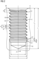
- the tool 2 shown is used to create a threaded hole 5 in a workpiece 6 .
- the tool 2 is a combined tool and produces both the core hole in the workpiece with the specified core hole diameter of the thread and the internal thread in the core hole, ie the thread turn 50 of the internal thread in the lateral wall or inner wall of the core hole.
- the tool is moved into the workpiece 6 in a working movement or a working stroke or a thread-producing movement, which is composed of a rotational movement about the tool axis on the one hand and an axial feed movement along the tool axis.
- FIG 2 shows an embodiment of a threaded hole 5 with a thread turn 50 and a thread profile 55, with a method or a tool according to the invention, for example a tool according to FIG 1 , can be produced.
- the tool 2 is, as for example in FIG 1 shown, on the one hand rotatable or rotationally movable about a tool axis A running through the tool 2 and on the other hand axially or translationally movable along or axially to the tool axis A. These two movements are coordinated or synchronized with one another, preferably by a control unit, in particular a machine controller, while the tool 2 penetrates the workpiece 6 on a surface 60 of the workpiece 6 and to a hole depth LT.
- the tool axis A remains stationary or in a constant position relative to the workpiece 6 while the threaded hole 5 is being produced.
- the thread center axis M of the threaded hole 5 is coaxial with the tool axis A or coincides with it during the process.
- the tool 2 is preferably by means of a coupling area on a tool shank 21 that runs or is formed axially to the tool axis A by means of a rotary drive (not shown), in particular a machine tool and/or drive or machine tool spindle, rotatory or in a rotational movement about its tool axis A in a forward direction of rotation VD and can be driven in an opposite reverse direction of rotation RD. Furthermore, the tool 2 can be moved axially in an axial forward movement VB or an axial backward movement RB relative to the tool axis A, in particular by means of an axial drive, which in turn can be provided in the machine tool and/or drive or machine tool spindle.
- a working area 20 is provided on a free end area of the tool 2 facing away from the coupling area of the shank 21 .
- the workspace 20 includes a drilling area 3 at the front end of the tool 2 and a thread generating area 4 which is offset axially with respect to the tool axis A to the rear of the drilling area 3 or towards the shank 21.
- the drilling area 3 comprises front drilling (main) cutters 30 which can be arranged obliquely, in particular conically, running axially forward and can converge in a drill tip 33 , in particular in a cone tapering towards the drill tip 33 .
- These end drill bits 30 are designed to cut in the forward direction of rotation VD, right-cutting in the illustrated embodiment, and during the forward movement VB with simultaneous rotary movement in the forward direction of rotation VD, material of the workpiece 6, which is located axially in front of the tool 2, is removed by cutting.
- the drilling area 3 preferably also includes guide areas 31 on its outer wall, which can be used to guide the tool 2 in the bore that is produced and for this purpose bear against the core hole wall or are only slightly spaced from it.
- guide areas 31 can be used to guide the tool 2 in the bore that is produced and for this purpose bear against the core hole wall or are only slightly spaced from it.
- circumferential cutters or jacket cutters can also be provided, which machine or prepare the jacket wall of the core hole by removing areas of the workpiece 6 that adjoin radially to the tool axis A to the outside.
- jacket cutting edges can also be used to achieve a sufficient surface quality for the jacket wall or the inner wall of the core hole and, in particular, run predominantly parallel or slightly inclined backwards (to reduce friction) to the tool axis A at a radial distance d/2 from the tool axis A, which corresponds to half the inner diameter of the core hole .
- the guide areas 31 or peripheral or jacket cutting edges can be formed and/or arranged directly adjacent to the front drilling cutting edges 30 or can also be slightly offset axially from them.
- the drilling area 3 thus has an outer diameter or bore diameter d and consequently produces a bore or a core hole with this inner diameter d in the workpiece 6.
- the drill bits 30 and 31 can also be referred to as core hole cutting, since they produce the core hole of the threaded hole 5.
- the outermost to Tool axis A radial dimension of the drilling or core hole cutting edges 30 and 31 determine the core hole inside diameter d.
- the tool 2 comprises a thread generation area 4 with one or more, i.e. a number n greater than or equal to 1, thread generation teeth or thread generation webs.
- thread-generating teeth or thread-generating webs these are arranged offset to one another in the axial direction at least approximately along a helix or helix whose pitch corresponds to the thread pitch P of the internal thread or thread turn 50 to be generated.
- Such an arrangement along a helix or helical line or a thread also includes embodiments in which thread teeth are slightly laterally offset from an ideal line, for example around thread knitting profiles with different processing on the thread flanks or a different distribution or superimposition of the thread knitting profiles on or towards to realize the overall thread profile.
- the only important thing with regard to this arrangement of the thread teeth is that their arrangement is mapped to a thread turn in the workpiece with the same thread pitch P during the working movement.
- two or more thread-generating teeth 41 and 42 are provided, which are offset axially from one another, for example by half a thread pitch P, ie offset in the angular direction by half a revolution or by 180°.
- the thread generating teeth, in particular 41 and 42 protrude further radially from the tool axis A further outwards than the drilling or core hole cutting edges 30 and 31.
- the radial difference between the outermost dimension of the thread generating teeth and the outermost radial dimension of the core hole cutting edges corresponds in particular to the profile depth of the thread profile to be generated Internal thread or, in other words, the difference between the radius D/2 of the thread root and the radius of the core hole d/2.
- the thread profile of the internal thread i.e. the longitudinal section through the thread turn 50 in a sectional plane containing the tool axis A, is generated by the effective thread profile composed or superimposed from the individual effective profiles of the thread-generating teeth, e.g. 41 and 42, when completely passing through the workpiece.
- the thread profile width of the effective thread profile measured in axial projection onto the tool axis A is denoted by c and corresponds to the maximum distance between the flanks of the thread profile.
- the axial distance, measured in axial projection onto the tool axis A, between two consecutive thread profiles of the thread turn 50 is the thread gap b.
- the sum of the thread gap b and the thread width c corresponds to the thread pitch P.
- a first work phase or thread production phase the core hole is produced with the tool 2 using the drilling area 3 and immediately behind it and at least partially simultaneously the thread 50 is produced in the core hole wall using the thread production area 4 .
- the axial feed rate v along the tool axis A is coordinated and synchronized with the rotational speed for the rotary motion around the tool axis A in such a way that the axial feed rate corresponds to the thread pitch P for a full revolution.
- the axial penetration depth (or: the axial feed) T in the direction of the tool axis A measured from the workpiece surface 60 in this first working phase corresponds to the thread depth T G .
- tool 2 is braked in a rotation angle interval in a braking process (or: in a braking movement) in such a way that the axial feed V at a rotation angle of 360°, i.e. at a full revolution, of the Tool 2 is smaller than the thread pitch P and decreases to zero.
- a rotation angle interval in a braking process (or: in a braking movement) in such a way that the axial feed V at a rotation angle of 360°, i.e. at a full revolution, of the Tool 2 is smaller than the thread pitch P and decreases to zero.
- V P
- this braking process takes place in defined partial steps, as will be explained in more detail below.
- This braking movement in the second working phase means that the thread generation area 4 now produces at least one circumferential groove or circumferential groove or circumferential groove in the core hole wall—in a way that is actually atypical or non-functional.
- the process in the second work phase can therefore, in addition to being a braking process, also be referred to as the production of circumferential grooves or production of circumferential grooves or undercut movement, and in the case of a purely cutting tool also as a free-cutting movement.
- the thread generating teeth 41 and 42 are shown with the same outer radius D/2 and preferably the same active thread profile, which already corresponds to the end profile of the thread turn 50 .
- the thread-forming teeth 41 and 42 of the tool according to FIG FIG 1 produce in the second working phase a circumferential groove 53 with the continuous outer diameter D and the axial length a, which results from the total axial advancement of the braking movement in the second working phase up to the reversal point.
- FIG 2 In contrast, two circumferential grooves 51 and 52 are shown, with the first circumferential groove 51 having an outer diameter d′ lying between the core hole diameter d and the outer thread diameter D and the second circumferential groove 52 having an outer diameter which corresponds to the outer diameter D of the thread.
- Such circumferential grooves 51 and 52 can be provided during the second working phase, for example, with two thread-forming teeth 41 and 42 offset by P/2, as for example in FIG 1 shown, are generated, which are modified as follows:
- the first thread generation tooth 41 in FIG 1 only have an outer radius d'/2 and thus be a chamfer or grooving tooth that does not produce the thread turn 50 to the full profile depth or to the final thread root, while the second thread-creating tooth 42 already has the full outer diameter D, i.e. the full thread profile depth generated (full tooth).
- the circumferential groove is thus composed of two partial grooves, namely the first circumferential groove 51 with the smaller diameter, which is produced by the first thread-generating tooth 41, and the second circumferential groove 52, which has the full diameter D and is produced by the second thread-generating tooth 42.
- the axial feed V at full revolution or 360° is reduced in particular by at least b/n compared to P in order to close the thread gap b or no longer generate it, where n is the number of thread generation teeth in the thread generating area 4 is.
- the undercut movement or braking movement could also be carried out in such a way that the outer width of the thread profile, in particular the flanks, is in the circumferential groove are no longer visible or disappear and/or the circumferential groove has only a cylindrical shape. In this way, the ability to screw through the workpiece thread produced could be improved or made possible.
- n 2 with the two thread-generating teeth 41 and 42 or circumferential grooves 51 and 52, so that the axial feed V during the braking process is preferably set to be less than P ⁇ b/2.
- the active thread profile of the thread-generating teeth, here 41 and 42, then no longer generates a thread in the superimposition during the movement, but at least one continuous circumferential groove, which continuously has the outer diameter that corresponds to that of the associated thread-generating tooth on its respective path during the braking movement in the second working phase corresponds.
- T L The total depth or hole depth or total axial dimension of the threaded hole 5 after the second working phase is denoted by T L and essentially corresponds to the sum T G + a of the thread depth T G as the axial feed from the first working phase and the axial groove length a as the axial feed from the second phase of work.
- a reversing or backward movement RB is now initiated directly at the reversal point, with which the tool 2 is initially moved back in a first reversing phase through the circumferential groove(s) 51, 52, 53 to the thread turn 50 and then in a second reversing phase through the thread or the thread 50 is moved outwards from the threaded hole 5 and then the workpiece 6 or is unthreaded.
- the axial feed and the rotary movement of the tool 2 are again synchronized with each other according to the thread pitch P in order not to damage the thread, only that the direction of the axial feed is in the direction of the arrow of the reverse movement RB compared to the direction of the arrow of the Forward or working movement VB is reversed or reversed and the direction of rotation of the rotary movement is also reversed, i.e. instead of the forward direction of rotation VD, the reverse direction of rotation RD is now set.
- the thread axis or central axis of the thread with the thread turn 50 is denoted by M and falls during the entire working movement, i.e. both in the first working phase and in the second working phase, and also during the reversing movement, i.e. both in the first reversing phase and in the second reversing phase, together with the tool axis A of the tool 2 or is coaxial thereto.
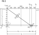
- the 3 to 5 each use a diagram to show an exemplary embodiment of a process (or: procedure) or a control sequence that can be used both to produce a thread in a previously produced core hole in the workpiece or to produce a threaded hole in the workpiece, i.e. in the solid material of the workpiece without prior core drilling, for example a Threaded hole according FIG 2 , can be used.
- a tap or thread forming tool according to the prior art mentioned at the outset can be used.
- a combined drilling and tapping tool such as from the one mentioned above DE 10 2016 008 478 A1 known, or a combined drilling and thread forming tool, as from the aforementioned DE 10 2005 022 503 A1 known, or a tool according to the invention, for example according to FIG 1 , be used.
- the penetration depth (or: vertical or axial coordinate) T is plotted on the vertical axis or ordinate as a coordinate running and measured in the axial direction, i.e. along the tool axis A and the central thread axis M coaxial to the tool axis A, for the axial feed in mm.
- the (added up) angle of rotation ⁇ of the rotary movement of the tool 2 about its tool axis A is plotted in degrees [°] on the horizontal axis or abscissa.
- the angle of rotation ⁇ increases towards positive values during the forward rotational movement VD or in a forward rotational direction and decreases during the reverse rotational movement RD or a reverse rotational direction opposite to the forward rotational direction.
- t 360° corresponds to a complete rotation of tool 2 around its tool axis A.
- the function T (cp) describes the dependency or synchronization of the axial feed movement in the axial coordinate (or: depth in the workpiece 6) T of or with the rotary movement in the coordinate ⁇ and is typically used in a control such as a numerical control or CC control the machine tool, in particular in the form of a previously determined and stored table of values or also as a function for the respective calculation.
- the T coordinate would correspond to the Z axis (spindle axis), with the positive direction running conventionally from the workpiece to the tool, such as in FIG 1 drawn at coordinate T.
- T ⁇ P / 360 ° ⁇ with the thread pitch P.
- the linear section of the function T ( ⁇ ) corresponds to the usual synchronized tapping or tapping kinematics and can be stored in a CNC control, for example, as a preprogrammed path condition (address letter G or G function), e.g. as G33, in particular G331 and G332, where the thread pitch P is entered as an interpolation parameter parallel to the Z axis, typically under the address letter K in the CNC nomenclature.
- a preprogrammed path condition address letter G or G function
- the temporal dependency of the angle of rotation ⁇ (t) as a function of time t and thus the penetration depth T(t) as a function of time t can in principle be varied during the thread production process - even within wide ranges.
- a reversal point UP is reached, at which point the tool 2 comes to a brief standstill both with regard to the rotary movement and with regard to the axial feed movement.
- the axial feed rate is reduced as a function of the angle of rotation, which corresponds to the slope of the graph shown for the function T( ⁇ ), according to a dependency or function that is preferably strictly monotonic (slope always falling) or monotonic (slope falling and possibly also zero in sections), but may also rise slightly again in sections.
- the gradient is preferably reduced successively in a predetermined number n of individually defined, programmed or stored partial steps or braking steps S i , the total number or number n being a natural number with n>1, generally 200>n>2, in particular 20>n > 5 is selected and where i is the counting index for the deceleration step S i and is between 1 and n, ie 1 ⁇ i ⁇ n.
- each deceleration step S i a synchronization of the axial feed T (or the feed rate dT/dt) and the angle of rotation ⁇ (or the rotational speed d(p/dt)) corresponding to the control of a threading process is set or programmed, in that each deceleration step S i with 1 ⁇ i ⁇ n an associated predefined function T i ( ⁇ ) with an associated value interval [T i-1 , T i ] over the associated angle of rotation interval [ ⁇ i-1 , ⁇ i ] is assigned or programmed.
- the function T i ( ⁇ ) is preferably linear, so the graph is (ideally) a straight line.
- the programmed or stored gradient decreases in steps or successively from each deceleration step S i to the next deceleration step S i+1 , ie
- the gradient corresponds in each case to a gradient parameter.
- this pitch parameter is programmed as a thread pitch in the CNC control, ie in particular as an interpolation parameter along the z-axis or the thread axis M in a G33, in particular G331 and G332, path condition.
- the path conditions or G functions already specified in the control programming can be used and only the input parameters for the thread pitch have to be successively changed or reprogrammed.
- P i ⁇ P ie the pitch in the second working phase or during the braking movement AB is smaller than the thread pitch P during the first working phase.
- P i P(n ⁇ i)/n. This applies, for example, to P 1 to P n-1 , in which case a value smaller than P n-1 is selected for P n , for example P n-1 /2.
- P 1 is chosen as close to P as possible.
- P n >0 and as close to 0 as possible is chosen.
- the values of P i can, for example, be selected in such a way that a continuously continued movement into the free-cutting area is possible from the thread pitch movement.
- the speed of the tool should be maintained as far as possible.
- various conditions can be formulated, for example, which can be mapped in approximation functions.
- the angle of rotation range ⁇ for the braking movement AB in the second work phase is generally selected to be smaller than the angle of rotation range ⁇ G for thread production in the first work phase, in particular ⁇ 0.5 ⁇ G and preferably ⁇ 0.2 ⁇ G is selected. This can depend in particular on how large the usable thread length is. Another influencing factor is the intended function in the undercut. If, in addition to pure braking, you also want to make further turns to cut the chips free, you can add more turns (see below for 6 and 7 )
- the penetration depth range (or: the maximum penetration depth) ⁇ T for the braking movement AB in the second working phase is generally chosen to be smaller than the penetration depth range or the thread length TG for thread production in the first working phase, in particular ⁇ T ⁇ 0.5 T G , preferably ⁇ T ⁇ 0.2 T G chosen.
- the penetration depth range ⁇ T for the braking movement AB can be selected to be equal to P.
- a penetration depth range ⁇ T of less than P is also possible in order to keep the thread hole depth smaller, eg 0.5 P or 0.25 P up to 2 P and in exceptional cases also larger.
- FIG 4 now shows an embodiment of a braking movement AB in an enlarged view of the lower right area of the diagram 3 in a rotation angle range ⁇ and an associated penetration depth range ⁇ T.
- [ ⁇ 9 , ⁇ 10 ] and associated with these intervals are the corresponding penetration depth intervals [T 0 , T 1 ], [T 1 , T 2 ], ..., [T i-1 , T i ], [T i , Ti+ 1 ],..., [T 9 , T 10 ], into which the penetration depth range ⁇ T is divided
- a partial step S i corresponds to each interval.
- An associated pitch parameter P i in particular as a thread pitch or interpolation parameter of the CNC control, is now assigned to each of these intervals of each braking step S i , i.e. the two intervals [ ⁇ 0 , ⁇ 1 ] and [T 0 , T 1 ] are assigned the pitch P 1 , the pair of intervals [ ⁇ 1 , ⁇ 2 ] and [T 1 , T 2 ] the slope P 2 and so on up to the slope P 10 for the last pair of intervals [ ⁇ 9 , ⁇ 10 ] and [T 9 , T 10 ] .
- S i remains the Thread pitch P 1 to P 10 constant, so that essentially straight sections of the graph of the function T ( ⁇ ) result, in which a synchronized "thread movement" takes place, i.e. the axial feed rate corresponds to the quotient of P i/ 360°.
- the angular distance ⁇ 2 - ⁇ 1 is smaller than the angular distance ⁇ 3 - ⁇ 2 and the angular distance ⁇ i +1 - ⁇ i is greater than the angular distance ⁇ i - ⁇ i-1 .
- the last section covers the largest angular distance or angular range between the angle of rotation values ⁇ 10 - ⁇ 9 . This corresponds to a continuous deceleration process that is slowed down in each subsection or deceleration step S i .
- the reduction of the rotational speed d ⁇ /dt and the axial feed speed dT/dt to 0 depending on the time t can, for example, take place continuously during the braking movement AB or, for example, only in the last braking step S n or S 10 .
- the curves of the graphs in the deceleration steps S 1 to S 10 of FIG 4 result physically from the inertia of the drive system, in particular the control, including its interpolation routines for smoothing the transitions, and the machine drives and the inertia of the moving components.
- an intermediate step can be carried out, such as a cleaning process.
- you can, for example, remove chip root residues by turning the tool further or clean the circumferential groove of residues of the thread tips in order to get a cleaner cylindrical area. Then a screw could be screwed in even better.
- a reversing movement or backwards movement RB is initiated, which initially comprises an acceleration movement BB in a first reversing phase until it is threaded into the thread 50 and in a second reversing phase a backwards movement RB, in which the tool 2 is threaded outwards in a synchronized manner through the thread 50.
- the cam or function according to 3 used in reverse order or run through is
- the first reversing phase corresponds to the second working phase and the second reversing phase to the first working phase.
- an embodiment for the second work phase such as according to FIG 4 be used in reverse order for the first reversing phase.
- an exemplary embodiment is shown, as in the first reversing phase, starting from the reversal point UP, the same dependency or function T( ⁇ ) in the opposite order for the acceleration movement BB in reversal of the deceleration movement AB, for example according to 3 and 4 can be used.
- the slope parameters also remain the same, only in reverse order, that is, in 5 they are from P 10 to P 9 , P 8 to P 1 for the sections of the control curve according to FIG 4 run through from right to left until the depth value T 0 is reached.
- the new angular value ⁇ 11 is assumed after the angular value ⁇ 10 and the interval [ ⁇ 10 , ⁇ 11 ] corresponds to the interval [T 10 , T 9 ], with the thread pitch P 10 and the subsequent angular interval [ ⁇ 11 , ⁇ 12 ] the penetration depth interval [T 9 , T 8 ] with the corresponding thread pitch P 9 etc. up to the last section of [ ⁇ 19 , ⁇ 20 ] corresponding to [T 1 , T 0 ] with the thread pitch P 1 .
- the values of the penetration depth T are used as input parameters that are measured or specified by the controller or programming, and the associated values of the angle of rotation ⁇ result from the dependency using the assigned gradient parameters P and P i .
- a CNC program for tapping or thread forming can therefore be selected, in particular with a G33, in particular G331 and G332, path condition with thread pitch to be entered, and a sequence or set of values for the penetration depth can now be specified, in which a new Thread pitch parameter is toggled, maintaining the thread pitch parameter until the next penetration depth value.
- a sequence would be e.g.
- the linear curve sections or graph sections are continuously attached to each other, ie the starting points ( ⁇ i , T i ) of each interval correspond to the end points of the respective preceding interval and at the first interval to the end point ( ⁇ 0 , T 0 ) of the linear graph of thread generation.
- These connection points are also referred to as interpolation points.
- curve sections or graph sections can also be selected, which are placed together (or: linked, connected with one another) in a continuously differentiable manner. This means that not only does the starting point of each interval match the end point of the preceding interval, i.e. there is a continuous transition at the connection points between the intervals, but the graph sections or their functions can also be differentiated at these connection points and their derivatives have the same value .
- transition in the angle of rotation ⁇ 0 from the thread-generating movement in the first working phase to the braking movement AB in the second working phase or then correspondingly preferably also from the first reversing phase to the second reversing phase is preferably continuously differentiable or selected with the same gradient
- Examples of functions that are suitable for such a continuously differentiable interpolation are polynomials of a higher degree than 1, in particular of the third degree, such as, for example, cubic splines.
- Spline interpolation can be used here.
- a function that is continuous up to the third derivative can be created, for example.
- a continuous, in particular strictly monotonically or also monotonically decreasing, function for the braking process or at least a predominant part of the braking steps S i for example an exponential function or logarithmic function, can be used
- the values of the angle of rotation ⁇ are used as input parameters that are measured or specified by the controller or programming, and the associated values of the penetration depth T result from the dependency using the gradient parameters P and P i .
- the time can also be specified as an input parameter and the values of the rotation angle ⁇ (t) and the penetration depth T(t) result from the dependency on the time t and the dependency on one another using the slope parameters P and Pi .
- control or synchronization can take place in an open control loop without measuring the process variables penetration depth and angle of rotation.
- a penetration depth value is assigned to each angle of rotation value using a table of values or by calculation based on the stored formulas, and the rotary drive and axial drive are controlled accordingly.
- At least one of the two process variables, penetration depth and angle of rotation can also be measured and the measured values can be fed back into the controller in order to regulate according to the 1 to 3 to realize the target curve shown in a closed control loop.
- the angle of rotation ⁇ is generally determined in the area of the drive, in particular the drive spindle, by means of angle-of-rotation sensors or measurement of physical variables that are clearly related to the angle of rotation. In principle, however, it is also possible to measure the angle of rotation directly on the tool 2 .
- the penetration depth T can be measured by axial position sensors and here again generally on the drive, in particular the drive spindle, or also in a special embodiment on the tool or workpiece itself.
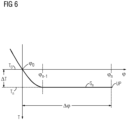
- the direction of rotation of the rotary movement preferably remains the same during the leveling step, ie it is not reversed.
- this reduction is comparatively small.
- the tool runs with a slight reversing feed in the circumferential groove.
- step S n on a circular path or cylindrical path without a gradient or even in step S n-1 with a positive gradient again by a small amount outwards in the workpiece.
- This movement serves in particular to equalize the circumferential groove and to clean the surface of the workpiece, to evacuate the generated threaded hole as completely as possible of chip material and, if necessary, to reduce tension between the workpiece and the tool that was previously built up by the machining forces.
- the step S n as the last step of the braking movement AB in 6 and 7 as well as the penultimate step S n-1 according to FIG 7 can thus also be referred to as an equalization step.
- the total angle of rotation ⁇ n - ⁇ n-1 of the equalization step S n in 6 and ⁇ n - ⁇ n-2 of the equalization step S n and S n-1 in FIG 7 can be freely selected within wide limits, for example between 180° and 2000°, and is generally selected to be larger, for example 3 times larger, than the angle of rotation ⁇ n-1 - ⁇ 0 in 6 or ⁇ n-2 - ⁇ 0 in FIG 7 of the previous monotonically falling section (transition area).
- the leveling step according to the first reversing phase 6 or 7 also partially or completely omitted.
- advantageous movements can be achieved in the transition to the free cut (circumferential groove) and in the free cut itself.
- the working speed of the tool can be as high and constant as possible.
- the machine incl. control
- a geometry that can be screwed through can also be created in the free cut or the circumferential groove.
- the machine In order to keep the speed from the thread high in the undercut, i.e. the circumferential groove, the machine is enabled in particular by a constant movement path of the z-axis (variable T) and axis of rotation (variable ⁇ ), preferably with a high Path speed to realize this movement. This then results in a high and constant speed of the effective tool teeth and cutting edges. This in turn is favorable for uniform chip removal.
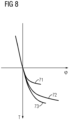
- the 8 to 10 show exemplary embodiments in a diagram in which the penetration depth T is again plotted against the angle of rotation ⁇ for the second working phase (and possibly the first reversing phase).
- FIG 8 shows three embodiments with graphs or curves 71 to 73, in which a constant drilling depth per slope as in the example of FIG 4 is chosen for three different values.
Landscapes
- Engineering & Computer Science (AREA)
- Mechanical Engineering (AREA)
- Drilling Tools (AREA)
- Milling Processes (AREA)
- Forging (AREA)
- Moulds For Moulding Plastics Or The Like (AREA)
Claims (8)
- Procédé de réalisation d'un filetage, en particulier d'un filetage intérieur, avec un pas de filetage (P) prédéfini et avec un profil de filetage (55) prédéfini dans une pièce à usiner (6),a) dans lequel on utilise un outil (2) qui peut tourner autour d'un axe d'outil (A) passant par l'outil (2) et qui est mobile axialement par rapport à l'axe d'outil (A) et qui présente une zone de production de filet (4),b) la zone de production de filet (4) présentant au moins une dent de filet (41, 42) qui est réalisée et disposée de manière adaptée au pas de filet (P) prédéfini, et présentant un profil actif qui correspond au profil de filet (55) du filet (5),c) et dans lequel l'outil (2) est déplacé dans la pièce à usiner (6) ou vers la pièce à usiner (6) dans un mouvement de travail (VB) pendant une première phase de travail,d) le mouvement de travail (VB) comprenant un mouvement de rotation avec un sens de rotation (VD, RD) prédéterminé autour de l'axe d'outil (A) et un mouvement d'avance axial synchronisé avec le mouvement de rotation selon le pas de filetage (P) dans une direction axiale vers l'avant axialement par rapport à l'axe d'outil (A), de telle sorte qu'à une rotation complète de l'outil (2) autour de l'axe d'outil (A) correspond une avance axiale (V) de l'outil (2) selon le pas de filetage (P) prédéterminé,e) dans lequel, pendant le mouvement de travail (VB), la zone de production de filet (4) produit le filet (5),f) l'outil (2) étant déplacé, dans un mouvement de freinage (AB) faisant suite au mouvement de travail (VB), pendant une deuxième phase de travail, plus loin dans la pièce à usiner (6) dans la même direction vers l'avant que lors du mouvement de travail (VB) jusqu'à un point d'inversion (UP),g) le mouvement de freinage (AB) comprenant un mouvement de rotation avec un sens de rotation (VD, RD) constant comme pour le mouvement de travail (VB),h) le mouvement d'avance axiale étant commandé pendant le mouvement de freinage (AB) en fonction de l'angle de rotation du mouvement de rotation de l'outil (2) selon une relation univoque préenregistrée entre l'avance axiale (V) de l'outil (2) et l'angle de rotation, eti) l'avance axiale (V) de l'outil (2) étant, pour une rotation complète, au moins pendant une partie du mouvement de freinage (AB), inférieure en valeur absolue au pas de filetage (P) et nulle au point d'inversion (UP),
caractérisé en ce quej) en ce que, pendant le mouvement de freinage (AB), des fonctions différentes les unes des autres entre l'avance axiale (V) de l'outil (2) et l'angle de rotation sont sélectionnées ou réglées en plusieurs étapes de freinage successives,k) dans lequel, pendant la pluralité d'étapes de freinage, l'avance axiale (V) est une fonction linéaire de l'angle de rotation et dans lequel la pente, c'est-à-dire la dérivée de l'avance axiale par rapport à l'angle de rotation, est constante dans chacune de ces étapes de freinage et diminue en valeur absolue d'une étape de freinage à une étape de freinage suivante. - Procédé selon la revendication 1, dans lequel la vitesse de rotation du mouvement de rotation au point d'inversion (UP) est nulle et/ou dans lequel l'avance axiale totale ou cumulée (V) de l'outil pendant le mouvement de décélération (AB) est choisie entre 0,1 fois et 2 fois le pas de vis (P).
- Procédé selon la revendication 1 ou 2, dans lequel on utilise pour le mouvement de travail (VB) une commande numérique pour un processus de filetage, par exemple une condition de course G33, avec le pas de filetage (P) du filetage (5) et, dans les plusieurs étapes de freinage, on utilise également une, de préférence la même, commande numérique pour un processus de filetage, par exemple une condition de course G33, avec le pas constant respectif comme paramètre de pas de filetage.
- Procédé selon l'une quelconque des revendications 1 à 3, dans lequel les différentes fonctions des étapes de freinage successives sont mises bout à bout de manière continue.
- Procédé selon l'une des revendications précédentes, dans lequel, notamment lors d'une étape d'égalisation, l'avance axiale (V) est nulle pendant le mouvement de freinage (AB) dans un sous-intervalle d'angle de rotation et/ou s'effectue dans un sous-intervalle d'angle de rotation en sens inverse du sens d'avance du mouvement de travail (VB).
- Procédé selon l'une des revendications précédentes, dans lequel, une fois le point d'inversion (UP) atteint, un mouvement d'inversion de l'outil est initié, avec lequel l'outil (2) est déplacé hors de la pièce (6), le mouvement d'inversion comprenant d'abord une première phase d'inversion, avec laquelle la zone de génération de filet (4) de l'outil (2) est ramenée dans le pas de vis (50) du filet (5) généré, et ensuite une deuxième phase d'inversion, pendant laquelle la zone de génération de filet (4) est guidée vers l'extérieur de la pièce (6) à travers le pas de vis (50).
- Procédé selon la revendication 6, dans lequel le mouvement d'inversion est commandé dans la première phase d'inversion avec la même relation univoque, en particulier une fonction ou une séquence de fonctions, entre l'avance axiale (V) de l'outil (2) et l'angle de rotation, mémorisée au préalable, inversée uniquement dans le sens de rotation et le sens d'avance, que dans le mouvement de freinage (AB) pendant une deuxième phase de travail, le cas échéant en omettant ou en raccourcissant l'étape d'égalisation, si elle existe.
- Procédé selon l'une quelconque des revendications précédentes,a) dans lequel on utilise un outil (2) qui peut tourner autour d'un axe d'outil (A) s'étendant à travers l'outil (2) et qui est mobile axialement par rapport à l'axe d'outil (A) et qui présente une zone de perçage (3) à une extrémité avant ou libre et une zone de production de filet (4) qui est décalée axialement par rapport à l'axe d'outil (A) par rapport à la zone de perçage (3) et qui fait saillie radialement vers l'extérieur par rapport à l'axe d'outil (A) plus loin que la zone de perçage (3),b) dans lequel, pendant le mouvement de travail (VB), la zone de perçage (3) de l'outil (2) produit un trou de carotte dans la pièce à usiner (6) et la zone de production de filet (4) produit un filet (50) s'étendant sous le pas de filet prédéterminé (P) dans la paroi intérieure du trou de carotte produit par la zone de perçage (3).
Applications Claiming Priority (2)
| Application Number | Priority Date | Filing Date | Title |
|---|---|---|---|
| DE102018114457 | 2018-06-15 | ||
| PCT/DE2019/100548 WO2019238175A1 (fr) | 2018-06-15 | 2019-06-14 | Procédé de production d'un filetage interne |
Publications (2)
| Publication Number | Publication Date |
|---|---|
| EP3710193A1 EP3710193A1 (fr) | 2020-09-23 |
| EP3710193B1 true EP3710193B1 (fr) | 2023-08-16 |
Family
ID=67107320
Family Applications (1)
| Application Number | Title | Priority Date | Filing Date |
|---|---|---|---|
| EP19734239.7A Active EP3710193B1 (fr) | 2018-06-15 | 2019-06-14 | Procédé de production d'un filetage |
Country Status (6)
| Country | Link |
|---|---|
| US (1) | US11065702B2 (fr) |
| EP (1) | EP3710193B1 (fr) |
| ES (1) | ES2963526T3 (fr) |
| HU (1) | HUE063535T2 (fr) |
| MX (1) | MX2020006980A (fr) |
| WO (1) | WO2019238175A1 (fr) |
Families Citing this family (5)
| Publication number | Priority date | Publication date | Assignee | Title |
|---|---|---|---|---|
| DE102018206545B4 (de) * | 2018-04-27 | 2021-10-14 | Audi Ag | Gewindebohr-Werkzeug und Verfahren zur Erzeugung einer Gewindebohrung |
| DE102021103992A1 (de) * | 2021-02-19 | 2022-08-25 | EMUGE-Werk Richard Glimpel GmbH & Co. KG Fabrik für Präzisionswerkzeuge | Werkzeugkoppelvorrichtung mit Übersetzungseinheit und Verfahren zum Erzeugen eines Gewindes oder eines Gewindelochs |
| US12097560B2 (en) * | 2021-05-07 | 2024-09-24 | Transportation Ip Holdings, Llc | Body and method for locating machining features in additively manufactured parts |
| USD989136S1 (en) * | 2021-07-27 | 2023-06-13 | Anwiner Technology International Inc | Drill head |
| USD1039933S1 (en) * | 2021-12-20 | 2024-08-27 | William Norton | Driver |
Citations (1)
| Publication number | Priority date | Publication date | Assignee | Title |
|---|---|---|---|---|
| US20160357171A1 (en) * | 2015-06-04 | 2016-12-08 | Fanuc Corporation | Device and method of controlling machine tool, to control synchronized operation of spindle axis and feed axis |
Family Cites Families (9)
| Publication number | Priority date | Publication date | Assignee | Title |
|---|---|---|---|---|
| EP1122014B1 (fr) * | 2000-01-31 | 2008-05-14 | Yoshiaki Kakino | Appareil de taraudage et méthode |
| DE102005022503B4 (de) | 2004-09-13 | 2019-10-17 | EMUGE-Werk Richard Glimpel GmbH & Co. KG Fabrik für Präzisionswerkzeuge | Werkzeug und Verfahren zur Erzeugung eines Gewindes |
| JP4703149B2 (ja) * | 2004-09-17 | 2011-06-15 | マキノジェイ株式会社 | ねじ穴加工方法 |
| JP5152443B1 (ja) * | 2012-06-05 | 2013-02-27 | 三菱電機株式会社 | 数値制御装置 |
| EP3213848B1 (fr) * | 2014-10-28 | 2024-09-18 | Mitsubishi Electric Corporation | Dispositif de commande numérique |
| JP6140223B2 (ja) * | 2015-07-29 | 2017-05-31 | ファナック株式会社 | 主軸と送り軸との同期運転を制御する工作機械の制御装置及び制御方法 |
| DE102016008477B4 (de) * | 2016-07-13 | 2020-12-24 | Audi Ag | Verfahren zur Erzeugung einer Gewindebohrung und Gewindewerkzeug zur Durchführung des Verfahrens |
| DE102016008478B4 (de) | 2016-07-13 | 2020-10-15 | Audi Ag | Verfahren zur Erzeugung einer Gewindebohrung |
| DE102017007419B4 (de) * | 2017-08-05 | 2021-08-12 | Audi Ag | Verfahren zur Erzeugung einer Gewindebohrung |
-
2019
- 2019-06-14 EP EP19734239.7A patent/EP3710193B1/fr active Active
- 2019-06-14 HU HUE19734239A patent/HUE063535T2/hu unknown
- 2019-06-14 US US16/961,629 patent/US11065702B2/en active Active
- 2019-06-14 ES ES19734239T patent/ES2963526T3/es active Active
- 2019-06-14 WO PCT/DE2019/100548 patent/WO2019238175A1/fr not_active Ceased
- 2019-06-14 MX MX2020006980A patent/MX2020006980A/es unknown
Patent Citations (1)
| Publication number | Priority date | Publication date | Assignee | Title |
|---|---|---|---|---|
| US20160357171A1 (en) * | 2015-06-04 | 2016-12-08 | Fanuc Corporation | Device and method of controlling machine tool, to control synchronized operation of spindle axis and feed axis |
Also Published As
| Publication number | Publication date |
|---|---|
| US11065702B2 (en) | 2021-07-20 |
| MX2020006980A (es) | 2020-09-09 |
| HUE063535T2 (hu) | 2024-01-28 |
| ES2963526T3 (es) | 2024-03-27 |
| US20200338655A1 (en) | 2020-10-29 |
| WO2019238175A1 (fr) | 2019-12-19 |
| EP3710193A1 (fr) | 2020-09-23 |
Similar Documents
| Publication | Publication Date | Title |
|---|---|---|
| EP3710194B1 (fr) | Outil et procédé permettant de produire un filetage, en particulier un filetage intérieur | |
| EP3710193B1 (fr) | Procédé de production d'un filetage | |
| EP2861373B1 (fr) | Procédé et outil de création d'un filetage dans une pièce | |
| EP0355678A2 (fr) | Fraise à tarauder | |
| DE102005022503B4 (de) | Werkzeug und Verfahren zur Erzeugung eines Gewindes | |
| DE102019124707B4 (de) | Verfahren zum Erzeugen eines Gewindes mit Übersetzungseinheit | |
| DE102019124679A1 (de) | Verfahren zum Erzeugen eines Durchgangsgewindes | |
| DE102007060554A1 (de) | Verfahren und Werkzeug zur Erzeugung eines Außengewindes | |
| EP2651584B1 (fr) | Procédé pour produire un taraudage dans une pièce d'oeuvre | |
| DE102014112162B4 (de) | Werkzeug und ein Verfahren zum Bearbeiten eines Werkstücks, insbesondere beim oder zum Erzeugen eines Gewindes | |
| EP3544758B1 (fr) | Taraud travaillant par refoulement | |
| DE102005019921A1 (de) | Werkzeug und Verfahren zur Erzeugung oder Nachbearbeitung eines Gewindes | |
| EP3921106A1 (fr) | Outil et procédé permettant de produire un trou fileté avec des brise-copeaux | |
| DE102016114631B4 (de) | Verfahren und Computerprogrammprodukt zur Erzeugung von Gewinden in Bauteilen | |
| DE102006036434B4 (de) | Verfahren zum Erzeugen eines Gewindes in einem Werkstück | |
| DE102011015879A1 (de) | Verfahren zum Herstellen eines Gewindes in einem Werkstück | |
| DE102019124800B4 (de) | Verfahren zum Erzeugen eines Gewindes, insbesondere eines Innengewindes, mit Hartmetall | |
| DE102005042409B4 (de) | Werkzeug und Verfahren zur Erzeugung oder Nachbearbeitung eines Gewindes, insbesondere eines Innengewindes | |
| DE102005037119B4 (de) | Verfahren zum Erzeugen eines Gewindes in einem Werkstück | |
| DE102006028380B4 (de) | Werkzeug und Verfahren zur Erzeugung oder Nachbearbeitung eines Gewindes mit Furchflächenaufteilung | |
| DE102015102293A1 (de) | Gewindeformwerkzeug mit Gewindeformprofil mit speziellem Furchkeilwinkel | |
| DE102015100615A1 (de) | Werkzeug und Verfahren zur Herstellung einer Nut in einem Kernloch | |
| DE102005010543A1 (de) | Werkzeug und Verfahren zur Erzeugung oder Nachbearbeitung eines Gewindes |
Legal Events
| Date | Code | Title | Description |
|---|---|---|---|
| STAA | Information on the status of an ep patent application or granted ep patent |
Free format text: STATUS: UNKNOWN |
|
| STAA | Information on the status of an ep patent application or granted ep patent |
Free format text: STATUS: THE INTERNATIONAL PUBLICATION HAS BEEN MADE |
|
| PUAI | Public reference made under article 153(3) epc to a published international application that has entered the european phase |
Free format text: ORIGINAL CODE: 0009012 |
|
| STAA | Information on the status of an ep patent application or granted ep patent |
Free format text: STATUS: REQUEST FOR EXAMINATION WAS MADE |
|
| 17P | Request for examination filed |
Effective date: 20200618 |
|
| AK | Designated contracting states |
Kind code of ref document: A1 Designated state(s): AL AT BE BG CH CY CZ DE DK EE ES FI FR GB GR HR HU IE IS IT LI LT LU LV MC MK MT NL NO PL PT RO RS SE SI SK SM TR |
|
| AX | Request for extension of the european patent |
Extension state: BA ME |
|
| DAV | Request for validation of the european patent (deleted) | ||
| DAX | Request for extension of the european patent (deleted) | ||
| GRAP | Despatch of communication of intention to grant a patent |
Free format text: ORIGINAL CODE: EPIDOSNIGR1 |
|
| STAA | Information on the status of an ep patent application or granted ep patent |
Free format text: STATUS: GRANT OF PATENT IS INTENDED |
|
| INTG | Intention to grant announced |
Effective date: 20230419 |
|
| GRAS | Grant fee paid |
Free format text: ORIGINAL CODE: EPIDOSNIGR3 |
|
| GRAA | (expected) grant |
Free format text: ORIGINAL CODE: 0009210 |
|
| STAA | Information on the status of an ep patent application or granted ep patent |
Free format text: STATUS: THE PATENT HAS BEEN GRANTED |
|
| AK | Designated contracting states |
Kind code of ref document: B1 Designated state(s): AL AT BE BG CH CY CZ DE DK EE ES FI FR GB GR HR HU IE IS IT LI LT LU LV MC MK MT NL NO PL PT RO RS SE SI SK SM TR |
|
| REG | Reference to a national code |
Ref country code: CH Ref legal event code: EP |
|
| REG | Reference to a national code |
Ref country code: DE Ref legal event code: R096 Ref document number: 502019008969 Country of ref document: DE |
|
| REG | Reference to a national code |
Ref country code: IE Ref legal event code: FG4D Free format text: LANGUAGE OF EP DOCUMENT: GERMAN |
|
| REG | Reference to a national code |
Ref country code: SE Ref legal event code: TRGR |
|
| REG | Reference to a national code |
Ref country code: LT Ref legal event code: MG9D |
|
| REG | Reference to a national code |
Ref country code: NL Ref legal event code: MP Effective date: 20230816 |
|
| PG25 | Lapsed in a contracting state [announced via postgrant information from national office to epo] |
Ref country code: GR Free format text: LAPSE BECAUSE OF FAILURE TO SUBMIT A TRANSLATION OF THE DESCRIPTION OR TO PAY THE FEE WITHIN THE PRESCRIBED TIME-LIMIT Effective date: 20231117 |
|
| PG25 | Lapsed in a contracting state [announced via postgrant information from national office to epo] |
Ref country code: IS Free format text: LAPSE BECAUSE OF FAILURE TO SUBMIT A TRANSLATION OF THE DESCRIPTION OR TO PAY THE FEE WITHIN THE PRESCRIBED TIME-LIMIT Effective date: 20231216 |
|
| REG | Reference to a national code |
Ref country code: HU Ref legal event code: AG4A Ref document number: E063535 Country of ref document: HU |
|
| PG25 | Lapsed in a contracting state [announced via postgrant information from national office to epo] |
Ref country code: RS Free format text: LAPSE BECAUSE OF FAILURE TO SUBMIT A TRANSLATION OF THE DESCRIPTION OR TO PAY THE FEE WITHIN THE PRESCRIBED TIME-LIMIT Effective date: 20230816 Ref country code: PT Free format text: LAPSE BECAUSE OF FAILURE TO SUBMIT A TRANSLATION OF THE DESCRIPTION OR TO PAY THE FEE WITHIN THE PRESCRIBED TIME-LIMIT Effective date: 20231218 Ref country code: NO Free format text: LAPSE BECAUSE OF FAILURE TO SUBMIT A TRANSLATION OF THE DESCRIPTION OR TO PAY THE FEE WITHIN THE PRESCRIBED TIME-LIMIT Effective date: 20231116 Ref country code: NL Free format text: LAPSE BECAUSE OF FAILURE TO SUBMIT A TRANSLATION OF THE DESCRIPTION OR TO PAY THE FEE WITHIN THE PRESCRIBED TIME-LIMIT Effective date: 20230816 Ref country code: LV Free format text: LAPSE BECAUSE OF FAILURE TO SUBMIT A TRANSLATION OF THE DESCRIPTION OR TO PAY THE FEE WITHIN THE PRESCRIBED TIME-LIMIT Effective date: 20230816 Ref country code: LT Free format text: LAPSE BECAUSE OF FAILURE TO SUBMIT A TRANSLATION OF THE DESCRIPTION OR TO PAY THE FEE WITHIN THE PRESCRIBED TIME-LIMIT Effective date: 20230816 Ref country code: IS Free format text: LAPSE BECAUSE OF FAILURE TO SUBMIT A TRANSLATION OF THE DESCRIPTION OR TO PAY THE FEE WITHIN THE PRESCRIBED TIME-LIMIT Effective date: 20231216 Ref country code: HR Free format text: LAPSE BECAUSE OF FAILURE TO SUBMIT A TRANSLATION OF THE DESCRIPTION OR TO PAY THE FEE WITHIN THE PRESCRIBED TIME-LIMIT Effective date: 20230816 Ref country code: GR Free format text: LAPSE BECAUSE OF FAILURE TO SUBMIT A TRANSLATION OF THE DESCRIPTION OR TO PAY THE FEE WITHIN THE PRESCRIBED TIME-LIMIT Effective date: 20231117 Ref country code: FI Free format text: LAPSE BECAUSE OF FAILURE TO SUBMIT A TRANSLATION OF THE DESCRIPTION OR TO PAY THE FEE WITHIN THE PRESCRIBED TIME-LIMIT Effective date: 20230816 |
|
| PG25 | Lapsed in a contracting state [announced via postgrant information from national office to epo] |
Ref country code: PL Free format text: LAPSE BECAUSE OF FAILURE TO SUBMIT A TRANSLATION OF THE DESCRIPTION OR TO PAY THE FEE WITHIN THE PRESCRIBED TIME-LIMIT Effective date: 20230816 |
|
| REG | Reference to a national code |
Ref country code: ES Ref legal event code: FG2A Ref document number: 2963526 Country of ref document: ES Kind code of ref document: T3 Effective date: 20240327 |
|
| PG25 | Lapsed in a contracting state [announced via postgrant information from national office to epo] |
Ref country code: SM Free format text: LAPSE BECAUSE OF FAILURE TO SUBMIT A TRANSLATION OF THE DESCRIPTION OR TO PAY THE FEE WITHIN THE PRESCRIBED TIME-LIMIT Effective date: 20230816 Ref country code: RO Free format text: LAPSE BECAUSE OF FAILURE TO SUBMIT A TRANSLATION OF THE DESCRIPTION OR TO PAY THE FEE WITHIN THE PRESCRIBED TIME-LIMIT Effective date: 20230816 Ref country code: EE Free format text: LAPSE BECAUSE OF FAILURE TO SUBMIT A TRANSLATION OF THE DESCRIPTION OR TO PAY THE FEE WITHIN THE PRESCRIBED TIME-LIMIT Effective date: 20230816 Ref country code: DK Free format text: LAPSE BECAUSE OF FAILURE TO SUBMIT A TRANSLATION OF THE DESCRIPTION OR TO PAY THE FEE WITHIN THE PRESCRIBED TIME-LIMIT Effective date: 20230816 Ref country code: CZ Free format text: LAPSE BECAUSE OF FAILURE TO SUBMIT A TRANSLATION OF THE DESCRIPTION OR TO PAY THE FEE WITHIN THE PRESCRIBED TIME-LIMIT Effective date: 20230816 Ref country code: SK Free format text: LAPSE BECAUSE OF FAILURE TO SUBMIT A TRANSLATION OF THE DESCRIPTION OR TO PAY THE FEE WITHIN THE PRESCRIBED TIME-LIMIT Effective date: 20230816 |
|
| REG | Reference to a national code |
Ref country code: DE Ref legal event code: R097 Ref document number: 502019008969 Country of ref document: DE |
|
| PLBE | No opposition filed within time limit |
Free format text: ORIGINAL CODE: 0009261 |
|
| STAA | Information on the status of an ep patent application or granted ep patent |
Free format text: STATUS: NO OPPOSITION FILED WITHIN TIME LIMIT |
|
| PGFP | Annual fee paid to national office [announced via postgrant information from national office to epo] |
Ref country code: GB Payment date: 20240618 Year of fee payment: 6 |
|
| 26N | No opposition filed |
Effective date: 20240517 |
|
| PG25 | Lapsed in a contracting state [announced via postgrant information from national office to epo] |
Ref country code: SI Free format text: LAPSE BECAUSE OF FAILURE TO SUBMIT A TRANSLATION OF THE DESCRIPTION OR TO PAY THE FEE WITHIN THE PRESCRIBED TIME-LIMIT Effective date: 20230816 |
|
| PG25 | Lapsed in a contracting state [announced via postgrant information from national office to epo] |
Ref country code: BG Free format text: LAPSE BECAUSE OF FAILURE TO SUBMIT A TRANSLATION OF THE DESCRIPTION OR TO PAY THE FEE WITHIN THE PRESCRIBED TIME-LIMIT Effective date: 20230816 |
|
| PG25 | Lapsed in a contracting state [announced via postgrant information from national office to epo] |
Ref country code: BG Free format text: LAPSE BECAUSE OF FAILURE TO SUBMIT A TRANSLATION OF THE DESCRIPTION OR TO PAY THE FEE WITHIN THE PRESCRIBED TIME-LIMIT Effective date: 20230816 |
|
| PG25 | Lapsed in a contracting state [announced via postgrant information from national office to epo] |
Ref country code: MC Free format text: LAPSE BECAUSE OF FAILURE TO SUBMIT A TRANSLATION OF THE DESCRIPTION OR TO PAY THE FEE WITHIN THE PRESCRIBED TIME-LIMIT Effective date: 20230816 |
|
| PG25 | Lapsed in a contracting state [announced via postgrant information from national office to epo] |
Ref country code: LU Free format text: LAPSE BECAUSE OF NON-PAYMENT OF DUE FEES Effective date: 20240614 |
|
| PG25 | Lapsed in a contracting state [announced via postgrant information from national office to epo] |
Ref country code: IE Free format text: LAPSE BECAUSE OF NON-PAYMENT OF DUE FEES Effective date: 20240614 |
|
| PG25 | Lapsed in a contracting state [announced via postgrant information from national office to epo] |
Ref country code: BE Free format text: LAPSE BECAUSE OF NON-PAYMENT OF DUE FEES Effective date: 20240630 |
|
| REG | Reference to a national code |
Ref country code: BE Ref legal event code: MM Effective date: 20240630 |
|
| PGFP | Annual fee paid to national office [announced via postgrant information from national office to epo] |
Ref country code: HU Payment date: 20250612 Year of fee payment: 7 Ref country code: FR Payment date: 20250624 Year of fee payment: 7 |
|
| PGFP | Annual fee paid to national office [announced via postgrant information from national office to epo] |
Ref country code: SE Payment date: 20250619 Year of fee payment: 7 |
|
| REG | Reference to a national code |
Ref country code: AT Ref legal event code: MM01 Ref document number: 1599555 Country of ref document: AT Kind code of ref document: T Effective date: 20240614 |
|
| PGFP | Annual fee paid to national office [announced via postgrant information from national office to epo] |
Ref country code: ES Payment date: 20250710 Year of fee payment: 7 |
|
| PGFP | Annual fee paid to national office [announced via postgrant information from national office to epo] |
Ref country code: DE Payment date: 20250627 Year of fee payment: 7 |
|
| PGFP | Annual fee paid to national office [announced via postgrant information from national office to epo] |
Ref country code: IT Payment date: 20250623 Year of fee payment: 7 |
|
| PG25 | Lapsed in a contracting state [announced via postgrant information from national office to epo] |
Ref country code: AT Free format text: LAPSE BECAUSE OF NON-PAYMENT OF DUE FEES Effective date: 20240614 |
|
| PGFP | Annual fee paid to national office [announced via postgrant information from national office to epo] |
Ref country code: CH Payment date: 20250701 Year of fee payment: 7 |
|
| PG25 | Lapsed in a contracting state [announced via postgrant information from national office to epo] |
Ref country code: CY Free format text: LAPSE BECAUSE OF FAILURE TO SUBMIT A TRANSLATION OF THE DESCRIPTION OR TO PAY THE FEE WITHIN THE PRESCRIBED TIME-LIMIT; INVALID AB INITIO Effective date: 20190614 |
|
| GBPC | Gb: european patent ceased through non-payment of renewal fee |
Effective date: 20250614 |