EP3710199B1 - Dispositif et procédé pour déterminer la position et/ou l'orientation d'une pièce - Google Patents
Dispositif et procédé pour déterminer la position et/ou l'orientation d'une pièce Download PDFInfo
- Publication number
- EP3710199B1 EP3710199B1 EP18799485.0A EP18799485A EP3710199B1 EP 3710199 B1 EP3710199 B1 EP 3710199B1 EP 18799485 A EP18799485 A EP 18799485A EP 3710199 B1 EP3710199 B1 EP 3710199B1
- Authority
- EP
- European Patent Office
- Prior art keywords
- workpiece
- unit
- radiation source
- electromagnetic radiation
- radiation
- Prior art date
- Legal status (The legal status is an assumption and is not a legal conclusion. Google has not performed a legal analysis and makes no representation as to the accuracy of the status listed.)
- Active
Links
Images


Classifications
-
- B—PERFORMING OPERATIONS; TRANSPORTING
- B23—MACHINE TOOLS; METAL-WORKING NOT OTHERWISE PROVIDED FOR
- B23Q—DETAILS, COMPONENTS, OR ACCESSORIES FOR MACHINE TOOLS, e.g. ARRANGEMENTS FOR COPYING OR CONTROLLING; MACHINE TOOLS IN GENERAL CHARACTERISED BY THE CONSTRUCTION OF PARTICULAR DETAILS OR COMPONENTS; COMBINATIONS OR ASSOCIATIONS OF METAL-WORKING MACHINES, NOT DIRECTED TO A PARTICULAR RESULT
- B23Q17/00—Arrangements for observing, indicating or measuring on machine tools
- B23Q17/24—Arrangements for observing, indicating or measuring on machine tools using optics or electromagnetic waves
- B23Q17/2452—Arrangements for observing, indicating or measuring on machine tools using optics or electromagnetic waves for measuring features or for detecting a condition of machine parts, tools or workpieces
- B23Q17/2471—Arrangements for observing, indicating or measuring on machine tools using optics or electromagnetic waves for measuring features or for detecting a condition of machine parts, tools or workpieces of workpieces
-
- B—PERFORMING OPERATIONS; TRANSPORTING
- B23—MACHINE TOOLS; METAL-WORKING NOT OTHERWISE PROVIDED FOR
- B23Q—DETAILS, COMPONENTS, OR ACCESSORIES FOR MACHINE TOOLS, e.g. ARRANGEMENTS FOR COPYING OR CONTROLLING; MACHINE TOOLS IN GENERAL CHARACTERISED BY THE CONSTRUCTION OF PARTICULAR DETAILS OR COMPONENTS; COMBINATIONS OR ASSOCIATIONS OF METAL-WORKING MACHINES, NOT DIRECTED TO A PARTICULAR RESULT
- B23Q17/00—Arrangements for observing, indicating or measuring on machine tools
- B23Q17/22—Arrangements for observing, indicating or measuring on machine tools for indicating or measuring existing or desired position of tool or work
- B23Q17/2233—Arrangements for observing, indicating or measuring on machine tools for indicating or measuring existing or desired position of tool or work for adjusting the tool relative to the workpiece
-
- B—PERFORMING OPERATIONS; TRANSPORTING
- B23—MACHINE TOOLS; METAL-WORKING NOT OTHERWISE PROVIDED FOR
- B23Q—DETAILS, COMPONENTS, OR ACCESSORIES FOR MACHINE TOOLS, e.g. ARRANGEMENTS FOR COPYING OR CONTROLLING; MACHINE TOOLS IN GENERAL CHARACTERISED BY THE CONSTRUCTION OF PARTICULAR DETAILS OR COMPONENTS; COMBINATIONS OR ASSOCIATIONS OF METAL-WORKING MACHINES, NOT DIRECTED TO A PARTICULAR RESULT
- B23Q17/00—Arrangements for observing, indicating or measuring on machine tools
- B23Q17/24—Arrangements for observing, indicating or measuring on machine tools using optics or electromagnetic waves
- B23Q17/2428—Arrangements for observing, indicating or measuring on machine tools using optics or electromagnetic waves for measuring existing positions of tools or workpieces
-
- G—PHYSICS
- G01—MEASURING; TESTING
- G01B—MEASURING LENGTH, THICKNESS OR SIMILAR LINEAR DIMENSIONS; MEASURING ANGLES; MEASURING AREAS; MEASURING IRREGULARITIES OF SURFACES OR CONTOURS
- G01B11/00—Measuring arrangements characterised by the use of optical techniques
- G01B11/002—Measuring arrangements characterised by the use of optical techniques for measuring two or more coordinates
-
- G—PHYSICS
- G01—MEASURING; TESTING
- G01B—MEASURING LENGTH, THICKNESS OR SIMILAR LINEAR DIMENSIONS; MEASURING ANGLES; MEASURING AREAS; MEASURING IRREGULARITIES OF SURFACES OR CONTOURS
- G01B11/00—Measuring arrangements characterised by the use of optical techniques
- G01B11/02—Measuring arrangements characterised by the use of optical techniques for measuring length, width or thickness
- G01B11/026—Measuring arrangements characterised by the use of optical techniques for measuring length, width or thickness by measuring distance between sensor and object
Definitions
- the present invention relates to a device and a method for determining a position and / or orientation of a workpiece.
- a laser light source is often used which is set up to generate one or more lines of light on the surface of the workpiece during operation. The lines of light can then be detected by means of an optical sensor and evaluated by a processing unit connected downstream of the sensor on the basis of an image processing algorithm.
- the invention enriches the prior art in this regard, as Devices and methods according to the invention instead of a single radiation source comprise / use a radiation source pair or a beam splitter, which makes it easier to radiate electromagnetic radiation from different directions onto (partially) overlapping (in particular linear) areas of the surface, so that due to the geometry of the workpiece Shadowing effects can be reduced or avoided.
- the radiation sources or the beam splitter unit are set up to focus electromagnetic radiation on two directly adjacent or at least partially overlapping spatial curves during operation of the device or to radiate the electromagnetic radiation along two directly adjacent or intersecting surfaces.
- a device further comprises a sensor unit which is arranged in accordance with a defined positional relationship to the radiation sources or the beam splitter unit and which is set up to and / or from electromagnetic radiation emitted by the radiation source or radiation sources and reflected on a surface of the workpiece during operation of the device to detect electromagnetic radiation emitted from the surface of the workpiece, and a processing unit which is set up to determine the position and / or orientation of the workpiece relative to the processing unit on the basis of the detected electromagnetic radiation.
- the processing unit is set up to output an error signal if a distance between a first reflection track of the electromagnetic radiation on a surface, particularly preferably the surface of the workpiece, and a second reflection track of the electromagnetic radiation on the surface is outside a tolerance range.
- workpiece as used in the description and the claims, is to be understood in particular as an object made of a solid material that is to be changed by machining, e.g. B. material removed, material changed in its structure or (same or different) material is added (such as drilling, milling, welding, additive manufacturing, coating, etc.).
- processing unit as used in the description and the claims, is to be understood in particular as a group of components by which the change in the object is to be effected by z. B. the component group or parts of the component group act mechanically on the object or supply the object with energy or material.
- the term “radiation source” as used in the description and the claims is to be understood in particular as one or more diodes emitting electromagnetic radiation or a laser.
- the term “beam splitter unit” as used in the description and the claims is to be understood in particular as an optical assembly that separates a single light beam into two partial beams (for example by means of a partially transparent mirror).
- the beam splitter unit can have one or more optical components for deflecting one or both partial beams.
- the term “sensor unit” as used in the description and the claims is to be understood in particular as a component group which has one or more charge-coupled components (CCD sensors) or one or more CMOS components (CMOS sensors) .
- the component group can also include devices for detecting the temperature and / or deformation (e.g. a strain gauge) of the workpiece surface in order to measure not only the reflected electromagnetic radiation but also the heating / expansion of the workpiece (caused by the electromagnetic radiation) and when determining the position and / or to be able to take into account / use alignment of the workpiece relative to the machining unit.
- the space curves preferably lie in one plane or the surfaces are flat.
- the space curves are preferably straight.
- the first radiation source and / or the second radiation source can have a laser or an LED matrix and optical components arranged in the beam path that focus the electromagnetic radiation on a line (for example a line laser).
- a line for example a line laser
- the sensor unit preferably comprises a mirror arrangement which extends along the two directly adjoining or at least partially overlapping spatial curves or along the two intersecting surfaces and allows the electromagnetic radiation to be detected from different perspectives.
- a sensor of the sensor unit is preferably arranged on a bisector of a connecting line between the first radiation source and the second radiation source and / or the sensor unit fulfills the Scheimpflug condition.
- the device preferably has a measuring unit comprising the first radiation source, the second radiation source or the beam splitter unit and the sensor unit, the measuring unit being rotatably mounted in the device about an axis of rotation.
- the measuring unit can be pivotable about the machining unit or the receptacle, as a result of which the need to reposition the machining unit in order to align the measuring unit can be avoided during operation.
- the first radiation source, the second radiation source or the beam splitter unit and the sensor unit are preferably included in one measuring unit and the device has a plurality of such measuring units.
- measuring units can avoid the need to reposition the machining unit during operation, as may be necessary for aligning the measuring unit, for example, when a single measuring unit is present, which is arranged in a fixed position and in a fixed position relative to the machining unit.
- the beam paths of the measuring units preferably intersect.
- a beam curtain can be generated which partially or completely encloses the machining unit and which, with regard to the positioning of the machining unit for aligning a measuring unit, enables a largely or completely direction-independent machining of the workpiece.
- a method for determining a position and / or alignment of a workpiece comprises generating one or more pairs of reflection lines, each pair of reflection lines comprising two directly adjacent or at least partially overlapping and / or parallel reflection lines, particularly preferably lines of light, which generated by electromagnetic radiation emitted onto the surface from different directions.
- a method according to the invention further comprises detecting the reflection lines and determining the position and / or orientation of the workpiece by means of triangulation on the basis of the reflection lines.
- a method according to the invention further comprises determining a distance between the reflection lines of a pair of reflection lines and outputting an error signal if the distance is outside a tolerance range.
- reflection lines of different reflection line pairs intersect on the surface of the workpiece and / or include angles of the same size.
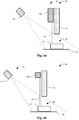
- Fig. 1 shows a schematic front view of a device 10 for determining the relative position and alignment between a processing unit 12 (process head) and a workpiece 14 to be processed by the processing unit 12.
- the device 10 comprises a first radiation source 16a and a second radiation source 16b for structured illumination of the workpiece 14.
- the radiation pattern projected onto the workpiece 14 (e.g. a line or a grid) is composed of two at least partially overlapping and, depending on the workpiece geometry, mutually complementary partial patterns that are generated by the incidence of electromagnetic radiation from different spatial directions.
- the spatial directions from which the electromagnetic rays impinge on the workpiece 14 are shown in FIG Fig. 1a
- the example shown is divided into two non-overlapping (spatial direction) areas which result from the different positions of the radiation sources 16a, 16b.
- the device 10 comprises a Sensor unit 18 with a sensor (for example a CCD or CMOS sensor) for detecting electromagnetic radiation and an upstream optics which images the workpiece surface onto the sensor surface.
- the upstream optics are preferably aligned in such a way that the Scheimpflug condition (image plane, projection plane and objective plane intersect in a straight line) with regard to the structured illumination is (at least approximately) fulfilled.
- the sensor unit 18 can be arranged or configured in such a way that the Scheimpflug condition with regard to the (surface of the) workpiece support 20 (as a projection plane ) is fulfilled, or the sensor unit 18 or the upstream optics can be rotated about an axis parallel to the workpiece support 20 in order to be able to adapt the device 10 to different workpiece geometries.
- Figure 1b shows a modification of the in Fig. 1a shown device 10, in which instead of two radiation sources 16a, 16b, a single radiation source 16 is provided, the electromagnetic radiation emitted by the radiation source 16 by means of a beam splitter unit 22 along different beam paths 26a, 26b (where in Figure 1b for the sake of clarity, only a single beam is shown) is directed.
- the beam splitter unit 22 can, for example, as in FIG Figure 1b shown have a partially (or semitransparent) mirror 22a and a further mirror 22b, which split the electromagnetic radiation emitted by the radiation source 16 and from different spatial directions (which on average correspond to the directions of the dashed lines hitting the surface of the workpiece 14 ) onto the surface of the workpiece 14.
- Fig. 2a shows another view of the in Fig. 1a
- the radiation sources 16a, 16b and the sensor unit 18 are arranged on one side (next to) the processing unit 12 and the radiation sources 16a, 16b (as also in FIG Fig. 1a shown) are aligned such that the beam path 26 falls perpendicularly onto the surface of the workpiece 14 or the workpiece support 20.
- the radiation sources 16a, 16b (as for example in Fig. 4 , Fig. 6 and Fig. 8 illustrated) also be inclined towards a work area 28 (e.g. a workpiece section / area to be processed or a process point) (i.e. not aligned perpendicular to the workpiece support 20 on average), whereby a distance between the structured lighting and the work area 28 may be ( further) can be reduced.
- a work area 28 e.g. a workpiece section / area to be processed or a process point
- the radiation sources 16a, 16b and the sensor unit 18 can be designed as a measuring unit 30 which is connected to the machining unit 12 in such a way that it is moved along with the machining unit 12 (when the machining unit 12 moves).
- Figure 2b shows another view of the in Figure 1b
- the device 10 shown here is analogous to that in Fig. 2a It can be seen that the radiation source 16, the beam splitter unit 22 and the sensor unit 18 are arranged on one side (next to) the processing unit 12 and (as in FIG Figure 1b shown) the beam splitter unit 22 is aligned such that the beam path 26 falls perpendicularly onto the surface of the workpiece 14 or the workpiece support 20 (this being as in connection with Fig. 2a explained alternatively can also be inclined towards the work area 28).
- the radiation source 16, the beam splitter unit 22 and the sensor unit 18 can be designed as a measuring unit 30 which is connected to the processing unit 12 in such a way that ( during a movement of the processing unit 12) is moved along with it.
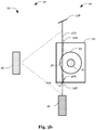
- Fig. 3a shows another view of the in Fig. 1a device 10 shown, according to a first embodiment.
- the electromagnetic radiation is emitted along two partially intersecting surfaces 32a, 32b, the cutting line or surface formed thereby at least partially sweeping over the workpiece surface.
- the electromagnetic radiation is focused on two spatial curves 34a, 34b, which run (at least in sections) along the surface of the workpiece support 20 or along the surface of the workpiece 14, as a result of which a reflection track 36 that can be detected by the sensor unit 18 is formed on the surface of the workpiece 14 a reflection line is generated.
- An (undesired) offset can occur between the spatial curves 34a, 34b, which widening or blurring the reflection track 36.
- a processing unit connected downstream of the sensor unit 18 can make a determination of the position and / or orientation of a workpiece 14 relative to the processing unit 12 a calculation of the position and / or orientation of the workpiece 14 dependent thereon, whether the offset exceeds a certain threshold value or output an error message when the threshold value is exceeded. Furthermore (before determining the position and / or orientation of the workpiece 14 relative to the machining unit 12 or when the threshold value is exceeded) a Calibration routine can be carried out, which is aimed at reducing the offset at least below the threshold value. As part of the calibration routine, for example, one or both radiation sources 16a, 16b (or optical components of the radiation sources 16a, 16b) can be aligned / adjusted.
- the position and, given a corresponding geometry of the workpiece 14, also the alignment of the workpiece 14 can be determined by means of triangulation.
- the position and / or orientation of the workpiece 14 relative to the machining unit 12 can then be used to position / align the machining unit 12 relative to the workpiece 14 at the beginning or during the machining of the workpiece 14, or to continuously monitor and / or monitor the relative position and / or orientation to control.
- unevenness in the surface of the workpiece 14 can be detected (and processed / compensated) or the relative movement between the workpiece 14 and the processing unit 12 can be regulated so that (in sections) a constant distance between the surface and the workpiece 14 and the processing unit 12 is maintained, which, for example, facilitates the programming of the machining unit 12 (or a control unit controlling the machining unit 12) with regard to free-form surfaces to be machined, since it is then sufficient to program flat paths.
- thermal radiation emitted by the workpiece 14 can also be detected.
- the detected thermal radiation can, for example, make it possible to determine an expansion of the workpiece 14 and to adjust the positioning / alignment of the machining unit 12 relative to the workpiece 14 accordingly.
- the thermal radiation can be used to improve the detection of the reflection track 36 in that local heating of the workpiece surface caused by the electromagnetic radiation directed onto the workpiece 14 is used to improve the accuracy in determining the course of the reflection track 36.
- Figure 3b shows another view of the in Figure 1b device 10 shown, to which the Fig. 3a
- the statements made apply analogously, with the radiation source 16 and / or the beam splitter unit 22 (or optical components of the beam splitter unit 22) being aligned / adjusted as part of the calibration routine.
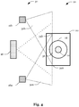
- Fig. 4 also shows a modification of the in Fig. 3a embodiment shown, but which also apply to the in Figure 3b The embodiment shown is transferable, the in Fig. 4 The modification shown is characterized in that the electromagnetic radiation moves along flat surfaces 32a, 32b is emitted and / or (instead of curved) can be focused on straight spatial curves 34a, 34b.
- the in Fig. 4 The modification shown, that the radiation sources 16a, 16b (as also in Fig. 6 and Fig. 8 illustrated) can be inclined towards the work area 28 (for example a workpiece section / area to be machined or a process point).
- the sensor unit 18 can be preceded by a mirror arrangement 38 which enables the workpiece 14 or the reflection track 36 to be detected from different perspectives.
- the sensor unit 18 can, for example, be divided into several detection areas, each detection area serving to detect the workpiece 14 or the reflection track 36 from one perspective (for example a central and two side views).
- several sensor units 18 can also be provided, which detect the workpiece 14 or the reflection track 36 from different perspectives.
- the perspectives can correspond to viewing locations which are spaced apart from one another parallel to the reflection track 36 in order to be able to compensate for shading caused by the geometry of the workpiece 14.
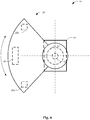
- the measuring unit 30 In order to be able to align the measuring unit 30 in the machining direction (feed direction), as in FIG Fig. 6 as a modification of the in Fig. 1a illustrated device, the measuring unit 30 about an axis, which, for example, runs through the machining unit 12 or a tool of the machining unit 12) can be pivoted.
- the processing unit 12 can be moved in an area (2 or 3-dimensional) extending opposite the workpiece support 20, the axis running perpendicular to the workpiece support or perpendicular to a surface of the workpiece 14.
- the radiation sources 16a, 16b (as also in Fig. 4 illustrated) towards the work area 28 (for example a workpiece section / area to be machined or a process point).
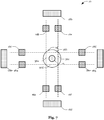
- the device 10 can be provided with a plurality of measuring units 30 instead of a single measuring unit 30.
- the measuring units 30 can generate a beam curtain enveloping the processing unit 12 (in the circumferential direction) (from intersecting beam paths) through which intersecting beam paths
- Reflection tracks 36 are generated.
- One or more measuring units 30 can also be arranged in their own housing (for example a housing which is designed for protection class IP 61) and can be integrated as a module in a processing machine.
- the housing can furthermore comprise a cooling device for cooling the housing interior or the measuring unit (s) 30.
- the power and data can also be supplied via an Ethernet connection.
- a separate power supply connection can be provided.
- the housing can have openings for emitting the electromagnetic radiation and for capturing the reflected electromagnetic radiation. The openings can be provided with exchangeable protective glasses.
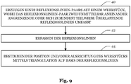
- Fig. 9 shows a flowchart of a method for determining a position and / or orientation of the workpiece 14.
- the method begins with a step 40 of generating a pair of reflection lines on the workpiece 16, the pair of reflection lines having two reflection lines directly adjacent or at least partially overlapping includes.
- the position and / or orientation of the workpiece 14 is determined in step 44 by means of triangulation on the basis of the reflection lines.
Landscapes
- Physics & Mathematics (AREA)
- Engineering & Computer Science (AREA)
- Mechanical Engineering (AREA)
- Optics & Photonics (AREA)
- General Physics & Mathematics (AREA)
- Machine Tool Sensing Apparatuses (AREA)
- Length Measuring Devices By Optical Means (AREA)
Claims (10)
- Dispositif (10) pour déterminer une position et/ou une orientation d'une pièce (14) par rapport à une unité d'usinage (12), comprenant :une première source de rayonnement (16) disposée dans une relation de position définie par rapport à l'unité d'usinage (12) ou dans une relation de position définie par rapport à un logement qui est prévu pour recevoir l'unité d'usinage (12) ;une seconde source de rayonnement (16) ou une unité de séparateur de faisceau (22) disposée à distance de la première source de rayonnement (16) dans une direction spatiale ;dans lequel les sources de rayonnement (16) ou l'unité de séparateur de faisceau (22) sont configurées pour focaliser le rayonnement électromagnétique sur deux courbes spatiales (34) directement adjacentes ou se chevauchant au moins partiellement ou pour rayonner le rayonnement électromagnétique le long de deux surfaces (32) directement adjacentes ou se coupant pendant le fonctionnement du dispositif (10) ;une unité de capteur disposée selon une relation de position définie par rapport aux sources de rayonnement (16) ou l'unité de séparation de faisceau (22), laquelle est configurée pour détecter le rayonnement électromagnétique rayonné par la première source de rayonnement (16) ou les sources de rayonnement (16) et réfléchi sur une surface de la pièce (14) et/ou le rayonnement électromagnétique rayonné par la surface de la pièce (14) pendant le fonctionnement du dispositif (10) ; etune unité de traitement, laquelle est configurée pour déterminer la position et/ou l'orientation de la pièce (14) par rapport à l'unité d'usinage (12) sur la base du rayonnement électromagnétique détecté ;caractérisé en ce quel'unité de traitement est configurée pour émettre un signal d'erreur si une distance entre une première piste de réflexion (36) du rayonnement électromagnétique sur une surface et une seconde piste de réflexion (36) du rayonnement électromagnétique sur la surface se situe hors d'une plage de tolérance.
- Dispositif (10) selon la revendication 1, dans lequel les courbes spatiales (34) se situent dans un plan ou les surfaces (32) sont planes.
- Dispositif (10) selon la revendication 1 ou 2, dans lequel les courbes spatiales (34) sont droites.
- Dispositif (10) selon l'une quelconque des revendications 1 à 3, dans lequel l'unité de détection (18) comprend un agencement de miroir (38) qui s'étend le long des deux courbes spatiales (34) directement adjacentes ou se chevauchant au moins partiellement ou le long des deux surfaces (32) se coupant et permet une détection du rayonnement électromagnétique depuis différentes perspectives.
- Dispositif (10) selon l'une quelconque des revendications 1 à 4, dans lequel un capteur de l'unité de détection (18) est disposé sur une bissectrice d'une ligne de connexion entre la première source de rayonnement (16) et la seconde source de rayonnement (16) et/ou l'unité de détection (18) remplit la condition de Scheimpflug.
- Dispositif (10) selon l'une quelconque des revendications 1 à 5, dans lequel le dispositif (10) présente une unité de mesure (30) comprenant la première source de rayonnement (16), la seconde source de rayonnement (16) ou l'unité de séparateur de faisceau (22) et l'unité de capteur (18), dans lequel l'unité de mesure (30) est montée de manière rotative dans le dispositif (10) autour d'un axe de rotation.
- Dispositif (10) selon l'une quelconque des revendications 1 à 6, dans lequel la première source de rayonnement (16), la seconde source de rayonnement (16) ou l'unité de séparateur de faisceau (22) et l'unité de détection (18) sont comprises dans une unité de mesure (30) et le dispositif (10) présente une pluralité de telles unités de mesure (30).
- Dispositif (10) selon la revendication 7, dans lequel les trajets de faisceau 26 des unités de mesure (30) se coupent.
- Procédé pour déterminer une position et/ou une orientation d'une pièce (14), comprenant :la génération (40) d'une ou de plusieurs paires de lignes de réflexion, dans lequel chaque paire de lignes de réflexion comprend deux lignes de réflexion directement adjacentes ou se chevauchant au moins partiellement, et/ou parallèles, de préférence des lignes lumineuses, qui sont générées par un rayonnement électromagnétique rayonné sur la surface depuis différentes directions ;la détection (42) des lignes de réflexion ; etla détermination (44) de la position et/ou de l'orientation de la pièce (14) par triangulation sur la base des lignes de réflexion ;caractérisé en ce que le procédé comprend en outreune détermination d'une distance entre les lignes de réflexion d'une paire de lignes de réflexion et l'émission d'un signal d'erreur si la distance se situe hors d'une plage de tolérance.
- Procédé selon la revendication 9, dans lequel des lignes de réflexion de différentes paires de lignes de réflexion se coupent à la surface de la pièce (14) et/ou renferment des angles de même taille.
Applications Claiming Priority (2)
| Application Number | Priority Date | Filing Date | Title |
|---|---|---|---|
| DE102017126786.7A DE102017126786A1 (de) | 2017-11-14 | 2017-11-14 | Vorrichtung und Verfahren zum Bestimmen einer Position und/oder Ausrichtung eines Werkstücks |
| PCT/EP2018/080035 WO2019096595A1 (fr) | 2017-11-14 | 2018-11-02 | Dispositif et procédé pour déterminer la position et/ou l'orientation d'une pièce |
Publications (2)
| Publication Number | Publication Date |
|---|---|
| EP3710199A1 EP3710199A1 (fr) | 2020-09-23 |
| EP3710199B1 true EP3710199B1 (fr) | 2021-10-13 |
Family
ID=64172479
Family Applications (1)
| Application Number | Title | Priority Date | Filing Date |
|---|---|---|---|
| EP18799485.0A Active EP3710199B1 (fr) | 2017-11-14 | 2018-11-02 | Dispositif et procédé pour déterminer la position et/ou l'orientation d'une pièce |
Country Status (3)
| Country | Link |
|---|---|
| EP (1) | EP3710199B1 (fr) |
| DE (1) | DE102017126786A1 (fr) |
| WO (1) | WO2019096595A1 (fr) |
Families Citing this family (4)
| Publication number | Priority date | Publication date | Assignee | Title |
|---|---|---|---|---|
| DE102020101172A1 (de) * | 2020-01-20 | 2021-07-22 | Homag Gmbh | Vorrichtung und Verfahren zum Bearbeiten eines Werkstücks |
| US11996308B2 (en) * | 2021-03-03 | 2024-05-28 | Taiwan Semiconductor Manufacturing Company, Ltd. | Method for mapping wafers in a wafer carrier |
| DE102022101379B4 (de) | 2022-01-21 | 2023-08-24 | Precitec Gmbh & Co. Kg | Laserbearbeitungskopf und laserbearbeitungssystem mit entsprechendem laserbearbeitungskopf |
| DE102022125219B3 (de) | 2022-09-29 | 2024-02-08 | Schwind Eye-Tech-Solutions Gmbh | Bearbeitungsvorrichtung zum Bearbeiten eines Bearbeitungsobjekts, Verfahren, Computerprogramm sowie computerlesbares Medium |
Family Cites Families (8)
| Publication number | Priority date | Publication date | Assignee | Title |
|---|---|---|---|---|
| DE4301538A1 (de) * | 1992-03-17 | 1994-07-28 | Peter Dr Ing Brueckner | Verfahren und Anordnung zur berührungslosen dreidimensionalen Messung, insbesondere zur Messung von Gebißmodellen |
| DE10335685A1 (de) * | 2002-08-02 | 2004-03-18 | Kappner, Helmut A. | Vorrichtung zum umseitigen Prüfen von Werkstücken |
| US7009717B2 (en) * | 2002-08-14 | 2006-03-07 | Metris N.V. | Optical probe for scanning the features of an object and methods therefor |
| DE102007031835B4 (de) * | 2007-07-07 | 2009-04-09 | Lensation Gmbh | Optische Führung und online Kontrolle an einem Werkzeug |
| US20090020688A1 (en) * | 2007-07-20 | 2009-01-22 | Christopher Scott Lovchik | Workpiece sensor |
| FR2925376B1 (fr) * | 2007-12-19 | 2010-04-30 | Ct Tech Des Ind Mecaniques | Appareil pour positionner un outil par rapport a une piece a traiter |
| DE102011104550B4 (de) * | 2011-06-17 | 2014-04-30 | Precitec Kg | Optische Messvorrichtung zur Überwachung einer Fügenaht, Fügekopf und Laserschweißkopf mit der selben |
| DE102012101301B4 (de) * | 2012-02-17 | 2014-11-06 | Kocos Automation Gmbh | Vorrichtung zur berührungslosen Kantenprofilbestimmung an einem dünnen scheibenförmigen Objekt |
-
2017
- 2017-11-14 DE DE102017126786.7A patent/DE102017126786A1/de not_active Withdrawn
-
2018
- 2018-11-02 EP EP18799485.0A patent/EP3710199B1/fr active Active
- 2018-11-02 WO PCT/EP2018/080035 patent/WO2019096595A1/fr not_active Ceased
Also Published As
| Publication number | Publication date |
|---|---|
| EP3710199A1 (fr) | 2020-09-23 |
| DE102017126786A1 (de) | 2019-05-16 |
| WO2019096595A1 (fr) | 2019-05-23 |
Similar Documents
| Publication | Publication Date | Title |
|---|---|---|
| EP3710199B1 (fr) | Dispositif et procédé pour déterminer la position et/ou l'orientation d'une pièce | |
| DE102018002960B4 (de) | Laserbearbeitungssystem mit messfunktion | |
| EP2544849B1 (fr) | Tête de travail au laser et procédé de travail au laser | |
| DE102005022095B4 (de) | Verfahren und Vorrichtung zur Bestimmung einer lateralen Relativbewegung zwischen einem Bearbeitungskopf und einem Werkstück | |
| DE69127121T3 (de) | Vorrichtung und Verfahren zum automatischen Ausrichten einer Schweissvorrichtung zum Stumpfschweissen von Werkstücken | |
| DE102012100721B3 (de) | Verfahren zum Regeln eines Laserschneidprozesses und Laserschneidmaschine | |
| DE10297255B4 (de) | Verfahren und Vorrichtung zum Überwachen und Einstellen eines Laserschweißprozesses | |
| DE102015216858B4 (de) | Laserbearbeitungsvorrichtung | |
| DE19963010B4 (de) | Verfahren und Vorrichtung zur Laserbearbeitung von Werkstücken | |
| CH704157B1 (de) | Schweisskopf und Verfahren zum Fügen eines Werkstücks. | |
| DE102004039410A1 (de) | Verfahren und Vorrichtung zur Regelung eines automatischen Bearbeitungsprozesses | |
| EP2242623B1 (fr) | Procédé et dispositif d'assemblage | |
| DE102013022085A1 (de) | Verfahren und Vorrichtung zur Überwachung und Regelung der Bearbeitungsbahn bei einem Laser-Fügeprozess | |
| EP2418040B1 (fr) | Procédé de contrôle d'un dispositif de soudure par laser | |
| WO2010088873A1 (fr) | Dispositif comportant une optique de balayage pour le traitement de matériaux au laser | |
| DE102015224575A1 (de) | Laserbearbeitungsvorrichtung | |
| DE102021103206A1 (de) | Verfahren zum Optimieren einer Bearbeitungszeit eines Laserbearbeitungsprozesses, Verfahren zum Durchführen eines Laserbearbeitungsprozesses an einem Werkstück und Laserbearbeitungssystem, welches eingerichtet ist, um diese durchzuführen | |
| WO2020078912A1 (fr) | Procédé de détermination d'une position corrigée de tête d'usinage et machine d'usinage | |
| WO2008046408A2 (fr) | Procédé et dispositif pour le positionnement fin d'un outil avec un organe de manipulation | |
| DE102013212652A1 (de) | Vorrichtung zum Betreiben einer Werkzeugmaschine und Werkzeugmaschine | |
| EP2874778A1 (fr) | Procédé et dispositif de mesure de distance sans contact | |
| DE102014002183B4 (de) | Einrichtung zur kontrollierten Laserbearbeitung wenigstens eines Werkstücks | |
| DE102005038587A1 (de) | Messsystem und Verfahren zum Vermessen eines Laserstrahls | |
| DE102016222681B4 (de) | Verfahren und System zum Vorbereiten einer Bearbeitung von mindestens zwei Bauteilen | |
| DE4321666A1 (de) | Einrichtung zur Messung von Oberflächenstrukturen von Mustern |
Legal Events
| Date | Code | Title | Description |
|---|---|---|---|
| STAA | Information on the status of an ep patent application or granted ep patent |
Free format text: STATUS: UNKNOWN |
|
| STAA | Information on the status of an ep patent application or granted ep patent |
Free format text: STATUS: THE INTERNATIONAL PUBLICATION HAS BEEN MADE |
|
| PUAI | Public reference made under article 153(3) epc to a published international application that has entered the european phase |
Free format text: ORIGINAL CODE: 0009012 |
|
| STAA | Information on the status of an ep patent application or granted ep patent |
Free format text: STATUS: REQUEST FOR EXAMINATION WAS MADE |
|
| 17P | Request for examination filed |
Effective date: 20200527 |
|
| AK | Designated contracting states |
Kind code of ref document: A1 Designated state(s): AL AT BE BG CH CY CZ DE DK EE ES FI FR GB GR HR HU IE IS IT LI LT LU LV MC MK MT NL NO PL PT RO RS SE SI SK SM TR |
|
| AX | Request for extension of the european patent |
Extension state: BA ME |
|
| DAV | Request for validation of the european patent (deleted) | ||
| DAX | Request for extension of the european patent (deleted) | ||
| GRAP | Despatch of communication of intention to grant a patent |
Free format text: ORIGINAL CODE: EPIDOSNIGR1 |
|
| STAA | Information on the status of an ep patent application or granted ep patent |
Free format text: STATUS: GRANT OF PATENT IS INTENDED |
|
| RIC1 | Information provided on ipc code assigned before grant |
Ipc: B23Q 17/24 20060101AFI20210601BHEP Ipc: G01B 11/02 20060101ALI20210601BHEP Ipc: G01B 11/00 20060101ALI20210601BHEP Ipc: B23Q 17/22 20060101ALI20210601BHEP |
|
| INTG | Intention to grant announced |
Effective date: 20210630 |
|
| GRAS | Grant fee paid |
Free format text: ORIGINAL CODE: EPIDOSNIGR3 |
|
| GRAA | (expected) grant |
Free format text: ORIGINAL CODE: 0009210 |
|
| STAA | Information on the status of an ep patent application or granted ep patent |
Free format text: STATUS: THE PATENT HAS BEEN GRANTED |
|
| AK | Designated contracting states |
Kind code of ref document: B1 Designated state(s): AL AT BE BG CH CY CZ DE DK EE ES FI FR GB GR HR HU IE IS IT LI LT LU LV MC MK MT NL NO PL PT RO RS SE SI SK SM TR |
|
| REG | Reference to a national code |
Ref country code: GB Ref legal event code: FG4D Free format text: NOT ENGLISH |
|
| REG | Reference to a national code |
Ref country code: CH Ref legal event code: EP |
|
| REG | Reference to a national code |
Ref country code: DE Ref legal event code: R096 Ref document number: 502018007460 Country of ref document: DE |
|
| REG | Reference to a national code |
Ref country code: IE Ref legal event code: FG4D Free format text: LANGUAGE OF EP DOCUMENT: GERMAN |
|
| REG | Reference to a national code |
Ref country code: AT Ref legal event code: REF Ref document number: 1437838 Country of ref document: AT Kind code of ref document: T Effective date: 20211115 |
|
| REG | Reference to a national code |
Ref country code: LT Ref legal event code: MG9D |
|
| REG | Reference to a national code |
Ref country code: NL Ref legal event code: MP Effective date: 20211013 |
|
| RAP4 | Party data changed (patent owner data changed or rights of a patent transferred) |
Owner name: FRAUNHOFER-GESELLSCHAFT ZUR FOERDERUNG DER ANGEWANDTEN FORSCHUNG E.V. |
|
| PG25 | Lapsed in a contracting state [announced via postgrant information from national office to epo] |
Ref country code: RS Free format text: LAPSE BECAUSE OF FAILURE TO SUBMIT A TRANSLATION OF THE DESCRIPTION OR TO PAY THE FEE WITHIN THE PRESCRIBED TIME-LIMIT Effective date: 20211013 Ref country code: LT Free format text: LAPSE BECAUSE OF FAILURE TO SUBMIT A TRANSLATION OF THE DESCRIPTION OR TO PAY THE FEE WITHIN THE PRESCRIBED TIME-LIMIT Effective date: 20211013 Ref country code: FI Free format text: LAPSE BECAUSE OF FAILURE TO SUBMIT A TRANSLATION OF THE DESCRIPTION OR TO PAY THE FEE WITHIN THE PRESCRIBED TIME-LIMIT Effective date: 20211013 Ref country code: BG Free format text: LAPSE BECAUSE OF FAILURE TO SUBMIT A TRANSLATION OF THE DESCRIPTION OR TO PAY THE FEE WITHIN THE PRESCRIBED TIME-LIMIT Effective date: 20220113 |
|
| PG25 | Lapsed in a contracting state [announced via postgrant information from national office to epo] |
Ref country code: IS Free format text: LAPSE BECAUSE OF FAILURE TO SUBMIT A TRANSLATION OF THE DESCRIPTION OR TO PAY THE FEE WITHIN THE PRESCRIBED TIME-LIMIT Effective date: 20220213 Ref country code: HR Free format text: LAPSE BECAUSE OF FAILURE TO SUBMIT A TRANSLATION OF THE DESCRIPTION OR TO PAY THE FEE WITHIN THE PRESCRIBED TIME-LIMIT Effective date: 20211013 Ref country code: GR Free format text: LAPSE BECAUSE OF FAILURE TO SUBMIT A TRANSLATION OF THE DESCRIPTION OR TO PAY THE FEE WITHIN THE PRESCRIBED TIME-LIMIT Effective date: 20220114 Ref country code: ES Free format text: LAPSE BECAUSE OF FAILURE TO SUBMIT A TRANSLATION OF THE DESCRIPTION OR TO PAY THE FEE WITHIN THE PRESCRIBED TIME-LIMIT Effective date: 20211013 Ref country code: SE Free format text: LAPSE BECAUSE OF FAILURE TO SUBMIT A TRANSLATION OF THE DESCRIPTION OR TO PAY THE FEE WITHIN THE PRESCRIBED TIME-LIMIT Effective date: 20211013 Ref country code: PT Free format text: LAPSE BECAUSE OF FAILURE TO SUBMIT A TRANSLATION OF THE DESCRIPTION OR TO PAY THE FEE WITHIN THE PRESCRIBED TIME-LIMIT Effective date: 20220214 Ref country code: PL Free format text: LAPSE BECAUSE OF FAILURE TO SUBMIT A TRANSLATION OF THE DESCRIPTION OR TO PAY THE FEE WITHIN THE PRESCRIBED TIME-LIMIT Effective date: 20211013 Ref country code: NO Free format text: LAPSE BECAUSE OF FAILURE TO SUBMIT A TRANSLATION OF THE DESCRIPTION OR TO PAY THE FEE WITHIN THE PRESCRIBED TIME-LIMIT Effective date: 20220113 Ref country code: NL Free format text: LAPSE BECAUSE OF FAILURE TO SUBMIT A TRANSLATION OF THE DESCRIPTION OR TO PAY THE FEE WITHIN THE PRESCRIBED TIME-LIMIT Effective date: 20211013 Ref country code: LV Free format text: LAPSE BECAUSE OF FAILURE TO SUBMIT A TRANSLATION OF THE DESCRIPTION OR TO PAY THE FEE WITHIN THE PRESCRIBED TIME-LIMIT Effective date: 20211013 |
|
| REG | Reference to a national code |
Ref country code: DE Ref legal event code: R097 Ref document number: 502018007460 Country of ref document: DE |
|
| REG | Reference to a national code |
Ref country code: CH Ref legal event code: PL |
|
| PG25 | Lapsed in a contracting state [announced via postgrant information from national office to epo] |
Ref country code: SM Free format text: LAPSE BECAUSE OF FAILURE TO SUBMIT A TRANSLATION OF THE DESCRIPTION OR TO PAY THE FEE WITHIN THE PRESCRIBED TIME-LIMIT Effective date: 20211013 Ref country code: SK Free format text: LAPSE BECAUSE OF FAILURE TO SUBMIT A TRANSLATION OF THE DESCRIPTION OR TO PAY THE FEE WITHIN THE PRESCRIBED TIME-LIMIT Effective date: 20211013 Ref country code: RO Free format text: LAPSE BECAUSE OF FAILURE TO SUBMIT A TRANSLATION OF THE DESCRIPTION OR TO PAY THE FEE WITHIN THE PRESCRIBED TIME-LIMIT Effective date: 20211013 Ref country code: MC Free format text: LAPSE BECAUSE OF FAILURE TO SUBMIT A TRANSLATION OF THE DESCRIPTION OR TO PAY THE FEE WITHIN THE PRESCRIBED TIME-LIMIT Effective date: 20211013 Ref country code: LU Free format text: LAPSE BECAUSE OF NON-PAYMENT OF DUE FEES Effective date: 20211102 Ref country code: EE Free format text: LAPSE BECAUSE OF FAILURE TO SUBMIT A TRANSLATION OF THE DESCRIPTION OR TO PAY THE FEE WITHIN THE PRESCRIBED TIME-LIMIT Effective date: 20211013 Ref country code: DK Free format text: LAPSE BECAUSE OF FAILURE TO SUBMIT A TRANSLATION OF THE DESCRIPTION OR TO PAY THE FEE WITHIN THE PRESCRIBED TIME-LIMIT Effective date: 20211013 Ref country code: CZ Free format text: LAPSE BECAUSE OF FAILURE TO SUBMIT A TRANSLATION OF THE DESCRIPTION OR TO PAY THE FEE WITHIN THE PRESCRIBED TIME-LIMIT Effective date: 20211013 Ref country code: BE Free format text: LAPSE BECAUSE OF NON-PAYMENT OF DUE FEES Effective date: 20211130 |
|
| REG | Reference to a national code |
Ref country code: BE Ref legal event code: MM Effective date: 20211130 |
|
| PLBE | No opposition filed within time limit |
Free format text: ORIGINAL CODE: 0009261 |
|
| STAA | Information on the status of an ep patent application or granted ep patent |
Free format text: STATUS: NO OPPOSITION FILED WITHIN TIME LIMIT |
|
| 26N | No opposition filed |
Effective date: 20220714 |
|
| PG25 | Lapsed in a contracting state [announced via postgrant information from national office to epo] |
Ref country code: IE Free format text: LAPSE BECAUSE OF NON-PAYMENT OF DUE FEES Effective date: 20211102 Ref country code: AL Free format text: LAPSE BECAUSE OF FAILURE TO SUBMIT A TRANSLATION OF THE DESCRIPTION OR TO PAY THE FEE WITHIN THE PRESCRIBED TIME-LIMIT Effective date: 20211013 |
|
| PG25 | Lapsed in a contracting state [announced via postgrant information from national office to epo] |
Ref country code: SI Free format text: LAPSE BECAUSE OF FAILURE TO SUBMIT A TRANSLATION OF THE DESCRIPTION OR TO PAY THE FEE WITHIN THE PRESCRIBED TIME-LIMIT Effective date: 20211013 |
|
| PG25 | Lapsed in a contracting state [announced via postgrant information from national office to epo] |
Ref country code: IT Free format text: LAPSE BECAUSE OF FAILURE TO SUBMIT A TRANSLATION OF THE DESCRIPTION OR TO PAY THE FEE WITHIN THE PRESCRIBED TIME-LIMIT Effective date: 20211013 |
|
| P01 | Opt-out of the competence of the unified patent court (upc) registered |
Effective date: 20230524 |
|
| PG25 | Lapsed in a contracting state [announced via postgrant information from national office to epo] |
Ref country code: CY Free format text: LAPSE BECAUSE OF FAILURE TO SUBMIT A TRANSLATION OF THE DESCRIPTION OR TO PAY THE FEE WITHIN THE PRESCRIBED TIME-LIMIT Effective date: 20211013 |
|
| PG25 | Lapsed in a contracting state [announced via postgrant information from national office to epo] |
Ref country code: LI Free format text: LAPSE BECAUSE OF NON-PAYMENT OF DUE FEES Effective date: 20220701 Ref country code: HU Free format text: LAPSE BECAUSE OF FAILURE TO SUBMIT A TRANSLATION OF THE DESCRIPTION OR TO PAY THE FEE WITHIN THE PRESCRIBED TIME-LIMIT; INVALID AB INITIO Effective date: 20181102 Ref country code: CH Free format text: LAPSE BECAUSE OF NON-PAYMENT OF DUE FEES Effective date: 20220701 |
|
| PG25 | Lapsed in a contracting state [announced via postgrant information from national office to epo] |
Ref country code: MK Free format text: LAPSE BECAUSE OF FAILURE TO SUBMIT A TRANSLATION OF THE DESCRIPTION OR TO PAY THE FEE WITHIN THE PRESCRIBED TIME-LIMIT Effective date: 20211013 |
|
| PG25 | Lapsed in a contracting state [announced via postgrant information from national office to epo] |
Ref country code: MT Free format text: LAPSE BECAUSE OF FAILURE TO SUBMIT A TRANSLATION OF THE DESCRIPTION OR TO PAY THE FEE WITHIN THE PRESCRIBED TIME-LIMIT Effective date: 20211013 |
|
| PGFP | Annual fee paid to national office [announced via postgrant information from national office to epo] |
Ref country code: DE Payment date: 20241119 Year of fee payment: 7 |
|
| REG | Reference to a national code |
Ref country code: AT Ref legal event code: MM01 Ref document number: 1437838 Country of ref document: AT Kind code of ref document: T Effective date: 20231102 |
|
| PGFP | Annual fee paid to national office [announced via postgrant information from national office to epo] |
Ref country code: GB Payment date: 20241121 Year of fee payment: 7 |
|
| PGFP | Annual fee paid to national office [announced via postgrant information from national office to epo] |
Ref country code: FR Payment date: 20241121 Year of fee payment: 7 |
|
| PG25 | Lapsed in a contracting state [announced via postgrant information from national office to epo] |
Ref country code: AT Free format text: LAPSE BECAUSE OF NON-PAYMENT OF DUE FEES Effective date: 20231102 |
|
| PG25 | Lapsed in a contracting state [announced via postgrant information from national office to epo] |
Ref country code: AT Free format text: LAPSE BECAUSE OF NON-PAYMENT OF DUE FEES Effective date: 20231102 |
|
| PG25 | Lapsed in a contracting state [announced via postgrant information from national office to epo] |
Ref country code: TR Free format text: LAPSE BECAUSE OF FAILURE TO SUBMIT A TRANSLATION OF THE DESCRIPTION OR TO PAY THE FEE WITHIN THE PRESCRIBED TIME-LIMIT Effective date: 20211013 |
|
| PGFP | Annual fee paid to national office [announced via postgrant information from national office to epo] |
Ref country code: AT Payment date: 20260410 Year of fee payment: 5 |