EP3710294B1 - Dichtungsstrang mit thermoplast-kernteil - Google Patents
Dichtungsstrang mit thermoplast-kernteil Download PDFInfo
- Publication number
- EP3710294B1 EP3710294B1 EP18826499.8A EP18826499A EP3710294B1 EP 3710294 B1 EP3710294 B1 EP 3710294B1 EP 18826499 A EP18826499 A EP 18826499A EP 3710294 B1 EP3710294 B1 EP 3710294B1
- Authority
- EP
- European Patent Office
- Prior art keywords
- core part
- sealing
- rest
- extruded
- extrusion
- Prior art date
- Legal status (The legal status is an assumption and is not a legal conclusion. Google has not performed a legal analysis and makes no representation as to the accuracy of the status listed.)
- Active
Links
Images

Classifications
-
- B—PERFORMING OPERATIONS; TRANSPORTING
- B60—VEHICLES IN GENERAL
- B60J—WINDOWS, WINDSCREENS, NON-FIXED ROOFS, DOORS, OR SIMILAR DEVICES FOR VEHICLES; REMOVABLE EXTERNAL PROTECTIVE COVERINGS SPECIALLY ADAPTED FOR VEHICLES
- B60J10/00—Sealing arrangements
- B60J10/15—Sealing arrangements characterised by the material
- B60J10/16—Sealing arrangements characterised by the material consisting of two or more plastic materials having different physical or chemical properties
-
- B—PERFORMING OPERATIONS; TRANSPORTING
- B29—WORKING OF PLASTICS; WORKING OF SUBSTANCES IN A PLASTIC STATE IN GENERAL
- B29C—SHAPING OR JOINING OF PLASTICS; SHAPING OF MATERIAL IN A PLASTIC STATE, NOT OTHERWISE PROVIDED FOR; AFTER-TREATMENT OF THE SHAPED PRODUCTS, e.g. REPAIRING
- B29C48/00—Extrusion moulding, i.e. expressing the moulding material through a die or nozzle which imparts the desired form; Apparatus therefor
- B29C48/25—Component parts, details or accessories; Auxiliary operations
- B29C48/30—Extrusion nozzles or dies
- B29C48/32—Extrusion nozzles or dies with annular openings, e.g. for forming tubular articles
- B29C48/34—Cross-head annular extrusion nozzles, i.e. for simultaneously receiving moulding material and the preform to be coated
-
- B—PERFORMING OPERATIONS; TRANSPORTING
- B60—VEHICLES IN GENERAL
- B60J—WINDOWS, WINDSCREENS, NON-FIXED ROOFS, DOORS, OR SIMILAR DEVICES FOR VEHICLES; REMOVABLE EXTERNAL PROTECTIVE COVERINGS SPECIALLY ADAPTED FOR VEHICLES
- B60J10/00—Sealing arrangements
- B60J10/70—Sealing arrangements specially adapted for windows or windscreens
- B60J10/74—Sealing arrangements specially adapted for windows or windscreens for sliding window panes, e.g. sash guides
- B60J10/75—Sealing arrangements specially adapted for windows or windscreens for sliding window panes, e.g. sash guides for sealing the lower part of the panes
-
- B—PERFORMING OPERATIONS; TRANSPORTING
- B29—WORKING OF PLASTICS; WORKING OF SUBSTANCES IN A PLASTIC STATE IN GENERAL
- B29C—SHAPING OR JOINING OF PLASTICS; SHAPING OF MATERIAL IN A PLASTIC STATE, NOT OTHERWISE PROVIDED FOR; AFTER-TREATMENT OF THE SHAPED PRODUCTS, e.g. REPAIRING
- B29C48/00—Extrusion moulding, i.e. expressing the moulding material through a die or nozzle which imparts the desired form; Apparatus therefor
- B29C48/03—Extrusion moulding, i.e. expressing the moulding material through a die or nozzle which imparts the desired form; Apparatus therefor characterised by the shape of the extruded material at extrusion
- B29C48/12—Articles with an irregular circumference when viewed in cross-section, e.g. window profiles
-
- B—PERFORMING OPERATIONS; TRANSPORTING
- B29—WORKING OF PLASTICS; WORKING OF SUBSTANCES IN A PLASTIC STATE IN GENERAL
- B29C—SHAPING OR JOINING OF PLASTICS; SHAPING OF MATERIAL IN A PLASTIC STATE, NOT OTHERWISE PROVIDED FOR; AFTER-TREATMENT OF THE SHAPED PRODUCTS, e.g. REPAIRING
- B29C48/00—Extrusion moulding, i.e. expressing the moulding material through a die or nozzle which imparts the desired form; Apparatus therefor
- B29C48/15—Extrusion moulding, i.e. expressing the moulding material through a die or nozzle which imparts the desired form; Apparatus therefor incorporating preformed parts or layers, e.g. extrusion moulding around inserts
- B29C48/154—Coating solid articles, i.e. non-hollow articles
- B29C48/155—Partial coating thereof
-
- B—PERFORMING OPERATIONS; TRANSPORTING
- B29—WORKING OF PLASTICS; WORKING OF SUBSTANCES IN A PLASTIC STATE IN GENERAL
- B29L—INDEXING SCHEME ASSOCIATED WITH SUBCLASS B29C, RELATING TO PARTICULAR ARTICLES
- B29L2031/00—Other particular articles
- B29L2031/001—Profiled members, e.g. beams, sections
- B29L2031/003—Profiled members, e.g. beams, sections having a profiled transverse cross-section
- B29L2031/005—Profiled members, e.g. beams, sections having a profiled transverse cross-section for making window frames
- B29L2031/006—Profiled members, e.g. beams, sections having a profiled transverse cross-section for making window frames and provided with a sealing element
-
- B—PERFORMING OPERATIONS; TRANSPORTING
- B29—WORKING OF PLASTICS; WORKING OF SUBSTANCES IN A PLASTIC STATE IN GENERAL
- B29L—INDEXING SCHEME ASSOCIATED WITH SUBCLASS B29C, RELATING TO PARTICULAR ARTICLES
- B29L2031/00—Other particular articles
- B29L2031/30—Vehicles, e.g. ships or aircraft, or body parts thereof
- B29L2031/3055—Cars
Definitions
- the invention relates to a sealing strip for forming a seal on a vehicle body, in particular a manhole strip or window guide for sealing a movable vehicle window pane, with a core part made of thermoplastic material and a sealing section made of elastomer material connected to the core part.
- the invention also relates to a method for producing such a sealing strip.
- Manhole strips comprising such a sealing strand are known through use, the V- or U-shaped core part of which is made of polypropylene (PP) and the lip-shaped sealing section of which is made of a thermoplastic elastomer (TPE).
- PP polypropylene
- TPE thermoplastic elastomer
- Such sealing strands are produced in a single extrusion step in which the sealing section is coextruded with the core part.
- a co-extruded sealing section made of a thermoplastic material-locking and / or form-locking elastomer does not require any subsequent vulcanization.
- JP 2003 181902 A JP 2000 108807 A and JP H05 77380 A various methods for a material or form-fitting connection of a vulcanized rubber seal with a thermoplastic material, for example a retaining element, are known.
- the invention creates a new sealing strip of the type mentioned at the outset, which is characterized in that the extruded sealing section consists of vulcanized elastomer material and that a core part section connected to the remaining core part is extruded onto the vulcanized sealing section with a material or / and form-fitting connection, where the Thermoplastic material of the remaining core part and the thermoplastic material of the core part section differ in a filler material.
- the sealing section is first extruded and, after its vulcanization, in the course of a separate extrusion of the core section, the sealing section is connected to the core part or core section in a material and / or form-fitting manner, the vulcanized sealing section being shrunk before the connection to the core part and the rest of the core part to the core section is extruded or injected on.
- the invention advantageously creates a sealing strip with a core part made of thermoplastic material, the sealing section of which consists of vulcanized elastomer material, preferably EPDM, so that it has an improved service life and sealing effect compared to sealing sections made of TPE. Since, according to the invention, the extrusion of the core part or core part section only takes place after the vulcanization of the sealing section, impairment of the core part or core part section due to the action of vulcanization heat is avoided.
- the degree of shrinkage is advantageously selected so that the remaining residual shrinkage of the sealing section is matched to the shrinkage of the core part after its extrusion. Impairments to the shape of the extruded composite part due to different shrinkage of its components are thus avoided.
- the core part section can consist of the same material as the rest of the core part, the thermoplastic material of the remaining core part and the thermoplastic material of the core part section differing, for example, only in the filler material.
- the remaining core part has a reinforcing glass fiber filling and the core part section has a talcum filling.
- the sealing section is connected to the core part or the core part section via a film coextruded with the sealing section.
- This film can advantageously be used to produce a permanent weld between the sealing section and the core part or the core part section during the extrusion of the core part, for example by ultrasonic welding. Because of the small thickness of the film, the heat supplied during vulcanization flows quickly into the material of the sealing section, so that the film made of thermoplastic material remains dimensionally stable during vulcanization.
- the film preferably consists of the same material as the rest of the core part or the core part section.
- the thickness of the film is preferably between 0.010 and 0.500 mm.
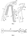
- Shaft strip shown in cross section for sealing a movable vehicle window pane at the entrance to a (not shown) window shaft comprises an extruded core section 2 made of a thermoplastic material, in the example shown made of glass fiber reinforced polypropylene (PP). Via the V-shaped or U-shaped core section 2, the duct strip can be slipped onto a body flange (not shown) adjoining the window duct.
- a thermoplastic material in the example shown made of glass fiber reinforced polypropylene (PP).
- Attachments 3 and 4 made of a thermoplastic elastomer (TPE) are connected to the core section 2.
- the approaches 3, 4 each have a groove 5 or 6 for receiving a bend 8 or 9 of a decorative strip 7, the decorative strip 7 being positively held in the grooves 5, 6 and the decorative strip 7 made of metal or plastic.
- the core sub-section 2 On one of the legs of the core sub-section 2 facing away from the decorative strip 7, the core sub-section 2 is connected to a sealing lip 10 made of vulcanized elastomer material, in the example shown EPDM. On its side facing the vehicle window pane 1, the sealing lip 10 has a flocking layer 11.
- the sealing lip 10 engages with a foot part 12 in a recess 13 in a core part section 14 which connects the core part section 2 to the sealing lip 10 and forms a shoulder.
- the core sub-section 14, like the core sub-section 2 in the example shown, consists of polypropylene (PP), but, in contrast to the core sub-section 2, does not contain any glass fiber reinforcement but a talc filling.
- a glass fiber thread 20 is embedded in the foot part 12.
- the extruded sealing lip 10 After vulcanization, the extruded sealing lip 10 is cooled and shrunk at 17, possibly during an interruption in the current strand production, before it is then fed to a second extrusion device 18, where it forms part of the mold wall of the extrusion tool.
- the extrusion of the core part 2 takes place with coextrusion of the attachments 3 and 4 as well as the core sub-section 14.
- the core sub-section 14 is connected to the sealing lip 10, with this connection being both a material bond between the core sub-section 14 and the sealing lip 10 as well as a form fit of the foot part 12 in the recess 13 contributes.
- the degree of shrinkage of the sealing lip 10 before it enters the second extrusion device 18 is such that the residual shrinkage of the sealing lip 10 corresponds to the total shrinkage of the extrudate 21 produced in the second extrusion device 18.
- the extrudate 21 can also only be the core part section 14, onto which the remaining core part, i.e. the core part section 2, is then extruded in a third extrusion step.
- the core sub-section 2 could also be injection-molded onto the core sub-section 14.
- FIG. 3 The embodiment shown of a manhole strip differs from the manhole strip from FIG Fig. 1 in that a connection between a core part 2a and a sealing lip 10a is established via a thin film 19.
- the film 19 consists of a thermoplastic material, preferably the thermoplastic material of the Core part 2a. In the example shown, its thickness is 0.020 mm.
- the film 19 is already coextruded in the course of the extrusion of the sealing lip 10a. Due to its small thickness, the heat supplied during the subsequent vulcanization flows quickly into the elastomeric material of the sealing lip that lies against it, so that the film 19 remains dimensionally stable during the vulcanization.
- the film 19 ensures that the sealing lip 10a is firmly welded to the core part 2a.
Landscapes
- Engineering & Computer Science (AREA)
- Mechanical Engineering (AREA)
- Manufacturing & Machinery (AREA)
- Seal Device For Vehicle (AREA)
- Extrusion Moulding Of Plastics Or The Like (AREA)
Description
- Die Erfindung betrifft einen Dichtungsstrang für die Bildung einer Dichtung an einer Fahrzeugkarosserie, insbesondere einer Schachtleiste oder Fensterführung zur Abdichtung einer bewegbaren Fahrzeugfensterscheibe, mit einem Kernteil aus Thermoplastmaterial und einem mit dem Kernteil verbundenen Dichtungsabschnitt aus Elastomermaterial.
- Die Erfindung betrifft ferner ein Verfahren zur Herstellung eines solchen Dichtungsstrangs.
- Durch Benutzung sind einen solchen Dichtungsstrang umfassende Schachtleisten bekannt, deren V- oder U-förmiger Kernteil aus Polypropylen (PP) und deren lippenförmiger Dichtungsabschnitt aus einem thermoplastischen Elastomer (TPE) besteht.
- Die Herstellung solcher Dichtungsstränge erfolgt in einem einzigen Extrusionsschritt, bei dem der Dichtungsabschnitt mit dem Kernteil mitextrudiert wird. Bekanntermaßen bedarf ein mitextrudierter Dichtungsabschnitt aus einem thermoplastischen stoff- oder/und formschlüssiger Elastomer keiner anschließenden Vulkanisierung.
- Aus
JP 2003 181902 A JP 2000 108807 A JP H05 77380 A - Durch die Erfindung wird ein neuer Dichtungsstrang der eingangs genannten Art geschaffen, der dadurch gekennzeichnet ist, dass der extrudierte Dichtungsabschnitt aus vulkanisiertem Elastomermaterial besteht und dass ein mit dem übrigen Kernteil verbundener Kernteilabschnitt unter stoff- oder/und formschlüssiger Anbindung an den vulkanisierten Dichtungsabschnitt anextrudiert ist, wobei sich das Thermoplastmaterial des übrigen Kernteils und das Thermoplastmaterial des Kernteilabschntits in einem Füllmaterial unterscheiden.
- Erfindungsgemäß wird zuerst der Dichtungsabschnitt extrudiert und nach dessen Vulkanisation im Zuge einer separaten Extrusion des Kernteilabschnitts der Dichtungsabschnitt stoff- und/oder formschlüssig mit dem Kernteil bzw. Kernteilabschnitt verbunden, wobei der vulkanisierte Dichtungsabschnitt vor der Verbindung mit dem Kernteil geschrumpft wird und der übrige Kernteil an den Kernteilabschnitt anextrudiert oder angespritzt wird.
- Vorteilhaft wird durch die Erfindung ein Dichtungsstrang mit einem Kernteil aus Thermoplastmaterial geschaffen, dessen Dichtungsabschnitt aus vulkanisiertem Elastomermaterial, vorzugsweise EPDM, besteht, so dass er eine gegenüber Dichtungsabschnitten aus TPE verbesserte Standzeit und Dichtwirkung aufweist. Indem erfindungsgemäß die Extrusion des Kernteils bzw. Kernteilabschnitts erst nach der Vulkanisation des Dichtungsabschnitts erfolgt, sind Beeinträchtigungen des Kernteils bzw. Kernteilabschnitts durch Einwirkung von Vulkanisationswärme vermieden. Vorteilhaft wird der Schrumpfungsgrad so gewählt wird, dass die noch verbleibende Restschrumpfung des Dichtungsabschnitts an die Schrumpfung des Kernteils nach dessen Extrusion angeglichen ist. Beeinträchtigungen der Form des extrudierten Verbundteils durch unterschiedliche Schrumpfung seiner Komponenten sind so vermieden.
- Der Kernteilabschnitt kann aus dem gleichen Material wie der übrige Kernteil bestehen, wobei sich das Thermoplastmaterial des übrigen Kernteils und das Thermoplastmaterial des Kernteilabschntits z.B. nur in dem Füllmaterial unterscheiden.
- In einer Ausführungsform der Erfindung weist der übrige Kernteil eine verstärkende Glasfaserfüllung und der Kernteilabschnitt eine Talkumfüllung auf.
- In einer besonders bevorzugten Ausführungsform der Erfindung ist der Dichtungsabschnitt mit dem Kernteil oder dem Kernteilabschnitt über eine mit dem Dichtungsabschnitt mitextrudierte Folie verbunden. Vorteilhaft lässt sich über diese Folie bei der Extrusion des Kernteils eine feste Verschweißung zwischen dem Dichtungsabschnitt und dem Kernteil bzw. dem Kernteilabschnitt herstellen, z.B. durch Ultraschallschweißen. Wegen der geringen Dicke der Folie fließt bei der Vulkanisation zugeführte Wärme schnell in das Material des Dichtungsabschnitts ab, so dass die Folie aus Thermoplastmaterial während der Vulkanisation formbeständig bleibt. Vorzugsweise besteht die Folie aus dem gleichen Material wie der übrige Kernteil oder der Kernteilabschnitt.
- Die Dicke der Folie liegt vorzugsweise zwischen 0,010 und 0,500 mm.
- Die Erfindung ist nachfolgend anhand von Ausführungsbeispielen und der beiliegenden, sich auf diese Ausführungsbeispiele beziehenden Zeichnungen weiter erläutert. Es zeigen:
- Fig. 1
- eine Schachtleiste zur Abdichtung einer Fahrzeugfensterscheibe, die einen erfindungsgemäßen Dichtungsstrang umfasst,
- Fig. 2
- eine die Herstellung des Dichtungsstrangs von
Fig. 1 erläuternde Darstellung, und - Fig. 3
- ein weiteres Ausführungsbeispiel für einen Dichtungsstrang nicht erfindungsgemäß.
- Eine in
Fig. 1 im Querschnitt dargestellte Schachtleiste zur Abdichtung einer bewegbaren Fahrzeugfensterscheibe am Eingang zu einem (nicht gezeigten) Fensterschacht umfasst einen extrudierten Kernteilabschnitt 2 aus einem Thermoplastmaterial, in dem gezeigten Beispiel aus glasfaserverstärktem Polypropylen (PP). Über den V- oder U-förmigen Kernteilabschnitt 2 ist die Schachtleiste auf einen an den Fensterschacht grenzenden Karosserieflansch (nicht gezeigt) aufsteckbar. - Mit dem Kernteilabschnitt 2 verbunden sind Ansätze 3 und 4 aus einem thermoplastischen Elastomer (TPE). Die Ansätze 3,4 weisen jeweils eine Rille 5 bzw. 6 für die Aufnahme einer Abwinklung 8 bzw. 9 einer Zierleiste 7 auf, wobei die Zierleiste 7 in den Rillen 5,6 formschlüssig gehalten ist und die Zierleiste 7 aus Metall oder Kunststoff besteht.
- An einem der Zierleiste 7 abgewandten Schenkel des Kernteilabschnitts 2 ist der Kernteilabschnitt 2 mit einer Dichtungslippe 10 aus vulkanisiertem Elastomermaterial, in dem gezeigten Beispiel EPDM, verbunden. Auf ihrer der Fahrzeugfensterscheibe 1 zugewandten Seite weist die Dichtungslippe 10 eine Beflockungsschicht 11 auf.
- In dem Beispiel von
Fig. 1 greift die Dichtungslippe 10 mit einem Fußteil 12 in eine Ausnehmung 13 in einem den Kernteilabschnitt 2 mit der Dichtungslippe 10 verbindenden, einen Ansatz bildenden Kernteilabschnitt 14 ein. Der Kernteilabschnitt 14 besteht wie der Kernteilabschnitt 2 in dem gezeigten Beispiel aus Polypropylen (PP), enthält im Unterschied zu dem Kernteilabschnitt 2 aber keine Glasfaserverstärkung sondern eine Talkumfüllung. In den Fußteil 12 ist ein Glasfaserfaden 20 eingebettet. - Bei der Herstellung der in
Fig. 1 gezeigten Schachtleiste wird mit Hilfe einer ersten Extrusionseinrichtung 15 zunächst nur die Dichtungslippe 10 aus EPDM-Material extrudiert und in einer nachgeschalteten Vulkanisationseinrichtung 16 einer Wärmebehandlung unterzogen. - Nach der Vulkanisation erfolgt bei 17, ggf. während einer Unterbrechung der laufenden Strangfertigung, eine Abkühlung und Schrumpfung der extrudierten Dichtungslippe 10, bevor diese dann einer zweiten Extrusionseinrichtung 18 zugeführt wird, wo sie einen Teil der Formwand des Extrusionswerkzeugs bildet.
- In der zweiten Extrusionseinrichtung 18 erfolgt die Extrusion des Kernteils 2 unter Mitextrusion der Ansätze 3 und 4 sowie des Kernteilabschnitts 14. Dabei kommt es zur Verbindung des Kernteilabschnitts 14 mit der Dichtungslippe 10, wobei zu dieser Verbindung sowohl ein Stoffschluss zwischen dem Kernteilabschnitt 14 und der Dichtungslippe 10 als auch ein Formschluss des Fußteils 12 in der Ausnehmung 13 beiträgt.
- Der Schrumpfungsgrad der Dichtungslippe 10 vor dem Eintritt in die zweite Extrusionseinrichtung 18 ist so bemessen, dass die Restschrumpfung der Dichtungslippe 10 mit der Gesamtschrumpfung des in der zweiten Extrusionseinrichtung 18 hergestellten Extrudats 21 übereinstimmt.
- Bei dem Extrudat 21 kann es sich auch nur um den Kernteilabschnitt 14 handeln, an den dann in einem dritten Extrusionsabschritt der übrige Kernteil, d.h. der Kernteilabschnitt 2, anextrudiert wird. Der Kernteilabschnitt 2 könnte an den Kernteilabschnitt 14 auch angespritzt werden.
- Ein in
Fig. 3 gezeigtes Ausführungsbeispiel einer Schachtleiste unterscheidet sich von der Schachtleiste vonFig. 1 dadurch, dass eine Verbindung zwischen einem Kernteil 2a und einer Dichtungslippe 10a über eine dünne Folie 19 hergestellt ist. Die Folie 19 besteht aus einem Thermoplastmaterial, vorzugsweise dem Thermoplastmaterial des Kernteils 2a. Ihre Dicke beträgt in dem gezeigten Beispiel 0,020 mm. - Die Folie 19 wird bereits im Zuge der Extrusion der Dichtungslippe 10a mitextrudiert. Aufgrund ihrer geringen Dicke fließt bei der anschließenden Vulkanisation zugeführte Wärme schnell in das Elastomermaterial der anliegenden Dichtungslippe ab, so dass die Folie 19 während der Vulkanisation formbeständig bleibt.
- Bei der Verbindung der Dichtungslippe 10a mit dem Kernteil 2a im zweiten Extrusionsschritt sorgt die Folie 19 für eine feste Verschweißung der Dichtungslippe 10a mit dem Kernteil 2a.
Claims (12)
- Dichtungsstrang für die Bildung einer Dichtung an einer Fahrzeugkarosserie, insbesondere einer Schachtleiste oder Fensterführung zur Abdichtung einer bewegbaren Fahrzeugfensterscheibe (1), mit einem Kernteil (2) aus Thermoplastmaterial und einem extrudierten, mit dem Kernteil (2,14;2a) verbundenen Dichtungsabschnitt (10), wobei der extrudierte Dichtungsabschnitt (10) aus vulkanisiertem Elastomermaterial besteht,
dadurch gekennzeichnet,
dass ein mit dem übrigen Kernteil (2) verbundener Kernteilabschnitt (14) unter stoff- und/oder formschlüssiger Anbindung an den vulkanisierten Dichtungsabschnitt (10) anextrudiert ist, wobei sich die Thermoplastmaterialien des Kernteilabschnitts (14) und des übrigen Kernteils (2) durch einen Füllstoff unterscheiden. - Dichtungsstrang nach Anspruch 1,
dadurch gekennzeichnet,
dass der Kernteilabschnitt (14) aus dem gleichen Thermoplastmaterial wie der übrige Kernteil (2) besteht. - Dichtungsstrang nach Anspruch 1 oder 2,
dadurch gekennzeichnet,
dass sich die Thermoplastmaterialien des Kernteilabschnitts (14) und des übrigen Kernteils (2) nur durch den Füllstoff unterscheiden. - Dichtungsstrang nach einem der Ansprüche 1 bis 3,
dadurch gekennzeichnet,
dass der übrige Kernteil (2) eine Glasfaser- und der Kernteilabschnitt (14) eine Talkumfüllung aufweist. - Dichtungsstrang nach einem der Ansprüche 1 bis 4,
dadurch gekennzeichnet,
dass der Dichtungsabschnitt (10a) mit dem Kernteil (2a) oder dem Kernteilabschnitt (14) über eine, vorzugsweise mit dem Dichtungsabschnitt (10) mitextrudierte, Folie (19) verschweißt ist. - Dichtungsstrang nach Anspruch 5,
dadurch gekennzeichnet,
dass die Folie (19) aus dem gleichen Thermoplastmaterial wie der der Kernteil (2) oder der Kernteilabschnitt (14) besteht. - Dichtungsstrang nach Anspruch 5 oder 6,
dadurch gekennzeichnet,
dass die Dicke der Folie (19) zwischen 0,010 und 0,500 mm liegt. - Dichtungsstrang nach einem der Ansprüche 1 bis 7,
dadurch gekennzeichnet,
dass der Kernteil (2) einen V- oder U-förmigen Befestigungsabschnitt zum Aufstecken auf einen Karosserieflansch bildet und der Dichtungsabschnitt durch eine von einem Schenkel des Kernteils (2) abstehende Dichtungslippe (10) gebildet ist. - Verfahren zur Herstellung eines extrudierten Dichtungsstrangs für die Bildung einer Dichtung an einer Fahrzeugkarosserie, wobei der Dichtungsstrang einen Kernteil (2) aus Thermoplastmaterial und einen mit dem Kernteil (2) verbundenen Dichtungsabschnitt (10) aus Elastomermaterial aufweist, dadurch gekennzeichnet,
dass in einem ersten Extrusionsschritt der Dichtungsabschnitt (10) extrudiert und nach einer Vulkanisation im Zuge einer Extrusion des Kernteils (2,14) der vulkanisierte Dichtungsabschnitt (10) stoff- oder/und formschlüssig mit einem mit dem übrigen Kernteil (2) zu verbindenden Kernteilabschnitt (14) verbunden wird, wobei der vulkanisierte Dichtungsabschnitt (10) vor der Verbindung mit dem Kernteilabschnitt (14) geschrumpft wird und der übrige Kernteil (2) an den Kernteilabschnitt (14) anextrudiert oder angespritzt wird. - Verfahren nach Anspruch 9,
dadurch gekennzeichnet,
dass die noch verbleibende Schrumpfung des Dichtungsabschnitts (10) an die Schrumpfung des Kernteils (2) bzw. Kernteilabschnitts (14) nach dessen Extrusion angeglichen ist. - Verfahren nach einem der Ansprüche 9 oder 10,
dadurch gekennzeichnet,
dass die stoff- oder/und formschlüssige Verbindung des vulkanisierten Dichtungsabschnitts (10) mit dem Kernteil (2) über eine mit dem Dichtungsabschnitt (10) mitextrudierte dünne Schicht (19) oder/und einen mit dem Kernteil (2) mitextrudierten Kernteilabschnitt (14) erfolgt. - Verfahren nach einem der Ansprüche 9 bis 11,
dadurch gekennzeichnet,
dass die Extrusion des Kernteils (2) bzw. des Kernteilabschnitts (14) der Extrusion des Dichtungsabschnitts (10) innerhalb einer Extrusionslinie nachgeschaltet ist.
Applications Claiming Priority (2)
| Application Number | Priority Date | Filing Date | Title |
|---|---|---|---|
| DE102017126995.9A DE102017126995A1 (de) | 2017-11-16 | 2017-11-16 | Dichtungsstrang mit Thermoplast-Kernteil |
| PCT/EP2018/000512 WO2019096436A1 (de) | 2017-11-16 | 2018-11-14 | Dichtungsstrang mit thermoplast-kernteil |
Publications (2)
| Publication Number | Publication Date |
|---|---|
| EP3710294A1 EP3710294A1 (de) | 2020-09-23 |
| EP3710294B1 true EP3710294B1 (de) | 2022-01-05 |
Family
ID=64900836
Family Applications (1)
| Application Number | Title | Priority Date | Filing Date |
|---|---|---|---|
| EP18826499.8A Active EP3710294B1 (de) | 2017-11-16 | 2018-11-14 | Dichtungsstrang mit thermoplast-kernteil |
Country Status (4)
| Country | Link |
|---|---|
| EP (1) | EP3710294B1 (de) |
| CN (1) | CN111295304B (de) |
| DE (1) | DE102017126995A1 (de) |
| WO (1) | WO2019096436A1 (de) |
Families Citing this family (3)
| Publication number | Priority date | Publication date | Assignee | Title |
|---|---|---|---|---|
| CN111791684A (zh) * | 2020-06-01 | 2020-10-20 | 西安吉利汽车有限公司 | 一种车门玻璃导槽胶条及其制备方法 |
| DE102021206064A1 (de) | 2021-06-15 | 2022-12-15 | Psa Automobiles Sa | Einfassungsprofil und damit ausgestattetes Fahrzeug |
| DE102021206063A1 (de) | 2021-06-15 | 2022-12-15 | Psa Automobiles Sa | Einfassungsprofil und damit ausgestattetes Fahrzeug |
Family Cites Families (11)
| Publication number | Priority date | Publication date | Assignee | Title |
|---|---|---|---|---|
| FR2584975B1 (fr) * | 1985-07-19 | 1987-11-20 | Hutchinson | Procede d'obtention par co-extrusion de profiles comprenant au moins deux parties ayant des proprietes differentes et profiles ainsi obtenus |
| JP2640392B2 (ja) * | 1990-12-31 | 1997-08-13 | 西川ゴム工業株式会社 | 自動車用ウェザーストリップ及びその製造方法 |
| JPH0577380A (ja) * | 1991-09-20 | 1993-03-30 | Toyoda Gosei Co Ltd | ゴム積層体の製造方法 |
| US5334458A (en) * | 1992-04-23 | 1994-08-02 | Geauga Company | Rubber/plastic co-extrusion |
| US5433038A (en) * | 1993-12-03 | 1995-07-18 | Gencorp Inc. | Vehicle window weather sealing strip with retaining clip |
| US5519968A (en) * | 1995-07-13 | 1996-05-28 | Gencorp Inc. | Vehicle window sealing strip with integral downward retaining flange |
| JP2000108807A (ja) * | 1998-10-02 | 2000-04-18 | Toyo Tire & Rubber Co Ltd | 自動車用ウェザーストリップ |
| US6896954B2 (en) * | 2000-03-06 | 2005-05-24 | Toyoda Gosei Co., Ltd. | Automobile trim |
| JP2003181902A (ja) * | 2001-12-17 | 2003-07-03 | Tokai Kogyo Co Ltd | 長尺シール材の製造方法 |
| JP2003236912A (ja) * | 2002-02-19 | 2003-08-26 | Nishikawa Rubber Co Ltd | 自動車用のシール材と、その製造方法 |
| DE102015109795A1 (de) * | 2015-06-18 | 2016-12-22 | Cqlt Saargummi Technologies S.À.R.L. | Dichtungselement aus Elastomermaterial |
-
2017
- 2017-11-16 DE DE102017126995.9A patent/DE102017126995A1/de active Pending
-
2018
- 2018-11-14 WO PCT/EP2018/000512 patent/WO2019096436A1/de not_active Ceased
- 2018-11-14 EP EP18826499.8A patent/EP3710294B1/de active Active
- 2018-11-14 CN CN201880070632.1A patent/CN111295304B/zh active Active
Also Published As
| Publication number | Publication date |
|---|---|
| WO2019096436A1 (de) | 2019-05-23 |
| EP3710294A1 (de) | 2020-09-23 |
| CN111295304A (zh) | 2020-06-16 |
| CN111295304B (zh) | 2023-06-30 |
| DE102017126995A1 (de) | 2019-05-16 |
Similar Documents
| Publication | Publication Date | Title |
|---|---|---|
| DE4314192C2 (de) | Verfahren zur Herstellung eines Profilformteils | |
| EP3710294B1 (de) | Dichtungsstrang mit thermoplast-kernteil | |
| DE3140366A1 (de) | Dichtungs- und halteprofil sowie verfahren und vorrichtung zu seiner herstellung | |
| WO1997008003A1 (de) | Kraftfahrzeug-dichtungsprofil | |
| DE4314191C1 (de) | Verfahren und Vorrichtung zur Kovulkanisation von thermoplastischen Kunststoffen und Elastomeren | |
| WO2010094257A1 (de) | Feststehende autoglasscheibe mit auf den rand aufgeklebtem leistenteil | |
| EP0290536B1 (de) | Verfahren zur herstellung eines fensterprofiles mit einem dichtungselement | |
| EP2416945A2 (de) | Verfahren zur herstellung eines hochsteifen, hybriden endlosprofils sowie hochsteifes, hybrides endlosprofil | |
| DE102004032362A1 (de) | Verfahren zur Herstellung eines Verbund-Bauteils sowie Verbund-Bauteil | |
| DE69604094T2 (de) | Dichtungsprofil und Verfahren zu dessen Herstellung | |
| EP2310231B1 (de) | Zierprofil, insbesondere für den fensterbereich eines kraftfahrzeugs | |
| EP3023278B1 (de) | Dichtungselement mit spritzgussformteil | |
| EP1396331B1 (de) | Strangförmige Fahrzeugdichtung sowie Verfahren und Vorrichtung zu ihrer Herstellung | |
| EP0154121A1 (de) | Verfahren zum Herstellen von Dichtungsstreifen und ähnlichen Profilsträngen aus Kautschuk und kautschukartigen Elastomeren | |
| EP3578345B1 (de) | Kunststoff-composite-bauteil | |
| EP2129506B1 (de) | Verfahren zur herstellung einer dichtungsanordnung, insbesondere für ein kraftfahrzeug, mit einem dichtungselement und einem träger sowie eine solche dichtungsanordnung | |
| EP1488112B1 (de) | Verfahren zum herstellen einer aufklippbefestigungsanordung sowie aufklippbefestigungsanordnung | |
| DE102017004456A1 (de) | Dichtungsanordnung für eine Fahrzeugsäule und Verfahren zum Herstellen einer solchen Dichtungsanordnung | |
| DE102009049455B4 (de) | Dichtungsprofil und Verfahren zur Herstellung eines Dichtungsprofils | |
| EP2543491A2 (de) | Sandwich-Spritzgießverfahren und Festflansch | |
| EP0699861B1 (de) | Hohlkörper, insbesondere Rohr, mit integrierter Dichtung | |
| DE102008006545A1 (de) | Dichtung, insbesondere für ein Kraftfahrzeug, und Verahren zur Herstellung einer solchen Dichtung | |
| DE102009032876A1 (de) | Verfahren zur Herstellung eines Dichtungs- oder Abdeckstreifens sowie damit erhältlicher Dichtungs- oder Abdeckstreifen | |
| DE20015080U1 (de) | Profil für die Abdichtung eines Randspaltes | |
| DE102006009344B4 (de) | Verfahren zur Herstellung einer Baueinheit aus mittels eines Filmscharniers miteinander verbundenen Profilformteilen |
Legal Events
| Date | Code | Title | Description |
|---|---|---|---|
| STAA | Information on the status of an ep patent application or granted ep patent |
Free format text: STATUS: UNKNOWN |
|
| STAA | Information on the status of an ep patent application or granted ep patent |
Free format text: STATUS: THE INTERNATIONAL PUBLICATION HAS BEEN MADE |
|
| PUAI | Public reference made under article 153(3) epc to a published international application that has entered the european phase |
Free format text: ORIGINAL CODE: 0009012 |
|
| STAA | Information on the status of an ep patent application or granted ep patent |
Free format text: STATUS: REQUEST FOR EXAMINATION WAS MADE |
|
| 17P | Request for examination filed |
Effective date: 20200330 |
|
| AK | Designated contracting states |
Kind code of ref document: A1 Designated state(s): AL AT BE BG CH CY CZ DE DK EE ES FI FR GB GR HR HU IE IS IT LI LT LU LV MC MK MT NL NO PL PT RO RS SE SI SK SM TR |
|
| AX | Request for extension of the european patent |
Extension state: BA ME |
|
| DAV | Request for validation of the european patent (deleted) | ||
| DAX | Request for extension of the european patent (deleted) | ||
| GRAP | Despatch of communication of intention to grant a patent |
Free format text: ORIGINAL CODE: EPIDOSNIGR1 |
|
| STAA | Information on the status of an ep patent application or granted ep patent |
Free format text: STATUS: GRANT OF PATENT IS INTENDED |
|
| RIC1 | Information provided on ipc code assigned before grant |
Ipc: B60J 10/16 20160101AFI20210630BHEP Ipc: B60J 10/75 20160101ALI20210630BHEP Ipc: B29C 48/16 20190101ALI20210630BHEP Ipc: B29C 48/155 20190101ALI20210630BHEP Ipc: B29C 48/34 20190101ALI20210630BHEP Ipc: B29L 31/00 20060101ALN20210630BHEP Ipc: B29L 31/30 20060101ALN20210630BHEP |
|
| INTG | Intention to grant announced |
Effective date: 20210804 |
|
| GRAS | Grant fee paid |
Free format text: ORIGINAL CODE: EPIDOSNIGR3 |
|
| GRAA | (expected) grant |
Free format text: ORIGINAL CODE: 0009210 |
|
| STAA | Information on the status of an ep patent application or granted ep patent |
Free format text: STATUS: THE PATENT HAS BEEN GRANTED |
|
| AK | Designated contracting states |
Kind code of ref document: B1 Designated state(s): AL AT BE BG CH CY CZ DE DK EE ES FI FR GB GR HR HU IE IS IT LI LT LU LV MC MK MT NL NO PL PT RO RS SE SI SK SM TR |
|
| REG | Reference to a national code |
Ref country code: GB Ref legal event code: FG4D Free format text: NOT ENGLISH |
|
| REG | Reference to a national code |
Ref country code: CH Ref legal event code: EP |
|
| REG | Reference to a national code |
Ref country code: AT Ref legal event code: REF Ref document number: 1460220 Country of ref document: AT Kind code of ref document: T Effective date: 20220115 |
|
| REG | Reference to a national code |
Ref country code: DE Ref legal event code: R096 Ref document number: 502018008470 Country of ref document: DE |
|
| REG | Reference to a national code |
Ref country code: IE Ref legal event code: FG4D Free format text: LANGUAGE OF EP DOCUMENT: GERMAN |
|
| REG | Reference to a national code |
Ref country code: LT Ref legal event code: MG9D |
|
| REG | Reference to a national code |
Ref country code: NL Ref legal event code: MP Effective date: 20220105 |
|
| REG | Reference to a national code |
Ref country code: SK Ref legal event code: T3 Ref document number: E 39320 Country of ref document: SK |
|
| PG25 | Lapsed in a contracting state [announced via postgrant information from national office to epo] |
Ref country code: NL Free format text: LAPSE BECAUSE OF FAILURE TO SUBMIT A TRANSLATION OF THE DESCRIPTION OR TO PAY THE FEE WITHIN THE PRESCRIBED TIME-LIMIT Effective date: 20220105 |
|
| PG25 | Lapsed in a contracting state [announced via postgrant information from national office to epo] |
Ref country code: SE Free format text: LAPSE BECAUSE OF FAILURE TO SUBMIT A TRANSLATION OF THE DESCRIPTION OR TO PAY THE FEE WITHIN THE PRESCRIBED TIME-LIMIT Effective date: 20220105 Ref country code: RS Free format text: LAPSE BECAUSE OF FAILURE TO SUBMIT A TRANSLATION OF THE DESCRIPTION OR TO PAY THE FEE WITHIN THE PRESCRIBED TIME-LIMIT Effective date: 20220105 Ref country code: PT Free format text: LAPSE BECAUSE OF FAILURE TO SUBMIT A TRANSLATION OF THE DESCRIPTION OR TO PAY THE FEE WITHIN THE PRESCRIBED TIME-LIMIT Effective date: 20220505 Ref country code: NO Free format text: LAPSE BECAUSE OF FAILURE TO SUBMIT A TRANSLATION OF THE DESCRIPTION OR TO PAY THE FEE WITHIN THE PRESCRIBED TIME-LIMIT Effective date: 20220405 Ref country code: LT Free format text: LAPSE BECAUSE OF FAILURE TO SUBMIT A TRANSLATION OF THE DESCRIPTION OR TO PAY THE FEE WITHIN THE PRESCRIBED TIME-LIMIT Effective date: 20220105 Ref country code: HR Free format text: LAPSE BECAUSE OF FAILURE TO SUBMIT A TRANSLATION OF THE DESCRIPTION OR TO PAY THE FEE WITHIN THE PRESCRIBED TIME-LIMIT Effective date: 20220105 Ref country code: ES Free format text: LAPSE BECAUSE OF FAILURE TO SUBMIT A TRANSLATION OF THE DESCRIPTION OR TO PAY THE FEE WITHIN THE PRESCRIBED TIME-LIMIT Effective date: 20220105 Ref country code: BG Free format text: LAPSE BECAUSE OF FAILURE TO SUBMIT A TRANSLATION OF THE DESCRIPTION OR TO PAY THE FEE WITHIN THE PRESCRIBED TIME-LIMIT Effective date: 20220405 |
|
| PG25 | Lapsed in a contracting state [announced via postgrant information from national office to epo] |
Ref country code: PL Free format text: LAPSE BECAUSE OF FAILURE TO SUBMIT A TRANSLATION OF THE DESCRIPTION OR TO PAY THE FEE WITHIN THE PRESCRIBED TIME-LIMIT Effective date: 20220105 Ref country code: LV Free format text: LAPSE BECAUSE OF FAILURE TO SUBMIT A TRANSLATION OF THE DESCRIPTION OR TO PAY THE FEE WITHIN THE PRESCRIBED TIME-LIMIT Effective date: 20220105 Ref country code: GR Free format text: LAPSE BECAUSE OF FAILURE TO SUBMIT A TRANSLATION OF THE DESCRIPTION OR TO PAY THE FEE WITHIN THE PRESCRIBED TIME-LIMIT Effective date: 20220406 Ref country code: FI Free format text: LAPSE BECAUSE OF FAILURE TO SUBMIT A TRANSLATION OF THE DESCRIPTION OR TO PAY THE FEE WITHIN THE PRESCRIBED TIME-LIMIT Effective date: 20220105 |
|
| PG25 | Lapsed in a contracting state [announced via postgrant information from national office to epo] |
Ref country code: IS Free format text: LAPSE BECAUSE OF FAILURE TO SUBMIT A TRANSLATION OF THE DESCRIPTION OR TO PAY THE FEE WITHIN THE PRESCRIBED TIME-LIMIT Effective date: 20220505 |
|
| REG | Reference to a national code |
Ref country code: DE Ref legal event code: R097 Ref document number: 502018008470 Country of ref document: DE |
|
| PG25 | Lapsed in a contracting state [announced via postgrant information from national office to epo] |
Ref country code: SM Free format text: LAPSE BECAUSE OF FAILURE TO SUBMIT A TRANSLATION OF THE DESCRIPTION OR TO PAY THE FEE WITHIN THE PRESCRIBED TIME-LIMIT Effective date: 20220105 Ref country code: RO Free format text: LAPSE BECAUSE OF FAILURE TO SUBMIT A TRANSLATION OF THE DESCRIPTION OR TO PAY THE FEE WITHIN THE PRESCRIBED TIME-LIMIT Effective date: 20220105 Ref country code: EE Free format text: LAPSE BECAUSE OF FAILURE TO SUBMIT A TRANSLATION OF THE DESCRIPTION OR TO PAY THE FEE WITHIN THE PRESCRIBED TIME-LIMIT Effective date: 20220105 Ref country code: DK Free format text: LAPSE BECAUSE OF FAILURE TO SUBMIT A TRANSLATION OF THE DESCRIPTION OR TO PAY THE FEE WITHIN THE PRESCRIBED TIME-LIMIT Effective date: 20220105 |
|
| PLBE | No opposition filed within time limit |
Free format text: ORIGINAL CODE: 0009261 |
|
| STAA | Information on the status of an ep patent application or granted ep patent |
Free format text: STATUS: NO OPPOSITION FILED WITHIN TIME LIMIT |
|
| PG25 | Lapsed in a contracting state [announced via postgrant information from national office to epo] |
Ref country code: AL Free format text: LAPSE BECAUSE OF FAILURE TO SUBMIT A TRANSLATION OF THE DESCRIPTION OR TO PAY THE FEE WITHIN THE PRESCRIBED TIME-LIMIT Effective date: 20220105 |
|
| 26N | No opposition filed |
Effective date: 20221006 |
|
| PG25 | Lapsed in a contracting state [announced via postgrant information from national office to epo] |
Ref country code: SI Free format text: LAPSE BECAUSE OF FAILURE TO SUBMIT A TRANSLATION OF THE DESCRIPTION OR TO PAY THE FEE WITHIN THE PRESCRIBED TIME-LIMIT Effective date: 20220105 |
|
| PG25 | Lapsed in a contracting state [announced via postgrant information from national office to epo] |
Ref country code: MC Free format text: LAPSE BECAUSE OF FAILURE TO SUBMIT A TRANSLATION OF THE DESCRIPTION OR TO PAY THE FEE WITHIN THE PRESCRIBED TIME-LIMIT Effective date: 20220105 |
|
| REG | Reference to a national code |
Ref country code: CH Ref legal event code: PL |
|
| GBPC | Gb: european patent ceased through non-payment of renewal fee |
Effective date: 20221114 |
|
| REG | Reference to a national code |
Ref country code: BE Ref legal event code: MM Effective date: 20221130 |
|
| PG25 | Lapsed in a contracting state [announced via postgrant information from national office to epo] |
Ref country code: LI Free format text: LAPSE BECAUSE OF NON-PAYMENT OF DUE FEES Effective date: 20221130 Ref country code: IT Free format text: LAPSE BECAUSE OF FAILURE TO SUBMIT A TRANSLATION OF THE DESCRIPTION OR TO PAY THE FEE WITHIN THE PRESCRIBED TIME-LIMIT Effective date: 20220105 Ref country code: CH Free format text: LAPSE BECAUSE OF NON-PAYMENT OF DUE FEES Effective date: 20221130 |
|
| PG25 | Lapsed in a contracting state [announced via postgrant information from national office to epo] |
Ref country code: LU Free format text: LAPSE BECAUSE OF NON-PAYMENT OF DUE FEES Effective date: 20221114 |
|
| PG25 | Lapsed in a contracting state [announced via postgrant information from national office to epo] |
Ref country code: IE Free format text: LAPSE BECAUSE OF NON-PAYMENT OF DUE FEES Effective date: 20221114 Ref country code: GB Free format text: LAPSE BECAUSE OF NON-PAYMENT OF DUE FEES Effective date: 20221114 |
|
| PG25 | Lapsed in a contracting state [announced via postgrant information from national office to epo] |
Ref country code: BE Free format text: LAPSE BECAUSE OF NON-PAYMENT OF DUE FEES Effective date: 20221130 |
|
| PG25 | Lapsed in a contracting state [announced via postgrant information from national office to epo] |
Ref country code: CY Free format text: LAPSE BECAUSE OF FAILURE TO SUBMIT A TRANSLATION OF THE DESCRIPTION OR TO PAY THE FEE WITHIN THE PRESCRIBED TIME-LIMIT Effective date: 20220105 |
|
| PG25 | Lapsed in a contracting state [announced via postgrant information from national office to epo] |
Ref country code: MK Free format text: LAPSE BECAUSE OF FAILURE TO SUBMIT A TRANSLATION OF THE DESCRIPTION OR TO PAY THE FEE WITHIN THE PRESCRIBED TIME-LIMIT Effective date: 20220105 Ref country code: HU Free format text: LAPSE BECAUSE OF FAILURE TO SUBMIT A TRANSLATION OF THE DESCRIPTION OR TO PAY THE FEE WITHIN THE PRESCRIBED TIME-LIMIT; INVALID AB INITIO Effective date: 20181114 |
|
| PG25 | Lapsed in a contracting state [announced via postgrant information from national office to epo] |
Ref country code: TR Free format text: LAPSE BECAUSE OF FAILURE TO SUBMIT A TRANSLATION OF THE DESCRIPTION OR TO PAY THE FEE WITHIN THE PRESCRIBED TIME-LIMIT Effective date: 20220105 |
|
| PG25 | Lapsed in a contracting state [announced via postgrant information from national office to epo] |
Ref country code: MT Free format text: LAPSE BECAUSE OF FAILURE TO SUBMIT A TRANSLATION OF THE DESCRIPTION OR TO PAY THE FEE WITHIN THE PRESCRIBED TIME-LIMIT Effective date: 20220105 |
|
| REG | Reference to a national code |
Ref country code: AT Ref legal event code: MM01 Ref document number: 1460220 Country of ref document: AT Kind code of ref document: T Effective date: 20231114 |
|
| PG25 | Lapsed in a contracting state [announced via postgrant information from national office to epo] |
Ref country code: AT Free format text: LAPSE BECAUSE OF NON-PAYMENT OF DUE FEES Effective date: 20231114 |
|
| PG25 | Lapsed in a contracting state [announced via postgrant information from national office to epo] |
Ref country code: AT Free format text: LAPSE BECAUSE OF NON-PAYMENT OF DUE FEES Effective date: 20231114 |
|
| PGFP | Annual fee paid to national office [announced via postgrant information from national office to epo] |
Ref country code: DE Payment date: 20251119 Year of fee payment: 8 |
|
| PGFP | Annual fee paid to national office [announced via postgrant information from national office to epo] |
Ref country code: FR Payment date: 20251126 Year of fee payment: 8 |
|
| PGFP | Annual fee paid to national office [announced via postgrant information from national office to epo] |
Ref country code: CZ Payment date: 20251106 Year of fee payment: 8 |
|
| PGFP | Annual fee paid to national office [announced via postgrant information from national office to epo] |
Ref country code: SK Payment date: 20251111 Year of fee payment: 8 |
|
| PGFP | Annual fee paid to national office [announced via postgrant information from national office to epo] |
Ref country code: AT Payment date: 20260410 Year of fee payment: 5 |