EP3710351B1 - Schiff und verfahren zur durchführung von unterirdischen bohrlochbezogenen aktivitäten - Google Patents
Schiff und verfahren zur durchführung von unterirdischen bohrlochbezogenen aktivitäten Download PDFInfo
- Publication number
- EP3710351B1 EP3710351B1 EP18839746.7A EP18839746A EP3710351B1 EP 3710351 B1 EP3710351 B1 EP 3710351B1 EP 18839746 A EP18839746 A EP 18839746A EP 3710351 B1 EP3710351 B1 EP 3710351B1
- Authority
- EP
- European Patent Office
- Prior art keywords
- deck
- mobile working
- working deck
- vessel
- mobile
- Prior art date
- Legal status (The legal status is an assumption and is not a legal conclusion. Google has not performed a legal analysis and makes no representation as to the accuracy of the status listed.)
- Active
Links
Images



Classifications
-
- B—PERFORMING OPERATIONS; TRANSPORTING
- B63—SHIPS OR OTHER WATERBORNE VESSELS; RELATED EQUIPMENT
- B63B—SHIPS OR OTHER WATERBORNE VESSELS; EQUIPMENT FOR SHIPPING
- B63B35/00—Vessels or similar floating structures specially adapted for specific purposes and not otherwise provided for
- B63B35/44—Floating buildings, stores, drilling platforms, or workshops, e.g. carrying water-oil separating devices
- B63B35/4413—Floating drilling platforms, e.g. carrying water-oil separating devices
-
- E—FIXED CONSTRUCTIONS
- E21—EARTH OR ROCK DRILLING; MINING
- E21B—EARTH OR ROCK DRILLING; OBTAINING OIL, GAS, WATER, SOLUBLE OR MELTABLE MATERIALS OR A SLURRY OF MINERALS FROM WELLS
- E21B19/00—Handling rods, casings, tubes or the like outside the borehole, e.g. in the derrick; Apparatus for feeding the rods or cables
- E21B19/002—Handling rods, casings, tubes or the like outside the borehole, e.g. in the derrick; Apparatus for feeding the rods or cables specially adapted for underwater drilling
- E21B19/004—Handling rods, casings, tubes or the like outside the borehole, e.g. in the derrick; Apparatus for feeding the rods or cables specially adapted for underwater drilling supporting a riser from a drilling or production platform
- E21B19/006—Handling rods, casings, tubes or the like outside the borehole, e.g. in the derrick; Apparatus for feeding the rods or cables specially adapted for underwater drilling supporting a riser from a drilling or production platform including heave compensators
-
- E—FIXED CONSTRUCTIONS
- E21—EARTH OR ROCK DRILLING; MINING
- E21B—EARTH OR ROCK DRILLING; OBTAINING OIL, GAS, WATER, SOLUBLE OR MELTABLE MATERIALS OR A SLURRY OF MINERALS FROM WELLS
- E21B41/00—Equipment or details not covered by groups E21B15/00 - E21B40/00
- E21B41/10—Guide posts, e.g. releasable; Attaching guide lines to underwater guide bases
-
- E—FIXED CONSTRUCTIONS
- E21—EARTH OR ROCK DRILLING; MINING
- E21B—EARTH OR ROCK DRILLING; OBTAINING OIL, GAS, WATER, SOLUBLE OR MELTABLE MATERIALS OR A SLURRY OF MINERALS FROM WELLS
- E21B7/00—Special methods or apparatus for drilling
- E21B7/12—Underwater drilling
- E21B7/132—Underwater drilling from underwater buoyant support
Definitions
- the present invention relates to a vessel for performing subsea wellbore related activities, e.g. workover activities, well maintenance, installing an object on a subsea wellbore, etc., while the floating vessel is subjected to heave motion due to waves.
- subsea wellbore related activities e.g. workover activities, well maintenance, installing an object on a subsea wellbore, etc.
- the present invention also relates to methods that are performed using the vessel according to the invention.
- WO2016/062812 discloses an offshore drilling vessel having a floating hull with a moonpool.
- the hull supports a deck with a deck surface.
- a tower is mounted on the floating hull.
- the tower is provided with a crown block and a travelling block is suspended from the crown block in a multiple fall arrangement of a cable.
- the cable is connected to one or more winches allowing the travelling block to be moved up and down along an operative side of the tower.
- the travelling block carries a topdrive adapted for rotary drive of a drill string that is suspended from the topdrive and extends into a subsea wellbore.
- the vessel is provided with a heave compensation system adapted to provide heave compensation for the cable to provide a heave compensated motion of the travelling block and thus of the drill string suspended from the topdrive during a drilling operation.
- the heave compensation may be active and/or passive, and may include one or more sheave compensators each supporting one of more cable sheaves that engage the cable from which the travelling block is suspended.
- the heave compensation may also, alternatively or in combination with sheave compensator(s), act directly on the winch(es), e.g. an active heave compensation control via a variable frequency electric drive of the winch(es).
- the known vessel is provided with a vertically mobile working deck having a working deck surface, which working deck in a lowered position covers the moonpool, and which working deck surface in the lowered position of the mobile working deck is level with the deck surface.
- the mobile deck is supported by hydraulic cylinder type deck compensators that are configured to provide a heave compensation of the mobile working deck. In a lower stationary, so non-compensated, position the mobile working deck is envisaged for use a stationary drill floor covering the moonpool and generally level with the adjoining deck of the hull.
- the deck compensators are embodied to raise the vertically mobile working deck from this lower stationary position and to bring this mobile deck in a heave compensation motion range that lies higher than the lower stationary position.
- the known vessel allows for performing of drilling activities wherein the heave compensated mobile working deck rests on the top of a rigid riser that extends down to a subsea well.
- the known vessel at an opposed side of the tower, has a further working deck provided with a riser string suspension device that allows to suspend a top end of a string of riser sections from the working deck along a further firing line.
- a further hoisting device is configured to be coupled with the top end of the riser string, and to lift and lower the top end of the riser into and out of the riser string suspension device.
- the riser string possibly with a subsea blow out preventer, also referred to as BOP, at the lower end thereof, may be landed on a subsea wellhead.
- BOP subsea blow out preventer
- the riser string is skiddable by means of a skid cart to the other firing line.
- the riser string is completed, e.g. a telescopic joint being mounted at the top end of the riser string and the riser being suspended from a riser tensioner arrangement, and the heave compensated mobile working deck is landed on top of the riser string. In operation, this vertically mobile deck is in its heave compensation motion range.
- This arrangement allows workers access to the top end of the riser string and may be used, e.g., for wellbore related activities, e.g. drilling of a well, or other activities like well completion and well maintenance. In such activities, for example, tools for performing subsea wellbore related activities may be lowered through the riser.
- wellbore related activities e.g. drilling of a well, or other activities like well completion and well maintenance.
- tools for performing subsea wellbore related activities may be lowered through the riser.
- Document WO 2011/008835 A2 comprises a similar vessel with a similar vertically mobile working deck and a similar mobile deck compensator. Nevertheless it does not disclose either a hoisting device configured for lowering an object to a seafloor or for lifting an object from a seafloor, or an object loading device configured for introducing the object below the mobile working deck and in the firing line, such that the object can be coupled with the travelling hoist block, to enable the winch system to lower the object along the firing line below the mobile working deck and to the seafloor.
- the aim of the invention is to provide a vessel that is able to facilitate a wide range of wellbore related activities. For example it is an aim to facilitate riserless wellbore related activities to be performed on a subsea wellbore without using a riser between the vessel and the wellbore.
- a first aspect of the invention provides for a vessel according to claim 1.
- the hoisting device comprises a heave compensation system.
- Heave compensation systems for winch systems are generally known in the prior art and typically comprise active and/or passive heave compensation, e.g. provided by one or more hydraulic cylinders supporting one or more sheaves guiding the hoisting cable. Because these type of heave compensation systems are generally known, they will not be discussed in detail herein.
- the vessel of the first aspect is provided with an object loading device for introducing an object below the mobile working deck and in the firing line, such that the object can be coupled with the travelling block of the hoisting device below the mobile working deck, to enable the hoisting device to move the object along the firing line below the mobile working deck.
- the winch system can be used for lifting and lowering an object along the firing line above the mobile working deck, and for lifting and lowering objects along the firing line below the mobile working deck, and therefore for lowering and lifting an object via the moonpool towards and from a seafloor respectively.
- the hoisting cable opening of the mobile working deck is large enough for passing through the travelling block.
- the mobile working deck is provided with moveable deck sections that provide a hoisting cable opening large enough for passing through the hoisting cable, or hoisting cables in case of a multi fall hoisting configuration.
- the mobile working deck surface extends up to the hoisting cables.
- the moveable deck sections can be removed to provide a travelling block pass though opening in the mobile working deck, which opening is large enough for passing through the travelling block.
- the moveable deck sections can be temporarily removed, or can for example be pivoted or slid out of the way.
- the mobile working deck compensator is configured to lift the mobile working deck out of the lowered position, and to move the mobile working deck between the lowered position and an elevated position. Furthermore, the mobile working deck compensator is configured to provide a heave compensated motion of the mobile working deck when the mobile working deck is in the elevated position. When providing heave compensation, the mobile working deck is lowered and raised relative to the elevated position to compensate for vessel motions due to the heave of the waves.
- the mobile working deck compensator can lift the mobile working deck relative to the elevated position into a heave compensation maximum height position, and lower the mobile working deck relative to the elevated position into a heave compensation minimum height position.
- the distance between the mobile working deck surface of the mobile working deck and the deck surface of the deck is 5 meters
- the distance between the mobile working deck surface of the mobile working deck and the deck surface of the deck is 7,5 meters
- the distance between the mobile working deck surface of the mobile working deck and the deck surface of the deck is 2,5 meters.
- the object loading device is configured move an object form the deck of the vessel into the firing line
- the mobile working deck compensator is configured to support the mobile working deck in the elevated position, preferably in the heave compensation maximum height position, to enable the object to be introduced form the deck into the firing line below mobile working deck in a substantially horizontal direction.
- the mobile working deck compensator is configured to provide sufficient clearance between the deck and the bottom side of the mobile working deck for introducing an object from the deck into the firing line and below the mobile working deck, when the latter is in the elevated position.
- the mobile working deck is configured to support the mobile working deck in the maximum heave compensation height position to provide additional clearance, and allow for introducing an object from the deck into the firing line and below the mobile working deck.
- the object loading device can be provided in the form of a cart track or sliding deck section, that can support an object at deck level, and skid or slide that object in substantially horizontal direction into the firing line.
- the object loading device is a dedicated crane or vehicle, configured to lift an object located on the deck, move the object towards the moonpool, and support the object above the moonpool in the firing line.
- the object loading device comprises a removable track or deck section that can be placed over the moonpool to support an object in the firing line above the moonpool and below the mobile working deck.
- the object loading device is a heavy duty robot arm, configured to pick up an object located on the deck and to, in an extended configuration, support the object above the moonpool in the firing line.
- the object loading device comprises a removable track or deck section that can be placed over the moonpool to support an object in the firing line above the moonpool and below the mobile working deck.
- the object loading device comprises a second floor, provided below the mobile working deck, to support an object above the moonpool in the firing line.
- a skid track comprising tracks on the deck of the vessel and tracks on the second floor, which tracks are aligned when the mobile working deck is supported in the elevated position, preferably is supported in the maximum heave compensation height position, to enable an object to be skidded from the deck onto the second floor.
- the mobile working deck comprises a frame and an object pass through opening.
- the mobile working deck comprises removable deck sections that cover the object pass through opening, and that when removed, provide an opening large enough to pass through a large sized object to be lowered towards the seafloor.
- part of a subsea stack to be installed on top of a well head can be assembled in the firing line and on the mobile working deck, be lifted from the mobile working deck using the hoisting device, after which the removable deck sections are removed and the object can be lowered through the mobile working deck and through the moonpool towards the seafloor.
- the moveable deck sections can be temporarily removed, or can for example be pivoted or slid out of the way.
- the object pass through opening allows for passing through objects having a foot print of four by four meters. It is submitted that the size of such an object pass through opening is significantly larger than the size of a travelling block pass through opening.
- the mobile working deck is configured to support a tubular clamping device in the firing line, to thus enable the mobile working deck to support a tubular, or a string of tubulars, in the firing line.
- the mobile deck compensator can be used to lower and lift the supported tubular, and objects connected thereto, for example other tubulars or a BOP, along the firing line.
- the mobile working deck is preferably configured to removable support a tubular clamping device, such that it can be moved away from the firing line to enable the travelling block and hoisting cable to pass through the mobile working deck and lift and lower objects through the working deck and/or below the working deck.
- the tubular clamping device can be lifted into and out of a working position in the mobile working deck, and can be removed from the mobile working deck when not in use.
- the tubular clamping device can be slid between an active position in which it is aligned with the firing line and a parking position in which it is out of line with the firing line.
- the tubular support clamp may for example be supported in a sliding deck section, and by sliding the deck section the tubular support clamp can be moved into and out of the firing line.
- the mobile working deck is configured to support tools, for example a slip device or gimbal device, in the firing line in a similar way as set out above in reference to the tubular clamping device.
- tools for example a slip device or gimbal device
- the vessel is a semisubmersible.
- the vessel furthermore comprises a moonpool deck located below the deck, and a cart track, located below the deck of the vessel, preferably located on the moonpool deck, wherein the cart track comprises tracks, e.g. rails or skid rails, on opposite sides of the firing line, for moving a cart and/or the object, while suspended from or supported by the cart track, from the moonpool deck into the firing line and below the mobile working deck to allow for the object to be coupled with the travelling block and/or the mobile deck and/or a coupling device, e.g. a tubular, supported by the mobile deck and/or guide wires.
- a coupling device e.g. a tubular
- the moonpool deck and the cart track for moving an object into the firing line are located below the deck, and thus below the mobile working deck when in the lowered position.
- the mobile working deck does not need to be lifted to enable the object to be moved into or out of the firing line below the mobile working deck.
- the vessel is a semi-submersible
- the moonpool deck is provided in the deck box, i.e. in the construction supporting the main deck of the semisubmersible.
- the moonpool deck is provided below the deck box.
- the cart track comprises tracks, e.g. rails or skid rails, on opposite sides of the firing line, preferably along opposite sides of the moonpool.
- the firing line passes between the track.
- a cart supporting an object, or an object supported directly on the tracks, is with one end supported on one of the tracks, e.g. on one of the rails, and with another end on the opposite track, e.g. the other rail.
- the track can thus support an object below the firing line.
- the cart track can be located on the moonpool deck, in which embodiment the cart or object is supported by the tracks, or be suspended above the moonpool deck, in which embodiment the cart and the object are suspended form the track.
- the vessel furthermore comprises a cart track provided on the deck of the vessel, the cart track comprising tracks on opposite sides of the firing line, for moving a cart and/or the object, while supported by the cart track, in a substantially horizontal direction from the deck into the firing line and below the mobile working deck in the elevated position, preferably the heave compensation maximum height position, to allow for the object to be coupled with the travelling block and/or the mobile deck and/or a coupling device, e.g. a tubular, supported by the mobile deck and/or guide wires.
- a cart track provided on the deck of the vessel, the cart track comprising tracks on opposite sides of the firing line, for moving a cart and/or the object, while supported by the cart track, in a substantially horizontal direction from the deck into the firing line and below the mobile working deck in the elevated position, preferably the heave compensation maximum height position, to allow for the object to be coupled with the travelling block and/or the mobile deck and/or a coupling device, e.g. a tubular, supported
- the mobile working deck compensator is configured to provide sufficient clearance between the deck and the mobile working deck, more in particular a bottom side, i.e. the side facing the sea, of the mobile working deck, for the object to be moved into the firing line to pass under the mobile working deck.
- the distance between a bottom side of the mobile working deck, when supported in the elevated position, preferably the heave compensation maximum height position" and the deck surface of the deck of the vessel is at least 3 meter, preferably at least 4 meter, to enable large, i.e. having a height of more than 2 m, objects to be moved into the firing line and below the mobile working deck from the deck of the vessel in a substantially horizontal direction.
- the deck of the vessel is provided with a cart track for transporting carts and objects, an object beings supported on a cart or directly on the tracks, i.e. an object with an integrated cart.
- the mobile working deck is provided with a cart track as well, the tracks of which align with tracks of the cart track on the deck of the vessel when the mobile working deck is in the lowered position, to enable a cart or object to be moved along said tracks from the deck of the vessel directly onto the mobile working deck, and vice versa, in a substantially horizontal direction.
- the vessel furthermore comprises a sliding deck section, preferably supported on a track comprising tracks on opposite sides of the firing line, wherein the sliding deck section is located adjacent a moonpool opening in the deck, and which sliding deck section can be slid over the moonpool opening in the deck for moving the object, while supported by the sliding deck section, into the firing line and below the mobile working deck, when the mobile working deck is in the elevated position, preferably the heave compensation maximum height position" to allow for the object to be coupled with the travelling block and/or the mobile deck and/or a coupling device, e.g. a tubular, supported by the mobile deck and/or guide wires.
- a coupling device e.g. a tubular
- the sliding deck section is configured to be positioned above the moonpool between the hydraulic mobile deck compensation cylinders.
- the vessel furthermore comprises at least one guide wire winch and a guide wire connected to said guide wire winch, which guide wire is to be connected to the subsea well, e.g. to a subsea stack mounted on that well or to a well template, such that it extends parallel to and spaced from the firing line, and wherein the guide wire winch comprises a heave compensation system adapted to keep the guide wire, when fixed to a subsea well, under substantially constant tension for guiding an object being lowered towards, or lifted from, the seafloor along the firing line.
- the vessel comprises at least one guide wire winch, mounted to the mobile working deck, and a guide wire connected to said guide wire winch, which guide wire is to be connected to the subsea well, e.g. to a subsea stack mounted on that well or to a well template, such that it extends parallel to and spaced from the firing line, and wherein the guide wire winch comprises a heave compensation system adapted to keep the guide wire, when fixed to a subsea well, under substantially constant tension when the mobile working deck is held in a fixed position relative to the vessel, to provide a guide, parallel to and offset from the firing line, for guiding the object being lowered towards, or lifted from, the seafloor along the firing line.
- the guide wire winch comprises a heave compensation system adapted to keep the guide wire, when fixed to a subsea well, under substantially constant tension when the mobile working deck is held in a fixed position relative to the vessel, to provide a guide, parallel to and offset from the firing line, for guiding the
- this heave compensation when the mobile working deck compensator provides the mobile working deck with heave compensation, this heave compensation also provides the guide wire winch with heave compensation, and can thus be sued to keep the guide wire, when fixed to a subsea well, under substantially constant tension. This is beneficial since it is not required to continuously roll the guide wire on and of the guide wire winch, or over a heave compensated sheave, to provide heave compensation, which will lengthen the lifetime of the guide wire.
- the at least one guide wire winch is located below the deck surface of the mobile deck.
- the guide wire winch not being mounted on the deck of the mobile working deck enables to provide the mobile working deck with a clean deck surface, which is in particular beneficial when the mobile working deck is in the lowered position and the deck surface of the mobile working deck is level with the deck surface of the deck of the vessel.
- the at least one guide wire winch is moveably mounted, to enable the position of the guide wire winch to be adapted relative to guide wire anchor points at the well, such that the guide wire extends parallel to the firing line.
- guide wire guides for example moveable sheaves, can be provided on the mobile working deck to allow for the trajectory of the guide wire to be adjusted, in particular to make the guide wire extend parallel to the firing line.
- the mobile working deck compensator comprises a crane or multi-purpose tower comprising a heave compensated hoisting device adapted for supporting the mobile working deck.
- a second hoisting device has to be provided for lowering and lifting the objects.
- the mobile working deck compensator comprises two or more, preferably four, hydraulic mobile deck compensator cylinders, each provided between the hull of the vessel and the mobile working deck, having a work line parallel to the firing line.
- the hoisting device e.g. the crane or multi-purpose tower can be sued for lifting and lowering an object towards and from the seafloor respectively.
- the mobile working deck compensator is hydraulically connected via a hydraulic conduit to the heave compensation system of the hoisting device, such that the mobile working deck and the travelling block move synchronously when heave compensated.
- the mobile working deck comprises a frame defining a central passage for passing through the object supported by the hoisting device, and one or more deck segments that cover said central opening to provide a deck surface over that opening, which one or more deck segments can be moved, i.e. pivoted or removed, to open said central opening.
- part of a subsea stack to be installed on top of a well head can be assembled in the firing line and on the mobile working deck, be lifted from the mobile working deck using the hoisting device, after which the removable deck sections are removed and the object can be lowered through the mobile working deck and through the moonpool towards the seafloor.
- the moveable deck sections can be temporarily removed, or can for example be pivoted or slid out of the way.
- the mobile working deck can be utilised prior to the object being lowered, i.e. to assemble the subsea stack, and while and after the object is being lowered.
- a highly efficient use of deck space is possible
- the mobile working deck is provided with a second floor, which second floor is suspended below the mobile deck.
- the second floor allows for objects to be supported below the mobile working deck, and to provide access to the space below the mobile working deck.
- the second floor is level with the deck surface of the vessel when the mobile deck is in the elevated position, preferably the heave compensation maximum height position.
- an object can be moved from the deck of the vessel, onto the second floor in a substantially horizontal direction, when the mobile working deck is in the elevated position, preferably the heave compensation maximum height position,.
- the object can be coupled with the hoisting device, i.e. the travelling block, or with an object supported by the hoisting device or the mobile working deck, for example a tubular, and/or with guide wires extending between the vessel, preferably between the mobile working deck of the vessel, and the subsea wellbore.
- the second floor comprises a frame defining a central passage and one or more deck segments that cover said central passage to provide a deck surface over that passage, which one or more deck segments can be removed, e.g. pivoted or removed, to open said central passage for passing through the object supported by the hoisting device.
- the second floor can be disconnected and removed in its entirety, once the object is supported by the hoisting device and is ready to be lowered towards the subsea wellbore.
- the vessel comprises a heave compensation control system, which heave compensation control system controls the heave compensation system of the hoisting device, of the mobile deck compensator and of the at least guide winch such that they can provide synchronous heave compensation.
- the vessel further comprises riser tensioners for supporting a riser, the riser extending along the firing line between the subsea wellbore and the vessel, at an upper end thereof, which upper end is located in the moonpool, when the mobile working deck is supported in a fixed position relative to the vessel.
- the mobile working deck can be used to support the riser.
- the riser can be provided with buoyancy means, e.g. floating cans, to support at least part of the weight of the riser, and the riser can be connected to the mobile working deck via a telescopic joint, allowing the mobile working deck to move relative to the riser, for example when the mobile working deck is not heave compensated.
- the telescopic joint can be locked, fixing the position of the mobile working deck relative to the riser, and the mobile working deck compensator can be used to support the mobile working deck and optionally part of the weight of the riser.
- the mobile working deck compensator can be used as the riser tensioner system.
- the invention furthermore provides methods that are performed using the vessel as disclosed herein.
- An exemplary method for installing an object on to the seafloor using a vessel according to the invention comprises the steps:
- a further method comprises the steps:
- a further method according to the invention comprises the steps of:
- a further method according to the invention comprises the step:
- a method for installing an object on to the seafloor using a vessel comprises the steps:
- the invention furthermore provides a method for using a wellbore-related activity tool, the wellbore-related activity tool comprising a tool winch a tool wire and a tool, in a subsea well using a vessel comprising at least one guide wire winch according to claim 6, the method comprising the steps:
- the present invention also relates to a wellbore activities vessel having a buoyant hull, wherein the buoyant hull has a moonpool, a main deck, and a tower that is erected above the main deck, e.g. provided with a winch system according to claim 1,
- a vessel according to the second aspect of the invention may include one or more features discussed herein with reference to the first aspect of the invention
- the second aspect of the invention also relates to a method for performing a wellbore related activity wherein use is made of the vessel.
- a third aspect of the invention relates to a vessel for performing subsea wellbore related activities, wherein the vessel comprises:
- the guide wire winch comprises a heave compensation system adapted to keep the guide wire, when fixed to a subsea anchor, e.g. to the subsea well, under tension when the vertically mobile working deck is held in a fixed position, e.g. an elevated position, relative to the vessel to provide a guide for guiding an object being lowered towards or lifted from the seafloor.
- a subsea anchor e.g. to the subsea well
- a fixed position e.g. an elevated position
- the at least one guide wire winch is located below the working deck surface of the mobile working deck.
- the mobile working deck compensator comprises two or more, preferably four, e.g. two pairs, hydraulic mobile deck compensator cylinders, each provided between the floating hull of the vessel and the vertically mobile working deck.
- a vessel according to the third aspect of the invention may include one or more features discussed herein with reference to the first and/or aspect of the invention
- the third aspect of the invention also relates to a method for performing a wellbore related activity wherein use is made of the vessel.
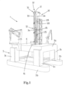
- FIG. 1 shows a vessel 1, here of the semi-submersible type.
- the vessel 1 comprises a floating hull 3 with a deckbox structure 3a having an upper or main deck 6 and a box bottom, one or more pontoons 3b, here two parallel pontoons , and multiple, here four, support columns 3c extending upward from the one or more pontoons 3b and supporting thereon the deckbox structure 3a.
- a moonpool 4 that extends through the deckbox structure 3a up to the main deck 6 of the deckbox structure.
- the height of the deckbox structure 3a between the main deck 6 and the box bottom is between 11 and 15 meters, e.g. about 12.5 meters.
- the vessel 1 comprises a wellbore activities installation with a tower 30 erected above the main deck 6, here of the deckbox structure 3a, and adapted to perform subsea wellbore related activities along at least one firing line 9 of the installation that vertically extends through the moonpool 4 into the sea.
- the tower 30 is provided with a crown block 31 at the top thereof and a travelling block 32 is suspended from the crown block 31 in a multiple fall arrangement of a cable 33.
- the cable is connected to one or more winches allowing the travelling block 32 to be moved up and down along an operative side of the tower 30 and in the firing line 9, so generally in a range above the main deck 6.
- the travelling block 32 for example, carries a topdrive 34 adapted for rotary drive of a drill string that is suspended from the topdrive and extends into a subsea well bore.
- the travelling block 32 is coupled to a trolley 35 that travels up and down along one or more vertical rails 36 provided on the tower 30.
- the vessel 1 is provided with a heave compensation system adapted to provide heave compensation for the cable 33 to provide a heave compensated motion of the travelling block 32 and thus of any drill string or the like suspended from the topdrive 35 during a drilling operation.
- the heave compensation may be active and/or passive, and may include one or more sheave compensators each supporting one of more cable sheaves that engage the cable from which the travelling block is suspended.
- the heave compensation may also, alternatively or in combination with sheave compensator(s), act directly on the winch(es), e.g. an active heave compensation control via a variable frequency electric drive of the winch(es).
- the vessel 1 is provided with a vertically mobile working deck 15 having a working deck surface 16, which working deck in a lowered position covers the moonpool 4, and which working deck surface 16 in the lowered position of the mobile working deck 15 is level with the main deck 6 .
- the vertically mobile deck 15 is supported by hydraulic cylinder type deck compensators 18 that are configured to provide a heave compensation of the mobile working deck 15.
- the mobile working deck 15 (see figure 1 ) is envisaged for use a stationary drill floor covering the moonpool 4 and generally level with the adjoining deck 6 of the hull.
- the deck compensators 18 are embodied to raise the vertically mobile working deck 15 from this lower stationary position and to bring this mobile deck 15 in a heave compensation motion range that lies higher than the lower stationary position. In this motion range the deck compensators 18 can effect a heave compensating motion of this deck 15, preferably synchronized with the heave compensation of the travelling block 32 that travels along a side of the tower 30.
- the heave compensation motion range of the working deck 15 is above the elevated position of the same working deck.
- the height of the elevated working deck 15 above the main deck 6 is between 4 and 6 meters, e.g. 5 meters.
- the heave compensation motion range has a height of between 7 and 12 meters, e.g. of approximately 10 meters, relative to the main deck 6.
- the maximum height of the working deck 15 above the main deck 6 is between 10 and 18 meters, e.g. approximately 15 meters.
- the working deck 15 may be provided with a personnel access platform supported underneath the working deck 15 that facilitates access to equipment underneath the working deck 15 during operations.
- At least one of a slip device, a riser spider device, and/or a diverter is supported by the mobile working deck 15.
- a diverter is arranged on the underside of the working deck 15.
- the slip device e.g. having mobile clamping jaws, is configured to support a suspended drill string or the like.
- a riser spider device is configured to support a suspended riser, e.g. during assembly and disassembly of a riser.
- the riser spider device has radially movable dogs that engage underneath a flange of a riser joint to support the weight of the riser string.
- a diverter is configured to divert a hydrocarbon and/or drilling mud stream from a subsea wellbore to the vessel.
- a hose or pipe connects the diverter to a mud handling facility onboard the vessel 1, e.g. located within the deckbox structure 3a.
- the vessel 1 allows for performing of drilling activities wherein the heave compensated mobile working deck 15 rests on the top of a rigid riser that extends down to a subsea well.
- the deckbox structure 3a comprises adjoining the moonpool 4 one or more wireline riser tensioner equipment rooms accommodating therein wireline riser tensioner equipment, e.g. comprising vertically oriented wireline riser tensioner cylinders.
- This equipment is configured to provide top tension to a riser that extends along the firing line between the seafloor and the vessel 1.
- such equipment is optional as the vessel 1 may be dedicated to riserless activities where no riser is needed, e.g. in well servicing or well maintenance activities.
- the vertically mobile working deck 15 is arranged above the moonpool 4, here with a partially removed moonpool wall 4a to show the location of firing line 9 through the moonpool 4.
- the tower 30 is a mast structure that is arranged on the hull adjacent the moonpool 4.
- multiple vertically mounted working deck compensator cylinders 18, here with piston rod 18a and cylinder body 18b, are arranged between the deckbox structure3a and the mobile working deck 15, here two sets of multiple compensator cylinders, e.g. two pairs, supporting the mobile working deck.
- These working deck compensator cylinders 18 are configured to provide a heave compensated motion of the working deck 15 relative to the deckbox structure.
- a first set of working deck compensator cylinders 18 is arranged outward of a first handling cart rail 81, relative to the moonpool 4, and a second set of working deck compensator cylinders 18 is arranged outward of a second handling cart rail 82, relative to the moonpool 4, so as to allow for passing a subsea object, e.g. a subsea stack, a subsea tree, a BOP, or other equipment on a handling cart in between the first and second set of working deck compensator cylinders 18.
- a subsea object e.g. a subsea stack, a subsea tree, a BOP, or other equipment on a handling cart in between the first and second set of working deck compensator cylinders 18.
- the cart is skiddable over the rails 81, 82.
- a part of the rails 81, 82 extends over the main deck 6, adjacent the moonpool 4.
- a further part of the rails 81, 82 extends along opposed sides of the moonpool 4.
- These further parts of the rails 81, 82 are preferably removable or movable, e.g. axially retractable and extendible, foldable, etc.
- the multiple vertically mounted working deck compensator cylinders 18 are, preferably, secured at a lower end thereof to a lower deck of the deckbox structure, e.g. the lowermost deck of the deckbox structure in view of having maximum height for these cylinders 18.
- Each of the cylinders 18 may be embodied as a linear, e.g. a single acting, hydraulic cylinder.
- the hydraulic heave motion compensation cylinder(s) 18 may be connected to a gas buffer, e.g. a nitrogen buffer, preferably via a medium separator between hydraulic liquid, e.g. oil, in the cylinder(s) 18 on the one hand and the gas in the gas buffer on the other hand, which arrangement is known in the art of heave compensation arrangements.
- a gas buffer e.g. a nitrogen buffer
- the cylinder(s) 18 may be connected to a motorized pump that is connected to a tank containing hydraulic fluid.
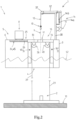
- Fig. 2 shows a schematic side view in cross section of an exemplary embodiment of a vessel in a first working position of lowering an object towards the seafloor.
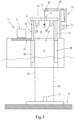
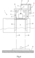
- Figures 3 , 4 and 5 show the same vessel in a subsequent second working position and third working position.
- the vessel 1 is configured for performing subsea wellbore related activities, e.g. workover activities, well maintenance, installing an object on the seafloor 10, e.g. on a subsea wellbore, e.g. on the wellhead, on a BOP already arranged on the seafloor, etc..
- subsea wellbore related activities e.g. workover activities, well maintenance, installing an object on the seafloor 10, e.g. on a subsea wellbore, e.g. on the wellhead, on a BOP already arranged on the seafloor, etc.
- the vessel 1 comprises a floating hull 3, a hoisting device 7, a mobile working deck 15, a mobile working deck compensator 18 and an object loading device 45.
- the floating hull 3 supports a deck 5 having a deck surface 6.
- the deck 5 is the main deck.
- the floating hull 3 furthermore has a moonpool 4, providing access to the sea for letting down objects into the sea and lifting objects out of the sea.
- the deck 6 has a moonpool opening 27.
- the vessel 1 furthermore comprises a mobile working deck 15.
- the mobile working deck 15 has a working deck surface 16.
- Figure 1 shows the mobile working deck in a lowered position, In the lowered position, the mobile working deck 15 covers the moonpool 4.
- the mobile working deck furthermore is level with the deck 5 of the vessel 1, i.e. the mobile working deck surface 16 and the deck surface 6 form one large deck surface that can be integrally used.
- the working deck surface 16 of the mobile working deck 15 is even flush with the deck surface 6 of the deck 5, Thus, a person or an object can pass from the deck onto the mobile working deck in a horizontal direction. No step or lowering has to be negotiated.
- the mobile working deck compensator 18 is connected with the floating hull 3 of the vessel 1 and the mobile working deck 15.
- the mobile working deck compensator 18 comprises four hydraulic mobile deck compensator cylinders 32. These hydraulic mobile deck compensator cylinders 32 are each located at a corner of the mobile working deck, and are with one end connected with the floating hull 3 of the vessel 1 and the mobile working deck 15.
- One pair of hydraulic mobile working deck cylinders 32 is located on one side of the moonpool 4. These cylinders are visible in the figures. One pair of hydraulic mobile working deck cylinders is located on an opposite side of the moonpool 4. These cylinders are not visible in the figure because they are located behind the two hydraulic mobile working deck cylinders 32 that are visible.
- the sliding deck section 24, support track 25 comprises tracks 26, in the embodiment shown skid rails, on opposite sides of the firing line 9, but between the two pairs of hydraulic mobile working deck cylinders 32.
- the mobile working deck compensator 18 is configured to lift the mobile working deck 15 out of the lowered position, shown in figure 1 , and into an elevated positon, shown in figures 2-4 .
- the mobile working deck compensator 18 can move the mobile working deck 15 between the lowered position and an elevated position.
- the mobile working deck compensator 18 is configured to provide a heave compensated motion of the mobile working deck when lifted in the elevated position, moving the mobile working deck relative to the elevated position between a heave compensation maximum height position and the heave compensation minimum height position.
- the mobile working deck compensator can keep the mobile working deck, when lifted in the elevated position, substantially stationary relative to the seafloor.
- the vessel 1 has a multipurpose tower 30.
- the multipurpose tower comprises a mast that is mounted on the floating hull 3.
- the vessel 1 has a winch system comprising a hoisting winch 11 and a hoisting cable 12 connected to the hoisting winch 11.
- the block 32 serves for connecting with the object 8 to be lowered to, or lifted from, the seafloor 10. Therefore the length of the cable 12 is sufficient to reach the seafloor 10.
- the cable 12 is arranged in a single fall arrangement, so with the hoisting block 13 at the end thereof as shown in the figures.
- the block 13 has at least one sheave around which the cable 12 passes.
- the cable 12 may have a terminal end that is embodied as a dead end.
- the cable 12 is connected at either end thereof to a winch, e.g. to allow for increase speed and/or redundancy.
- one end of the cable is connected to a winch and the other end to a heave motion compensation system.
- the cable 12 is a synthetic fibre rope.
- the tower 30 here is provided with a top sheave 37 from which the cable 12 is suspended in the firing line 9.
- the top sheave 37 may be arranged in proximity of the crown block 31 or even combined therewith.
- the firing line 9 is a virtual line indicating the vertical trajectory along which an object 8 can be lowered through the moonpool 4.
- the winch system furthermore comprises a heave motion compensation system 14, adapted to provide heave compensation for the hoisting cable 12 to provide a heave compensated motion of the travelling hoist block 13.
- heave compensation systems for winch driven cables are generally known in the art and typically comprise active and/or passive heave compensation, e.g. provided by a heave compensator cylinder 14a supporting a sheave 14b guiding the hoisting cable 12. Because these type of heave compensation systems are generally known, it will not be discussed in detail herein.
- the mobile working deck 15 is provided with a hoisting cable opening 17, aligned with the firing line 9.
- the opening 17 may be dimensioned so as to allow for passing through the travelling hoist block 13 and the hoisting cable 12 .
- the opening 17 is too small for passage of the hoist block 13.
- the hoist block 13 is fitted to the cable, e.g. the single fall cable 12, after first the cable 12 is passed through the opening 17.
- the opening 17 may also be larger than required for passing through both the cable 12 and the hoisting block 13, e.g. dimensioned to pass through an object 8 to be lowered to the seafloor 10.
- the vessel 1 is provided with a drilling tubulars storage rack 120 that is mounted on the hull 3, e.g. the deckbox structure, e.g. multi-joint drill pipe stands storage rack, e.g. a rotary storage rack.
- the drilling tubulars storage rack is adapted for storage of drilling tubulars in vertical orientation therein.
- the vessel, e.g. the mast structure 30, is provided with a racker system that is adapted to move a drilling tubular between the storage rack and a position aligned with the firing line.
- the racker system is heave compensated and is configured to bring a drilling tubular removed from the storage rack in a heave compensation motion that is synchronized with the heave compensation motion of the mobile working deck 15.
- the racker comprises a vertical motion arm assemblies rail, wherein at least one, e.g. multiple, motion arm assembly 125 is mounted on said vertical motion arm assemblies rail, each motion arm assembly having a base that is vertically mobile along said vertical motion arm assemblies rail by a drive configured to provide said heave compensation motion that is synchronized with the heave compensation motion of the mobile working deck.
- each motion arm assembly 125 further having an extensible, e.g.
- telescopic, arm that is mounted via a vertical axis slew bearing on said base so as to allow for extension and retraction of said arm as well as slewing motion of said telescopic arm about said vertical slew axis, wherein said arm is adapted to support a tubulars gripper tool at an end of said arm, so as to allow for gripping of a drilling tubulars by means of the tubular gripper tool.
- the object loading device 45 for introducing an object below the mobile working deck 15 and in the firing line 9, is a sliding deck section 24.
- the sliding deck section 24 is supported on a track 25 comprising tracks 26 on opposite sides of the firing line 9.
- the sliding deck section is located adjacent the moonpool opening 27 in the deck 5, which position is shown in figures 1 and 2 .
- the sliding deck section 24 can be slid over the moonpool opening 27 in the main deck 5 for moving an object 8, while supported by the sliding deck section, into the firing line 9 and below the mobile working deck 15, when the mobile working deck is in the elevated position, which is shown in figures 3-5 .
- the mobile working deck compensators 18 are configured to support the mobile working deck 15 during such operation in the heave compensation maximum height position, to provide additional clearance between the deck surface 6 and the bottom side of the mobile working deck 15, for introducing large sized objects 8 into the firing line and below the mobile working deck.
- the object 8 is coupled to the travelling hoist block 13, to enable the winch system with winch 11 and cable 12 to move the object along the firing line 9 below the mobile working deck, more in particular, to lower the object 8 towards the seafloor 10, more in particular towards the subsea wellbore 2.
- the vessel 1 furthermore comprises two or more, e.g. four, guide wire winches 28 and for each guide wire winch a guide wire 29 connected to the guide wire winch.
- the guide wires 29 are embodied to extend from the mobile deck 15 down to the seafloor 10, for example where the lower end of each guide wire 29 is connected to the subsea wellbore 2, in the embodiment shown to a well template 46.
- the guide wires 29 extend parallel to and spaced from the firing line 9.
- the guide wire winches 28 each comprise a heave compensation system, e.g. based on a variable frequency electric drive of each winch 28.
- the winches 28 are adapted to keep the guide wire 29, when fixed to a subsea well or the like, under substantially constant tension for guiding an object 8 being lowered towards, or lifted from, the seafloor along the firing line.
- the tensioning of the one or more guide wires 29 can also be achieved by means of the mobile working deck compensator 18 that provides the mobile working deck with heave compensation.
- this heave compensation can provide the guide wire winch with heave compensation, and can thus be used to keep the guide wire(s) 29, when fixed to a subsea component, e.g. the well head, under substantially constant tension. This is beneficial since it is not required to continuously roll the guide wire on and of the guide wire winch 29, or over a heave compensated sheave, to provide heave compensation, which will lengthen the lifetime of the guide wire 29.
- the guide wire winches 28 are each mounted below the deck surface 16 of the mobile working deck 15. This allows to provide the mobile working deck with a clean deck surface, which is in particular beneficial when the mobile working deck is in the lowered position and the deck surface of the mobile working deck 15 is level with the deck surface 6 of the main deck of the vessel, see figures 1 and 2 .
- the heave compensation system of the guide wire winches 28 is used to keep the guide wires 29 under a substantially constant tension.
- the mobile working deck 15 While the mobile working deck 15 is in the elevated position thereof and an object 8 is being moved into the firing line 9, the mobile working deck will, preferably, be in a fixed positon relative to the main deck 5, and the heave compensation system of the guide wire winches 28 is used to keep the guide wires 29 under a substantially constant tension. Once the mobile working deck 15 is heave compensated, the guide wire winches 29 no longer need to provide heave compensation.
- the vessel 1 allows for installing the object 8 on to the seafloor, more in particular on the subsea wellbore, e.g. the wellhead thereof.
- the object loading device 45 in an embodiment shown as a sliding deck section, can be used for positioning an object 8 below the mobile working deck 15, when raised in the elevated position thereof, and in the firing line 9, see figures 3 and 4 .
- the object 8 can be moved in a substantially horizontal direction from the deck 5 into the firing line 9 and below the mobile working deck 15, e.g. over rails 81, 82.
- the object 8 After the object 8 has been connected with the travelling block 13, and with the guide wires 29, the object 8 is lifted from the sliding deck section 24, which is subsequently retracted, such that the object 8 can be lowered towards the subsea wellbore 2 using the winch system 7. While it is lowered the object 8 is guide by the guide wires 29, and is thus positioned correct relative to the subsea wellbore, see figure 5 .
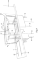
- Figure 6 illustrates that on the mobile working deck 15 there may be one or more rail sections 81a, 82a that are embodied to line up with corresponding rail sections 81, 82 on the main deck 5 when the mobile deck 15 is in its lowered stationary position.
- the rail sections 81, 82 pass on opposed sides of the opening 17, as preferred.
- Figure 8 also illustrates that, in an embodiment, the vertically mobile working deck 15 comprises a frame 83, here rectangular as preferred, defining a central passage 84 for passing through the hoisting cable, here also with the travelling hoisting block attached to the hoisting cable 12, and here also the object while coupled to the hoisting block 13 and suspended from the winch system.
- deck segments 85 of the deck 15 are configured to cover this central passage 84 to provide a deck surface over that opening, which one or more deck segments 85 can be moved, i.e. pivoted or removed, relative to the frame 84 of the vertically mobile working deck to open said central opening.
- the opening 84 is larger in cross-sectional horizontal dimensions than the hoisting cable opening 17, allowing for the block 13 or even an object suspended from the block 13 to pass through the larger opening 84 once the one or more deck segments 85 have been removed or retracted.
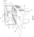
- FIG 9 illustrates an embodiment wherein an wire guided object carrier 90 is used.
- This carrier 90 is embodied to be brought under the mobile working deck 15, e.g. the deck 15 being first raised in its elevated position.
- the carrier 90 is embodied to be connected to the one or more guide wires 29, e.g. to each of two, three, or, as preferred, four guide wires 29.
- the carrier 90 is to be secured to the hoisting block 13 and the cable 12 so as to be lowered and lifted guided by the guide wires 29 to and from the seafloor, e.g. the wellhead or other object arranged on the seafloor.
- the object carrier 90 is proposed to receive an object 8, e.g. the carrier 90 forming a sort of cage in which the object 8 is held.
- Figures 9 and 10 show the carrier 90 without the object 8.
- the object 8 is secured to the carrier 90 in a releasable manner.
- the assembly of object 8 and carrier 90 is moved as a unit underneath the lifted mobile working deck 15 and into the firing line 9.
- the hoisting block is secured to the carrier 90.
- the carrier 90 is connected to the one or more guide wires 29.
- the assembly is then lowered towards the seafloor using winch 11 and cable 12.
- the object 8 is landed onto a subsea wellhead 3.
- the object 8 is released from the carrier 90 and the carrier 90 brought back above the water surface, below the mobile working deck.
- the carrier 90 can then be removed from the space below the working deck 15 if desired.
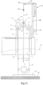
- Figure 11 shows a schematic side view in cross section of the vessel 1 of figure 1 in an alternative wellbore related activity.
- the vessel 1 is used for performing wellbore related activities using a wellbore-related activity system 47.
- the wellbore-related activity tool comprises a winch 48, a wire or coilable duct 49, and a subsea tool, e.g. a wellbore tool 50, at the end of the wire or coilable duct, in a subsea wellbore 2.
- a wellbore related activity system 47 can for example be a coiled tubing system or a wire line system, which are generally known system. With such a system, the winch 48 can be used for lowering and lifting the wire or coilable duct 49 and the tool 50.
- a coiled tubing injector head 51 can be used, for example having opposite tracks configured for engaging the coiled tubing duct 49 between them and moving the coiled tubing duct 49 to lift and lower the tool 50.
- a lubricator can be used.
- the winch 48 and/or the injector head 51 is placed on the mobile deck 15.
- the guide wires 29 have been connected to the subsea wellbore 2, more in particular to the well template 46 of the subsea wellbore, and can thus be used for guiding the tool 50.
- the heave compensated mobile working deck can be used for supporting the wellbore-related activity system, e.g. the coiled tubing system, thereon, there is no need for providing the wellbore-related activity system with a dedicated heave compensation device.
- the coilable duct or wire passing through an opening in the deck, preferably the opening 17, the tool 50 can be connected to the one or more guide wires 29.
- the mobile working deck compensator 18 can be used to lift the mobile working deck 15 into the elevated position, and to provide the mobile working deck with heave compensated motion.
- both the guide wires 29 and the wellbore activity tool 50 are in a substantially fixed position relative to the wellbore. Thus, no additional heave compensation, for example by the heave compensation device of the guide wire winches, is required.
- the winch 48 is used in combination with an injector head or other tool transportation device, comprising opposed tracks, to lower the tool towards the subsea wellbore.
- the guide wires 29 guide the tool 50, and make sure it lands in a correct position on the wellbore, in the embodiment shown on the object mounted on the wellbore, e.g. the wellhead.
- ROV remotely operated vehicle
- the guide wires 29 may first be used to lower an object 8 onto the seafloor, e.g. onto a wellhead 2, e.g. a subsea tree. Then the guide wires may be used to guide a tool 50 towards the object 8, e.g. onto, into or even through the object 8 and into the subsea wellbore itself.
- Figure 12 illustrates an embodiment wherein the vessel 1 furthermore comprises a moonpool deck 19 of the hull that is located below the main deck 5 of the hull.
- a cart track 20 is located below the main deck 5, preferably located on the moonpool deck 19.
- the cart track 20 comprises tracks 21 passing on opposite sides of the firing line 9.
- the track 20 is configured for moving a cart 22 and/or the object 8 over said track(s), while the cart and/or object is suspended from or supported by the cart track, from the moonpool deck 19 into the firing line 9 and below the mobile working deck 15.
- This allows for the object 8 to be coupled with the travelling hoist block 13, and/or the mobile working deck 15, and/or a coupling device, e.g. a tubular, supported by the mobile deck, and/or guide wires 29.
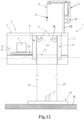
- Figure 13 illustrates an embodiment wherein the vertically mobile working deck 15 is provided with a second floor 66, which second floor 66 is suspended below working deck surface 16 of the mobile working deck 15.
- the second floor 66 is level with the deck surface 6 of the main deck 5 of the vessel 1 when the mobile working deck 15 is in the elevated position, or, possibly, when in the heave compensation maximum height position.
- the second floor 66 comprises a frame 67 defining a central passage 68 and one or more deck segments 69 that are configured to cover this central passage to provide a deck surface over that passage.
- the one or more deck segments 69 can be removed, e.g. pivoted or removed, relative to the frame 67 to open the central passage 38 for passing through an object 8 supported by the cable 12 and hoisting block 13.
Landscapes
- Engineering & Computer Science (AREA)
- Mining & Mineral Resources (AREA)
- Geology (AREA)
- Life Sciences & Earth Sciences (AREA)
- Physics & Mathematics (AREA)
- General Life Sciences & Earth Sciences (AREA)
- Geochemistry & Mineralogy (AREA)
- Fluid Mechanics (AREA)
- Environmental & Geological Engineering (AREA)
- Mechanical Engineering (AREA)
- Structural Engineering (AREA)
- Chemical & Material Sciences (AREA)
- Ocean & Marine Engineering (AREA)
- Civil Engineering (AREA)
- Architecture (AREA)
- Combustion & Propulsion (AREA)
- Ship Loading And Unloading (AREA)
- Types And Forms Of Lifts (AREA)
Claims (15)
- Wasserfahrzeug (1) zum Durchführen von Aktivitäten in Bezug auf ein Unterwasserbohrloch, wobei das Wasserfahrzeug umfasst:- einen schwimmenden Rumpf (3), der einen Moonpool (4) und ein Hauptdeck (5) mit einer Deckfläche (6) und mit einer Moonpoolöffnung (27) aufweist;- eine Hebevorrichtung (30), die an dem schwimmenden Rumpf (3) angebracht ist und mit einem Windensystem versehen ist, wobei das Windensystem zum Absenken eines Objekts (8) entlang einer Firing-Line (9) durch den Moonpool zu einem Meeresboden (10) ausgestaltet ist, wobei das Windensystem zum Anheben eines Objekts (8) von einem Meeresboden (10) entlang einer Firing-Line (9) durch den Moonpool (4) ausgestaltet ist, wobei das Windensystem umfasst:- eine Hebewinde (11) und ein mit der Hebewinde verbundenes Hebekabel (12), wobei das Hebekabel (12) an der Hebevorrichtung (30) entlang der Firing-Line (9) aufgehängt ist;- einen verfahrbaren Hebeblock (13), der von dem Hebeseil (12) zum Verbinden mit dem Objekt (8), das entlang der Firing-Line (9) auf den Meeresboden (10) abzusenken oder von diesem zu heben ist, gehalten wird; und- ein Seegangkompensationssystem (14), das ausgestaltet ist, um eine Seegangkompensation für das Hebekabel (12) bereitzustellen, um eine seegangkompensierte Bewegung des verfahrbaren Hebeblocks (13) bereitzustellen;- ein vertikal bewegliches Arbeitsdeck (15), wobei das bewegliche Arbeitsdeck eine Arbeitsdeckfläche (16) mit einer Hebekabelöffnung (17) aufweist, die zu der Firing-Line (9) ausgerichtet ist und die zum Durchführen von zumindest dem Hebekabel (12) ausgestaltet ist, wobei das bewegliche Arbeitsdeck (15) in einer abgesenkten Position davon den Moonpool (4) bedeckt, und wobei die Arbeitsdeckfläche (16) in der abgesenkten Position des beweglichen Arbeitsdecks (15) auf gleicher Höhe, vorzugsweise bündig, mit der Deckfläche (6) des Hauptdecks (5) des Rumpfes (3) ist;- einen Kompensator (18) für ein bewegliches Deck, wobei der Kompensator für ein bewegliches Deck mit dem schwimmenden Rumpf (3) des Wasserfahrzeugs (1) und mit dem vertikal beweglichen Arbeitsdeck (15) verbunden ist,
wobei der Kompensator (18) für ein bewegliche Arbeitsdeck ausgestaltet ist, um das bewegliche Arbeitsdeck (15) aus der abgesenkten Position anzuheben, um das bewegliche Arbeitsdeck zwischen der abgesenkten Position und einer angehobenen Position davon zu bewegen, und um eine seegangkompensierte Bewegung des beweglichen Arbeitsdecks (15) bereitzustellen, wenn es in die angehobene Position angehoben ist, wobei das bewegliche Deck zwischen einer Position mit maximaler Seegangkompensationshöhe und einer Position mit minimaler Seegangkompensationshöhe bewegt wird;- eine Objektladevorrichtung (45; 24; 81, 82), die zum Einführen des Objekts (8) unter das bewegliche Arbeitsdeck (15) und in die Firing-Line (9) ausgestaltet ist, so dass das Objekt (8) mit dem verfahrbaren Hebeblock (13) gekoppelt werden kann, um es dem Windensystem zu ermöglichen, das Objekt entlang der Firing-Line (9) unterhalb des bewegliches Arbeitsdecks (15) und auf den Meeresboden (10) abzusenken. - Wasserfahrzeug nach Anspruch 1, wobei das Wasserfahrzeug (1) ein halbtauchfähiges Fahrzeug ist, wobei das Wasserfahrzeug (1) vorzugsweise weiterhin umfasst:- ein Moonpool-Deck (19) des Rumpfes, das unterhalb des Hauptdecks (5) des Rumpfes angeordnet ist, und- eine Wagenbahn (20), die unterhalb des Hauptdecks (5) angeordnet ist, vorzugsweise auf dem Moonpool-Deck (19) angeordnet ist,wobei die Wagenbahn (20) Schienen (21) umfasst, die auf gegenüberliegenden Seiten der Firing-Line (9) verlaufen und zum Bewegen eines Wagens (22) und/oder des Objekts über die Schienen von dem Moonpool-Deck (19) in die Firing-Line (9) und unter das bewegliche Arbeitsdeck (15) ausgestaltet sind, während der Wagen und/oder das Objekt an der Wagenbahn aufgehängt ist oder von ihr gehalten wird, um dem Objekt (8) zu ermöglichen, mit dem verfahrbaren Hebeblock (13) und/oder dem beweglichen Arbeitsdeck (15) und/oder einer Kopplungsvorrichtung (23) gekoppelt zu werden, z. B. einem Rohr, das von dem beweglichen Deck gehalten wird, und/oder Führungsdrähten.
- Wasserfahrzeug nach einem oder mehreren der vorhergehenden Ansprüche, wobei das Wasserfahrzeug (1) ferner umfasst:- eine Wagenbahn (20; 81, 82), die auf dem Hauptdeck (5) des Wasserfahrzeugs (1) vorgesehen ist,wobei die auf dem Hauptdeck (5) vorgesehene Wagenbahn (20; 81, 82) Schienen (21 ; 81, 82) umfasst, die auf gegenüberliegenden Seiten der Firing-Line (9) verlaufen und zum Bewegen eines Wagens (22) und/oder des Objekts (8), während der Wagen und/oder das Objekt von der Wagenbahn gehalten wird, in einer im Wesentlichen horizontalen Richtung von dem Hauptdeck (5) in die Firing-Line (9) und unter das bewegliche Arbeitsdeck (15) in der angehobenen Position davon ausgestaltet sind, wobei sich das bewegliche Arbeitsdeck während des Betriebs vorzugsweise in der Position mit maximaler Seegangkompensationshöhe davon befindet, um dem Objekt (8) zu ermöglichen, mit dem verfahrbaren Block (13) und/oder dem beweglichen Arbeitsdeck (15) und/oder einer Kopplungsvorrichtung (23) gekoppelt zu werden, z. B. einem Rohr, das von der beweglichen Plattform und/oder Führungsdrähten gehalten wird.
- Wasserfahrzeug nach einem oder mehreren der vorhergehenden Ansprüche, wobei das Wasserfahrzeug (1) ferner umfasst:- einen verschiebbaren Decksabschnitt (24), der vorzugsweise auf einer Bahn (25) gehalten wird, die auf gegenüberliegenden Seiten der Firing-Line (9) verlaufende Schienen (26) umfasst,wobei der verschiebbare Decksabschnitt (24) in eine Position zurückziehbar ist, die benachbart zu der Moonpool-Öffnung (27) in dem Deck (5) angeordnet ist, und wobei der verschiebbare Decksabschnitt (24) über die Moonpool-Öffnung (27) in dem Deck (5) verschoben werden kann, wodurch z.B. das Objekt (8), während es von dem verschiebbaren Deckabschnitt gehalten wird, in die Firing-Line (9) und unter das bewegliche Arbeitsdeck (15) in einer angehobenen Position davon, vorzugsweise in der Position mit maximaler Seegangkompensationshöhe davon, bewegt wird, um dem Objekt (8) zu ermöglichen, mit dem verfahrbaren Hebeblock (13) und/oder dem beweglichen Arbeitsdeck (15) und/oder einer Kopplungsvorrichtung (23) gekoppelt zu werden, z. B. einem Rohr, das von dem beweglichen Deck gehalten wird, und/oder Führungsdrähten.
- Wasserfahrzeug nach einem oder mehreren der vorhergehenden Ansprüche, wobei das Wasserfahrzeug (1) ferner umfasst:- mindestens eine an dem vertikal beweglichen Arbeitsdeck (15), z.B. an der Unterseite davon, angebrachte Führungsdrahtwinde (28) und einen mit der Führungsdrahtwinde (28) verbundenen Führungsdraht (29), wobei der Führungsdraht mit einem Unterwasseranker, z.B. mit einem Unterwasserbohrloch (2), z.B. mit einem an diesem Bohrloch angebrachten Unterwasserstapel oder mit einer Bohrlochschablone, zu verbinden ist, so dass er sich parallel zu und beabstandet von der Firing-Line erstreckt, undwobei vorzugsweise die Führungsdrahtwinde (28) ein Seegangkompensationssystem (30) umfasst, das ausgestaltet ist, um den Führungsdraht (29), wenn er an einem Unterwasseranker, z.B. an dem Unterwasserbohrloch (2), befestigt ist, unter einer im Wesentlichen konstanten Spannung zu halten, wenn das vertikal bewegliche Arbeitsdeck (15) in einer festen Position, z.B. einer angehobenen Position, relativ zu dem Wasserfahrzeug (1) gehalten wird, um eine Führung parallel zu und versetzt von der Firing-Line (9) bereitzustellen, um das Objekt (8; 50), das in Richtung des Meeresbodens (10) abgesenkt oder von diesem angehoben wird, entlang der Firing-Line (9) zu führen, wobei vorzugsweise die mindestens eine Führungsdrahtwinde (28) unter der Arbeitsdeckfläche (16) des beweglichen Arbeitsdecks (15) angeordnet ist.
- Wasserfahrzeug nach einem oder mehreren der vorhergehenden Ansprüche, wobei der Kompensator für das bewegliche Arbeitsdeck (18) zwei oder mehr, vorzugsweise vier, z. B. zwei Paare, hydraulische bewegliche Deckkompensatorzylinder (18; 31) umfasst, die jeweils zwischen dem schwimmenden Rumpf (3) des Wasserfahrzeugs (1) und dem vertikal beweglichen Arbeitsdeck (15) vorgesehen sind, wobei jeder Deckkompensatorzylinder vorzugsweise eine zu der Firing-Line (9) parallele Arbeitslinie (32) aufweist.
- Wasserfahrzeug nach einem oder mehreren der vorhergehenden Ansprüche, wobei das vertikal bewegliche Arbeitsdeck (15) umfasst:- einen Rahmen (83), der einen zentralen Durchgang (84) zum Durchführen des Hebekabels, möglicherweise mit dem verfahrbaren Hebeblock, der an dem Hebekabel angebracht ist, möglicherweise auch mit dem Objekt, während es mit dem Hebeblock gekoppelt und an dem Windensystem aufgehängt ist, definiert, und- ein oder mehrere Decksegmente (85), die ausgestaltet sind, um den zentralen Durchgang (84) abzudecken, um eine Deckfläche über dieser Öffnung bereitzustellen, wobei das eine oder die mehreren Decksegmente (85) relativ zu dem Rahmen (83) des vertikal beweglichen Arbeitsdecks bewegt, d.h. geschwenkt oder entfernt, werden können, um die zentrale Öffnung zu öffnen.
- Wasserfahrzeug nach einem oder mehreren der vorhergehenden Ansprüche, wobei das bewegliche Arbeitsdeck (15) mit einem zweiten Boden (66) versehen ist, wobei der zweite Boden (66) unter der Arbeitsdeckfläche des beweglichen Arbeitsdecks (15) aufgehängt ist, wobei vorzugsweise der zweite Boden (66) auf gleicher Höhe mit der Deckfläche (6) des Wasserfahrzeugs (1) ist, wenn sich das bewegliche Arbeitsdeck (15) in der angehobenen Position, vorzugsweise in der Position mit maximaler Seegangkompensationshöhe, befindet.
- Wasserfahrzeug nach Anspruch 8, wobei der zweite Boden (66) umfasst:- einen Rahmen (67), der einen zentralen Durchgang (68) definiert; und- ein oder mehrere Decksegmente (69), die ausgestaltet sind, um den zentralen Durchgang (68) abzudecken, um eine Deckfläche über diesem Durchgang bereitzustellen,wobei das eine oder die mehreren Decksegmente (69) entfernt werden können, z.B. relativ zu dem Rahmen geschwenkt oder entfernt, um den zentralen Durchgang (68) zum Durchführen des Objekts (8; 50), das z.B. von dem Kabel (12) und dem Hebeblock (13) gehalten wird, zu öffnen.
- Wasserfahrzeug nach einem oder mehreren der vorhergehenden Ansprüche, wobei das Wasserfahrzeug (1) ferner ein Seegangkompensations-Steuersystem (40) umfasst, wobei das Seegangkompensations-Steuersystem das Seegangkompensationssystem (40) des Windensystems steuert und den Kompensator (18) für das bewegliche Deck steuert und, falls vorhanden, die mindestens eine Führungsdrahtwinde (28) steuert, so dass der verfahrbare Hebeblock, das vertikal bewegliche Arbeitsdeck und ein oder mehrere Führungsdrähte mit einer synchronen Seegangkompensation versehen werden, die von dem Seegangkompensations-Steuersystem (40) gesteuert wird.
- Wasserfahrzeug nach einem oder mehreren der vorhergehenden Ansprüche, wobei der Abstand zwischen einer Unterseite (44) des beweglichen Arbeitsdecks (15), wenn es in der angehobenen Position, vorzugsweise in der Position mit maximaler Seegangkompensationshöhe, gehalten wird, und der Deckfläche (6) des Hauptdecks (5) des Wasserfahrzeugs (1) mindestens 3 Meter, vorzugsweise mindestens 4 Meter beträgt, um großen Objekten (8), d.h. mit einer Höhe von mehr als 2 Metern, zu ermöglichen, von dem Hauptdeck (5) des Wasserfahrzeugs (1) in die Firing-Line (9) und unter das bewegliche Arbeitsdeck (15) in einer im Wesentlichen horizontalen Richtung bewegt zu werden.
- Verfahren zum Installieren eines Objekts auf dem Meeresboden, z.B. auf einem Unterwasser-Bohrlochkopf, unter Verwendung eines Wasserfahrzeugs nach einem oder mehreren der vorhergehenden Ansprüche 1 - 14, wobei das Verfahren die Schritte umfasst:- Positionieren eines Objekts (8) unterhalb des beweglichen Arbeitsdecks und in der Firing-Line (9) unter Verwendung der Objektladevorrichtung (45);- Verbinden des Objekts mit dem verfahrbaren Hebeblock (13), wobei das Hebekabel (12) durch die Hebekabelöffnung (17) in dem beweglichen Arbeitsdeck (15) verläuft; und- Absenken des Objekts (8) auf den Meeresboden (10) mittels des Hebekabels (12) unter Verwendung des Windensystems.
- Verfahren nach Anspruch 12, wobei das Verfahren ferner die folgenden Schritte umfasst:- Anheben des beweglichen Arbeitsdecks (15) aus der abgesenkten Position davon in die angehobene Position davon; und- Bewegen des Objekts (8) in einer im Wesentlichen horizontalen Richtung von dem Hauptdeck (5) in die Firing-Line (9) und unter das angehobene bewegliche Arbeitsdeck (17).
- Verfahren zum Installieren eines Objekts (8) auf dem Meeresboden, z. B. auf einem Unterwasser-Bohrlochkopf, unter Verwendung eines Wasserfahrzeugs nach Anspruch 5, z. B. das Verfahren nach Anspruch 15 oder 16, wobei das Verfahren ferner die Schritte umfasst:- Ausfahren von mindestens einem Führungsdraht (29) von einer Führungsdrahtwinde (28), die auf dem beweglichen Arbeitsdeck (15) angeordnet ist;- Verbinden des mindestens einen Führungsdrahtes (29) mit einem Unterwasseranker, z.B. mit einem Unterwasserbohrloch (2), z.B. einer Bohrlochschablone eines Unterwasserbohrlochs;- Halten des Führungsdrahtes (29) unter einer im Wesentlichen konstanten Spannung,- Positionieren des Objekts (8) unter dem vertikal beweglichen Arbeitsdeck (15) in einer angehobenen Position davon und in der Firing-Line (9) unter Verwendung der Objektladevorrichtung (45);- Verbinden des Objekts (8) mit dem mindestens einen Führungsdraht (29),- Verbinden des Objekts (8) mit dem verfahrbaren Hebeblock (13), wobei das Hebekabel (12) durch die Hebekabelöffnung (17) in dem vertikal beweglichen Arbeitsdeck (15) verläuft; und- Absenken des Objekts (8) auf den Meeresboden (10) mittels des Hebekabels (12) unter Verwendung des Windensystems und geführt durch den mindestens einen Führungsdraht, wobei das Verfahren vorzugsweise ferner umfasst:- Halten des mindestens einen Führungsdrahtes unter einer im Wesentlichen konstanten Spannung mittels eines Seegangkompensationssystems der Führungsdrahtwinde (28), und/oder- Verwenden des Kompensators (18) für das bewegliche Arbeitsdeck, um eine seegangkompensierte Bewegung des beweglichen Arbeitsdecks (15) bereitzustellen und auch um den Führungsdraht unter einer im Wesentlichen konstanten Spannung zu halten.
- Verfahren zum Durchführen einer Aktivität in Bezug auf ein Bohrloch unter Verwendung eines Systems (47) für eine Aktivität in Bezug auf ein Bohrloch, wobei das System (47) für eine Aktivität in Bezug auf ein Bohrloch eine Winde (48), einen Draht oder eine aufwickelbare Leitung (49) und ein Unterwasserwerkzeug (50) umfasst, in einem Unterwasserbohrloch unter Verwendung eines Wasserfahrzeugs, das mindestens eine Führungsdrahtwinde nach Anspruch 6 umfasst, wobei das Verfahren die Schritte umfasst:- Verbinden des mindestens einen Führungsdrahtes (29) mit einem Unterwasseranker, z.B. mit einem Unterwasserbohrloch (2), und Verwenden eines Seegangkompensationssystems der Führungsdrahtwinde (28), um den Führungsdraht unter einer im Wesentlichen konstanten Spannung zu halten;- Positionieren von mindestens einem Teil des Systems für eine Aktivität in Bezug auf ein Bohrloch auf der Deckfläche (16) des vertikal beweglichen Arbeitsdecks (15), z. B. dem Injektionskopf (51) für ein gewickeltes Rohr;- Positionieren des Unterwasserwerkzeugs, z. B. des Bohrlochwerkzeugs (50), unter dem vertikal beweglichen Arbeitsdeck (15), wobei der Draht oder die aufwickelbare Leitung (49) durch eine Öffnung, z. B. die Hebekabelöffnung (17), in dem vertikal beweglichen Arbeitsdeck (15) verläuft;- Verbinden des Werkzeugs (50) mit dem mindestens einen Führungsdraht (29);- Verwendung des Kompensators (18) für das bewegliche Arbeitsdeck, um das bewegliche Arbeitsdeck in eine angehobene Position zu heben;- Verwendung des Kompensators (18) für das bewegliche Arbeitsdeck, um das vertikal bewegliche Arbeitsdeck mit einer seegangkompensierten Bewegung zu versehen;- Verwenden des Kompensators (18) für das bewegliche Arbeitsdeck und/oder eines Seegangkompensationssystems der mindestens einen Führungsdrahtwinde (28), um den einen oder die mehreren Führungsdrähte (29) unter einer im Wesentlichen konstanten Spannung zu halten; und- Absenken des Werkzeugs (50) in Richtung des Meeresbodens, z. B. in das Unterwasserbohrloch.
Applications Claiming Priority (4)
| Application Number | Priority Date | Filing Date | Title |
|---|---|---|---|
| NL2019896 | 2017-11-13 | ||
| NL2020458 | 2018-02-19 | ||
| NL2020481 | 2018-02-22 | ||
| PCT/NL2018/050759 WO2019093899A1 (en) | 2017-11-13 | 2018-11-13 | Vessel and method for performing subsea wellbore related activities |
Publications (2)
| Publication Number | Publication Date |
|---|---|
| EP3710351A1 EP3710351A1 (de) | 2020-09-23 |
| EP3710351B1 true EP3710351B1 (de) | 2023-08-09 |
Family
ID=65228612
Family Applications (1)
| Application Number | Title | Priority Date | Filing Date |
|---|---|---|---|
| EP18839746.7A Active EP3710351B1 (de) | 2017-11-13 | 2018-11-13 | Schiff und verfahren zur durchführung von unterirdischen bohrlochbezogenen aktivitäten |
Country Status (3)
| Country | Link |
|---|---|
| EP (1) | EP3710351B1 (de) |
| CN (1) | CN111491857B (de) |
| WO (1) | WO2019093899A1 (de) |
Families Citing this family (6)
| Publication number | Priority date | Publication date | Assignee | Title |
|---|---|---|---|---|
| DK180224B1 (en) * | 2018-06-06 | 2020-08-21 | Maersk Drilling As | Method and system for mitigating cable wear in a hoisting system |
| US11566478B2 (en) | 2019-08-29 | 2023-01-31 | Ensco International Incorporated | Compensated drill floor |
| WO2021102227A1 (en) * | 2019-11-21 | 2021-05-27 | Oceaneering International, Inc. | Apparatus and method for assisting deployment of coiled tubing |
| ES3009920T3 (en) * | 2019-12-05 | 2025-03-31 | Petroleo Brasileiro Sa Petrobras | Method for clearing flexible lines using coiled tubing from a well intervention rig |
| CN113027386B (zh) * | 2021-03-12 | 2022-10-14 | 中国船舶工业集团公司第七0八研究所 | 井口盘转运系统及其作业方法 |
| NO347905B1 (en) * | 2023-10-13 | 2024-05-06 | Kongshavn Industri As | Shielding tunnel device, system for safe installation of a christmas tree (XMT) and a method for safe installation of a surface XMT |
Family Cites Families (10)
| Publication number | Priority date | Publication date | Assignee | Title |
|---|---|---|---|---|
| US3681928A (en) * | 1970-09-15 | 1972-08-08 | Leonardus M J Vincken | Method and apparatus for carrying out underwater well operations |
| US3943868A (en) * | 1974-06-13 | 1976-03-16 | Global Marine Inc. | Heave compensation apparatus for a marine mining vessel |
| US4039177A (en) * | 1974-06-13 | 1977-08-02 | Global Marine Inc. | Heave compensation apparatus for a marine mining vessel |
| NZ240667A (en) * | 1990-12-10 | 1993-06-25 | Shell Int Research | Offshore oil drilling from drilling vessel in support of a compliant platform |
| US20110011320A1 (en) * | 2009-07-15 | 2011-01-20 | My Technologies, L.L.C. | Riser technology |
| US9266586B2 (en) * | 2012-05-11 | 2016-02-23 | Itrec B.V. | Offshore vessel and method of operation of such an offshore vessel |
| EP2983978B1 (de) * | 2013-04-12 | 2018-10-03 | Itrec B.V. | Schiff für unterwasserbohrlochoperationen |
| NL2012354B1 (en) * | 2014-03-03 | 2015-11-26 | Itrec Bv | Offshore drilling system, vessel and methods. |
| NL2012723B1 (en) * | 2014-04-30 | 2016-07-18 | Fugro Eng B V | Offshore drilling installation and method for offshore drilling. |
| NL2013680B1 (en) * | 2014-10-24 | 2016-10-05 | Itrec Bv | Offshore drilling system, vessel and method. |
-
2018
- 2018-11-13 EP EP18839746.7A patent/EP3710351B1/de active Active
- 2018-11-13 WO PCT/NL2018/050759 patent/WO2019093899A1/en not_active Ceased
- 2018-11-13 CN CN201880081913.7A patent/CN111491857B/zh active Active
Also Published As
| Publication number | Publication date |
|---|---|
| EP3710351A1 (de) | 2020-09-23 |
| WO2019093899A1 (en) | 2019-05-16 |
| CN111491857B (zh) | 2022-10-11 |
| CN111491857A (zh) | 2020-08-04 |
Similar Documents
| Publication | Publication Date | Title |
|---|---|---|
| US11781384B2 (en) | Drilling installation: handling system, method for independent operations | |
| EP3710351B1 (de) | Schiff und verfahren zur durchführung von unterirdischen bohrlochbezogenen aktivitäten | |
| EP2847417B1 (de) | Offshore-schiff und verfahren für den betrieb eines derartigen offshore-schiffes | |
| US10323467B2 (en) | Offshore drilling rig and a method of operating the same | |
| US9624739B2 (en) | Drilling rig | |
| WO2014108542A2 (en) | Drilling rig | |
| US10570672B2 (en) | Offshore drilling rig and a method of operating the same | |
| EP3755618B1 (de) | Schiff und verfahren zur durchführung von unterirdischen bohrlochbezogenen aktivitäten, z.b. überholungsoperationen, bohrlochinstandhaltung, installation eines objekts auf einem unterirdischen bohrloch | |
| US10890034B2 (en) | Combination of a drilling installation and a control and signal lines deployment module and method of use | |
| EP3829967B1 (de) | Halbtauchfähiges schiff | |
| CN118306513A (zh) | 用于例如恶劣环境下的半潜式钻井船 | |
| NL2016059B1 (en) | Drilling installation; Handling system, method for independent operations. | |
| NL2023601B1 (en) | Semi-submersible floating offshore vessel | |
| NL2014765B1 (en) | Drilling installation; Handling system, method for independent operations. |
Legal Events
| Date | Code | Title | Description |
|---|---|---|---|
| STAA | Information on the status of an ep patent application or granted ep patent |
Free format text: STATUS: UNKNOWN |
|
| STAA | Information on the status of an ep patent application or granted ep patent |
Free format text: STATUS: THE INTERNATIONAL PUBLICATION HAS BEEN MADE |
|
| PUAI | Public reference made under article 153(3) epc to a published international application that has entered the european phase |
Free format text: ORIGINAL CODE: 0009012 |
|
| STAA | Information on the status of an ep patent application or granted ep patent |
Free format text: STATUS: REQUEST FOR EXAMINATION WAS MADE |
|
| 17P | Request for examination filed |
Effective date: 20200610 |
|
| AK | Designated contracting states |
Kind code of ref document: A1 Designated state(s): AL AT BE BG CH CY CZ DE DK EE ES FI FR GB GR HR HU IE IS IT LI LT LU LV MC MK MT NL NO PL PT RO RS SE SI SK SM TR |
|
| AX | Request for extension of the european patent |
Extension state: BA ME |
|
| DAV | Request for validation of the european patent (deleted) | ||
| DAX | Request for extension of the european patent (deleted) | ||
| GRAP | Despatch of communication of intention to grant a patent |
Free format text: ORIGINAL CODE: EPIDOSNIGR1 |
|
| STAA | Information on the status of an ep patent application or granted ep patent |
Free format text: STATUS: GRANT OF PATENT IS INTENDED |
|
| RIC1 | Information provided on ipc code assigned before grant |
Ipc: E21B 7/132 20060101ALI20230208BHEP Ipc: E21B 19/00 20060101ALI20230208BHEP Ipc: E21B 41/10 20060101ALI20230208BHEP Ipc: B63B 35/44 20060101AFI20230208BHEP |
|
| INTG | Intention to grant announced |
Effective date: 20230310 |
|
| GRAS | Grant fee paid |
Free format text: ORIGINAL CODE: EPIDOSNIGR3 |
|
| GRAA | (expected) grant |
Free format text: ORIGINAL CODE: 0009210 |
|
| STAA | Information on the status of an ep patent application or granted ep patent |
Free format text: STATUS: THE PATENT HAS BEEN GRANTED |
|
| AK | Designated contracting states |
Kind code of ref document: B1 Designated state(s): AL AT BE BG CH CY CZ DE DK EE ES FI FR GB GR HR HU IE IS IT LI LT LU LV MC MK MT NL NO PL PT RO RS SE SI SK SM TR |
|
| REG | Reference to a national code |
Ref country code: GB Ref legal event code: FG4D |
|
| REG | Reference to a national code |
Ref country code: CH Ref legal event code: EP |
|
| REG | Reference to a national code |
Ref country code: IE Ref legal event code: FG4D |
|
| REG | Reference to a national code |
Ref country code: DE Ref legal event code: R096 Ref document number: 602018055166 Country of ref document: DE |
|
| REG | Reference to a national code |
Ref country code: NL Ref legal event code: FP |
|
| REG | Reference to a national code |
Ref country code: NO Ref legal event code: T2 Effective date: 20230809 Ref country code: LT Ref legal event code: MG9D |
|
| REG | Reference to a national code |
Ref country code: AT Ref legal event code: MK05 Ref document number: 1597245 Country of ref document: AT Kind code of ref document: T Effective date: 20230809 |
|
| PG25 | Lapsed in a contracting state [announced via postgrant information from national office to epo] |
Ref country code: GR Free format text: LAPSE BECAUSE OF FAILURE TO SUBMIT A TRANSLATION OF THE DESCRIPTION OR TO PAY THE FEE WITHIN THE PRESCRIBED TIME-LIMIT Effective date: 20231110 |
|
| PG25 | Lapsed in a contracting state [announced via postgrant information from national office to epo] |
Ref country code: IS Free format text: LAPSE BECAUSE OF FAILURE TO SUBMIT A TRANSLATION OF THE DESCRIPTION OR TO PAY THE FEE WITHIN THE PRESCRIBED TIME-LIMIT Effective date: 20231209 |
|
| PG25 | Lapsed in a contracting state [announced via postgrant information from national office to epo] |
Ref country code: SE Free format text: LAPSE BECAUSE OF FAILURE TO SUBMIT A TRANSLATION OF THE DESCRIPTION OR TO PAY THE FEE WITHIN THE PRESCRIBED TIME-LIMIT Effective date: 20230809 Ref country code: RS Free format text: LAPSE BECAUSE OF FAILURE TO SUBMIT A TRANSLATION OF THE DESCRIPTION OR TO PAY THE FEE WITHIN THE PRESCRIBED TIME-LIMIT Effective date: 20230809 Ref country code: PT Free format text: LAPSE BECAUSE OF FAILURE TO SUBMIT A TRANSLATION OF THE DESCRIPTION OR TO PAY THE FEE WITHIN THE PRESCRIBED TIME-LIMIT Effective date: 20231211 Ref country code: LV Free format text: LAPSE BECAUSE OF FAILURE TO SUBMIT A TRANSLATION OF THE DESCRIPTION OR TO PAY THE FEE WITHIN THE PRESCRIBED TIME-LIMIT Effective date: 20230809 Ref country code: LT Free format text: LAPSE BECAUSE OF FAILURE TO SUBMIT A TRANSLATION OF THE DESCRIPTION OR TO PAY THE FEE WITHIN THE PRESCRIBED TIME-LIMIT Effective date: 20230809 Ref country code: IS Free format text: LAPSE BECAUSE OF FAILURE TO SUBMIT A TRANSLATION OF THE DESCRIPTION OR TO PAY THE FEE WITHIN THE PRESCRIBED TIME-LIMIT Effective date: 20231209 Ref country code: HR Free format text: LAPSE BECAUSE OF FAILURE TO SUBMIT A TRANSLATION OF THE DESCRIPTION OR TO PAY THE FEE WITHIN THE PRESCRIBED TIME-LIMIT Effective date: 20230809 Ref country code: GR Free format text: LAPSE BECAUSE OF FAILURE TO SUBMIT A TRANSLATION OF THE DESCRIPTION OR TO PAY THE FEE WITHIN THE PRESCRIBED TIME-LIMIT Effective date: 20231110 Ref country code: FI Free format text: LAPSE BECAUSE OF FAILURE TO SUBMIT A TRANSLATION OF THE DESCRIPTION OR TO PAY THE FEE WITHIN THE PRESCRIBED TIME-LIMIT Effective date: 20230809 Ref country code: AT Free format text: LAPSE BECAUSE OF FAILURE TO SUBMIT A TRANSLATION OF THE DESCRIPTION OR TO PAY THE FEE WITHIN THE PRESCRIBED TIME-LIMIT Effective date: 20230809 |
|
| PG25 | Lapsed in a contracting state [announced via postgrant information from national office to epo] |
Ref country code: PL Free format text: LAPSE BECAUSE OF FAILURE TO SUBMIT A TRANSLATION OF THE DESCRIPTION OR TO PAY THE FEE WITHIN THE PRESCRIBED TIME-LIMIT Effective date: 20230809 |
|
| PG25 | Lapsed in a contracting state [announced via postgrant information from national office to epo] |
Ref country code: ES Free format text: LAPSE BECAUSE OF FAILURE TO SUBMIT A TRANSLATION OF THE DESCRIPTION OR TO PAY THE FEE WITHIN THE PRESCRIBED TIME-LIMIT Effective date: 20230809 |
|
| PG25 | Lapsed in a contracting state [announced via postgrant information from national office to epo] |
Ref country code: SM Free format text: LAPSE BECAUSE OF FAILURE TO SUBMIT A TRANSLATION OF THE DESCRIPTION OR TO PAY THE FEE WITHIN THE PRESCRIBED TIME-LIMIT Effective date: 20230809 Ref country code: RO Free format text: LAPSE BECAUSE OF FAILURE TO SUBMIT A TRANSLATION OF THE DESCRIPTION OR TO PAY THE FEE WITHIN THE PRESCRIBED TIME-LIMIT Effective date: 20230809 Ref country code: ES Free format text: LAPSE BECAUSE OF FAILURE TO SUBMIT A TRANSLATION OF THE DESCRIPTION OR TO PAY THE FEE WITHIN THE PRESCRIBED TIME-LIMIT Effective date: 20230809 Ref country code: EE Free format text: LAPSE BECAUSE OF FAILURE TO SUBMIT A TRANSLATION OF THE DESCRIPTION OR TO PAY THE FEE WITHIN THE PRESCRIBED TIME-LIMIT Effective date: 20230809 Ref country code: DK Free format text: LAPSE BECAUSE OF FAILURE TO SUBMIT A TRANSLATION OF THE DESCRIPTION OR TO PAY THE FEE WITHIN THE PRESCRIBED TIME-LIMIT Effective date: 20230809 Ref country code: CZ Free format text: LAPSE BECAUSE OF FAILURE TO SUBMIT A TRANSLATION OF THE DESCRIPTION OR TO PAY THE FEE WITHIN THE PRESCRIBED TIME-LIMIT Effective date: 20230809 Ref country code: SK Free format text: LAPSE BECAUSE OF FAILURE TO SUBMIT A TRANSLATION OF THE DESCRIPTION OR TO PAY THE FEE WITHIN THE PRESCRIBED TIME-LIMIT Effective date: 20230809 |
|
| REG | Reference to a national code |
Ref country code: DE Ref legal event code: R097 Ref document number: 602018055166 Country of ref document: DE |
|
| PG25 | Lapsed in a contracting state [announced via postgrant information from national office to epo] |
Ref country code: IT Free format text: LAPSE BECAUSE OF FAILURE TO SUBMIT A TRANSLATION OF THE DESCRIPTION OR TO PAY THE FEE WITHIN THE PRESCRIBED TIME-LIMIT Effective date: 20230809 |
|
| REG | Reference to a national code |
Ref country code: DE Ref legal event code: R119 Ref document number: 602018055166 Country of ref document: DE |
|
| PLBE | No opposition filed within time limit |
Free format text: ORIGINAL CODE: 0009261 |
|
| STAA | Information on the status of an ep patent application or granted ep patent |
Free format text: STATUS: NO OPPOSITION FILED WITHIN TIME LIMIT |
|
| REG | Reference to a national code |
Ref country code: CH Ref legal event code: PL |
|
| PG25 | Lapsed in a contracting state [announced via postgrant information from national office to epo] |
Ref country code: MC Free format text: LAPSE BECAUSE OF FAILURE TO SUBMIT A TRANSLATION OF THE DESCRIPTION OR TO PAY THE FEE WITHIN THE PRESCRIBED TIME-LIMIT Effective date: 20230809 |
|
| PG25 | Lapsed in a contracting state [announced via postgrant information from national office to epo] |
Ref country code: LU Free format text: LAPSE BECAUSE OF NON-PAYMENT OF DUE FEES Effective date: 20231113 |
|
| 26N | No opposition filed |
Effective date: 20240513 |
|
| PG25 | Lapsed in a contracting state [announced via postgrant information from national office to epo] |
Ref country code: CH Free format text: LAPSE BECAUSE OF NON-PAYMENT OF DUE FEES Effective date: 20231130 |
|
| PG25 | Lapsed in a contracting state [announced via postgrant information from national office to epo] |
Ref country code: SI Free format text: LAPSE BECAUSE OF FAILURE TO SUBMIT A TRANSLATION OF THE DESCRIPTION OR TO PAY THE FEE WITHIN THE PRESCRIBED TIME-LIMIT Effective date: 20230809 Ref country code: MC Free format text: LAPSE BECAUSE OF FAILURE TO SUBMIT A TRANSLATION OF THE DESCRIPTION OR TO PAY THE FEE WITHIN THE PRESCRIBED TIME-LIMIT Effective date: 20230809 Ref country code: LU Free format text: LAPSE BECAUSE OF NON-PAYMENT OF DUE FEES Effective date: 20231113 Ref country code: CH Free format text: LAPSE BECAUSE OF NON-PAYMENT OF DUE FEES Effective date: 20231130 |
|
| REG | Reference to a national code |
Ref country code: BE Ref legal event code: MM Effective date: 20231130 |
|
| REG | Reference to a national code |
Ref country code: IE Ref legal event code: MM4A |
|
| PG25 | Lapsed in a contracting state [announced via postgrant information from national office to epo] |
Ref country code: DE Free format text: LAPSE BECAUSE OF NON-PAYMENT OF DUE FEES Effective date: 20240601 Ref country code: IE Free format text: LAPSE BECAUSE OF NON-PAYMENT OF DUE FEES Effective date: 20231113 |
|
| PG25 | Lapsed in a contracting state [announced via postgrant information from national office to epo] |
Ref country code: BE Free format text: LAPSE BECAUSE OF NON-PAYMENT OF DUE FEES Effective date: 20231130 |
|
| PG25 | Lapsed in a contracting state [announced via postgrant information from national office to epo] |
Ref country code: FR Free format text: LAPSE BECAUSE OF NON-PAYMENT OF DUE FEES Effective date: 20231130 |
|
| PG25 | Lapsed in a contracting state [announced via postgrant information from national office to epo] |
Ref country code: IE Free format text: LAPSE BECAUSE OF NON-PAYMENT OF DUE FEES Effective date: 20231113 Ref country code: FR Free format text: LAPSE BECAUSE OF NON-PAYMENT OF DUE FEES Effective date: 20231130 Ref country code: DE Free format text: LAPSE BECAUSE OF NON-PAYMENT OF DUE FEES Effective date: 20240601 Ref country code: BE Free format text: LAPSE BECAUSE OF NON-PAYMENT OF DUE FEES Effective date: 20231130 |
|
| PG25 | Lapsed in a contracting state [announced via postgrant information from national office to epo] |
Ref country code: BG Free format text: LAPSE BECAUSE OF FAILURE TO SUBMIT A TRANSLATION OF THE DESCRIPTION OR TO PAY THE FEE WITHIN THE PRESCRIBED TIME-LIMIT Effective date: 20230809 |
|
| PG25 | Lapsed in a contracting state [announced via postgrant information from national office to epo] |
Ref country code: BG Free format text: LAPSE BECAUSE OF FAILURE TO SUBMIT A TRANSLATION OF THE DESCRIPTION OR TO PAY THE FEE WITHIN THE PRESCRIBED TIME-LIMIT Effective date: 20230809 |
|
| PG25 | Lapsed in a contracting state [announced via postgrant information from national office to epo] |
Ref country code: CY Free format text: LAPSE BECAUSE OF FAILURE TO SUBMIT A TRANSLATION OF THE DESCRIPTION OR TO PAY THE FEE WITHIN THE PRESCRIBED TIME-LIMIT; INVALID AB INITIO Effective date: 20181113 |
|
| PG25 | Lapsed in a contracting state [announced via postgrant information from national office to epo] |
Ref country code: HU Free format text: LAPSE BECAUSE OF FAILURE TO SUBMIT A TRANSLATION OF THE DESCRIPTION OR TO PAY THE FEE WITHIN THE PRESCRIBED TIME-LIMIT; INVALID AB INITIO Effective date: 20181113 |
|
| PG25 | Lapsed in a contracting state [announced via postgrant information from national office to epo] |
Ref country code: TR Free format text: LAPSE BECAUSE OF FAILURE TO SUBMIT A TRANSLATION OF THE DESCRIPTION OR TO PAY THE FEE WITHIN THE PRESCRIBED TIME-LIMIT Effective date: 20230809 |
|
| PGFP | Annual fee paid to national office [announced via postgrant information from national office to epo] |
Ref country code: NL Payment date: 20251124 Year of fee payment: 8 |
|
| PGFP | Annual fee paid to national office [announced via postgrant information from national office to epo] |
Ref country code: GB Payment date: 20251120 Year of fee payment: 8 |
|
| PGFP | Annual fee paid to national office [announced via postgrant information from national office to epo] |
Ref country code: NO Payment date: 20251118 Year of fee payment: 8 |