EP3710377B1 - Wärmeisolierte transportkiste - Google Patents
Wärmeisolierte transportkiste Download PDFInfo
- Publication number
- EP3710377B1 EP3710377B1 EP18877052.3A EP18877052A EP3710377B1 EP 3710377 B1 EP3710377 B1 EP 3710377B1 EP 18877052 A EP18877052 A EP 18877052A EP 3710377 B1 EP3710377 B1 EP 3710377B1
- Authority
- EP
- European Patent Office
- Prior art keywords
- accumulator
- face
- thermally insulated
- wall
- cold
- Prior art date
- Legal status (The legal status is an assumption and is not a legal conclusion. Google has not performed a legal analysis and makes no representation as to the accuracy of the status listed.)
- Active
Links
Images









Classifications
-
- F—MECHANICAL ENGINEERING; LIGHTING; HEATING; WEAPONS; BLASTING
- F25—REFRIGERATION OR COOLING; COMBINED HEATING AND REFRIGERATION SYSTEMS; HEAT PUMP SYSTEMS; MANUFACTURE OR STORAGE OF ICE; LIQUEFACTION SOLIDIFICATION OF GASES
- F25D—REFRIGERATORS; COLD ROOMS; ICE-BOXES; COOLING OR FREEZING APPARATUS NOT OTHERWISE PROVIDED FOR
- F25D3/00—Devices using other cold materials; Devices using cold-storage bodies
- F25D3/02—Devices using other cold materials; Devices using cold-storage bodies using ice, e.g. ice-boxes
- F25D3/06—Movable containers
- F25D3/08—Movable containers portable, i.e. adapted to be carried personally
-
- B—PERFORMING OPERATIONS; TRANSPORTING
- B65—CONVEYING; PACKING; STORING; HANDLING THIN OR FILAMENTARY MATERIAL
- B65D—CONTAINERS FOR STORAGE OR TRANSPORT OF ARTICLES OR MATERIALS, e.g. BAGS, BARRELS, BOTTLES, BOXES, CANS, CARTONS, CRATES, DRUMS, JARS, TANKS, HOPPERS, FORWARDING CONTAINERS; ACCESSORIES, CLOSURES, OR FITTINGS THEREFOR; PACKAGING ELEMENTS; PACKAGES
- B65D81/00—Containers, packaging elements, or packages, for contents presenting particular transport or storage problems, or adapted to be used for non-packaging purposes after removal of contents
- B65D81/38—Containers, packaging elements, or packages, for contents presenting particular transport or storage problems, or adapted to be used for non-packaging purposes after removal of contents with thermal insulation
- B65D81/3813—Containers, packaging elements, or packages, for contents presenting particular transport or storage problems, or adapted to be used for non-packaging purposes after removal of contents with thermal insulation rigid container being in the form of a box, tray or like container
-
- A—HUMAN NECESSITIES
- A61—MEDICAL OR VETERINARY SCIENCE; HYGIENE
- A61J—CONTAINERS SPECIALLY ADAPTED FOR MEDICAL OR PHARMACEUTICAL PURPOSES; DEVICES OR METHODS SPECIALLY ADAPTED FOR BRINGING PHARMACEUTICAL PRODUCTS INTO PARTICULAR PHYSICAL OR ADMINISTERING FORMS; DEVICES FOR ADMINISTERING FOOD OR MEDICINES ORALLY; BABY COMFORTERS; DEVICES FOR RECEIVING SPITTLE
- A61J1/00—Containers specially adapted for medical or pharmaceutical purposes
- A61J1/14—Details; Accessories therefor
- A61J1/16—Holders for containers
- A61J1/165—Cooled holders, e.g. for medications, insulin, blood or plasma
-
- B—PERFORMING OPERATIONS; TRANSPORTING
- B65—CONVEYING; PACKING; STORING; HANDLING THIN OR FILAMENTARY MATERIAL
- B65D—CONTAINERS FOR STORAGE OR TRANSPORT OF ARTICLES OR MATERIALS, e.g. BAGS, BARRELS, BOTTLES, BOXES, CANS, CARTONS, CRATES, DRUMS, JARS, TANKS, HOPPERS, FORWARDING CONTAINERS; ACCESSORIES, CLOSURES, OR FITTINGS THEREFOR; PACKAGING ELEMENTS; PACKAGES
- B65D25/00—Details of other kinds or types of rigid or semi-rigid containers
- B65D25/02—Internal fittings
- B65D25/04—Partitions
-
- B—PERFORMING OPERATIONS; TRANSPORTING
- B65—CONVEYING; PACKING; STORING; HANDLING THIN OR FILAMENTARY MATERIAL
- B65D—CONTAINERS FOR STORAGE OR TRANSPORT OF ARTICLES OR MATERIALS, e.g. BAGS, BARRELS, BOTTLES, BOXES, CANS, CARTONS, CRATES, DRUMS, JARS, TANKS, HOPPERS, FORWARDING CONTAINERS; ACCESSORIES, CLOSURES, OR FITTINGS THEREFOR; PACKAGING ELEMENTS; PACKAGES
- B65D81/00—Containers, packaging elements, or packages, for contents presenting particular transport or storage problems, or adapted to be used for non-packaging purposes after removal of contents
- B65D81/18—Containers, packaging elements, or packages, for contents presenting particular transport or storage problems, or adapted to be used for non-packaging purposes after removal of contents providing specific environment for contents, e.g. temperature above or below ambient
-
- F—MECHANICAL ENGINEERING; LIGHTING; HEATING; WEAPONS; BLASTING
- F25—REFRIGERATION OR COOLING; COMBINED HEATING AND REFRIGERATION SYSTEMS; HEAT PUMP SYSTEMS; MANUFACTURE OR STORAGE OF ICE; LIQUEFACTION SOLIDIFICATION OF GASES
- F25D—REFRIGERATORS; COLD ROOMS; ICE-BOXES; COOLING OR FREEZING APPARATUS NOT OTHERWISE PROVIDED FOR
- F25D23/00—General constructional features
- F25D23/06—Walls
- F25D23/069—Cooling space dividing partitions
-
- F—MECHANICAL ENGINEERING; LIGHTING; HEATING; WEAPONS; BLASTING
- F25—REFRIGERATION OR COOLING; COMBINED HEATING AND REFRIGERATION SYSTEMS; HEAT PUMP SYSTEMS; MANUFACTURE OR STORAGE OF ICE; LIQUEFACTION SOLIDIFICATION OF GASES
- F25D—REFRIGERATORS; COLD ROOMS; ICE-BOXES; COOLING OR FREEZING APPARATUS NOT OTHERWISE PROVIDED FOR
- F25D2303/00—Details of devices using other cold materials; Details of devices using cold-storage bodies
- F25D2303/08—Devices using cold storage material, i.e. ice or other freezable liquid
- F25D2303/082—Devices using cold storage material, i.e. ice or other freezable liquid disposed in a cold storage element not forming part of a container for products to be cooled, e.g. ice pack or gel accumulator
- F25D2303/0822—Details of the element
- F25D2303/08221—Fasteners or fixing means for the element
-
- F—MECHANICAL ENGINEERING; LIGHTING; HEATING; WEAPONS; BLASTING
- F25—REFRIGERATION OR COOLING; COMBINED HEATING AND REFRIGERATION SYSTEMS; HEAT PUMP SYSTEMS; MANUFACTURE OR STORAGE OF ICE; LIQUEFACTION SOLIDIFICATION OF GASES
- F25D—REFRIGERATORS; COLD ROOMS; ICE-BOXES; COOLING OR FREEZING APPARATUS NOT OTHERWISE PROVIDED FOR
- F25D2303/00—Details of devices using other cold materials; Details of devices using cold-storage bodies
- F25D2303/08—Devices using cold storage material, i.e. ice or other freezable liquid
- F25D2303/082—Devices using cold storage material, i.e. ice or other freezable liquid disposed in a cold storage element not forming part of a container for products to be cooled, e.g. ice pack or gel accumulator
- F25D2303/0822—Details of the element
- F25D2303/08222—Shape of the element
-
- F—MECHANICAL ENGINEERING; LIGHTING; HEATING; WEAPONS; BLASTING
- F25—REFRIGERATION OR COOLING; COMBINED HEATING AND REFRIGERATION SYSTEMS; HEAT PUMP SYSTEMS; MANUFACTURE OR STORAGE OF ICE; LIQUEFACTION SOLIDIFICATION OF GASES
- F25D—REFRIGERATORS; COLD ROOMS; ICE-BOXES; COOLING OR FREEZING APPARATUS NOT OTHERWISE PROVIDED FOR
- F25D2303/00—Details of devices using other cold materials; Details of devices using cold-storage bodies
- F25D2303/08—Devices using cold storage material, i.e. ice or other freezable liquid
- F25D2303/084—Position of the cold storage material in relationship to a product to be cooled
- F25D2303/0843—Position of the cold storage material in relationship to a product to be cooled on the side of the product
-
- F—MECHANICAL ENGINEERING; LIGHTING; HEATING; WEAPONS; BLASTING
- F25—REFRIGERATION OR COOLING; COMBINED HEATING AND REFRIGERATION SYSTEMS; HEAT PUMP SYSTEMS; MANUFACTURE OR STORAGE OF ICE; LIQUEFACTION SOLIDIFICATION OF GASES
- F25D—REFRIGERATORS; COLD ROOMS; ICE-BOXES; COOLING OR FREEZING APPARATUS NOT OTHERWISE PROVIDED FOR
- F25D2303/00—Details of devices using other cold materials; Details of devices using cold-storage bodies
- F25D2303/08—Devices using cold storage material, i.e. ice or other freezable liquid
- F25D2303/084—Position of the cold storage material in relationship to a product to be cooled
- F25D2303/0844—Position of the cold storage material in relationship to a product to be cooled above the product
-
- F—MECHANICAL ENGINEERING; LIGHTING; HEATING; WEAPONS; BLASTING
- F25—REFRIGERATION OR COOLING; COMBINED HEATING AND REFRIGERATION SYSTEMS; HEAT PUMP SYSTEMS; MANUFACTURE OR STORAGE OF ICE; LIQUEFACTION SOLIDIFICATION OF GASES
- F25D—REFRIGERATORS; COLD ROOMS; ICE-BOXES; COOLING OR FREEZING APPARATUS NOT OTHERWISE PROVIDED FOR
- F25D2303/00—Details of devices using other cold materials; Details of devices using cold-storage bodies
- F25D2303/08—Devices using cold storage material, i.e. ice or other freezable liquid
- F25D2303/084—Position of the cold storage material in relationship to a product to be cooled
- F25D2303/0845—Position of the cold storage material in relationship to a product to be cooled below the product
Definitions
- the present invention relates to a thermally insulated transport box and particularly to a thermally insulated transport box, which is portable and can be used for transporting temperature sensitive goods.
- temperature sensitive goods such as drugs and foodstuffs need to be transported and temporary stored at containers where appropriate temperatures have to be maintained without electricity.
- An example is a transportation of vaccines to remote areas. Immunization programs have been using insulated containers as vaccine carriers for decades. Typically, the last-mile transport of vaccines is made by humans walking or on motorbikes carrying the insulated container. The temperature range at which decay of most pharmaceutical compounds is the lowest is typically +2°C-+8°C. However, because many vaccines are freeze sensitive it is also necessary to minimize the risk of freezing. Therefore, both the exceedance of the upper temperature limit and a shortfall of the temperature to below the lower limit in the vaccine carrier causes vaccine waste and reduces the number of humans vaccinated.
- a thermally insulated transport box according to the preamble of claim 1 is known from US 4 441 336 A .
- An object of the present invention is to provide a thermally insulated transport box so as to overcome the above problems.
- the objects of the invention are achieved by a thermally insulated transport box which is characterized by what is stated in the independent claim.
- the preferred embodiments of the invention are disclosed in the dependent claims.
- the invention is based on the idea of a thermally insulated transport box comprising a cover and a box body.
- the box body comprising side walls, end walls, an opening and a bottom wall.
- the inner surfaces of the side walls comprise half columns projecting from the side wall
- the inner surfaces of the end walls comprise half columns projecting from the end wall
- the half columns run vertically along the side walls and along the end walls.
- the box comprises at least one partition wall comprising notches in its opposing edges, and as the partition wall is positioned to cover at least part of the opening the partition wall is supported by the half columns and at least part of the notches align with gaps between the half columns projecting from the side wall to form an air flow path, and the same partition wall is positionable between adjacent half columns to form a separating wall for creating two horizontally adjacent spaces, and a cold or heat accumulator is forming the partition wall, the cold or heat accumulator comprising a container for phase-change material, said container comprising a front face, a back face on the rear side of the container and side ends between the front face and the back face, and that the accumulator on front face and on the back face comprises protrusions and nests, said protrusions of the accumulator being arranged to be coupled with corresponding nests of an another accumulator, and said nests of the accumulator being arranged to be coupled with corresponding protrusions of said another accumulator so as to form a use-mode where the
- An advantage of the invention is that it reduces the unwanted heat transfer by conduction between the box body and the transported goods. Further, the invention enhances the convective air flow in the thermally insulated transport box. Additionally, the partition wall formed from a cold or heat accumulator can be located at a variety positions inside the box body providing a controlled temperature distribution inside the thermally insulated transport box.
- the protrusions and nests may be arranged in groups in such way that the first group, which is at the first surface area of the respective face of the container, comprises at least three members including at least two protrusions and at least one nest, and that the second group, which is at the second surface area of the respective face of the container, comprises at least three members including at least two nests and at least one protrusion, so that when the accumulator is arranged to be in a turned position compared to said another accumulator, the protrusions of the accumulator are arranged against the protrusions of said second accumulator, so as to form an air gap mode, where the face of the accumulator is arranged to be remote from the face of said another accumulator and thereby providing an air gap between the face of the accumulator and the face of said another accumulator.
- both protrusions and nests are arranged on both sides of the cold or heat accumulator forming a partition wall a plurality of the cold or heat accumulators can be stacked on a tight stack or on a stack with gaps between the cold or heat accumulators.
- a tight stack of cold or heat accumulators is able to keep the stored cold or stored heat over a longer time.
- a stack with gaps between the cold or heat accumulators allows an increased heat transfer with the surroundings.
- a stack with gaps between the cold or heat accumulators is advantageous when the cold or heat accumulator is charged as it reduces the required charging time, or when a rapid supplemental heating or cooling of the transported goods or temporary stored goods is needed within the thermally insulated transport box, for instance.
- the first group located on said first surface area and second group located on said second surface area are next to different side ends of the container.
- the first group locating on said first surface area and second group locating on said second surface area may be next to opposite-directed side ends of the container.
- the first group locating on said first surface area and second group locating on said second surface area may be parallel with each other.
- one or more protrusion may comprise a support structure for positioning the protrusions of the cold or heat accumulator forming a partition wall against the protrusions of another cold or heat accumulator forming a partition wall, so as to create support against transversal movement.
- At each face at least three protrusions may comprise support structure thereof.
- the protrusions may have protrusion-specific support structure having different shape than the support structure in one or more other protrusion.
- the one or more support structure may be a recess-wall of the hollow space at the end face of the protrusion.
- one or more support structures may be a step structure comprising a lower step and a higher step at the end face of the protrusion.
- the protrusion in the second group in the previous embodiment, which is at the second surface area of the respective face of the container, the protrusion, having a step structure as a support structure, may be located between the two nests.
- the nest in the first group of the previous embodiment, which is at the first surface area of the respective face of the container, the nest may be between the two protrusions.
- the protrusion having a step structure as a support structure may be located between the two nests and /or in the first group the nest may be between the two protrusions, and at the same longitudinal line on which there is a protrusion in the first group at the first surface area of the respective face of the container, there may be a nest at the second group at the second surface area of the respective face of the container.
- at the same longitudinal line on which there is a nest in the first group at the first surface area of the respective face of the container there may be a protrusion at the second group at the second surface area.
- the first group which is at the first surface area of the respective face of the container, the nest may be between the two protrusions.
- At the same longitudinal line on which there is a protrusion in the first group at the first surface area of the respective face of the container there may be a nest at the second group at the second surface area of the respective face of the container.
- at the same longitudinal line on which there is a nest in the first group at the first surface area of the respective face of the container there may be a protrusion at the second group at the second surface area.
- the protrusions of the cold or heat accumulator forming a partition wall may provide an air gap in relation to bottom wall or other wall of the thermally insulated transport box into which box the accumulator is inserted. Further, the protrusions of the cold or heat accumulator forming a partition wall prevent a direct contact of the front and back face of the cold or heat accumulator and the transported goods preventing a thermal shock. For instance, the cold or heat accumulator forming a partition wall may positioned on the bottom wall and the transported goods may positioned on the cold or heat accumulator.
- the inner surface of the side wall may comprise half columns along the length of the side wall.
- the partition wall or the separating partition can then be positioned to the gap between the half columns to any location in the lengthwise direction of the thermally insulated transport box.
- the length of the created spaces can then be adjusted based on the dimensions of the transported goods.
- a plurality of partition walls can be positioned to the gaps between the half columns to create a plurality of spaces for the transported goods.
- the thermally insulated transport box may comprise at least one separating partition comprising notches in its opposing edges. As the separating partition is positioned to cover at least part of the opening the separating partition is supported by the half columns and at least part of the notches align with gaps between the half columns projecting from the side wall to form an air flow path. The same separating partition is positionable between adjacent half columns to form a separating wall for creating two horizontally adjacent spaces.
- the separating partition is a supporting surface for one or more cold or heat accumulators or for the transported goods, for instance.
- the thermally insulated transport box may comprise two substantially similar separating partitions.
- the bottom wall may comprise a plurality of substantially hemispherically shaped protrusions.
- the effect of the plurality of hemispherically shaped protrusions is that they reduce the physical contact between the bottom wall and the transported goods and they reduce the contact between the bottom wall and a cold or heat accumulator positioned on the bottom wall.
- At least part of the plurality of substantially hemispherically shaped protrusions may be aligned in rows in a crosswise direction of the bottom wall, and a gap between two adjacent rows and a gap between two adjacent half columns projecting from the side wall are located substantially at the same location in the lengthwise direction of the box body. This allows the flow path for air from the upper part of the box body to continue along the bottom wall.
- the box body, the half columns and the plurality of substantially hemispherically shaped protrusions may comprise same material and form a unitary piece.
- At least part of the half columns projecting from the side walls may extend from the bottom wall to the upper part of the box body.
- the half columns act as air flow guides.
- the half column projecting from the side wall may project from the side wall by less than half its diameter.
- the outward curved surface of the half column provides a small contact area between the box body and the transported goods inside the box body. Thus, the unwanted heat transfer by conduction between the box body and the transported temperature sensitive goods is reduced.
- the same separating partition may be positionable to form a supporting surface for one or more cold or heat accumulators, and to form a supporting surface for the transported goods in a lower part of the box body.
- the partition wall which is formed from a cold or heat accumulator, may be positionable to the upper part of the box body to cover the at least part of the opening, is positionable between adjacent half columns to form a separating wall and is positionable to the lower part of the box body on the bottom wall. Therefore, the number of different parts necessary to create and to control a wanted temperature distribution inside the thermally insulated transport box is reduced.
- the notches may align with the half columns to surround the half columns. Therefore, during the carrying of the thermally insulated transport box, the partition wall formed from a cold or heat accumulator or the separating partition remain in place.
- the separating partition may comprise lip parts projecting from the edges, and as the separating partition is positioned to a lower part of the box body the lip parts touch the bottom wall and support the separating partition providing an air flow path between the bottom wall and the separating partition.
- the thermally insulated transport box may comprise a mounting tray for a temperature monitoring device.
- the mounting tray is attached to a separating partition, or to a partition wall formed from a cold or heat accumulator or to a cold accumulator or to a heat accumulator.
- the thermally insulated transport box is portable and may comprise fixing points for a carrying member.
- the invention is based on the idea of an arrangement in a thermally insulated transport box.
- the arrangement comprising a thermally insulated transport box, the thermally insulated transport box comprising a cover and a box body, the box body comprising side walls, end walls, an opening and a bottom wall.
- the inner surfaces of the side walls comprise half columns projecting from the side wall
- the inner surfaces of the end walls comprise half columns projecting from the end wall
- the half columns run vertically along the side walls and along the end walls.
- the thermally insulated transport box comprises two partition walls, the partition wall comprising notches in its opposing edges.
- the partition wall is positionable to cover at least part of the opening where the partition wall is supported by the half columns and at least part of the notches align with gaps between the half columns projecting from the side wall to form an air flow path.
- a cold or heat accumulator is forming the partition wall, the cold or heat accumulator comprising a container for phase-change material, said container comprising a front face, a back face on the rear side of the container and side ends between the front face and the back face.
- the accumulator on front face and on the back face comprises protrusions and nests, said protrusions of the accumulator being arranged to be coupled with corresponding nests of an another accumulator, and said nests of the accumulator being arranged to be coupled with corresponding protrusions of said another accumulator so as to form a use-mode where the face of the container of the accumulator is arranged to be against the face of said another accumulator.
- the arrangement comprises a first and a second cold or heat accumulator forming the two partition walls, and the face of the container of the first accumulator is arranged to be against the face of the container of the second accumulator, and the first and the second accumulator are positioned between adjacent half columns for creating two horizontally adjacent spaces.
- the arrangement in a thermally insulated transport box may further comprise two cold or heat accumulators forming two partition walls.
- the accumulators are positioned side-by-side to cover the opening of the box, and the accumulators are supported by the half columns.
- phase-change material in the container of the first accumulator may have a different melting/solidifying temperature than the phase-change material in the container of the second accumulator.
- the arrangement may further comprise two partition walls formed from a cold or heat accumulator positioned side-by-side on the bottom wall.
- one of the partition walls may comprise a mounting tray for a temperature monitoring device and a real-time temperature monitoring device capable of sending data wireless to a receiver is attached to the mounting tray.
- the arrangement may comprise a moisture-absorbing member.
- the thermally insulated transport box may be used for transporting vaccines.
- the phase change material has a melting temperature at a temperature range -2°C - 0°C.
- the thermally insulated transport box may be used for temporary storing of perishable foodstuffs.
- the phase change material has a melting temperature at a temperature range -2°C - 2°C.
- the arrangement may comprise one or more cold or heat accumulators comprising a phase change material.
- the separating partition may form a supporting surface for one or more cold or heat accumulators or provide a separating wall preventing freezing or overheating of the transported goods.
- the arrangement may comprise two separating partitions positioned on the bottom wall forming a lower surface and two separating partitions positioned to cover at least part of the opening forming an upper surface, and a space between the lower surface and the upper surface is split into two spaces in a crosswise direction of the box body by means of a first and a second cold or heat accumulator forming two partition walls, and the face of the container of the first accumulator is arranged to be against the face of the container of the second accumulator, and at least one of the separating partitions comprise a mounting tray for a temperature monitoring device and a real-time temperature monitoring device capable of sending data wireless to a receiver is attached to the mounting tray.
- the arrangement may further comprise a second thermally insulated transport box.
- the second thermally insulated transport box one of the distance between end walls and the distance between side walls is smaller than in the thermally insulated transport box one of the distance between the end walls and the distance between the side walls.
- the arrangement comprises at least three partition walls. The partition wall is positionable to cover the opening of the second thermally insulated transport box where the partition wall is supported at least by two half columns of each side wall and each end wall. The partition wall is also positionable to cover the bottom wall of the second thermally insulated transport box.
- FIG. 1 shows a thermally insulated transport box.
- the thermally insulated transport box 1 comprises a cover 2 and a box body 3.
- the box body 3 is closed with the cover 2.
- the box body 3 comprises side walls 4 in the lengthwise direction L, end walls 5 in the crosswise direction w, an opening 6 and a bottom wall 7.
- the upper edge of the box body 3 comprises a flange 8 surrounding the opening 6 and when the box body 3 is closed, the side walls of the cover 2 surround the flange 8.
- the inner surfaces of the side walls of the box body 3 comprise half columns 9a projecting from the side wall 4.
- the inner surfaces of the end walls 5 comprise half columns 9b projecting from the end wall 5.
- the half columns 9a-b run vertically along the side walls 4 and along the end walls 5 and project inwards. Between two adjacent half columns 9a-b is a gap 10, which comprises a substantially flat wall part.
- the box 1 comprises at least one separating partition 11 comprising notches 12 in its opposing edges 13.
- a separating partition 11 comprises a rectangular shape. As the separating partition 11 is is positioned to cover at least part of the opening 6 the separating partition 11 is supported by the half columns 9a-b. The separating partition 11 rests on the ends of the half columns 14. At least part of the notches 12 align with gaps 10a between the half columns 9a projecting from the side wall 4 to form an air flow path.
- the heat transfer by conduction occurs via physical contact between the box body 3 and the transported goods 15.
- the outward curved surface of the half column 9a-b provides a small contact area between the box body 3 and the transported goods 15 inside the box body 3.
- the unwanted heat transfer by conduction between the box body 3 and the transported temperature sensitive goods 15 is reduced.
- the ambient temperature can be lower than the required temperature inside the thermally insulated transport box 1 whereby the unwanted heat transfer is outwards.
- the box 1 can prevent the chilled transported goods 15 from freezing due to ambient cold temperature.
- the ambient temperature can be higher than the required temperature inside the thermally insulated transport box 1 whereby the unwanted heat transfer is inwards.
- Cold accumulators 16 are preferably positioned on the separating partitions 11 supported by the half columns 9a-b to the upper part of the box body 3. As the air cools around the cold accumulators 16 it flows downwards along the formed flow path through the opening provided by the notch 12 and a gap 10 between two adjacent half columns and further down along the gap between two adjacent half columns 10.
- the half columns 9a act as air flow guides.
- the formed flow path enhances the convective air flow in the thermally insulated transport box 1. It is also advantageous that a cooled air flows between the transported goods 15 and the side wall 4 of the box body 3.
- Figure 2 shows a box body 3 without a side wall proving a cross sectional view in the lengthwise direction of the box body 3.
- the box body 3 comprises two substantially similar separating partitions 11.
- Parallel positioned separating partitions 11 cover the opening 6 of the box body 3.
- the separating partitions 11 comprise holes 17 for fingers for an easy handling of the separating partitions 11.
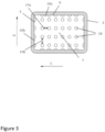
- Figure 3 shows a top view of a box body 3.
- the bottom wall 7 of the box body 3 comprises a plurality of substantially hemispherically shaped protrusions 18.
- the effect of the plurality of hemispherically shaped protrusions 18 is that they reduce the physical contact between the bottom wall 7 and the transported goods 15 and they reduce the contact between the bottom wall 7 and a cold or heat accumulator 16 positioned on the bottom wall 7.
- Figure 3 is shown also another embodiment where the plurality of hemispherically shaped protrusions 18 are aligned in rows in a lengthwise direction L of the bottom wall 7.
- a gap between two adjacent rows 19b and a gap between two adjacent half columns projecting from the end wall 10b are located substantially at the same location in the crosswise direction of the box body 3.
- the gaps 10b, 19b coincide at the junction of an end wall 5 and a bottom wall 7 the flow path for air from the upper part of the box body 3 continues along the bottom wall 7 horizontally.
- the box body 3, the half columns 9a-b and the plurality of substantially hemispherically shaped protrusions 18 comprise same material and form a unitary piece.
- the half columns 9a-b and the plurality of substantially hemispherically shaped protrusions 18 can also comprise separate elements.
- the half columns 9a-b can be formed with a plate comprising a plurality of half columns and the plate is attached to the box body 3.
- the half columns 9a-b can also comprise separate single pieces attached to the box body 3 individually.
- the hemispherically shaped protrusions 18 can be formed with a plate comprising a plurality of hemispherically shaped protrusions 18 and the plate is attached to the box body 3.
- the hemispherically shaped protrusions 18 can also comprise separate single pieces attached to the box body 3 individually.
- the half column 9a projecting from the side wall 4 projects from the side wall 4 by less than half its diameter.
- At least part of the half columns 9a projecting from the side walls 4 extend from the bottom wall 7 to the upper part of the box body 3.
- Figures 4-7 show different embodiments of positioning one or more separating partitions 11.
- the same separating partition 11 is positionable to form a supporting surface for one or more cold or heat accumulators 16, to form a supporting surface for the transported goods 15 in a lower part of the box body 3 and to form a separating wall for creating two horizontally adjacent spaces 20a-b.
- Examples of materials suitable for manufacturing material of a separating partition 11 are aluminium and plastics.
- substantially similar separating partitions separating partitions having similar outer dimensions, similar notching necessary to form the flow paths and necessary to surround the outer surface of the half column when the separating partition is installed above the bottom wall to the lower part of the box body 3.
- the separating partition 11 comprises lip parts 21 projecting from the edges 13. As the separating partition 11 is positioned to a lower part of the box body 3 the lip parts 21 touch the bottom wall 7 and support the separating partition 11 providing a flow path between the bottom wall 7 and the separating partition 11 as shown in Figures 4 , 6 and 7 . To allow an unobstructed air flow path the notch 12 of the separating partition 11 does not comprise a lip part 21.
- the separating partition comprises 11 notches 12 in three edges 13.
- the notches 12 of the separating partition 11 shown in Figures comprise a curved shape to surround the outer surface of the half column 9a-b when the separating partition is installed above the bottom wall 7 to the lower part of the box body 3.
- Figure 4 shows a box body 3 without a side wall comprising two separating partitions 11.
- the separating partitions 11 are assembled to the upper part of the box body 3 and to the lower part of the box body 3.
- the separating partition 11 assembled to the upper part of the box body 3 forms a supporting surface for one or more cold or heat accumulators 16.
- the separating partition 11 assembled to the lower part of the box body 3 is supported to the bottom wall 7 and forms a supporting surface for the transported goods 15 (not shown).
- the separating partition 11 prevents also the direct heat transfer by conduction from the bottom wall 7 to the transported goods 15.
- the separating partition 11 supported to the bottom wall 7 provides a separating wall preventing freezing or overheating of the transported goods 15.
- Figure 5 shows a box body 3 without a side wall proving a cross sectional view in the lengthwise direction L of the box body 3.
- the box body 3 comprises two separating partitions 11 assembled on the lower part of the box body 3.
- the separating partition 11 rests on the bottom wall 7 on the protrusions 18 the lips 21 facing upwards.
- the separating partitions 11 form a supporting surface for the transported goods 15 (not shown).
- Figure 6 shows a box body 3 without a side wall proving a cross sectional view in the lengthwise direction L of the box body 3.
- the box body 3 comprises two separating partitions 11 assembled on the lower part of the box body 3.
- the lip parts 21 of the separating partition 11 touch the bottom wall 7 and support the separating partition 11 providing a flow path between the bottom wall 7 and the separating partition 11.
- the separating partitions form a supporting surface for the transported goods 15. Further, if the one or more cold or heat accumulators 16 are positioned on the bottom wall 7, the separating partition 11 supported to the bottom wall 7 provides a separating wall preventing freezing or overheating of the transported goods 15.
- Figure 7 shows a thermally insulated transport box 1 where the box body 3 and the cover 2 are shown without side walls proving a cross sectional view in the lengthwise direction L of the thermally insulated transport box 1.
- Two of the separating partitions 11 are assembled on the lower part of the box body 3 and cover the bottom wall 7.
- the lip parts 21 of the separating partition 11 touch the bottom wall 7 and support the separating partition 11 providing a flow path between the bottom wall 7 and the separating partition 11.
- the separating partitions 11 form a supporting surface for the transported goods 15 (not shown). Further, if the one or more cold or heat accumulators 16 are positioned on the bottom wall 7, the separating partition 11 supported to the bottom wall 7 provides a separating wall preventing freezing or overheating of the transported goods 15.
- Two of the separating partitions 11 are assembled opposite each other to form an enclosure for one or more cold or heat accumulators 16.
- This enclosure comprising two separating partitions 11 forms a separating wall creating two in the lengthwise L of the box body 3 adjacent spaces 20a-b.
- the separating partition 11 is slidable in vertical direction between two adjacent half columns 9a projecting from a side wall 4. When assembled the separating partition 11 extends between the two opposing side walls 4 forming a separating wall whereby creating two adjacent spaces 20a-b to the box body 3.
- the half columns 9a projecting from the first side wall 4 support the first end of the separating partition and the half columns 9a projecting from the second side wall 4 support the second end of the separating partition 11.
- the half columns 9a keep the separating partition 11 in an upright position.
- An accumulator 16 comprising phase change material is advantageous in providing passive cooling or heating in the thermally insulated transport box 1.
- a phase change material with a high heat of fusion that through melting and solidifying at a certain temperature is capable of storing and releasing large amounts of energy.
- a cold accumulator and a heat accumulator suitable for the thermally insulated transport box 1 comprises a phase change material, which has its melting/solidifying temperature at a temperature range -50°C - +85°C.
- the thermally insulated transport box 1 can comprise cold accumulators 16 comprising phase change material, which have different melting/solidifying temperatures.
- the thermally insulated transport box 1 can also comprise heat accumulators 16 comprising phase change material, which have different melting/solidifying temperatures.
- FIG. 7 shown arrangement comprises two adjacent spaces 20a-b.
- the temperature of the first space 20a can be 5°C-+35°C higher than the temperature of the second space 20b. This can be achieved by providing cold/heat accumulators 16 having higher melting/solidifying temperatures above and below the first space 20a and providing cold/heat accumulators having lower melting/solidifying temperatures above and below the second space 20b.
- the cold or heat content of a thermally insulated transport box 1 depends on the amount of filling and the thermal capacity of the filling inside the box.
- the shape of the interior face of the thermally insulated transport box 1 provides a substantially rectangular shaped packing space.
- the substantially rectangular shaped packing space allows an effective use of a packing space thus providing a high filling ratio and a large carrying capacity. It allows also an easier packing operation that saves time.
- the arranged cold air circulation within the thermally insulated transport box together with the reduced heat transfer by conduction between the box body 3 and the transported goods 15 results in a reduced thickness of the box body 3.
- This increases capacity inside the box. Therefore, the thermally insulated transport box 1 requires less space to transport a given volume of goods making more efficient use of transport volume.
- the reduced thickness of the box body 3 also reduces the weight of the thermally insulated transport box, which is important when the box 1 is carried by a human.
- the separating partitions 11 within the thermally insulated transport box 1 prevent a direct contact of a cold accumulator 16 and the transported goods 15 thus preventing a thermal shock.
- the use of an accumulator 16 comprising phase change material having an operating temperature at a range +2°C-+8°C also prevents freezing.
- the phase change material has a melting temperature at a temperature range -2°C -0°C.
- the thermally insulated transport box may comprise one or more partition walls 22.
- the partition wall 22 is a separate part and its end is slidable between adjacent half columns 9a projecting from a side wall 4. When assembled the partition wall 22 extends between the two opposing side walls 4 creating two adjacent spaces.
- the half columns 9a projecting from the first side wall 4 support the first end of the partition wall 22 and the half columns 9a projecting from the second side wall 4 support the second end of the partition wall 22.
- the half columns 9a keep the partition wall in an upright position.
- the partition wall 22 is made of plate material, e.g. expanded polypropylene (EPP), for instance.
- the thermally insulated transport box 1 may comprise one or more partition walls 22,22b which is formed from a cold accumulator or a heat accumulator A1,A2.
- the partition walls 22,22b being a cold or heat accumulators may be used in the thermally insulated transport box 1 instead of a separating partitions 11, or together with one or more separation partitions 11.
- Alternative types of partition walls 22,22b are shown in Figures 9 and 15-24 .
- the thermally insulated transport box 1 may comprise a partition wall 22 comprising a cold accumulator or a heat accumulator 16, and the cold accumulator or the heat accumulator 16 comprises projecting parts 27 at least on one side surface.
- An example of the partition wall 22 comprising a cold accumulator or a heat accumulator 16 is shown in Figure 9 .
- the cold or heat accumulator 16 forming a partition wall 22 preferably comprises projecting parts 27 on its outer surface.
- the projecting parts 27 can be arranged on a one side surface only, or on the both side surfaces. If the projecting parts 27 are arranged to both of the side surfaces then preferably the projecting parts 27 comprise different sizes and positions depending on the side surface.
- a first side surface comprises projecting parts 27, which are higher than the projecting parts 27 comprised in a second side surface.
- the projecting parts 27 comprised in a second side surface have a height of 40-60% of the height of the projecting parts 27 of the first side surface.
- the projecting parts 27 of the first and second side surfaces have preferably different locations such as when two accumulators used for forming a partition wall 22 are stacked with a first side of surface of the first accumulator facing a second side surface of the second accumulator the projecting parts 27 of the accumulators touch each other at least partially such that an air flow path is formed between the partition walls 22.
- the air flow path increases the heat transfer between the partition walls 22 and the ambient air when stacked.
- the cold accumulator or the heat accumulator comprises a phase change material inside, e.g. a liquid polymere.
- the thermally insulated transport box 1 may also comprises a continuous temperature monitor to record the temperature of a thermally insulated transport box.
- the temperature monitoring is preferably made by a real-time monitoring device 23 capable of sending data wireless to a receiver.
- the receiver may be a network server or a cloud, for instance.
- the thermally insulated transport box 1 may also comprise a releasable display on its outer surface for convenience.
- the temperature monitoring device 23 is preferably attached to a separating partition 11 comprising a mounting tray 24 for the temperature monitoring device 23, or to a partition wall 22 comprising a mounting tray 24 for the temperature monitoring device 23.
- the temperature monitoring device 23 can also be in a close vicinity of the transported goods 15 during the transportation.
- the effect of attaching the temperature monitoring device 23 to a separating partition 11 or to a partition wall 22 supporting a cold accumulator or a heat accumulator 16 is that it provides information on the change of the temperature inside the thermally insulated transport box 1 before the change reaches the transported goods 15.
- the thermally insulated transport box 1 may also comprise a separate moisture-absorbing member.
- the moisture-absorbing member can comprise a moisture absorbing polymer mat, for instance.
- the moisture-absorbing member is preferably positioned on the bottom wall 7, or it is positioned to surround the transported goods 15.
- FIG. 8 shows an arrangement in a thermally insulated transport box 1.
- the thermally insulated transport box 1 comprises a cover 2 and a box body 3.
- the thermally insulated transport box 1 is portable and comprises fixing points 25 for a carrying member 26.
- the carrying member is handles provided at both end walls 5 of the box body 3.
- the lower part of the box body 3 comprises two separating partitions 11 positioned parallel above the bottom wall 7 and supported by the lip parts 21 touching the bottom wall 7.
- the separating partitions 11 support the transported goods 15 positioned in the box body 3.
- the separating partitions 11 form a lower surface in the box body 3.
- the upper part of the box body 3 comprises a separating partition 11 and a partition wall 22 formed from a cold accumulator or a heat accumulator.
- the separating partition 11 and the partition wall 22 are supported by the half columns of the side walls and end walls.
- the separating partition 11 and a partition wall 22 form an upper surface in the box body 3.
- the upper surface may comprise also two separating partitions 11.
- the space between the lower surface and the upper surface inside the box body 3 is split into two spaces 20a-b by means of a partition wall 22.
- the partition wall 22 comprises two partition walls 22 laid together.
- the partition wall 22 is formed from a cold accumulator or a heat accumulator.
- the spaces 20a-b are on the same horizontal level.
- Each space 20a-b comprises transported goods 15.
- the separating partition 11 comprises a mounting tray 24 for a temperature monitoring device 23.
- the partition walls 22 formed from cold or heat accumulators comprise phase change material.
- the together laid cold or heat accumulators forming the partition wall 22 in the crosswise direction w of the box body 3 have different melting/solidifying temperatures.
- the arrangement comprises a cold or heat accumulator laid on the separating partition 11 on the upper part of the box body 3 (not shown).
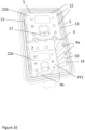
- Figures 10-13 show an embodiment where the thermally insulated transport box 1 comprises one or more partition walls 22b where a cold or heat accumulator A1,A2 is forming the partition wall 22b.
- the partition wall 22b i.e. the cold or heat accumulator A1,A2
- the partition wall 22b is supported by the half columns 9a-b.
- the partition wall 22b rests on the ends of the half columns 14. At least part of the notches 12 in the opposing edges 13 of the partition wall 22b align with gaps 10a between the half columns 9a projecting from the side wall 4 to form an air flow path.
- the same partition wall 22b is positionable between a gap 10a between adjacent half columns 9a to form a separating wall for creating two horizontally adjacent spaces 20c-d in the lengthwise direction L of the box body 3 as shown in Figure 11 .
- the inner surface of the side wall 4 comprises half columns along the length of the side wall 4.
- the partition wall 22,22b and/or the separating partition 11 can then be positioned to the gap 10 between the half columns 9a to any location in the lengthwise direction L of the thermally insulated transport box 1.
- the length of the created spaces can then be adjusted based on the dimensions of the transported goods 15.
- the cold or heat accumulator A1,A2 forming a partition wall 22b comprises a container C1 for phase-change material, said container comprising a front face FF1, a back face BF1 on the rear side of the container C1 and side ends SE1-SE4 between the front face FF1 and the back face BF1.
- the cold or heat accumulator A1 on front face FF1 and on the back face BF1 comprises protrusions PR111-PR113, PR121-PR123 and nests N111-N113, N121-N123, said protrusions PR111-PR113 of the accumulator A1 being arranged to be coupled with corresponding nests N221-N223 of an another accumulator A2, and said nests N111-N113 of the accumulator A1 being arranged to be coupled with corresponding protrusions of said another accumulator A2 so as to form a use-mode where the face FF1 of the container C1 of the accumulator A1 is arranged to be against the face BF2 of said another accumulator A2.
- two cold or heat accumulators A1,A2 are provided in one gap 10a between adjacent half columns 9a, and the two cold or heat accumulators A1,A2 are arranged in a use-mode where the front face FF1 of the accumulator A1 is arranged to be against the back face BF2 of another accumulator A2.
- the created tight stack of cold or heat accumulators A1,A2 is able to keep the stored cold or stored heat over a longer time.
- Figure 12 shows two partition walls 22b positioned side-by-side on the bottom wall 7.
- the partition wall 22b i.e. the cold or heat accumulator, comprises notches 12 in all edges 13
- the number and the size of the notches 12 varies depending on the edge 13.
- the notches 12 which are to be positioned to form an air flow path from the upper part of the box 1 along the end wall 5 can be smaller than the notches 12 which are positioned to surround the half columns 9b of the end walls 5 at the lower part of the box 1.
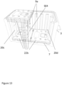
- the arrangement of Figure 13 comprises a plurality of cold or heat accumulators forming the partition walls 22b.
- Two partition walls 22b are positioned side-by-side on the bottom wall 7 to cover the bottom wall 7.
- Two partition walls 22b are provided in one gap 10a between adjacent half columns 9a, and the cold or heat accumulators forming the partition walls 22b are arranged in a use-mode.
- the partition walls 22b arranged upright to the gap 10a are supported by the partition walls 22b positioned side-by-side on the bottom wall 7, i.e. a side end SE4 of the cold or heat accumulator arranged upright is against the face of the cold or heat accumulator positioned on the bottom wall 7.
- the opening 6 is covered with a set of two partition walls 22b arranged one above the other and a further partition wall 22b.
- the set of two partition walls 22b comprises two cold or heat accumulators arranged in a use-mode.
- the further partition wall 22b is positioned side-by-side with the set of two partition walls 2b to cover the opening 6.
- the further partition wall 22b can comprise one cold or heat accumulator or a set of partition walls 22b comprising two cold or heat accumulators arranged in a use-mode.
- the further partition wall 22b is omitted from the Figure 13 for a sake of clarity.
- the shown arrangement in Figure 13 provides a transport arrangement for transported goods where the transported goods require different temperature ranges during the transport.
- the cold or heat accumulators are cold accumulators
- the cold accumulators positioned on the bottom wall prevent the heat transferred through the bottom to reach the transported goods.
- the cold accumulators positioned upright provide separate spaces within the box. The temperature range in the spaces can be adjusted by choosing cold accumulators comprising different melting temperatures to the lower and upper part of the box as well as to the upright partition wall.
- the cold accumulators positioned to cover the opening provide a downwards flowing cold air flow along the formed air flow path.
- Figure 14 shows a thermally insulated transport box showing the outer surface of the bottom wall 7 of the box body 3 and an outer upper surface of the cover 2.
- the outer upper surface of the cover 2 comprises extending portions 28 and the outer surface of the bottom wall 7 comprises recesses 29.
- the extending portions 28 of the cover 2 are arranged to be coupled with corresponding recesses 29 of outer surface of the bottom wall 7. If two insulated thermal transport boxes 1 are stacked one above the other the coupling provides support against transversal movement.
- the extending portions 28 are preferably flat and shallow.
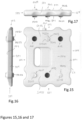
- partition wall 22b which is a cold or heat accumulator, is shown in Figures 15-24 and described in detail below.
- a accumulator A1 such as cold accumulator A1 comprising a container C1 for phase-change material PCM.
- PCM can be or contain water, gel, glycol, ammonium, paraffin or powder, for example.
- the material has an ability the get frozen and to melt from the frozen state.
- the material inside the container has ability to store heat and to release it.
- container C1 is a plastic container.
- cold or heat accumulator A1, A2 comprises notches 12 in its opposing edges 13.
- the cold or heat accumulator A1,A2 i.e. the partition wall 22b
- the cold or heat accumulator A1,A2 is supported by the half columns 9a-b.
- the cold or heat accumulator A1,A2 rests on the ends of the half columns 14.
- At least part of the notches 12 align with gaps 10a between the half columns 9a projecting from the side wall 4 to form an air flow path.
- the notches 12 of the cold or heat accumulator A1,A2 shown in Figures 15-24 comprise a curved shape to surround the outer surface of the half column 9a-b when the cold or heat accumulator A1,A2 is installed above the bottom wall 7 to the lower part of the box body 3.
- the cold or heat accumulator A1,A2 is slidable in vertical direction between two adjacent half columns 9a projecting from a side wall 4.
- the cold or heat accumulator A1,A2 extends between the two opposing side walls 4 forming a separating wall whereby creating two adjacent spaces 20c-d to the box body 3.
- the half columns 9a projecting from the first side wall 4 support the first end of the cold or heat accumulator A1,A2 and the half columns 9a projecting from the second side wall 4 support the second end of the cold or heat accumulator A1,A2.
- the half columns 9a keep the cold or heat accumulator A1,A2 in an upright position.
- a tight stack i.e. the face of the container of the accumulator is arranged to be against the face of another accumulator, comprising two stacked cold or heat accumulators fits between two adjacent half columns.
- the air cools around the cold or heat accumulator A1,A2, i.e. the partition wall 22b, it flows downwards along the formed flow path through the opening provided by the notch 12 and a gap 10 between two adjacent half columns 9a,b and further down along the gap between two adjacent half columns 10.
- the container C1 of the first accumulator A1 comprises a front face FF1, a back face BF1 on the rear side of the container C1 and side ends SE1-SE4 between the front face FF1 and the back face BF1.
- the container C1 On the front face FF1 and on the back face BF1, the container C1 comprises protrusions and nests.
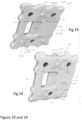
- protrusions PR111-PR113 On the front FF1 face of the container C1, there are three protrusions PR111-PR113, so that protrusions PR111, PR112 are on the first (in figures 15 and 18 the lower) surface area SA111 and a third protrusion PR113 is on the second (in figures 15 and 18 the upper) surface area SA112. Also, there are three nests (recesses) , so nests N111-N112 are on the second surface are a SA112 and a third nest N113 is on the first surface area SA111.
- FIG 19 showing the back (rear) face BF1 of the accumulator A1: Correspondingly in the back (rear) face BF1 of the container C1 of the first accumulator A1, there are three protrusions PR121-PR123, so that protrusions PR121, PR122 are on the second (in fig. 19 the lower) surface area SA122 of the back face BF1 and a third protrusion PR123 is on the first (in fig. 19 the upper) surface area SA121 of the back face BF1.
- nests N121-N123 there are three nests (recesses) N121-N123, so nests N121-N122 are on the first surface area SA121 of the back face BF1 of the accumulator A1 and a third nest N123 is on the second surface area SA122 of the back face BF1 of the accumulator A1.
- the front face FF2 of the accumulator A2 is shown in the left side of the figure 21
- the back (rear) face BF2 of the accumulator A2 is shown in the upper part of figures 20 and 22 . Therefore, regarding the protrusions and nest, on the front face FF2 of the container C2 of the second accumulator A2, there are three protrusions PR211-PR213, so that protrusions PR211, PR212 are on the first (in figure 21 lower) surface area SA211 and a third protrusion PR213 is on the second (in figure 21 the upper) surface area SA212. Also, on front face FF2 of accumulator A2 there are three nests (recesses) N211-N213, so nests N211-N212 are on the second surface area SA212 and a third nest N213 is on the first surface area SA211.
- nests N221-N223 there are three nests (recesses) N221-N223, so nests N221-N222 are on the first surface area SA221 of the back face BF2 of the accumulator A2 and a third nest N223 is on the second surface area SA222 of the back face BF2 of the accumulator A2.
- protrusions PR111-PR113 of accumulator A1 are arranged to be coupled with the nests N221-N223 of the accumulator A2, and the nests N111-N113 of the accumulator A1 are arranged to be coupled with the corresponding protrusions PR221-PR223 of accumulator A2, so as to form a use-position where the face of the container of the freeze accumulator A1 is arranged to be against the face of said another accumulator A2.
- face of the container C2 of the freeze accumulator A2 is arranged to be against the face of the container C1 of accumulator A1 and other face of accumulator A2 is against the face of the accumulator A3.
- "use-position” refers to a tight stack of accumulators that keeps the coolness/coldness more efficiently because the frozen freeze accumulators are tightly combined without gaps. Referring to figures 20-21 , this suitable relative position of accumulators A1, A2 can be reached by stacking accumulator A2 on top of accumulator A1 so that protrusion PR221 meets nest N111, protrusion PR222 meets nest N112, protrusion PR223 meets nest N113.
- protrusions PR111-PR113 of accumulator A1 meet the nests N221-N223 of the accumulator A2. Similar tight/gapless combination of accumulators A1, A2 can be done by just putting accumulator A2 of fig. 16 on top of accumulator fig 15 .
- the accumulators A1-A3 are arranged in such way that bottom face of an accumulator is against the front face of the next/parallel accumulator. For example, bottom face BF2 of the second accumulator A2 is against the front face FF1 of the first accumulator A1, and bottom face BF3 of the third accumulator A3 is against the front face FF2 of the second accumulator A2.
- the protrusions and nests are arranged in groups in such way that first group, which is at the first surface area SA111 of the respective face FF1 of the container C1, comprises at least three members including at least two protrusions PR111, PR112 and at least one nest N113. Additionally, the second group, which is at the second surface area SA112 of the respective face FF1 of the container C1, comprises at least three members including at least two nests N111, N112 and at least one protrusion PR113.
- first group which is at the first surface area SA111 of the respective face FF1 of the container C1
- the second group which is at the second surface area SA112 of the respective face FF1 of the container C1 comprises at least three members including at least two nests N111, N112 and at least one protrusion PR113.
- the protrusions and nests are arranged in groups in such way that second group, which is at the second surface area SA122 of the respective back face BF1 of the container C1, comprises at least three members including at least two protrusions PR121, PR122 and at least one nest N123. Additionally, the first group, which is at the first surface area SA121 of the respective face BF1 of the container C1, comprises at least three members including at least two nests N121, N122 and at least one protrusion PR123.
- the back face BF2 of the accumulator A2 would be set against front face FF1 of accumulator A1.
- the two nests N221, N222 and one protrusion PR223 locating at the first surface area SA221 of the back face BF2 of the accumulator A2 are arranged to engage their counterparts so two protrusions PR111, PR112 and one nest N113 locating at the first surface area SA111 of the front face FF1 of the accumulator A1. That would be the use-position so a tight stack without gap between the accumulators because the tight stack is able to keep the stored cold (or stored heat) over longer time.
- the accumulator A2 shown figs. 20-21 would first be turned/rotated 180 degrees around the vertical (longitudinal) axis of the accumulator A2, and because of that then the front face FF2 (shown in left side of fig. 21 ) of accumulator A2 would be arranged against the front face FF1 of the accumulator A1.
- Air gap - mode refers to both the to be freezed mode and the to be heated mode.
- front face FF1 of accumulator A1 is facing (with a gap G1) front face FF2 of next parallel accumulator A2 (or bottom face BF2 of accumulator A2 facing, with a gap G2 bottom face BF3 of accumulator A3), but instead the front face FF1 of the accumulator A1 would be facing (with a gap) back face (lower face) BF2 of the accumulator A2, and front face FF2 of the accumulator A2 would be facing (with a gap) back face (lower face) BF3 of the accumulator A3.
- the interrelation between accumulators A2 and A3 is as disclosed regarding the interrelation between accumulators A1 and A2.
- the freezing gap between accumulators A2 and A3 is marked with G2.
- the height of the gap is preferably at least 10mm.
- the height of the protrusions, like PR111-PR113, PR211-PR223, is prefearably at least 6mm.
- the above mentioned turning (compared to use-position of fig. 23 ) of the accumulator can one or more of the following: rotating 180 degrees in planar way (so not rotating around the axis of the accumulator) or alternatively rotating/flipping 180 degrees around longitudinal axis of the accumulator.
- Longitudional axis is running in the vertical direction in figures 15-16 and towards the viewer in figures 23-24 , and it is transversal compared to direction of group of protrusions/nest at area SA111 having protrusion PR111, nest N113 and protrusion PR112, and the longitudional axis is also transversal compared to direction of group of nests/protrusion at area SA112 having nest N111, protrusion PR113 and nest N112.
- protrusions and nests are arranged in groups in such way that first group, which is at the first surface area SA111 of the respective face FF1 of the container C1, comprises at least three members including at least two protrusions PR111, PR112 and at least one nest N113. Additionally, the second group, which is at the second surface area SA112 of the respective face FF1 of the container C1, comprises at least three members including at least two nests N111, N112 and at least one protrusion PR113. Referring to this, there are the following preferred embodiments.
- the first group located on said first surface area SA111 and the second group located on said second surface area SA112 are next to different side ends SE1-SE4 of the container.
- the first group locating on said first surface area SA111 and second group locating on said second surface SA112 area are next to opposing side ends SE1, SE3 of the container C1.
- the first group locating on said first surface area SA111 and second group locating on said second surface area SA112 are parallel with each other. In other words the line/row comprising protrusion PR111, nest N113 and protru-sion PR112 is parallel with the line/row comprising nest N111, protrusion PR113 and nest N112.
- the first group locating on said first surface area SA121 at back face BF1 and second group locating on said second surface SA122 area are next to opposing side ends SE1, SE3 of the container C1.
- the first group locating on said first surface area SA121 at back face BF1 and second group locating on said second surface area SA122 are parallel with each other.
- the line/row comprising protrusion PR121, nest N 123 and protrusion PR122 is parallel with the line/row comprising nest N121, protrusion PR123 and nest N122.
- the accumulator A1 is such that at positions where on the front face FF1 of the container there are protrusions like PR111-PR113, there are nests N121, N122, N123 on the back face BF1 of container C1. And correspondingly, at positions where on the front face FF1 of the container C1 there are nests N111-N113, there are protrusions PR121, PR122, PR123 on the back face BF1 of container C1.
- one or more protrusion such as PR111, PR113 comprise a support structure SS111, SS113 for positioning the protrusion of the accumulator A1 against the protrusion of another accumulator A2, so as the create support against transversal movement of the accumulators A1, A2.
- at least three protrusions (on each face), suh as PR111-PR113, PR121-PR123 comprise support structure thereof.
- the protrusions PR111-PR113 have protrusion-specific support structure SS111-SS113 having different shape than the other support structure in one or more protrusion PR111-PR113.
- the back face BF1 there are support structures SS121-SS123 on the protrusions PR121-PR123.
- the support structure SS111 is a wall of the hollow space (recess) at the end face of the protrusion PR111 at front face FF1.
- support structure SS121 is a wall of the hollow space (recess) at the end face of the protrusion PR121 at the back face BF1.
- the protrusions of the second accumulator A2 have support structures SS221-SS223, SS211-SS213.
- the support structures SS221-SS223 are at the end face of the protrusions PR221-PR223 on the back face BF2 of the accumulator A2, as shown in upper part of figure 20 .
- the support structures SS211-SS213 are at the end face of the protrusions PR211-PR213 on the front face FF2 of the accumulator A2, as shown in left part of fig. 21 .
- Support structure SS211 on protrusion PR211 in fig. 21 and support structure SS221 on protrusion PR221 are like the earlier mentioned recess-walls SS111 and SS121 in fig 19 .
- recess-wall SS111 at the end face of protrusion PR111 at front face FF1 of accumulator A1 is regarded as first type of positioning structure
- the curved shape SS112 of protrusion PR112 can be regarded as second type of support structure for positioning, because it co-operates with recess-wall SS221 of protrusion PR221 at accumulator A2.
- third type of support structure is discussed in the following.
- third type of support structure is according to an embodiment, wherein one or more support structure is a step structure SS113 comprising a lower step SS113L and a higher step SS113H at the end face of the protrusion PR113.
- the second ac-cumulator A2 comprises step structure SS223 that is at the end face of the protrusion PR223, and likewise this step structure SS223 comprises lower step SS223L and a higher step SS223H at the end face of the protrusion PR223.
- the higher step S113H at protrusion PR113 at the accumulator A1 is coupled (engaged, connected, set against) with the lower step SS213L that is at the protrusion PR213 at the front face FF2 of second accumulator A2.
- the lower step S113L at protrusion PR113 at the accumulator A1 is coupled (connected, set against) with the higher step SS213H that is at the protrusion PR213 at the front face FF2 of the second accumulator A2.
- the "higher” and “lower” are to be understood as compared to the surface of the container, not to understood as which step in higher from the ground.
- the protrusion PR113 in the second group, which is at the second surface area SA112 of the respective face FF1 of the container C1, the protrusion PR113, having a step structure SS113H, SS113L as a support structure SS113, is located between the two nests N111, N112. Furthermore, in first group, which is at the first surface area SA111 of the respective face FF1 of the container C1, the nest N113 is between the two protrusions PR111, PR112. Similar principle is at the mirror-like back side BF1 of the accumulator A1.
- protrusions provide an air gap in relation to bottom wall or other wall of the box into which box the freeze accumulator is inserted.
- SIL1 and SIL2 refer to sealed/closed input that has been used when filling the containers C1, C2 with phase-change material.
- the disclosed embodiments relate to accumulator where the basic shape of the accumulator and especially the setting, formed from the location of groups having protrusions/nest or nests/protrusion, is rectangular. However a square-based form is also possible, and in that case there is a group of protrusions/nest or a group of nests/protrusion that is transversely (about 90 degrees) oriented compared to other group having nests/protrusion or protrusions/nest. In that case, for an accumulator, a planar rotation of only about 90 degrees is suitable for creating the air gap - mode (for freezing or heating) where three protrusions of an accumulator meet the three protrusions of another accumulator. This kind of transversal group could be vertical i.e longitudional in figure 15 , and be next to side edges SE1 and/or SE4.
- the element of the invention is that on same side (same face) of the accumulator there are two coupling element groups, next to edges SE1, SE3, at different surface areas SA111, SA112 on face FF1, those groups each having op-posed type of coupling elements (protrusion, nest) within a group and also when compared to the other group on that same face FF1.
- Group at area SA111 has two protrusions PR111, PR112 and a nest N113
- group at surface area SA112 has two nest N111, N112 and a protrusions PR113.
- the above refers also to that at positions where on the front face FF1 of the container there are protrusions PR111-PR113, there are nests N121-N123 on the back face BF1 of container C1, and correspondingly, at positions where on the front face FF1 of the container C1 there are nests N111-N113, there are pro-trusions PR121-PR123 on the back face BF1 of container C1.
- thermally insulated transport box examples include expanded polypropylene (EPP), expanded polystyrene (EPS) or polyurethane (PUR).
- EPP expanded polypropylene
- EPS expanded polystyrene
- PUR polyurethane
- the outer surface of the thermally insulated transport box 1 can also be painted with a heat reflective paint in order to reduce ambient heat load.
- a coating can be applied to the outer surface of the thermally insulated transport box 1 to prevent the box from denting and scratching. The coating can also reduce ambient heat load by reflecting.
- an antimicrobial coating can be applied to the interior face or/and the outer surface of the thermally insulated transport box.
- perishable foodstuffs may temporarily be sold and stored in an isolated container containing a lid closing the container when the container includes a cold accumulator, or even without a cold accumulator if the storage temperature remains below a legal maximum due to the existing ambient temperature.
- Perishable foods are those likely to spoil, decay or become unsafe to consume if not kept at chill temperatures below a legal maximum. Examples of perishable foods are meat, poultry, fish and dairy products. Typical legal maximum temperature for perishable foods is 0-8°C.
- the thermally insulated transport box 1 of the can be used for temporary storing of perishable foodstuffs.
- the phase change material has a melting temperature at a temperature range -2°C - 2°C.
Landscapes
- Engineering & Computer Science (AREA)
- Health & Medical Sciences (AREA)
- Mechanical Engineering (AREA)
- Animal Behavior & Ethology (AREA)
- Life Sciences & Earth Sciences (AREA)
- General Health & Medical Sciences (AREA)
- Public Health (AREA)
- Veterinary Medicine (AREA)
- Pharmacology & Pharmacy (AREA)
- Hematology (AREA)
- Chemical & Material Sciences (AREA)
- Combustion & Propulsion (AREA)
- Physics & Mathematics (AREA)
- Thermal Sciences (AREA)
- General Engineering & Computer Science (AREA)
- Packages (AREA)
Claims (10)
- Wärmeisolierte Transportkiste, wobei die wärmeisolierte Transportkiste (1) umfassteine Abdeckung (2) undeinen Kistenkörper (3), wobei der Kistenkörper (3) Seitenwände (4), Stirnwände (5), eine Öffnung (6) und eine Bodenwand (7) umfasst, wobeidie Innenoberflächen der Seitenwände (4) Halbsäulen (9a) umfassen, die von der Seitenwand (4) vorstehen, die Innenoberflächen der Stirnwände (5) Halbsäulen (9b) umfassen, die von der Stirnwand (5) vorstehen, und die Halbsäulen (9a-b) vertikal entlang der Seitenwände (4) und entlang der Stirnwände (5) verlaufen, unddie wärmeisolierte Transportkiste (1) mindestens eine Zwischenwand (22, 22b) umfasst, die Einkerbungen (12) in ihren gegenüberliegenden Kanten (13) umfasst, und wenn die Zwischenwand (22, 22b) positioniert ist, um mindestens einen Teil der Öffnung (6) abzudecken, die Zwischenwand (22, 22b) von den Halbsäulen (9a-b) getragen wird, und mindestens ein Teil der Einkerbungen (12) mit Lücken (10a) zwischen den Halbsäulen (9a) ausgerichtet ist, die von der Seitenwand (4) vorstehen, um einen Luftstromweg zu bilden, und dieselbe Zwischenwand (22, 22b) zwischen benachbarten Halbsäulen (9a) positionierbar ist, um eine Trennwand zur Schaffung zweier horizontal benachbarter Räume (20a-d) zu bilden, und ein Kälte- oder Wärmespeicher (A1, A2) die Zwischenwand (22,22b) bildet.wobei der Kälte- oder Wärmespeicher (A1, A2) einen Behälter (C1) für Phasenwechselmaterial umfasst, wobei der Behälter eine Vorderseite (FF1), eine Rückseite (BF1) auf der Rückseite des Behälters (C1) und Seitenenden (SE1-SE4) zwischen der Vorderseite (FF1) und der Rückseite (BF1) umfasst, unddass der Speicher (A1) auf der Vorderseite (FF1) und auf der Rückseite (BF1) Vorsprünge (PR111-PR113, PR121-PR123) und Nester (N111-N113, N121-N123) umfasst, dadurch gekennzeichnet, dass die Vorsprünge (PR111-PR113) des Speichers (A1) angeordnet sind, um mit entsprechenden Nestern (N221-N223) eines anderen Speichers (A2) gekoppelt zu werden, und die Nester (N111-N113) des Speichers (A1) angeordnet sind, um mit entsprechenden Vorsprüngen des anderen Speichers (A2) gekoppelt zu werden, um einen Verwendungsmodus zu bilden, bei dem die Seite (FF1) des Behälters (C1) des Speichers (A1) angeordnet ist, um an der Seite (BF2) des anderen Speichers (A2) anzuliegen,auf beiden, der Vorderseite (FF1) und der Rückseite (BF1) des Kälte- oder Wärmespeichers (A1,A2) die Vorsprünge und Nester in Gruppen angeordnet sind,sodass eine erste Gruppe, die sich im ersten Oberflächenbereich (SA111, SA121) der jeweiligen Seite (FF1; BF1) des Behälters (C1) befindet, mindestens drei Elemente umfasst, die mindestens zwei Vorsprünge (PR111, PR112; PR121, PR122) und mindestens ein Nest (N113; N123) beinhalten, unddass eine zweite Gruppe, die sich an der zweiten Oberfläche (SA112; SA122) der jeweiligen Fläche (FF1; BF1) des Behälters befindet, mindestens drei Elemente umfasst, die mindestens zwei Nester (N111, N112; N121, N122) und mindestens einen Vorsprung (PR113; PR123) beinhalten,sodass, wenn der Speicher (A1) angeordnet ist, um sich im Vergleich zum anderen Speicher (A2) in einer gedrehten Position zu befinden, die Vorsprünge (PR111-PR113) des Speichers (A1) an den Vorsprüngen des zweiten Speichers (A2) angeordnet sind, um einen Luftspaltmodus zu bilden, wobei die Seite (FF1) des Speichers (A1) angeordnet ist, um von der Seite (FF2) des anderen Speichers (A2) entfernt zu sein und dadurch ein Luftspalt (G1) zwischen der Seite (FF1) des Speichers und der Seite (FF2) des anderen Speichers (A2) bereitzustellen,und sodass sich auf der Seite (FF1; BF1) des Behälters (C1) die auf dem ersten Oberflächenbereich (SA111, SA121) befindliche erste Gruppe und die auf dem zweiten Oberflächenbereich (SA112; SA122) befindliche zweite Gruppe neben unterschiedlichen Seitenenden (SE1-SE4) des Behälters (C1) befinden.
- Wärmeisolierte Transportkiste nach Anspruch 1, dadurch gekennzeichnet, dass die wärmeisolierte Transportkiste (1) weiter mindestens eine Zwischentrennung (11) umfasst, die Einkerbungen (12) in ihren gegenüberliegenden Kanten (13) umfasst, und wenn die Zwischentrennung (11) positioniert ist, um mindestens einen Teil der Öffnung (6) abzudecken, die Zwischentrennung von den Halbsäulen (9a-b) getragen, und mindestens ein Teil der Einkerbungen (12) mit Lücken (10a) zwischen den Halbsäulen (9a) ausgerichtet ist, die von der Seitenwand (4) hervorstehen, um einen Luftstromweg zu bilden, und die gleiche Zwischentrennung (11) zwischen benachbarten Halbsäulen (9a) positionierbar ist, um eine Trennwand zur Schaffung zweier horizontal benachbarter Räume (20a-b) zu bilden.
- Wärmeisolierte Transportkiste nach einem der Ansprüche 1-2, dadurch gekennzeichnet, dass die Bodenwand (7) eine Vielzahl von im Wesentlichen halbkugelförmigen Vorsprüngen (18) umfasst.
- Wärmeisolierte Transportkiste nach Anspruch 3, dadurch gekennzeichnet, dass mindestens ein Teil der Vielzahl von im Wesentlichen halbkugelförmigen Vorsprüngen (18) in Reihen in Querrichtung (w) der Bodenwand (7) ausgerichtet ist und sich ein Spalt (19a) zwischen zwei benachbarten Reihen und ein Spalt (10a) zwischen zwei benachbarten Halbsäulen (9a), die von der Seitenwand (4) vorstehen, im Wesentlichen an der gleichen Stelle in Längsrichtung (L) des Kistenkörpers (3) befinden.
- Wärmeisolierte Transportkiste nach Anspruch 3, dadurch gekennzeichnet, dass der Kistenkörper (3), die Halbsäulen (9a-b) und die Vielzahl von im Wesentlichen halbkugelförmigen Vorsprüngen (18) ein gleiches Material umfassen und ein einheitliches Stück bilden.
- Wärmeisolierte Transportkiste nach einem der Ansprüche 1-5, dadurch gekennzeichnet, dass sich mindestens ein Teil der Halbsäulen (9a), die von den Seitenwänden (4) vorstehen, von der Bodenwand (7) bis zum oberen Teil des Kistenkörpers (3) erstreckt.
- Wärmeisolierte Transportkiste nach einem der Ansprüche 1-6, dadurch gekennzeichnet, dass die Halbsäule (9a), die von der Seitenwand (4) vorsteht, um weniger als die Hälfte ihres Durchmessers von der Seitenwand (4) vorsteht.
- Wärmeisolierte Transportkiste nach einem der Ansprüche 2-7, dadurch gekennzeichnet, dass dieselbe Trennwand (11) positionierbar ist, um eine Stützoberfläche für einen oder mehrere Kälte- oder Wärmespeicher (16) zu bilden, und um eine Stützoberfläche für die transportierten Güter (15) in einem unteren Teil des Kistenkörpers (3) zu bilden.
- Wärmeisolierte Transportkiste nach einem der Ansprüche 1-8, dadurch gekennzeichnet, dass, wenn die Zwischenwand (22,22b) an einem unteren Teil des Kistenkörpers (3) positioniert ist, die Einkerbungen (12) mit den Halbsäulen (9a) ausgerichtet sind, um die Halbsäulen (9a) zu umgeben.
- Wärmeisolierte Transportkiste nach einem der Ansprüche 2-9, dadurch gekennzeichnet, dass die Zwischentrennung (11) Lippenteile (21) umfasst, die von den Kanten (13) vorstehen, und wenn die Zwischentrennung (11) an einem unteren Teil des Kistenkörpers (3) positioniert ist, die Lippenteile (21) die Bodenwand (7) berühren und die Zwischentrennung (11) stützen, wodurch ein Luftstromweg zwischen der Bodenwand (7) und der Zwischentrennung (11) bereitgestellt wird.
Applications Claiming Priority (3)
| Application Number | Priority Date | Filing Date | Title |
|---|---|---|---|
| PCT/EP2017/079042 WO2019091581A1 (en) | 2017-11-13 | 2017-11-13 | Thermally insulated transport box |
| FI20185366A FI20185366A1 (en) | 2018-04-18 | 2018-04-18 | Accumulator for storage of cold or heat |
| PCT/FI2018/050828 WO2019092320A1 (en) | 2017-11-13 | 2018-11-12 | A thermally insulated transport box and an arrangement in a thermally insulated transport box |
Publications (3)
| Publication Number | Publication Date |
|---|---|
| EP3710377A1 EP3710377A1 (de) | 2020-09-23 |
| EP3710377A4 EP3710377A4 (de) | 2020-12-16 |
| EP3710377B1 true EP3710377B1 (de) | 2025-05-14 |
Family
ID=66438250
Family Applications (1)
| Application Number | Title | Priority Date | Filing Date |
|---|---|---|---|
| EP18877052.3A Active EP3710377B1 (de) | 2017-11-13 | 2018-11-12 | Wärmeisolierte transportkiste |
Country Status (7)
| Country | Link |
|---|---|
| US (1) | US11072482B2 (de) |
| EP (1) | EP3710377B1 (de) |
| JP (1) | JP2021502537A (de) |
| KR (1) | KR20200071129A (de) |
| CN (1) | CN111372867B (de) |
| FI (1) | FI3710377T3 (de) |
| WO (1) | WO2019092320A1 (de) |
Families Citing this family (10)
| Publication number | Priority date | Publication date | Assignee | Title |
|---|---|---|---|---|
| US20230182989A1 (en) * | 2019-06-24 | 2023-06-15 | Ifoodbag Ab | Method of delivering chilled goods |
| IL275977B2 (en) * | 2019-07-17 | 2024-04-01 | Rosenblum Reut | Sterile Apparatus for Rapid Cooling of Hot Water |
| DE102019213581A1 (de) * | 2019-09-06 | 2021-03-11 | BSH Hausgeräte GmbH | Lebensmittel-Aufnahmeschale mit spezifisch ausgebildeter Kühlakkuhalterung |
| US20210403224A1 (en) * | 2020-06-24 | 2021-12-30 | World Courier Management Limited | Packaging system for transporting temperature-sensitive products |
| CN112158451B (zh) * | 2020-10-21 | 2022-06-17 | 圆因(北京)生物医药科技有限公司 | 一种具有分层式冷气循环结构的疫苗试剂转移用冷冻箱 |
| US20230257185A1 (en) * | 2020-10-26 | 2023-08-17 | Pelican Biothermal, Llc | Passive thermally controlled shipping container and components thereof |
| DE202020107340U1 (de) * | 2020-12-17 | 2021-01-20 | Va-Q-Tec Ag | Isolationsbehälter für den temperaturgeführten Transport von pharmazeutischen Produkten |
| CN114963640B (zh) * | 2021-02-18 | 2024-05-24 | 内蒙古伊利实业集团股份有限公司 | 门组件及冷柜 |
| CN115583432B (zh) * | 2022-09-27 | 2023-04-25 | 国网湖北省电力有限公司直流公司 | 一种多功能直流控制保护板卡包装盒 |
| US20260022881A1 (en) * | 2024-07-20 | 2026-01-22 | University Of Connecticut | Cooler |
Family Cites Families (25)
| Publication number | Priority date | Publication date | Assignee | Title |
|---|---|---|---|---|
| US2137705A (en) * | 1936-04-20 | 1938-11-22 | Charles Leander Tiefry | Portable refrigerator or cooler |
| US3255607A (en) * | 1965-03-24 | 1966-06-14 | Lester E Bair | Thermal chests |
| JPS56118865U (de) * | 1980-02-14 | 1981-09-10 | ||
| DE3031176A1 (de) | 1980-08-18 | 1982-04-01 | Zorn, Edgar, 6300 Gießen | Kuehlakku mit einer kaeltespeicher- oder einer kaelte erzeugenden masse |
| US4441336A (en) | 1982-08-23 | 1984-04-10 | Plattner Industries, Inc. | Cooler having freeze bottle insert |
| JPH0142539Y2 (de) * | 1984-12-31 | 1989-12-12 | ||
| US4656840A (en) * | 1985-11-29 | 1987-04-14 | Gott Corporation | Container for freezable liquid |
| GB2282661B (en) | 1992-06-03 | 1996-02-07 | Kouwenberg Robert J C | An ice pack container |
| US5910162A (en) * | 1997-04-27 | 1999-06-08 | Paul Flum Ideas, Inc. | Product merchandising unit with variable/selectable product capacity |
| DE19907184A1 (de) * | 1999-02-19 | 2000-08-24 | Bsh Bosch Siemens Hausgeraete | Gefrierschrank |
| JP2000346514A (ja) * | 1999-06-08 | 2000-12-15 | Inoac Corp | 保冷箱及び蓄冷体付き保冷箱 |
| US6279744B1 (en) * | 2000-04-27 | 2001-08-28 | Chih-Hsin Yu | Tool kit structure |
| JP2002154582A (ja) * | 2000-11-16 | 2002-05-28 | Toho Kogyo Kk | 板状体搬送函体 |
| JP3850852B2 (ja) * | 2004-10-05 | 2006-11-29 | 俊郎 藤原 | 基板搬送用容器 |
| US20060174648A1 (en) | 2005-01-26 | 2006-08-10 | Gary Lantz | Insulated shipping container and method |
| GB2465376B (en) * | 2008-11-14 | 2012-11-28 | Tower Cold Chain Solutions Ltd | Thermally insulated reuseable transportation container |
| CN201314757Y (zh) | 2008-11-20 | 2009-09-23 | 海信科龙电器股份有限公司 | 一种果菜抽屉 |
| US20110098256A1 (en) | 2009-10-22 | 2011-04-28 | Hines Dixie J | Method for making and using a topical dermatological solution |
| KR101848960B1 (ko) | 2011-04-21 | 2018-04-13 | 벡톤 디킨슨 프랑스 | 의료 용기용 패키징 |
| GB201112661D0 (en) * | 2011-07-22 | 2011-09-07 | Softbox Systems Ltd | Container temperature control system |
| TWI507649B (zh) * | 2012-11-22 | 2015-11-11 | Ind Tech Res Inst | 蓄冷片 |
| DE102013003008B4 (de) * | 2013-02-23 | 2015-03-19 | delta T Gesellschaft für Medizintechnik mbH | Vollbluttransportsystem |
| JP2015193388A (ja) * | 2014-03-31 | 2015-11-05 | 積水化成品工業株式会社 | 保冷箱 |
| DE102014016463A1 (de) * | 2014-11-07 | 2016-05-12 | Rieber Gmbh & Co. Kg | Transportbox für Gastro-Norm-Behälter |
| KR101783021B1 (ko) | 2016-05-04 | 2017-09-28 | ㈜스페이스선 | 조립 가능한 모듈 타입 빗물 저장장치 |
-
2018
- 2018-11-12 EP EP18877052.3A patent/EP3710377B1/de active Active
- 2018-11-12 CN CN201880073053.2A patent/CN111372867B/zh active Active
- 2018-11-12 FI FIEP18877052.3T patent/FI3710377T3/fi active
- 2018-11-12 JP JP2020544163A patent/JP2021502537A/ja active Pending
- 2018-11-12 US US16/758,480 patent/US11072482B2/en active Active
- 2018-11-12 KR KR1020207015388A patent/KR20200071129A/ko not_active Ceased
- 2018-11-12 WO PCT/FI2018/050828 patent/WO2019092320A1/en not_active Ceased
Also Published As
| Publication number | Publication date |
|---|---|
| WO2019092320A1 (en) | 2019-05-16 |
| KR20200071129A (ko) | 2020-06-18 |
| US20200247602A1 (en) | 2020-08-06 |
| US11072482B2 (en) | 2021-07-27 |
| JP2021502537A (ja) | 2021-01-28 |
| EP3710377A4 (de) | 2020-12-16 |
| FI3710377T3 (fi) | 2025-08-14 |
| CN111372867B (zh) | 2022-08-26 |
| CN111372867A (zh) | 2020-07-03 |
| EP3710377A1 (de) | 2020-09-23 |
Similar Documents
| Publication | Publication Date | Title |
|---|---|---|
| US11072482B2 (en) | Thermally insulated transport box and an arrangement in a thermally insulated transport box | |
| US11572227B2 (en) | Thermally insulated shipping system for pallet-sized payload, methods of making and using the same, and kit for use therein | |
| US5669233A (en) | Collapsible and reusable shipping container | |
| US8938986B2 (en) | Modular system for thermally controlled packaging devices | |
| EP2374443B1 (de) | Passiv wärmegesteuerter Schüttgutversandcontainer | |
| EP3303176B1 (de) | Vorrichtung und verfahren zum transportieren von temperaturempfindlichem material | |
| US20190383546A1 (en) | Phase change material (pcm) belts | |
| AU2004257250B2 (en) | Insulated shipping containers | |
| US7866539B2 (en) | Container for transporting cooled goods | |
| US10618695B2 (en) | Contents rack for use in insulated storage containers | |
| GB2465376A (en) | Container with phase change material (PCM) units for maintaining constant temperature | |
| KR20180061230A (ko) | 냉각 운반 박스를 위한 보온 저장 셀 | |
| US20070295733A1 (en) | Shipping System and Container for Transportation and In-Store Maintenance of Temperature Sensitive Products | |
| US20170307278A1 (en) | Segmented container with multiple temperature zones | |
| US10619907B2 (en) | Refrigerated, thermally insulated, collapsible cover system, assembly and method of using to transport perishable products | |
| WO2019091581A1 (en) | Thermally insulated transport box | |
| GB2552821A (en) | An apparatus for preserving perishable items in transit or storage | |
| US12110167B2 (en) | Insulation container for temperature-controlled transport of pharmaceutical products | |
| US10955186B1 (en) | Refrigerated, thermally insulated, collapsible cover assembly and method of using to transport perishable products | |
| KR102634834B1 (ko) | 냉매팩의 모듈형 연결 구조체 | |
| JPH0627582Y2 (ja) | 保温保冷用コンテナ |
Legal Events
| Date | Code | Title | Description |
|---|---|---|---|
| STAA | Information on the status of an ep patent application or granted ep patent |
Free format text: STATUS: THE INTERNATIONAL PUBLICATION HAS BEEN MADE |
|
| PUAI | Public reference made under article 153(3) epc to a published international application that has entered the european phase |
Free format text: ORIGINAL CODE: 0009012 |
|
| STAA | Information on the status of an ep patent application or granted ep patent |
Free format text: STATUS: REQUEST FOR EXAMINATION WAS MADE |
|
| 17P | Request for examination filed |
Effective date: 20200423 |
|
| AK | Designated contracting states |
Kind code of ref document: A1 Designated state(s): AL AT BE BG CH CY CZ DE DK EE ES FI FR GB GR HR HU IE IS IT LI LT LU LV MC MK MT NL NO PL PT RO RS SE SI SK SM TR |
|
| AX | Request for extension of the european patent |
Extension state: BA ME |
|
| REG | Reference to a national code |
Ref country code: DE Ref legal event code: R079 Free format text: PREVIOUS MAIN CLASS: B65D0081380000 Ipc: F25D0003080000 |
|
| A4 | Supplementary search report drawn up and despatched |
Effective date: 20201118 |
|
| RIC1 | Information provided on ipc code assigned before grant |
Ipc: A61J 1/16 20060101ALI20201112BHEP Ipc: F25D 3/08 20060101AFI20201112BHEP Ipc: B65D 25/06 20060101ALI20201112BHEP Ipc: F25D 23/06 20060101ALN20201112BHEP |
|
| DAV | Request for validation of the european patent (deleted) | ||
| DAX | Request for extension of the european patent (deleted) | ||
| STAA | Information on the status of an ep patent application or granted ep patent |
Free format text: STATUS: EXAMINATION IS IN PROGRESS |
|
| 17Q | First examination report despatched |
Effective date: 20230118 |
|
| P01 | Opt-out of the competence of the unified patent court (upc) registered |
Effective date: 20230615 |
|
| GRAP | Despatch of communication of intention to grant a patent |
Free format text: ORIGINAL CODE: EPIDOSNIGR1 |
|
| STAA | Information on the status of an ep patent application or granted ep patent |
Free format text: STATUS: GRANT OF PATENT IS INTENDED |
|
| RIC1 | Information provided on ipc code assigned before grant |
Ipc: F25D 23/06 20060101ALN20241130BHEP Ipc: A61J 1/16 20060101ALI20241130BHEP Ipc: B65D 25/06 20060101ALI20241130BHEP Ipc: F25D 3/08 20060101AFI20241130BHEP |
|
| INTG | Intention to grant announced |
Effective date: 20241212 |
|
| GRAS | Grant fee paid |
Free format text: ORIGINAL CODE: EPIDOSNIGR3 |
|
| GRAA | (expected) grant |
Free format text: ORIGINAL CODE: 0009210 |
|
| STAA | Information on the status of an ep patent application or granted ep patent |
Free format text: STATUS: THE PATENT HAS BEEN GRANTED |
|
| AK | Designated contracting states |
Kind code of ref document: B1 Designated state(s): AL AT BE BG CH CY CZ DE DK EE ES FI FR GB GR HR HU IE IS IT LI LT LU LV MC MK MT NL NO PL PT RO RS SE SI SK SM TR |
|
| REG | Reference to a national code |
Ref country code: GB Ref legal event code: FG4D |
|
| REG | Reference to a national code |
Ref country code: CH Ref legal event code: EP |
|
| REG | Reference to a national code |
Ref country code: DE Ref legal event code: R096 Ref document number: 602018082008 Country of ref document: DE |
|
| REG | Reference to a national code |
Ref country code: IE Ref legal event code: FG4D |
|
| REG | Reference to a national code |
Ref country code: FI Ref legal event code: FGE |
|
| REG | Reference to a national code |
Ref country code: SE Ref legal event code: TRGR |
|
| REG | Reference to a national code |
Ref country code: NL Ref legal event code: MP Effective date: 20250514 |
|
| PG25 | Lapsed in a contracting state [announced via postgrant information from national office to epo] |
Ref country code: ES Free format text: LAPSE BECAUSE OF FAILURE TO SUBMIT A TRANSLATION OF THE DESCRIPTION OR TO PAY THE FEE WITHIN THE PRESCRIBED TIME-LIMIT Effective date: 20250514 Ref country code: PT Free format text: LAPSE BECAUSE OF FAILURE TO SUBMIT A TRANSLATION OF THE DESCRIPTION OR TO PAY THE FEE WITHIN THE PRESCRIBED TIME-LIMIT Effective date: 20250915 |
|
| REG | Reference to a national code |
Ref country code: LT Ref legal event code: MG9D |
|
| PG25 | Lapsed in a contracting state [announced via postgrant information from national office to epo] |
Ref country code: NO Free format text: LAPSE BECAUSE OF FAILURE TO SUBMIT A TRANSLATION OF THE DESCRIPTION OR TO PAY THE FEE WITHIN THE PRESCRIBED TIME-LIMIT Effective date: 20250814 Ref country code: GR Free format text: LAPSE BECAUSE OF FAILURE TO SUBMIT A TRANSLATION OF THE DESCRIPTION OR TO PAY THE FEE WITHIN THE PRESCRIBED TIME-LIMIT Effective date: 20250815 |
|
| PG25 | Lapsed in a contracting state [announced via postgrant information from national office to epo] |
Ref country code: PL Free format text: LAPSE BECAUSE OF FAILURE TO SUBMIT A TRANSLATION OF THE DESCRIPTION OR TO PAY THE FEE WITHIN THE PRESCRIBED TIME-LIMIT Effective date: 20250514 Ref country code: NL Free format text: LAPSE BECAUSE OF FAILURE TO SUBMIT A TRANSLATION OF THE DESCRIPTION OR TO PAY THE FEE WITHIN THE PRESCRIBED TIME-LIMIT Effective date: 20250514 |
|
| REG | Reference to a national code |
Ref country code: AT Ref legal event code: MK05 Ref document number: 1795073 Country of ref document: AT Kind code of ref document: T Effective date: 20250514 |
|
| PG25 | Lapsed in a contracting state [announced via postgrant information from national office to epo] |
Ref country code: BG Free format text: LAPSE BECAUSE OF FAILURE TO SUBMIT A TRANSLATION OF THE DESCRIPTION OR TO PAY THE FEE WITHIN THE PRESCRIBED TIME-LIMIT Effective date: 20250514 |
|
| PG25 | Lapsed in a contracting state [announced via postgrant information from national office to epo] |
Ref country code: HR Free format text: LAPSE BECAUSE OF FAILURE TO SUBMIT A TRANSLATION OF THE DESCRIPTION OR TO PAY THE FEE WITHIN THE PRESCRIBED TIME-LIMIT Effective date: 20250514 |
|
| PG25 | Lapsed in a contracting state [announced via postgrant information from national office to epo] |
Ref country code: AT Free format text: LAPSE BECAUSE OF FAILURE TO SUBMIT A TRANSLATION OF THE DESCRIPTION OR TO PAY THE FEE WITHIN THE PRESCRIBED TIME-LIMIT Effective date: 20250514 |
|
| PG25 | Lapsed in a contracting state [announced via postgrant information from national office to epo] |
Ref country code: RS Free format text: LAPSE BECAUSE OF FAILURE TO SUBMIT A TRANSLATION OF THE DESCRIPTION OR TO PAY THE FEE WITHIN THE PRESCRIBED TIME-LIMIT Effective date: 20250814 |
|
| PG25 | Lapsed in a contracting state [announced via postgrant information from national office to epo] |
Ref country code: IS Free format text: LAPSE BECAUSE OF FAILURE TO SUBMIT A TRANSLATION OF THE DESCRIPTION OR TO PAY THE FEE WITHIN THE PRESCRIBED TIME-LIMIT Effective date: 20250914 |
|
| PG25 | Lapsed in a contracting state [announced via postgrant information from national office to epo] |
Ref country code: LV Free format text: LAPSE BECAUSE OF FAILURE TO SUBMIT A TRANSLATION OF THE DESCRIPTION OR TO PAY THE FEE WITHIN THE PRESCRIBED TIME-LIMIT Effective date: 20250514 |
|
| PG25 | Lapsed in a contracting state [announced via postgrant information from national office to epo] |
Ref country code: DK Free format text: LAPSE BECAUSE OF FAILURE TO SUBMIT A TRANSLATION OF THE DESCRIPTION OR TO PAY THE FEE WITHIN THE PRESCRIBED TIME-LIMIT Effective date: 20250514 Ref country code: SM Free format text: LAPSE BECAUSE OF FAILURE TO SUBMIT A TRANSLATION OF THE DESCRIPTION OR TO PAY THE FEE WITHIN THE PRESCRIBED TIME-LIMIT Effective date: 20250514 |
|
| PGFP | Annual fee paid to national office [announced via postgrant information from national office to epo] |
Ref country code: FI Payment date: 20251125 Year of fee payment: 8 |
|
| PGFP | Annual fee paid to national office [announced via postgrant information from national office to epo] |
Ref country code: SE Payment date: 20251119 Year of fee payment: 8 |
|
| PG25 | Lapsed in a contracting state [announced via postgrant information from national office to epo] |
Ref country code: CZ Free format text: LAPSE BECAUSE OF FAILURE TO SUBMIT A TRANSLATION OF THE DESCRIPTION OR TO PAY THE FEE WITHIN THE PRESCRIBED TIME-LIMIT Effective date: 20250514 |
|
| PG25 | Lapsed in a contracting state [announced via postgrant information from national office to epo] |
Ref country code: EE Free format text: LAPSE BECAUSE OF FAILURE TO SUBMIT A TRANSLATION OF THE DESCRIPTION OR TO PAY THE FEE WITHIN THE PRESCRIBED TIME-LIMIT Effective date: 20250514 |
|
| PG25 | Lapsed in a contracting state [announced via postgrant information from national office to epo] |
Ref country code: SK Free format text: LAPSE BECAUSE OF FAILURE TO SUBMIT A TRANSLATION OF THE DESCRIPTION OR TO PAY THE FEE WITHIN THE PRESCRIBED TIME-LIMIT Effective date: 20250514 Ref country code: RO Free format text: LAPSE BECAUSE OF FAILURE TO SUBMIT A TRANSLATION OF THE DESCRIPTION OR TO PAY THE FEE WITHIN THE PRESCRIBED TIME-LIMIT Effective date: 20250514 |
|
| PG25 | Lapsed in a contracting state [announced via postgrant information from national office to epo] |
Ref country code: IT Free format text: LAPSE BECAUSE OF FAILURE TO SUBMIT A TRANSLATION OF THE DESCRIPTION OR TO PAY THE FEE WITHIN THE PRESCRIBED TIME-LIMIT Effective date: 20250514 |
|
| REG | Reference to a national code |
Ref country code: DE Ref legal event code: R097 Ref document number: 602018082008 Country of ref document: DE |
|
| PLBE | No opposition filed within time limit |
Free format text: ORIGINAL CODE: 0009261 |
|
| STAA | Information on the status of an ep patent application or granted ep patent |
Free format text: STATUS: NO OPPOSITION FILED WITHIN TIME LIMIT |
|
| REG | Reference to a national code |
Ref country code: CH Ref legal event code: L10 Free format text: ST27 STATUS EVENT CODE: U-0-0-L10-L00 (AS PROVIDED BY THE NATIONAL OFFICE) Effective date: 20260325 |
|
| 26N | No opposition filed |
Effective date: 20260217 |