EP3710697B1 - Dispositif pour fournir des fluides sous une pression prédéterminée - Google Patents
Dispositif pour fournir des fluides sous une pression prédéterminée Download PDFInfo
- Publication number
- EP3710697B1 EP3710697B1 EP19704786.3A EP19704786A EP3710697B1 EP 3710697 B1 EP3710697 B1 EP 3710697B1 EP 19704786 A EP19704786 A EP 19704786A EP 3710697 B1 EP3710697 B1 EP 3710697B1
- Authority
- EP
- European Patent Office
- Prior art keywords
- pump
- valve
- fluid
- switching position
- pressure
- Prior art date
- Legal status (The legal status is an assumption and is not a legal conclusion. Google has not performed a legal analysis and makes no representation as to the accuracy of the status listed.)
- Active
Links
Images


Classifications
-
- F—MECHANICAL ENGINEERING; LIGHTING; HEATING; WEAPONS; BLASTING
- F04—POSITIVE - DISPLACEMENT MACHINES FOR LIQUIDS; PUMPS FOR LIQUIDS OR ELASTIC FLUIDS
- F04B—POSITIVE-DISPLACEMENT MACHINES FOR LIQUIDS; PUMPS
- F04B13/00—Pumps specially modified to deliver fixed or variable measured quantities
-
- F—MECHANICAL ENGINEERING; LIGHTING; HEATING; WEAPONS; BLASTING
- F04—POSITIVE - DISPLACEMENT MACHINES FOR LIQUIDS; PUMPS FOR LIQUIDS OR ELASTIC FLUIDS
- F04B—POSITIVE-DISPLACEMENT MACHINES FOR LIQUIDS; PUMPS
- F04B43/00—Machines, pumps, or pumping installations having flexible working members
- F04B43/08—Machines, pumps, or pumping installations having flexible working members having tubular flexible members
-
- F—MECHANICAL ENGINEERING; LIGHTING; HEATING; WEAPONS; BLASTING
- F04—POSITIVE - DISPLACEMENT MACHINES FOR LIQUIDS; PUMPS FOR LIQUIDS OR ELASTIC FLUIDS
- F04B—POSITIVE-DISPLACEMENT MACHINES FOR LIQUIDS; PUMPS
- F04B53/00—Component parts, details or accessories not provided for in, or of interest apart from, groups F04B1/00 - F04B23/00 or F04B39/00 - F04B47/00
- F04B53/06—Venting
-
- F—MECHANICAL ENGINEERING; LIGHTING; HEATING; WEAPONS; BLASTING
- F04—POSITIVE - DISPLACEMENT MACHINES FOR LIQUIDS; PUMPS FOR LIQUIDS OR ELASTIC FLUIDS
- F04B—POSITIVE-DISPLACEMENT MACHINES FOR LIQUIDS; PUMPS
- F04B53/00—Component parts, details or accessories not provided for in, or of interest apart from, groups F04B1/00 - F04B23/00 or F04B39/00 - F04B47/00
- F04B53/08—Cooling; Heating; Preventing freezing
Definitions
- the invention relates to a device for providing fluids under a predeterminable pressure for the pressure supply of a consumer according to the feature configuration of the preamble of patent claim 1.
- DE 10 2012 205370 A1 is a generic device for providing fluids under a predeterminable pressure for the pressure supply of a consumer, such as a working unit of an SCR (Selective Catalytic Reduction) system for exhaust gas treatment of internal combustion engines, with at least one pump, which is in a between a fluid supply and the Customer-formed fluid circuit removes the fluid in question from the fluid supply and supplies it to the customer, with a line branch containing a throttle point and a valve arrangement being provided in the fluid circuit, which can be actuated into a switching position connecting the fluid supply to the pump, in which a flow path is formed which contains the line branch having the throttle point, and which can be actuated into a second switching position which interrupts the supply to the consumer and in which a flow path connecting the pump to the environment is formed.
- SCR Selective Catalytic Reduction
- DE 10 2012 011975 A1 discloses a comparable device in the form of a valve arrangement with a directional valve device which has a valve housing and at least one valve member movably mounted therein between at least a first and a second switching position and with an actuator device for actuating the valve member, the actuator device having an electrical coil and wherein a permanent magnet is fixed on the valve member.
- the invention has the object of providing a device of the type mentioned at the beginning, which can be produced simply and inexpensively and which can also be operated safely under frost conditions.
- this object is achieved by a device which has the features of claim 1 in its entirety.
- an essential feature of the invention is that the pump is a positive displacement pump, a displacement element being formed by a metal bellows which has the shape of a bellows which encloses a fluid space within the pump housing.
- a metal bellows as a displacement element is particularly advantageous for fluids such as aqueous urea solution, which are capable of creeping and are aggressive, because a clean separation of the fluid circuit from the drive-side pressure medium, such as pressure oil, can be achieved over long periods of operation without sealing problems.
- the problem of the fluid in the pump freezing is avoided in that if the supply to the consumer is interrupted, for example in coordination with the shutdown of the pump, it can be completely or completely ventilated via a flow path formed by the valve arrangement and leading to the environment so that there is little or no freezable fluid in the pump during standstill periods under frost conditions. If the pump is put into operation after ventilation, in the first switching position of the valve arrangement it can be automatically vented via the line branch containing the throttle point and operates as a pure liquid pump while the consumer is being supplied.
- the line branch containing the throttle point can be arranged between the fluid supply and the pressure side of the pump, the suction side of which is in connection with the environment via this in the second switching position of the valve arrangement.
- the check valve forming the throttle point can be part of a pressure limiting valve connected to the pressure side of the pump.
- the fluid circuit can thereby advantageously be implemented with a small number of functional components.
- the arrangement can advantageously also be made such that, in the second switching position of the valve arrangement, the surroundings are connected to the suction side of the pump via this.
- a fluid filter connected upstream of the consumer is arranged in all circuit variants of the fluid circuit.
- the inflow side of the filter can be connected to the valve arrangement and to the environment via a check valve, so that in the second switching position the filter is not included in the flow path through which the pump is ventilated.
- the arrangement can be such that the valve arrangement has, in addition to a first directional valve connected to the pump, a second directional valve which is arranged between the outflow side of the filter connected to the consumer and the fluid supply and can be actuated into a switching position in the second switching position of the first directional valve in which the environment is connected to the suction side of the pump via the filter and the second directional control valve.
- the additional effort caused by the addition of a second directional control valve is counteracted by the predominant advantage that when the pump is pressurized, the filter is also ventilated and, as a result, anti-freeze is also available for the filter.
- the valve arrangement can advantageously have 3/2-way valves and 4/2-way valves, each in the form of electromagnetically actuated slide valves.
- the respective check valve containing the throttle point can have a valve body with fluid connections running at right angles to one another, in which a spring-loaded valve piston, which is coaxially displaceable to one of the fluid connections and has a coaxial through hole, is provided as a closing body, from which a throttle hole branches off at right angles to one of the fluid connections second fluid connection leads.
- the invention is explained on the basis of examples in which the device for supplying a working unit 1 of an SCR system (which is otherwise not shown) with pressurized aqueous urea solution (Adblue) is provided. It goes without saying that the device can advantageously be used for supplying pressure to other types of consumers with other fluids.
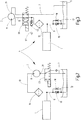
- the device has a pressure-actuated pump 3 which, in a fluid circuit 4, draws the aqueous urea solution from a tank 5 containing a fluid supply via a suction line 7 and returns it to the tank 5 via a return line 9.
- a fluid filter 15 connected upstream of the working unit 1 in order to ensure that the working unit 1 is supplied with fluid that is clean from contamination.
- the working unit 1 has, in the manner customary in SCR systems, an electronic control device which, depending on the respective operating state of an internal combustion engine (not shown), feeds the fluid under supply pressure in dosed injection quantities to an injection device which introduces the fluid into the exhaust gas flow.
- a pressure-limiting valve 17 set to the predetermined supply pressure of the working unit 1 has a spring-loaded check valve 19 in the line branch forming the return line 9, which forms a throttle point 18, which is indicated in symbols, which is referred to below Fig. 5 has been dealt with in more detail.
- a valve arrangement with a 3/2-way valve 23 is located in the suction line 7 in front of the suction side 21 of the pump 3.
- the pump 3 is a positive displacement pump, the displacement element being formed by a metal bellows 25 which has the shape of a bellows, which encloses a fluid space 29 within the pump housing 27.
- the pressure line 13 opens on the pressure side 11 via a pressure valve 31 into the fluid space 29, while a suction valve 33 is located on the suction side 21.
- the pump 3 can be operated with pressure medium by means of a drive unit 35, via which the working spaces in a drive cylinder 37 can be supplied with a pressure medium, such as pressure oil or air.
- a piston 39 located in the working cylinder 37 is connected to the metal bellows 35 via a piston rod 41, so that movements of the piston 39 change the volume of the fluid space 29.
- the use of a metal bellows 25 as a displacement element is particularly advantageous for fluids, such as aqueous urea solution, which are capable of creeping and are aggressive, because a clean separation of the fluid circuit 4 from the drive-side pressure medium, such as pressure oil, can be achieved over long periods of operation without sealing problems.
- aqueous urea solution which are capable of creeping and are aggressive
- the piston 39 is pretensioned by means of a compression spring 43 for a displacement movement which reduces the volume of the fluid space 29.
- the drive unit 35 has a switching valve in the form of a 3/2-way valve 45, via which the working chamber 47 in the drive cylinder 34 opposite the spring 43 can be alternately supplied with pressure medium, which is supplied from a pressure connection P, or can be connected to a return line or tank line 49 is, in which a secured by a check valve 51 return filter 53 is located. Between the pressure connection P and the tank line 49 there is a pressure control valve 55 which prescribes a desired drive pressure.
- pressure media such as compressed air or pressure oil are usually available in devices equipped with SCR systems.
- large diesels have their own hydraulic system for supplying lubricating oil.
- Fig. 1 and 2 an operating state is shown in which the directional control valve 23 is in a switch position, here referred to as the second switch position, which interrupts the pressure supply to the working unit 1.
- the pump 3 continues to run before it is switched off for the end of operation, it sucks in air from the environment 57 via the directional valve 23, while remaining urea solution is pushed out of the fluid chamber 29 and via the filter 15 and the throttle point 18 in the Check valve 19 of the pressure relief valve 17 is released to the tank 5, so that the pump 3 is ventilated after shutdown and contains little or no freezable fluid.
- the pump 3 When operation is resumed and the directional control valve 23 is switched to the other, first switching position, the pump 3 is automatically vented by sucking in the fluid via the suction line 7 and pushing out the air contained in the fluid space 29 via the line 13 and the throttle point 18 in the return line 9 In normal operation, the pump 3 thus works as a liquid pump.
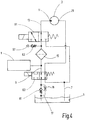
- the Fig. 3 shows a variant of the fluid circuit 4 in which the valve arrangement has a 4/2-way valve 59, this being in the first switching position corresponding to normal operation of the device.
- the directional control valve 59 connects the suction side 21 of the pump 3 to the environment 57 via a check valve 62, while the suction side 21 of the pump 3 is connected to the tank 5 via the line 7 which forms the suction line during supply operation.
- the pump 3 is therefore ventilated from the surroundings 57 via the check valve 62, while remaining fluid is expelled from the pump 3 via the line 7.
- the directional control valve 59 is switched to the first switching position, the pump 3 is again automatically vented via the suction line 7 and via the throttle point 18 of the check valve 19, which is part of the pressure relief valve 17 located in the return line 9.
- the valve arrangement has a second directional valve in the form of a 4/2-way valve 63, which is connected to the line branch forming the return line 9, which contains the check valve 19 having the throttle point 18, and is connected to the suction line 7.
- Both directional control valves 61, 63 of the valve arrangement are in the first switching position, which corresponds to normal supply operation.
- the check valve 62 leading to the environment 57 is connected to the inflow side of the filter 15, the outflow side of which is connected to the working unit 1.
- the directional control valve 61 connects the pressure side 11 of the pump 3 with the line 7, which is used as a suction line during normal operation with the suction side 21 of the pump 3.
- the pump 3 is running, it is ventilated from the environment 57 via the check valve 62 and the filter 15 to the suction side 21, while remaining fluid is expelled to the tank 5.
- the pump 3 is vented via the suction line 7, the air being expelled via the throttle point 18, so that the pump 3 again operates as a pure liquid pump.
- the Fig. 5 illustrates an advantageous design of the check valve 19 containing the throttle point 18.
- an inflow-side fluid connection 69 and an outflow-side fluid connection 71 which branches off from the fluid connection 69 at right angles, are located on the valve housing 57.
- a valve piston 73 is mounted in the valve housing 67 coaxially to the fluid connection 69 on the inflow side and is supported by a closing spring 75 biased into the closed position.
- the valve piston 73 has a through hole 77, from which a throttle hole 79, which forms the throttle point 18 and which leads to the downstream fluid connection 71, branches off at right angles.
- the check valve 19 can be set as a pressure relief valve to a prescribable pressure, while at the same time the throttle point 18 is formed with the desired throttling effect by dimensioning the throttle bore 79.
Landscapes
- Engineering & Computer Science (AREA)
- Mechanical Engineering (AREA)
- General Engineering & Computer Science (AREA)
- Exhaust Gas After Treatment (AREA)
- Details Of Reciprocating Pumps (AREA)
Claims (10)
- Dispositif de mise à disposition de fluides sous une pression pouvant être donnée à l'avance pour l'alimentation en pression d'un consommateur, comme une unité (1) de travail d'un système SCR (Selective Catalytic Réduction) pour traiter des gaz brûlés de moteurs à combustion interne, comprenant au moins une pompe (3), qui, dans un circuit (4) de fluide formé entre un réservoir (5) de fluide et le consommateur (1), prélève le fluide concerné du réservoir (5) de fluide et l'envoie au consommateur (1), dans lequel il est prévu dans le circuit (4) de fluide une branche (9) de conduit comportant un point (18) d'étranglement et un agencement (23, 59, 61, 63) de soupape, qui peut être mis dans une position de commutation mettant le réservoir (5) de fluide en communication avec la pompe (3), dans laquelle il est formé un trajet d'écoulement, qui comporte la branche (9) de conduit ayant le point (18) d'étranglement et qui peut être mis dans une deuxième position de commutation interrompant l'alimentation du consommateur, dans laquelle un trajet d'écoulement mettant la pompe (3) en communication avec l'atmosphère (57) ambiante est formée, caractérisé en ce que la pompe (3) est une pompe volumétrique, un organe d'impulsion étant formé par un soufflet (25) métallique, qui a la forme d'un soufflet à plis enfermant un espace (29) pour du fluide à l'intérieur du corps (27) de la pompe.
- Dispositif suivant la revendication 1, caractérisé en ce que la branche (9) de conduit comportant le point (18) d'étranglement est disposée entre le réservoir (5) de fluide et le côté (11) de refoulement de la pompe (3), dont le côté (21) d'aspiration communique dans la deuxième position de commutation de l'agencement de soupape par celui-ci avec l'atmosphère (57) extérieure.
- Dispositif suivant la revendication 1 ou 2, caractérisé en ce que le point (18) d'étranglement est formé par un trou (79) d'étranglement se trouvant dans l'obturateur (73) d'un clapet (19) anti-retour.
- Dispositif suivant la revendication 3, caractérisé en ce que le clapet (19) anti-retour formant le point (18) d'étranglement est une partie constitutive d'une soupape (17) de limitation de la pression en communication avec le côté (11) de refoulement de la pompe (3).
- Dispositif suivant l'une des revendications précédentes, caractérisé en ce que, dans la deuxième position de commutation de l'agencement (23, 59, 61, 63) de soupape, l'atmosphère (57) ambiante est par celui-ci en communication avec le côté (21) de refoulement de la pompe (3).
- Dispositif suivant l'une des revendications précédentes, caractérisé en ce que un filtre (15) de fluide est monté dans le circuit (4) de fluide en amont du consommateur (1).
- Dispositif suivant la revendication 6, caractérisé en ce que le côté d'afflux du filtre (15) communique par un clapet (62) anti-retour avec l'agencement (59, 61) de soupape et avec l'atmosphère (57) ambiante.
- Dispositif suivant l'une des revendications 6 ou 7 précédentes, caractérisé en ce que l'agencement de soupape a outre une première soupape (23, 59, 61) à plusieurs voies, raccordée à la pompe (3), une deuxième soupape (63) à plusieurs voies qui est montée entre le côté de sortie, raccordé au consommateur (1), du filtre (15) et le réservoir (5) de fluide et peut, dans la deuxième position de commutation de la première soupape (61) à plusieurs voies, être mis dans une position de commutation dans laquelle l'atmosphère (57) ambiante, par l'intermédiaire du filtre (15) et par l'intermédiaire de la deuxième soupape (63) à plusieurs voies, est en communication avec le côté (21) d'aspiration de la pompe (3).
- Dispositif suivant l'une des revendications 3 à 8, caractérisé en ce que l'agencement de soupape a des soupapes (23, 61) à 3/2 voies des soupapes (59, 63) à 4/2 voies respectivement sous la forme de soupapes à tiroir pouvant être actionnées électromagnétiquement.
- Dispositif suivant l'une des revendications 3 à 9 précédentes, caractérisé en ce que le clapet (19) anti-retour respectif, comportant le point (18) d'étranglement, a un corps (67) ayant des raccords (69, 71) pour du fluide s'étendant à angle droit l'un par rapport à l'autre, dans lequel il est prévu comme obturateur un piston (73) de soupape, chargé par un ressort, pouvant coulisser coaxialement vers l'un (69) des raccords (69, 71) pour du fluide et ayant un trou (77) coaxial de passage, dont bifurque à angle droit un trou (79) d'étranglement, qui mène à l'autre raccord (71) pour du fluide.
Applications Claiming Priority (2)
| Application Number | Priority Date | Filing Date | Title |
|---|---|---|---|
| DE102018001523.9A DE102018001523A1 (de) | 2018-02-27 | 2018-02-27 | Einrichtung zur Bereitstellung von unter einem vorgebbaren Druck stehenden Fluiden |
| PCT/EP2019/053239 WO2019166207A1 (fr) | 2018-02-27 | 2019-02-11 | Dispositif pour fournir des fluides sous une pression prédéterminée |
Publications (2)
| Publication Number | Publication Date |
|---|---|
| EP3710697A1 EP3710697A1 (fr) | 2020-09-23 |
| EP3710697B1 true EP3710697B1 (fr) | 2021-10-06 |
Family
ID=65409078
Family Applications (1)
| Application Number | Title | Priority Date | Filing Date |
|---|---|---|---|
| EP19704786.3A Active EP3710697B1 (fr) | 2018-02-27 | 2019-02-11 | Dispositif pour fournir des fluides sous une pression prédéterminée |
Country Status (3)
| Country | Link |
|---|---|
| EP (1) | EP3710697B1 (fr) |
| DE (1) | DE102018001523A1 (fr) |
| WO (1) | WO2019166207A1 (fr) |
Families Citing this family (4)
| Publication number | Priority date | Publication date | Assignee | Title |
|---|---|---|---|---|
| DE102021000327A1 (de) | 2021-01-22 | 2022-07-28 | Hydac Fluidtechnik Gmbh | Pumpenvorrichtung |
| DE102021002116A1 (de) | 2021-04-22 | 2022-10-27 | Hydac Fluidtechnik Gmbh | Pumpenvorrichtung |
| DE102021003639A1 (de) * | 2021-07-14 | 2023-01-19 | Hydac Technology Gmbh | Fördereinrichtung |
| US12247556B2 (en) | 2022-06-14 | 2025-03-11 | Hydac Fluidtechnik Gmbh | Pump device |
Family Cites Families (5)
| Publication number | Priority date | Publication date | Assignee | Title |
|---|---|---|---|---|
| DE102011088217A1 (de) * | 2011-12-12 | 2013-06-13 | Robert Bosch Gmbh | Dosieranordnung für ein flüssiges Abgasnachbehandlungsmittel und Dosierverfahren |
| DE102012205370A1 (de) * | 2012-04-02 | 2013-10-02 | Robert Bosch Gmbh | 3/2-Wegeventil |
| DE102012011975B4 (de) * | 2012-06-15 | 2018-09-20 | Rolf Prettl | Ventilanordnung und Tankmodul für ein Harnstoffeinspritzsystem |
| DE102012016631A1 (de) | 2012-08-22 | 2014-02-27 | Hydac Electronic Gmbh | Einrichtung zur Bereitstellung von unter einem vorgebbaren Druck stehenden Fluiden |
| DE102016216366A1 (de) * | 2016-08-31 | 2018-03-01 | Robert Bosch Gmbh | Dosiersystem für eine Abgasnachbehandlung einer Brennkraftmaschine |
-
2018
- 2018-02-27 DE DE102018001523.9A patent/DE102018001523A1/de not_active Withdrawn
-
2019
- 2019-02-11 EP EP19704786.3A patent/EP3710697B1/fr active Active
- 2019-02-11 WO PCT/EP2019/053239 patent/WO2019166207A1/fr not_active Ceased
Also Published As
| Publication number | Publication date |
|---|---|
| EP3710697A1 (fr) | 2020-09-23 |
| DE102018001523A1 (de) | 2019-08-29 |
| WO2019166207A1 (fr) | 2019-09-06 |
Similar Documents
| Publication | Publication Date | Title |
|---|---|---|
| EP3710697B1 (fr) | Dispositif pour fournir des fluides sous une pression prédéterminée | |
| DE102009038869B4 (de) | Vorrichtung zum dosierten Ausgeben eines Schmiermittels | |
| DE102010021399A1 (de) | Hydraulisch betätigte Nockenwellenverstellvorrichtung | |
| EP2128443B1 (fr) | Elément de pompe | |
| EP2817516B1 (fr) | Pompe pour un nettoyeur haute pression et un nettoyeur haute pression | |
| EP2005002B1 (fr) | Compresseur à vis comportant une soupape de délestage | |
| WO2020120064A1 (fr) | Pompe à broche hélicoïdale régulable | |
| DE10117418A1 (de) | Oszillierende Verdrängerpumpe | |
| EP1903238B1 (fr) | Système hydraulique | |
| DE102016210987A1 (de) | Druckbetätigter Verteiler für ein Fahrzeugwaschsystem | |
| DE102019000488B4 (de) | Vorrichtung zum Bereitstellen eines unter einem vorgebbaren Druck stehenden Fluids | |
| DE102012001369A1 (de) | Verstellbare Hydropumpe | |
| DE102010064114B4 (de) | Pumpe mit einer Drossel | |
| EP1970556A1 (fr) | Injecteur | |
| EP2694816B1 (fr) | Régulateur d'air pour compresseurs, en particulier pour compresseurs à vis | |
| DE102012018451A1 (de) | Wegeventil mit einer Mehrzahl kugelförmiger Dichtelemente | |
| EP1504173A1 (fr) | Dispositif d'alimentation en pression pour une commande electrohydraulique de soupapes d'echange gazeux dans des moteurs a combustion | |
| DE102007057446A1 (de) | Fluidfördereinrichtung und Ventileinrichtung sowie Verfahren zum Betreiben einer Fluidfördereinrichtung | |
| EP2049795A1 (fr) | Piston de pompe à piston pour systèmes de freinage de véhicules | |
| WO2014139529A1 (fr) | Ensemble à tiroir rotatif | |
| DE102014010119A1 (de) | Einrichtung zur Bereitstellung von unter einem vorgebbaren Druck stehenden Fluiden | |
| DE102007030224A1 (de) | Kraftstoffpumpe, insbesondere für ein Kraftstoffsystem einer Brennkraftmaschine | |
| EP3308019B1 (fr) | Pompe à piston alternatif à limitation de débit côté entrée | |
| DE102017222202A1 (de) | Kraftstofffördereinrichtung für kryogene Kraftstoffe | |
| DE202012100564U1 (de) | Pumpe für ein Hochdruckreinigungsgerät und Hochdruckreinigungsgerät |
Legal Events
| Date | Code | Title | Description |
|---|---|---|---|
| STAA | Information on the status of an ep patent application or granted ep patent |
Free format text: STATUS: UNKNOWN |
|
| STAA | Information on the status of an ep patent application or granted ep patent |
Free format text: STATUS: THE INTERNATIONAL PUBLICATION HAS BEEN MADE |
|
| PUAI | Public reference made under article 153(3) epc to a published international application that has entered the european phase |
Free format text: ORIGINAL CODE: 0009012 |
|
| STAA | Information on the status of an ep patent application or granted ep patent |
Free format text: STATUS: REQUEST FOR EXAMINATION WAS MADE |
|
| 17P | Request for examination filed |
Effective date: 20200617 |
|
| AK | Designated contracting states |
Kind code of ref document: A1 Designated state(s): AL AT BE BG CH CY CZ DE DK EE ES FI FR GB GR HR HU IE IS IT LI LT LU LV MC MK MT NL NO PL PT RO RS SE SI SK SM TR |
|
| AX | Request for extension of the european patent |
Extension state: BA ME |
|
| RIN1 | Information on inventor provided before grant (corrected) |
Inventor name: HEROLD, FRANK Inventor name: GROH, CHRISTIAN Inventor name: KORN, JEROME |
|
| GRAP | Despatch of communication of intention to grant a patent |
Free format text: ORIGINAL CODE: EPIDOSNIGR1 |
|
| STAA | Information on the status of an ep patent application or granted ep patent |
Free format text: STATUS: GRANT OF PATENT IS INTENDED |
|
| DAV | Request for validation of the european patent (deleted) | ||
| DAX | Request for extension of the european patent (deleted) | ||
| INTG | Intention to grant announced |
Effective date: 20210528 |
|
| GRAS | Grant fee paid |
Free format text: ORIGINAL CODE: EPIDOSNIGR3 |
|
| GRAA | (expected) grant |
Free format text: ORIGINAL CODE: 0009210 |
|
| STAA | Information on the status of an ep patent application or granted ep patent |
Free format text: STATUS: THE PATENT HAS BEEN GRANTED |
|
| AK | Designated contracting states |
Kind code of ref document: B1 Designated state(s): AL AT BE BG CH CY CZ DE DK EE ES FI FR GB GR HR HU IE IS IT LI LT LU LV MC MK MT NL NO PL PT RO RS SE SI SK SM TR |
|
| REG | Reference to a national code |
Ref country code: GB Ref legal event code: FG4D Free format text: NOT ENGLISH |
|
| REG | Reference to a national code |
Ref country code: CH Ref legal event code: EP Ref country code: AT Ref legal event code: REF Ref document number: 1436462 Country of ref document: AT Kind code of ref document: T Effective date: 20211015 |
|
| REG | Reference to a national code |
Ref country code: DE Ref legal event code: R096 Ref document number: 502019002454 Country of ref document: DE |
|
| REG | Reference to a national code |
Ref country code: IE Ref legal event code: FG4D Free format text: LANGUAGE OF EP DOCUMENT: GERMAN |
|
| REG | Reference to a national code |
Ref country code: LT Ref legal event code: MG9D |
|
| REG | Reference to a national code |
Ref country code: NL Ref legal event code: MP Effective date: 20211006 |
|
| PG25 | Lapsed in a contracting state [announced via postgrant information from national office to epo] |
Ref country code: RS Free format text: LAPSE BECAUSE OF FAILURE TO SUBMIT A TRANSLATION OF THE DESCRIPTION OR TO PAY THE FEE WITHIN THE PRESCRIBED TIME-LIMIT Effective date: 20211006 Ref country code: LT Free format text: LAPSE BECAUSE OF FAILURE TO SUBMIT A TRANSLATION OF THE DESCRIPTION OR TO PAY THE FEE WITHIN THE PRESCRIBED TIME-LIMIT Effective date: 20211006 Ref country code: FI Free format text: LAPSE BECAUSE OF FAILURE TO SUBMIT A TRANSLATION OF THE DESCRIPTION OR TO PAY THE FEE WITHIN THE PRESCRIBED TIME-LIMIT Effective date: 20211006 Ref country code: BG Free format text: LAPSE BECAUSE OF FAILURE TO SUBMIT A TRANSLATION OF THE DESCRIPTION OR TO PAY THE FEE WITHIN THE PRESCRIBED TIME-LIMIT Effective date: 20220106 |
|
| PG25 | Lapsed in a contracting state [announced via postgrant information from national office to epo] |
Ref country code: IS Free format text: LAPSE BECAUSE OF FAILURE TO SUBMIT A TRANSLATION OF THE DESCRIPTION OR TO PAY THE FEE WITHIN THE PRESCRIBED TIME-LIMIT Effective date: 20220206 Ref country code: SE Free format text: LAPSE BECAUSE OF FAILURE TO SUBMIT A TRANSLATION OF THE DESCRIPTION OR TO PAY THE FEE WITHIN THE PRESCRIBED TIME-LIMIT Effective date: 20211006 Ref country code: PT Free format text: LAPSE BECAUSE OF FAILURE TO SUBMIT A TRANSLATION OF THE DESCRIPTION OR TO PAY THE FEE WITHIN THE PRESCRIBED TIME-LIMIT Effective date: 20220207 Ref country code: PL Free format text: LAPSE BECAUSE OF FAILURE TO SUBMIT A TRANSLATION OF THE DESCRIPTION OR TO PAY THE FEE WITHIN THE PRESCRIBED TIME-LIMIT Effective date: 20211006 Ref country code: NO Free format text: LAPSE BECAUSE OF FAILURE TO SUBMIT A TRANSLATION OF THE DESCRIPTION OR TO PAY THE FEE WITHIN THE PRESCRIBED TIME-LIMIT Effective date: 20220106 Ref country code: NL Free format text: LAPSE BECAUSE OF FAILURE TO SUBMIT A TRANSLATION OF THE DESCRIPTION OR TO PAY THE FEE WITHIN THE PRESCRIBED TIME-LIMIT Effective date: 20211006 Ref country code: LV Free format text: LAPSE BECAUSE OF FAILURE TO SUBMIT A TRANSLATION OF THE DESCRIPTION OR TO PAY THE FEE WITHIN THE PRESCRIBED TIME-LIMIT Effective date: 20211006 Ref country code: HR Free format text: LAPSE BECAUSE OF FAILURE TO SUBMIT A TRANSLATION OF THE DESCRIPTION OR TO PAY THE FEE WITHIN THE PRESCRIBED TIME-LIMIT Effective date: 20211006 Ref country code: GR Free format text: LAPSE BECAUSE OF FAILURE TO SUBMIT A TRANSLATION OF THE DESCRIPTION OR TO PAY THE FEE WITHIN THE PRESCRIBED TIME-LIMIT Effective date: 20220107 Ref country code: ES Free format text: LAPSE BECAUSE OF FAILURE TO SUBMIT A TRANSLATION OF THE DESCRIPTION OR TO PAY THE FEE WITHIN THE PRESCRIBED TIME-LIMIT Effective date: 20211006 |
|
| REG | Reference to a national code |
Ref country code: DE Ref legal event code: R097 Ref document number: 502019002454 Country of ref document: DE |
|
| PG25 | Lapsed in a contracting state [announced via postgrant information from national office to epo] |
Ref country code: SM Free format text: LAPSE BECAUSE OF FAILURE TO SUBMIT A TRANSLATION OF THE DESCRIPTION OR TO PAY THE FEE WITHIN THE PRESCRIBED TIME-LIMIT Effective date: 20211006 Ref country code: SK Free format text: LAPSE BECAUSE OF FAILURE TO SUBMIT A TRANSLATION OF THE DESCRIPTION OR TO PAY THE FEE WITHIN THE PRESCRIBED TIME-LIMIT Effective date: 20211006 Ref country code: RO Free format text: LAPSE BECAUSE OF FAILURE TO SUBMIT A TRANSLATION OF THE DESCRIPTION OR TO PAY THE FEE WITHIN THE PRESCRIBED TIME-LIMIT Effective date: 20211006 Ref country code: EE Free format text: LAPSE BECAUSE OF FAILURE TO SUBMIT A TRANSLATION OF THE DESCRIPTION OR TO PAY THE FEE WITHIN THE PRESCRIBED TIME-LIMIT Effective date: 20211006 Ref country code: DK Free format text: LAPSE BECAUSE OF FAILURE TO SUBMIT A TRANSLATION OF THE DESCRIPTION OR TO PAY THE FEE WITHIN THE PRESCRIBED TIME-LIMIT Effective date: 20211006 Ref country code: CZ Free format text: LAPSE BECAUSE OF FAILURE TO SUBMIT A TRANSLATION OF THE DESCRIPTION OR TO PAY THE FEE WITHIN THE PRESCRIBED TIME-LIMIT Effective date: 20211006 |
|
| PLBE | No opposition filed within time limit |
Free format text: ORIGINAL CODE: 0009261 |
|
| STAA | Information on the status of an ep patent application or granted ep patent |
Free format text: STATUS: NO OPPOSITION FILED WITHIN TIME LIMIT |
|
| 26N | No opposition filed |
Effective date: 20220707 |
|
| PG25 | Lapsed in a contracting state [announced via postgrant information from national office to epo] |
Ref country code: MC Free format text: LAPSE BECAUSE OF FAILURE TO SUBMIT A TRANSLATION OF THE DESCRIPTION OR TO PAY THE FEE WITHIN THE PRESCRIBED TIME-LIMIT Effective date: 20211006 |
|
| REG | Reference to a national code |
Ref country code: CH Ref legal event code: PL |
|
| REG | Reference to a national code |
Ref country code: BE Ref legal event code: MM Effective date: 20220228 |
|
| PG25 | Lapsed in a contracting state [announced via postgrant information from national office to epo] |
Ref country code: LU Free format text: LAPSE BECAUSE OF NON-PAYMENT OF DUE FEES Effective date: 20220211 Ref country code: AL Free format text: LAPSE BECAUSE OF FAILURE TO SUBMIT A TRANSLATION OF THE DESCRIPTION OR TO PAY THE FEE WITHIN THE PRESCRIBED TIME-LIMIT Effective date: 20211006 |
|
| PG25 | Lapsed in a contracting state [announced via postgrant information from national office to epo] |
Ref country code: SI Free format text: LAPSE BECAUSE OF FAILURE TO SUBMIT A TRANSLATION OF THE DESCRIPTION OR TO PAY THE FEE WITHIN THE PRESCRIBED TIME-LIMIT Effective date: 20211006 |
|
| PG25 | Lapsed in a contracting state [announced via postgrant information from national office to epo] |
Ref country code: FR Free format text: LAPSE BECAUSE OF NON-PAYMENT OF DUE FEES Effective date: 20220228 |
|
| PG25 | Lapsed in a contracting state [announced via postgrant information from national office to epo] |
Ref country code: LI Free format text: LAPSE BECAUSE OF NON-PAYMENT OF DUE FEES Effective date: 20220228 Ref country code: IE Free format text: LAPSE BECAUSE OF NON-PAYMENT OF DUE FEES Effective date: 20220211 Ref country code: CH Free format text: LAPSE BECAUSE OF NON-PAYMENT OF DUE FEES Effective date: 20220228 |
|
| PG25 | Lapsed in a contracting state [announced via postgrant information from national office to epo] |
Ref country code: BE Free format text: LAPSE BECAUSE OF NON-PAYMENT OF DUE FEES Effective date: 20220228 |
|
| PG25 | Lapsed in a contracting state [announced via postgrant information from national office to epo] |
Ref country code: IT Free format text: LAPSE BECAUSE OF FAILURE TO SUBMIT A TRANSLATION OF THE DESCRIPTION OR TO PAY THE FEE WITHIN THE PRESCRIBED TIME-LIMIT Effective date: 20211006 |
|
| GBPC | Gb: european patent ceased through non-payment of renewal fee |
Effective date: 20230211 |
|
| PG25 | Lapsed in a contracting state [announced via postgrant information from national office to epo] |
Ref country code: GB Free format text: LAPSE BECAUSE OF NON-PAYMENT OF DUE FEES Effective date: 20230211 |
|
| PG25 | Lapsed in a contracting state [announced via postgrant information from national office to epo] |
Ref country code: GB Free format text: LAPSE BECAUSE OF NON-PAYMENT OF DUE FEES Effective date: 20230211 |
|
| PG25 | Lapsed in a contracting state [announced via postgrant information from national office to epo] |
Ref country code: MK Free format text: LAPSE BECAUSE OF FAILURE TO SUBMIT A TRANSLATION OF THE DESCRIPTION OR TO PAY THE FEE WITHIN THE PRESCRIBED TIME-LIMIT Effective date: 20211006 Ref country code: CY Free format text: LAPSE BECAUSE OF FAILURE TO SUBMIT A TRANSLATION OF THE DESCRIPTION OR TO PAY THE FEE WITHIN THE PRESCRIBED TIME-LIMIT Effective date: 20211006 |
|
| PG25 | Lapsed in a contracting state [announced via postgrant information from national office to epo] |
Ref country code: HU Free format text: LAPSE BECAUSE OF FAILURE TO SUBMIT A TRANSLATION OF THE DESCRIPTION OR TO PAY THE FEE WITHIN THE PRESCRIBED TIME-LIMIT; INVALID AB INITIO Effective date: 20190211 |
|
| PG25 | Lapsed in a contracting state [announced via postgrant information from national office to epo] |
Ref country code: TR Free format text: LAPSE BECAUSE OF FAILURE TO SUBMIT A TRANSLATION OF THE DESCRIPTION OR TO PAY THE FEE WITHIN THE PRESCRIBED TIME-LIMIT Effective date: 20211006 |
|
| PG25 | Lapsed in a contracting state [announced via postgrant information from national office to epo] |
Ref country code: MT Free format text: LAPSE BECAUSE OF FAILURE TO SUBMIT A TRANSLATION OF THE DESCRIPTION OR TO PAY THE FEE WITHIN THE PRESCRIBED TIME-LIMIT Effective date: 20211006 |
|
| PGFP | Annual fee paid to national office [announced via postgrant information from national office to epo] |
Ref country code: DE Payment date: 20250228 Year of fee payment: 7 |
|
| REG | Reference to a national code |
Ref country code: AT Ref legal event code: MM01 Ref document number: 1436462 Country of ref document: AT Kind code of ref document: T Effective date: 20240211 |
|
| PG25 | Lapsed in a contracting state [announced via postgrant information from national office to epo] |
Ref country code: AT Free format text: LAPSE BECAUSE OF NON-PAYMENT OF DUE FEES Effective date: 20240211 |
|
| PGFP | Annual fee paid to national office [announced via postgrant information from national office to epo] |
Ref country code: AT Payment date: 20260410 Year of fee payment: 5 |