EP3710727B1 - Réducteur de vitesse a train planétaire ou épicycloïdal de turbomachine - Google Patents
Réducteur de vitesse a train planétaire ou épicycloïdal de turbomachine Download PDFInfo
- Publication number
- EP3710727B1 EP3710727B1 EP18812236.0A EP18812236A EP3710727B1 EP 3710727 B1 EP3710727 B1 EP 3710727B1 EP 18812236 A EP18812236 A EP 18812236A EP 3710727 B1 EP3710727 B1 EP 3710727B1
- Authority
- EP
- European Patent Office
- Prior art keywords
- finger
- reducer
- axis
- oil
- axial
- Prior art date
- Legal status (The legal status is an assumption and is not a legal conclusion. Google has not performed a legal analysis and makes no representation as to the accuracy of the status listed.)
- Active
Links
Images



Classifications
-
- F—MECHANICAL ENGINEERING; LIGHTING; HEATING; WEAPONS; BLASTING
- F16—ENGINEERING ELEMENTS AND UNITS; GENERAL MEASURES FOR PRODUCING AND MAINTAINING EFFECTIVE FUNCTIONING OF MACHINES OR INSTALLATIONS; THERMAL INSULATION IN GENERAL
- F16H—GEARING
- F16H1/00—Toothed gearings for conveying rotary motion
- F16H1/28—Toothed gearings for conveying rotary motion with gears having orbital motion
- F16H1/2809—Toothed gearings for conveying rotary motion with gears having orbital motion with means for equalising the distribution of load on the planet gears
- F16H1/2827—Toothed gearings for conveying rotary motion with gears having orbital motion with means for equalising the distribution of load on the planet gears by allowing limited movement of the planet carrier, e.g. relative to its shaft
-
- F—MECHANICAL ENGINEERING; LIGHTING; HEATING; WEAPONS; BLASTING
- F02—COMBUSTION ENGINES; HOT-GAS OR COMBUSTION-PRODUCT ENGINE PLANTS
- F02C—GAS-TURBINE PLANTS; AIR INTAKES FOR JET-PROPULSION PLANTS; CONTROLLING FUEL SUPPLY IN AIR-BREATHING JET-PROPULSION PLANTS
- F02C7/00—Features, components parts, details or accessories, not provided for in, or of interest apart form groups F02C1/00 - F02C6/00; Air intakes for jet-propulsion plants
- F02C7/36—Power transmission arrangements between the different shafts of the gas turbine plant, or between the gas-turbine plant and the power user
-
- F—MECHANICAL ENGINEERING; LIGHTING; HEATING; WEAPONS; BLASTING
- F16—ENGINEERING ELEMENTS AND UNITS; GENERAL MEASURES FOR PRODUCING AND MAINTAINING EFFECTIVE FUNCTIONING OF MACHINES OR INSTALLATIONS; THERMAL INSULATION IN GENERAL
- F16H—GEARING
- F16H57/00—General details of gearing
- F16H57/04—Features relating to lubrication or cooling or heating
- F16H57/042—Guidance of lubricant
- F16H57/043—Guidance of lubricant within rotary parts, e.g. axial channels or radial openings in shafts
-
- F—MECHANICAL ENGINEERING; LIGHTING; HEATING; WEAPONS; BLASTING
- F16—ENGINEERING ELEMENTS AND UNITS; GENERAL MEASURES FOR PRODUCING AND MAINTAINING EFFECTIVE FUNCTIONING OF MACHINES OR INSTALLATIONS; THERMAL INSULATION IN GENERAL
- F16H—GEARING
- F16H57/00—General details of gearing
- F16H57/04—Features relating to lubrication or cooling or heating
- F16H57/0467—Elements of gearings to be lubricated, cooled or heated
- F16H57/0469—Bearings or seals
- F16H57/0471—Bearing
-
- F—MECHANICAL ENGINEERING; LIGHTING; HEATING; WEAPONS; BLASTING
- F16—ENGINEERING ELEMENTS AND UNITS; GENERAL MEASURES FOR PRODUCING AND MAINTAINING EFFECTIVE FUNCTIONING OF MACHINES OR INSTALLATIONS; THERMAL INSULATION IN GENERAL
- F16H—GEARING
- F16H57/00—General details of gearing
- F16H57/04—Features relating to lubrication or cooling or heating
- F16H57/0467—Elements of gearings to be lubricated, cooled or heated
- F16H57/0479—Gears or bearings on planet carriers
-
- F—MECHANICAL ENGINEERING; LIGHTING; HEATING; WEAPONS; BLASTING
- F16—ENGINEERING ELEMENTS AND UNITS; GENERAL MEASURES FOR PRODUCING AND MAINTAINING EFFECTIVE FUNCTIONING OF MACHINES OR INSTALLATIONS; THERMAL INSULATION IN GENERAL
- F16H—GEARING
- F16H57/00—General details of gearing
- F16H57/04—Features relating to lubrication or cooling or heating
- F16H57/048—Type of gearings to be lubricated, cooled or heated
- F16H57/0482—Gearings with gears having orbital motion
- F16H57/0486—Gearings with gears having orbital motion with fixed gear ratio
-
- F—MECHANICAL ENGINEERING; LIGHTING; HEATING; WEAPONS; BLASTING
- F16—ENGINEERING ELEMENTS AND UNITS; GENERAL MEASURES FOR PRODUCING AND MAINTAINING EFFECTIVE FUNCTIONING OF MACHINES OR INSTALLATIONS; THERMAL INSULATION IN GENERAL
- F16H—GEARING
- F16H57/00—General details of gearing
- F16H57/08—General details of gearing of gearings with members having orbital motion
- F16H57/082—Planet carriers
-
- F—MECHANICAL ENGINEERING; LIGHTING; HEATING; WEAPONS; BLASTING
- F05—INDEXING SCHEMES RELATING TO ENGINES OR PUMPS IN VARIOUS SUBCLASSES OF CLASSES F01-F04
- F05D—INDEXING SCHEME FOR ASPECTS RELATING TO NON-POSITIVE-DISPLACEMENT MACHINES OR ENGINES, GAS-TURBINES OR JET-PROPULSION PLANTS
- F05D2220/00—Application
- F05D2220/30—Application in turbines
- F05D2220/32—Application in turbines in gas turbines
- F05D2220/323—Application in turbines in gas turbines for aircraft propulsion, e.g. jet engines
-
- F—MECHANICAL ENGINEERING; LIGHTING; HEATING; WEAPONS; BLASTING
- F05—INDEXING SCHEMES RELATING TO ENGINES OR PUMPS IN VARIOUS SUBCLASSES OF CLASSES F01-F04
- F05D—INDEXING SCHEME FOR ASPECTS RELATING TO NON-POSITIVE-DISPLACEMENT MACHINES OR ENGINES, GAS-TURBINES OR JET-PROPULSION PLANTS
- F05D2260/00—Function
- F05D2260/40—Transmission of power
Definitions
- the present invention relates to the field of speed reducers with planetary or planetary gears for turbomachines, in particular aircraft.
- the state of the art includes in particular the documents WO-A1-2010/092263 , FR-A1-2 987 416 , EP-A1-1 464 869 , FR-A1-3 041 054 , FR-A-1 379 451 , WO-A1-94/29614 and WO-A2-2009/080030 .
- turbomachines in particular turbomachines comprising one or more propellers blowing a secondary flow, comprise a transmission system, called a reducer, to drive this or these propellers at the correct speed of rotation from the shaft of the power turbine of the primary body of the motor.
- reduction gears in particular on turbomachines with a fan propeller with a high bypass ratio, requires a particularly high oil flow to ensure the lubrication and cooling of their pinions and bearings.
- the oil flow depends on the architecture and is for example of the order of 6000 to 7000 liters per hour on takeoff for a particular architecture.
- Such a reducer comprises a planetary pinion or central pinion, called sun gear, an outer crown and satellite pinions, called satellites, which mesh with the sun gear and with the crown, the support of one of these three components having to be blocked rotating for the operation of the gear train.
- the sun gear and the crown are driving and driven, respectively, or vice versa.
- the reducer is then of the “planetary” type.
- the solar and the satellites can be housed in a cage which supports the guide bearings of the satellites as well as means for lubricating the satellites and the solar.
- the sun gear comprises internal splines for coupling to a first shaft of the turbomachine and the cage of the reducer is integral with a cylindrical shaft which comprises external splines for coupling to another shaft.
- connection of the cage to the barrel is generally rigid.
- the cage is connected to the barrel by flexible connections, as described in the document EP-A1-1 464 869 .
- the shaft comprises an annular row of axial arms which are connected by flexible links to the cage.
- the present invention proposes an improvement which provides a simple, effective and economical solution to this problem.
- the invention relates to a speed reducer with planetary or planetary gear train for a turbomachine, according to claim 1.
- the invention thus proposes bringing oil to the ball joints and in particular to the ball joint/finger interfaces, so as to lubricate their surfaces in contact and thus limit the appearance of fretting.
- the oil is here brought by means of lubrication integrated in the guide fingers of the ball joints.
- the present invention relates to a speed reducer with planetary or planetary gear train for a turbomachine, comprising a cage and a shaft comprising a row ring of axial arms engaged in the housings of the periphery of the cage, each arm having a recess for mounting a ball joint through which the finger of said housing passes.
- the figure 1 shows a turbomachine 1 which comprises, in a conventional manner, a fan propeller S, a low pressure compressor 1a, a high pressure compressor 1b, an annular combustion chamber 1c, a high pressure turbine 1d, a low pressure turbine 1e and a nozzle exhaust 1h.
- the high pressure compressor 1b and the high pressure turbine 1d are connected by a high pressure shaft 2 and form with it a high pressure body (HP).
- the low pressure compressor 1a and the low pressure turbine 1e are connected by a low pressure shaft 3 and form with it a low pressure body (LP).
- the fan propeller S is driven by a fan shaft 4 which is coupled to the LP shaft 3 by means of a planetary gear reduction gear 10 shown here schematically.
- the reducer 10 is positioned in the front part of the turbomachine.
- a fixed structure comprising schematically, here, an upstream part 5a and a downstream part 5b is arranged so as to form an enclosure E1 surrounding the reducer 10.
- This enclosure E1 is here closed upstream by joints at the level of a bearing allowing the crossing of the fan shaft 4, and downstream by seals at the level of the crossing of the LP shaft 3.
- the reducer 10 comprises a crown 14 which is fixed by means of a crown carrier (not shown) to the fixed structure 5a, 5b with flexible means arranged to enable it to follow any movements of the drive shaft. fan 4, in certain cases of degraded operation for example.
- the crown carrier is made up of a more or less flexible part which drives the crown and of a part maintained by bearings or bearings and on which the fan is mounted.
- Those fastening means are known to those skilled in the art and are not detailed here. A brief description can be found for example in FR-A1-2 987 416 .
- the reducer 10 engages on the one hand on the BP shaft 3 via splines 7 which drive a planetary or sun gear pinion 11, and on the other hand on the fan shaft 4 which is attached to a planet carrier 13.
- sun gear 11 whose axis of rotation X coincides with that of the turbomachine, drives a series of planet gears or planet gears 12, which are regularly distributed over the circumference of reducer 10.
- the number of satellites 12 is generally defined between three and six.
- the satellites 12 also rotate around the axis X of the turbomachine except in the case of a planetary where they rotate only around their axes of revolution, by meshing on internal teeth of the crown 14, which is fixed to a stator of the turbomachine by means of flanges 20 in the case of an epicyclic or fixed to a rotor of the turbomachine in the case of a planetary.
- Each of the satellites 12 rotates freely around a satellite axis 16 connected to the planet carrier 13, using a bearing which may be smooth, as shown in the figure 2 , or a bearing with rolling elements (ball or roller bearings).
- the figure 2 shows the routing of the oil to the reducer 10 and its path inside the latter. Arrows show on the figure 2 the path followed by the oil from, in this example, a buffer tank linked to the fixed structure of the turbomachine, down to the pinions and bearings to be lubricated.
- the lubricating device conventionally comprises three parts: a first part linked to the fixed structure and delivering the oil to the rotating parts of the reducer 10, a rotating wheel with the planet carrier 13 receiving this oil in the case of an epicyclic and a distributor assembled to the planet carrier, which are fixed on a planetary architecture, and oil distribution circuits supplied with oil by the impeller to route it to the places to be lubricated.
- the figures 3 to 5 illustrate a more concrete example of a reduction gear 110 here with an epicyclic gear train.
- the reference 130 designates the planet carrier of the reducer 110, which is here of the one-piece type comprising a part forming a cage 134 and a part forming a shaft 142.
- the cage comprises two annular walls 136, 138 coaxial and connected at their periphery by a cylindrical wall 140.
- the annular wall 136 is secured to the substantially cylindrical barrel 142, partially visible, comprising means for meshing with a fan disc of the turbomachine.
- the coupling means are for example longitudinal splines.
- the cylindrical wall 140 is perforated and comprises slots 143 passing through in the radial direction allowing the mounting of the satellites.
- the wall 138 comprises a central opening 144 (allowing the mounting of the solar panel) centered on the X axis and a series of orifices 146 regularly distributed around the X axis, the opening 144 and the orifices 146 being through in the axial direction ( figure 5 ).
- the holes 146 are used to mount the axes 148 of rotation of the satellites 150.
- the axes 148 are parallel to the axis X and are mounted in the cage 134 by axial translation passing through the holes 146. They are fixed at their longitudinal ends on the walls 136, 138, respectively.
- the satellites 150 are rotatably mounted on the axes 148 and have their outer peripheries which partly pass through the slots 143 with a view to their meshing with the outer crown of the reducer intended to surround the cage 134.
- the planet gears 150 mesh with the sun gear 151 which comprises rectilinear internal splines 151a for coupling to another shaft such as a turbine shaft.
- a wheel 120 is attached and fixed to the wall 138, on the side of its external face, that is to say the one which is not located on the side of the satellites 150.
- the function of the wheel 120 is to lubricate the reducer 110 and comprises lubricating means configured to supply lubricant to nozzles 172 and to shafts 148 and bearings 149.
- the oil supply to the nozzles makes it possible to lubricate the meshing teeth of the satellites 150 and the sun gear 151.
- the impeller 120 has a generally annular shape and comprises arms 120a projecting radially outwards, five in number in the example shown.
- the impeller 120 is intended to be mounted coaxially on the wall 138 and has a face 120b for bearing and fixing on this wall.
- the impeller 120 comprises a central opening 120c delimited on the outside by an annular part defining two annular grooves 158a, 158b which are coaxial and arranged axially one beside the other. These grooves 158a, 158b extend around the axis X and emerge radially towards the inside. Their radially outer bottom wall comprises orifices in fluid communication with radial channels 160, on the one hand, and radial ducts 162, on the other hand.
- oil is intended to be squirted into grooves 158a, 158b by lubricant supply means.
- lubricant supply means generally comprise a series of injectors which are arranged around the X axis and pass through the openings 120c, 144. The injectors are carried by a stator and spray lubricant radially outwards directly into the grooves 158a, 158b , which will then flow through channels 160 and conduits 162.
- Each of the ducts 162 communicates at its radially outer end with a cavity of a shaft 148 for the supply of lubricant to this shaft 148 and to the associated bearing 149.
- the lubricant supplied by the conduits 162 is intended to be injected into the cavities, then to flow through the aforementioned conduits to the periphery of the bearings 149.
- Each of the channels 160 communicates at its radially outer end with a longitudinal end of a nozzle 172 visible in particular at the figure 4 .
- the nozzles 172 have an elongated shape and extend parallel to the axis X. Their axes of elongation are denoted B. They are five in number and regularly distributed around the axis X, each being arranged between two axes 148 adjacent.
- Each nozzle 172 comprises orifices 176 for spraying oil on the teeth of the satellites 150.
- the nozzles 172 are fixed to the impeller 120 by means of screwed lugs 175, and the impeller 120 is attached and fixed by screws on the annular wall 138 of the planet carrier 130.
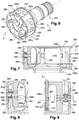
- the figures 6 to 8 represent another technology of planet carriers 230, in which the cage 234 and the shaft 242 are connected by ball joints.
- the cylindrical wall 240 of the cage 234 is here of the double skin type and comprises an outer skin 240a interrupted by the slots 243 and an inner skin 240b interrupted by the same slots 243.
- Each of the skins 240a, 240b is formed by an annular row of longitudinal strips of material which extends substantially parallel to the axis X.
- the strips of material of the skins are radially aligned and define between them inter-skin housings 280 which open axially on the walls 236, 238 of the cage.
- the housings 280 also emerge circumferentially, between the skins 240a, 240b.
- the cylindrical wall 240 of the cage thus comprises an annular row of housings 280. These housings 280 receive axial arms 282 secured to a substantially radial annular wall 282a of the shaft 242.
- the wall 282a is located at one axial end of the shaft 242, opposite its mating splines.
- the arms 282 extend axially from the wall 282a and are engaged by axial translation in the housings 280.
- Each arm 282 here has a flattened shape whose thickness is determined according to the inter-skin distance, that is to say the radial thickness of the housings 280.
- Each arm 282 further comprises a peripheral edge substantially in U, this peripheral edge having in cross-section an overall convex curved shape. This makes it possible to limit the sharp edges of the arms 282 and therefore the risk of deterioration by contact with the cage 234.
- Each arm 282 comprises, substantially in its middle, a recess 284 for mounting a ball joint 286 intended to be crossed by a finger 288 carried by the cage 234.
- the recess 284 has a substantially radial orientation relative to the axis X. It has a generally cylindrical shape and receives a ring 290 for guiding the ball joint 286.
- the cage 234 and the ball joint 286 have a thickness, measured in a radial with respect to the X axis, which is less than the inter-skin distance or the radial thickness of the housing 280, so as to be able to be engaged in this housing concomitantly with the arm 282 for supporting these parts.
- Each housing 280 is crossed by a finger 288 which has a substantially radial orientation with respect to the axis X.
- Each finger 288 comprises a cylindrical body 288a connected at one axial end, here radially internal, to an outer annular rim 288b.
- the finger 288 is here engaged by radial translation from the inside through radial orifices of the skins 240a, 240b, its rim 288b being intended to come into radial abutment on a cylindrical surface 291 of the internal skin 240b.
- the cylindrical body 288a comprises, at its axial end opposite the flange 288b, an annular groove for mounting a locking ring 292.
- This locking ring 292 is intended to bear radially on a cylindrical bearing surface of the outer skin 240a. After insertion of finger 288 into the holes in the skins, until rim 288b bears against bearing surface 291, ring 292 is mounted in the groove of body 288a to radially lock finger 288 vis-à-vis the skins 240a, 240b.
- the ball joint 286 surrounds a cylindrical surface 293 of the finger 288 which may be subject to fretting in operation.
- the invention proposes to integrate into the finger 288 means for lubricating the ball joint 286.
- the figure 9 represents a first embodiment of the invention in which the finger 288 comprises a central bore 294 for the circulation of oil connected to at least one channel 295 extending between the central bore and the cylindrical surface 293 of the finger intended to be surrounded by ball joint 286.
- the bore 294 extends along the axis of the finger 288, over a major part of the length thereof. It has an internal diameter noted D1.
- the bore comprises an axial end, located radially outside with respect to the axis X, which is closed, and an opposite axial end, located radially inside, which has in section a frustoconical shape flared radially towards the axis X.
- This tapered shape has a small base with a diameter D1 and a large base with a diameter D2 greater than D1.
- the number of channels 295 and their diameter, denoted D3, are predetermined. They are here two in number and extend radially with respect to the axis of the finger 288, in the same plane passing through this axis. They emerge at one end in the bore 294 and at the opposite end on the surface 293.
- the plane passing through the axis X and through the axis of the finger 288 also passes through the axis B of a nozzle 272. at least one orifice 296 for spraying oil towards finger 288 and in particular towards the flared end of its bore 294.
- the orifice 296 is here formed by the radially outer outlet of an oil passage channel 296a formed in the tubular wall of the nozzle 272.
- This channel 296 extends in a radial boss 297 of this tubular wall and has a length sufficient to orient and guide the oil to bore 294.
- the orifices 276 of the nozzle are oriented rather radially inward while its orifice(s) 296 are oriented rather radially outward.
- Ports 276, 296 are supplied by an internal oil circulation bore of nozzle 272.
- each finger 288 is associated with a nozzle 272 and lubricated by this nozzle 272.
- the number of fingers 288 is equal to the number of nozzles 272, which is equal to five in the example shown.
- the axes of the finger 288 and of the associated nozzle 272 are located in the same plane passing through the axis X.
- the figure 10 shows a variant embodiment of the invention in which the finger 288 comprises a cylindrical extension 298 radially inside.
- the bore 294 extends in this extension 298, which makes it possible to lengthen the latter and above all to reduce the radial distance between the projection orifice 296 and the flared end of the bore 294.
- extension 298 has an outer diameter less than the diameter of said cylindrical surface 293 and extends radially inward from rim 288b of finger 288.
- oil is projected through the orifice 296 in the direction of the bore 294 (arrow 299).
- the nozzle 272 and the finger 288 are integral in rotation with the planet carrier and therefore rotate at the same speed.
- the oil projected by the nozzle is centrifuged and is received in the bore. It will then flow radially from the inside out to the channels 295 (arrows 300), to then be transported to the surface 293, still under the effect of centrifugal forces.
- the channels 295 can be oriented so that their outlets on the surface 293 are located upstream and/or downstream of the preferred zone Z for application of the fretting type load, and/or at the level of this zone Z (cf. figure 12 ).
- the channels 295 can also be oriented in directions facilitating the flow of oil to the surface 293, such as for example radially outward with respect to the axis X, as shown in figure 13 .
- the solution proposed by the invention thus consists in bringing oil to the finger/ball joint interfaces to lubricate the surfaces 293 and thus limit the appearance of fretting. Very little oil may be necessary to eliminate the fretting on this interface, but in the present case it is necessary to bring oil to a rotating part, and to a part not intended to be supplied with oil.
- the nozzles 272 are used in the example shown, which are relatively close. These nozzles bring pressurized oil to the gearbox gears to cool and lubricate the teeth in operation.
- the solution therefore consists in making at least one additional orifice 296 in the nozzle to have a jet of oil which goes in the direction of the guide finger 288 of the ball joint 286.
- the oil jet Since we are in a centrifugal field (rotating parts), the oil jet will have a trajectory which will initially follow the centrifugal field. The oil is then guided to the interface to be lubricated via the bore 294 and the channels 295. The finger being subjected to the centrifugal field, any drop of oil which enters the bore 294 will be forced to flow to the interface by the centrifugal field and thus ensure the interface lubrication.
- the flared shape at the inlet of the bore makes it possible to capture a maximum of oil and therefore to maximize the oil supply to the finger 288. Depending on the architecture, it is possible that the nozzle 272 is too far to supply correctly the finger 288.
- the change of mark and the relative wind can burst the jet of oil at a certain distance from the nozzle. If this distance is less than the distance between the finger and the nozzle, the oil will not reach the finger.
- the variant of the figure 11 makes it possible to extend the finger 288 to collect the oil before the burst of the jet.
Landscapes
- Engineering & Computer Science (AREA)
- General Engineering & Computer Science (AREA)
- Mechanical Engineering (AREA)
- Chemical & Material Sciences (AREA)
- Combustion & Propulsion (AREA)
- General Details Of Gearings (AREA)
- Retarders (AREA)
Description
- La présente invention concerne le domaine des réducteurs de vitesse à train planétaire ou à train épicycloïdal pour turbomachine en particulier d'aéronef.
- L'état de l'art comprend notamment les documents
WO-A1-2010/092263 ,FR-A1-2 987 416 EP-A1-1 464 869 ,FR-A1-3 041 054 FR-A-1 379 451 WO-A1-94/29614 WO-A2-2009/080030 . - Les turbomachines actuelles, notamment les turbomachines comportant une ou plusieurs hélices soufflant un flux secondaire, comprennent un système de transmission, appelé réducteur, pour entraîner cette ou ces hélices à la bonne vitesse de rotation à partir de l'arbre de la turbine de puissance du corps primaire du moteur.
- Le fonctionnement des réducteurs, en particulier sur des turbomachines avec hélice de soufflante à fort taux de dilution, nécessite un débit d'huile particulièrement important pour assurer la lubrification et le refroidissement de leurs pignons et paliers. Le débit d'huile est fonction de l'architecture et est par exemple de l'ordre de 6000 à 7000 litres par heure au décollage pour une architecture particulière.
- Parmi les réducteurs utilisés, on trouve les trains planétaires et épicycloïdaux qui ont l'avantage d'offrir des taux de réduction importants de la vitesse de rotation dans des encombrements réduits.
- Un tel réducteur comprend un pignon planétaire ou pignon central, appelé solaire, une couronne extérieure et des pignons satellites, appelés satellites, qui sont en prise avec le solaire et avec la couronne, le support de l'un de ces trois composants devant être bloqué en rotation pour le fonctionnement du train d'engrenages.
- Lorsque le porte-satellites est fixe en rotation, le solaire et la couronne sont menant et mené, respectivement, ou inversement. Le réducteur est alors du type « planétaire ».
- Dans le cas inverse d'un réducteur à train épicycloïdal, la couronne extérieure est fixe en rotation et le solaire et le porte-satellites sont menants et menés.
- Le solaire et les satellites peuvent être logés dans une cage qui supportent les paliers de guidage des satellites ainsi que des moyens de lubrification des satellites et du solaire. Le solaire comprend des cannelures internes d'accouplement à un premier arbre de la turbomachine et la cage du réducteur est solidaire d'un fût cylindrique qui comprend des cannelures externes d'accouplement à un autre arbre.
- La liaison de la cage au fût est en général rigide. En variante, on peut envisager une technologie dans laquelle la cage est reliée au fût par des liaisons souples, telles que décrites dans le document
EP-A1-1 464 869 . Dans un tel cas, le fût comprend une rangée annulaire de bras axiaux qui sont reliés par des liaisons souples à la cage. - On a proposé de réaliser ces liaisons souples par des rotules, les bras portant des rotules traversées par des doigts s'étendant dans des logements axiaux prévus à la périphérie de la cage.
- En fonctionnement, lors de la mise sous couple du porte-satellites, les bras vont fléchir et transmettre le couple à la cage. Les rotules permettent de ne pas transmettre le fléchissement des bras aux doigts. Cependant, pour des questions de montage, des jeux sont présents entre les doigts et les rotules. Ainsi, lors des déformations, des déplacements relatifs entre les doigts et les rotules apparaissent. Ces déplacements relatifs sur des interfaces métal / métal génèrent des usures par frottement (du type fretting), ce qui peut mener à la rupture des liaisons.
- La présente invention propose un perfectionnement qui apporte une solution simple, efficace et économique à ce problème.
- L'invention concerne un réducteur de vitesse à train planétaire ou épicycloïdal de turbomachine, selon la revendication 1.
- L'invention propose ainsi d'amener de l'huile jusqu'aux rotules et en particulier aux interfaces rotule / doigt, de façon à lubrifier leurs surfaces en contact et ainsi limiter l'apparition de fretting. L'huile est ici amenée par des moyens de lubrification intégrés dans les doigts de guidage des rotules.
- Le réducteur selon l'invention peut comprendre une ou plusieurs des caractéristiques suivantes, prises isolément les unes des autres, ou en combinaison les unes avec les autres :
- chaque doigt comprend un alésage central de circulation d'huile relié à au moins un canal s'étendant entre ledit alésage central et une surface cylindrique externe du doigt destinée à être entourée par ladite rotule ; les moyens de lubrification sont ainsi formés simplement par des alésages et canaux prévus dans les doigts de guidage des rotules ;
- ledit alésage central débouche à une extrémité axiale radialement interne dudit doigt, et a en section à cette extrémité une forme tronconique évasée radialement vers l'intérieur ; de l'huile peut être projetée directement dans cette extrémité évasée, et s'écouler, du fait des forces centrifuges, dans l'alésage et le canal jusqu'à la rotule ;
- ledit alésage central s'étend le long d'un prolongement axial cylindrique dudit doigt, qui s'étend radialement vers l'intérieur ; ce prolongement peut être conçu pour diminuer la distance radiale entre l'alésage d'une part, et la source d'huile d'autre part ; cette source d'huile est par exemple formée par des moyens de projection, tels qu'un gicleur ;
- ledit prolongement axial a un diamètre externe inférieur au diamètre de ladite surface cylindrique, et/ou s'étend radialement vers l'intérieur depuis un rebord annulaire externe du doigt ;
- ledit au moins un canal a une orientation sensiblement radiale par rapport à l'axe longitudinal dudit doigt, ou est incliné par rapport à cet axe, par exemple radialement vers l'extérieur par rapport à l'axe X du solaire ; l'inclinaison du ou de chaque canal est déterminée en fonction des zones à lubrifier du doigt ainsi que des forces centrifuges appliquées à l'huile en fonctionnement.
- La présente invention concerne un réducteur de vitesse à train planétaire ou épicycloïdal de turbomachine, comportant une cage et un fût comportant une rangée annulaire de bras axiaux engagés dans les logements de la périphérie de la cage, chaque bras comportant un évidement de montage d'une rotule traversée par le doigt dudit logement.
- Le réducteur selon l'invention peut comprendre une ou plusieurs des caractéristiques suivantes, prises isolément les unes des autres, ou en combinaison les unes avec les autres :
- le réducteur comprend des moyens de lubrification des satellites qui comportent une rangée annulaire de gicleurs d'huile s'étendant parallèlement à l'axe X et répartis autour de cet axe X, les gicleurs étant configurés pour projeter de l'huile vers lesdits doigts ; l'invention propose ainsi d'utiliser les gicleurs de lubrification des satellites, pour lubrifier les interfaces entre les doigts et les rotules ;
- le nombre de gicleurs est égal au nombre de doigts et chaque gicleur s'étend dans un plan passant par l'axe X, qui passe également par un doigt ; ceci permet de simplifier l'alimentation en huile des alésages des doigts par les gicleurs ;
- chaque gicleur comprend un alésage interne de circulation d'huile relié à au moins un canal de passage d'huile s'étendant depuis ledit alésage jusqu'à au moins un orifice de projection d'huile situé à la périphérie dudit gicleur et orienté vers un desdits doigts ; de l'huile est ainsi projetée par le gicleur dans l'alésage du doigt, cette huile s'écoulera ensuite jusqu'à la rotule du fait des forces centrifuges ;
- ledit au moins un orifice est situé au sommet d'un bossage radial dudit gicleur ; le bossage permet de rallonger la longueur dudit au moins un canal et d'améliorer le guidage de l'huile avant sa projection.
- D'autres caractéristiques et avantages ressortiront de la description qui suit d'un mode de réalisation non limitatif de l'invention en référence aux dessins annexés sur lesquels :
- la
figure 1 est une vue schématique en coupe axiale d'une turbomachine utilisant l'invention, - la
figure 2 est une vue schématique en coupe axiale d'un réducteur à train épicycloïdal, - la
figure 3 est une vue schématique en perspective d'un réducteur à train épicycloïdal, - la
figure 4 est une vue schématique en perspective d'un rouet et de gicleurs du réducteur de lafigure 3 , - la
figure 5 est une vue schématique en perspective d'un porte-satellites du réducteur de lafigure 3 , - la
figure 6 est une vue schématique en perspective d'un porte-satellites d'un réducteur selon l'invention, - la
figure 7 est une vue schématique partielle, en coupe axiale, et à plus grande échelle, d'une partie du porte-satellites de lafigure 6 , - la
figure 8 est une vue à plus grande échelle d'une partie de lafigure 7 , sans le perfectionnement proposé par l'invention, - la
figure 9 est une vue à plus grande échelle d'une partie de lafigure 7 , avec le perfectionnement proposé par l'invention, - la
figure 10 est une vue similaire à celle de lafigure 9 et illustrant une variante de réalisation de l'invention, - la
figure 11 est une vue à plus grande échelle d'une partie de lafigure 10 , - la
figure 12 est une vue très schématique en coupe transversale d'un doigt de guidage de rotule, et - la
figure 13 est une vue similaire à celle de lafigure 11 et illustrant une autre variante de réalisation de l'invention. - La
figure 1 montre une turbomachine 1 qui comporte, de manière classique, une hélice de soufflante S, un compresseur basse pression 1a, un compresseur haute pression 1b, une chambre annulaire de combustion 1c, une turbine haute pression 1d, une turbine basse pression 1e et une tuyère d'échappement 1h. Le compresseur haute pression 1b et la turbine haute pression 1d sont reliés par un arbre haute pression 2 et forment avec lui un corps haute pression (HP). Le compresseur basse pression 1a et la turbine basse pression 1e sont reliés par un arbre basse pression 3 et forment avec lui un corps basse pression (BP). - L'hélice de soufflante S est entraînée par un arbre de soufflante 4 qui est couplé à l'arbre BP 3 au moyen d'un réducteur 10 à train épicycloïdal représenté ici schématiquement.
- Le réducteur 10 est positionné dans la partie avant de la turbomachine. Une structure fixe comportant schématiquement, ici, une partie amont 5a et une partie aval 5b est agencée de manière à former un enceinte E1 entourant le réducteur 10. Cette enceinte E1 est ici fermée en amont par des joints au niveau d'un palier permettant la traversée de l'arbre de soufflante 4, et en aval par des joints au niveau de la traversée de l'arbre BP 3.
- En référence à la
figure 2 , le réducteur 10 comprend une couronne 14 qui est fixée par l'intermédiaire d'un porte-couronne (non représenté) à la structure fixe 5a, 5b avec des moyens souples agencés pour lui permettre de suivre les mouvements éventuels de l'arbre de soufflante 4, dans certains cas de fonctionnement dégradés par exemple. Dans une architecture planétaire, le porte-couronne est composé d'une partie plus ou moins souple qui entraine la couronne et d'une partie maintenue par des roulements ou des paliers et sur lequel vient se monter la soufflante. Ces moyens de fixation sont connus de l'homme du métier et ne sont pas détaillés ici. Une brève description peut en être trouvée par exemple dansFR-A1-2 987 416 - Le réducteur 10 embraye d'une part sur l'arbre BP 3 par l'intermédiaire de cannelures 7 qui entraînent un pignon d'engrenage planétaire ou solaire 11, et d'autre part sur l'arbre de soufflante 4 qui est attaché à un porte-satellites 13. Classiquement, le solaire 11, dont l'axe de rotation X est confondu avec celui de la turbomachine, entraîne une série de pignons de satellites ou satellites 12, qui sont répartis régulièrement sur la circonférence du réducteur 10. Le nombre de satellites 12 est généralement défini entre trois et six. Les satellites 12 tournent aussi autour de l'axe X de la turbomachine sauf dans le cas d'un planétaire où ils tournent uniquement autour de leurs axes de révolution, en engrenant sur des dentures internes de la couronne 14, qui est fixée à un stator de la turbomachine par l'intermédiaire de brides 20 dans le cas d'un épicycloïdal ou fixé à un rotor de la turbomachine dans le cas d'un planétaire. Chacun des satellites 12 tourne librement autour d'un axe de satellite 16 relié au porte-satellite 13, à l'aide d'un palier qui peut être lisse, comme représenté sur la
figure 2 , ou un palier à éléments roulants (roulements à billes ou à rouleaux). - La rotation des satellites 12 autour de leur axe de satellite 16, du fait de la coopération de leurs pignons avec les dentures de la couronne 14, entraîne la rotation du porte-satellites 13 autour de l'axe X, et par conséquent celle de l'arbre de soufflante 4 qui lui est lié, à une vitesse de rotation qui est inférieure à celle de l'arbre BP 3.
- La
figure 2 montre l'acheminement de l'huile vers le réducteur 10 et son cheminement à l'intérieur de celui-ci. Des flèches montrent sur lafigure 2 le cheminement suivi par l'huile depuis, sur cet exemple, un réservoir tampon lié à la structure fixe de la turbomachine, jusqu'aux pignons et aux paliers à lubrifier. Le dispositif de lubrification comporte classiquement trois parties : une première partie liée à la structure fixe et délivrant l'huile vers les parties tournantes du réducteur 10, un rouet tournant avec le porte-satellites 13 réceptionnant cette huile dans le cas d'un épicycloïdal et d'un distributeur assemblé au porte-satellite, qui sont fixes sur une architecture planétaire, et des circuits de distribution d'huile alimentés en huile par le rouet pour l'acheminer vers les endroits à lubrifier. - Les
figures 3 à 5 illustrent un exemple plus concret d'un réducteur 110 ici à train épicycloïdal. - La référence 130 désigne le porte-satellites du réducteur 110, qui est ici du type monobloc comprenant une partie formant une cage 134 et une partie formant un fût 142. La cage comporte deux parois annulaires 136, 138 coaxiales et reliées à leur périphérie par une paroi cylindrique 140.
- La paroi annulaire 136 est solidaire du fût 142 sensiblement cylindrique, partiellement visible, comportant des moyens d'engrènement avec un disque de soufflante de la turbomachine. Les moyens d'accouplement sont par exemple des cannelures longitudinales.
- Dans l'exemple représenté, la paroi cylindrique 140 est ajourée et comprend des lumières 143 traversantes en direction radiale permettant le montage des satellites.
- La paroi 138 comprend une ouverture centrale 144 (permettant le montage du solaire) centrée sur l'axe X et une série d'orifices 146 régulièrement répartis autour de l'axe X, l'ouverture 144 et les orifices 146 étant traversants en direction axiale (
figure 5 ). - Les orifices 146 servent au montage des axes 148 de rotation des satellites 150. Les axes 148 sont parallèles à l'axe X et sont montés dans la cage 134 par translation axiale en passant par les orifices 146. Ils sont fixés à leurs extrémités longitudinales sur les parois 136, 138, respectivement.
- Les satellites 150 sont montés à rotation sur les axes 148 et ont leurs périphéries externes qui traversent en partie les lumières 143 en vue de leur engrènement avec la couronne externe du réducteur destinée à entourer la cage 134.
- Les satellites 150 engrènent avec le solaire 151 qui comprend des cannelures rectilignes internes 151a d'accouplement à un autre arbre tel qu'un arbre de turbine.
- Un rouet 120 est rapporté et fixé sur la paroi 138, du côté de sa face externe, c'est-à-dire celle qui n'est pas située du côté des satellites 150. Le rouet 120 a pour fonction de lubrifier le réducteur 110 et comprend des moyens de lubrification configurés pour amener du lubrifiant jusqu'à des gicleurs 172 et jusqu'aux axes 148 et paliers 149. L'alimentation en huile des gicleurs permet de lubrifier les dents d'engrènement des satellites 150 et du solaire 151.
- Le rouet 120 a une forme générale annulaire et comprend des bras 120a en saillie radiale vers l'extérieur, au nombre de cinq dans l'exemple représenté. Le rouet 120 est destiné à être monté coaxialement sur la paroi 138 et comporte une face 120b d'appui et de fixation sur cette paroi.
- Le rouet 120 comporte une ouverture centrale 120c délimitée extérieurement par une partie annulaire définissant deux gorges annulaires 158a, 158b coaxiales et disposées axialement l'une à côté de l'autre. Ces gorges 158a, 158b s'étendent autour de l'axe X et débouchent radialement vers l'intérieur. Leur paroi de fond radialement externe comprend des orifices en communication fluidique avec des canaux radiaux 160, d'une part, et des conduits radiaux 162, d'autre part.
- Bien que cela ne soit pas représenté, de l'huile est destinée à être projetée dans les gorges 158a, 158b par des moyens d'alimentation en lubrifiant. Ces moyens comprennent en général une série d'injecteurs qui sont disposés autour de l'axe X et traversent les ouvertures 120c, 144. Les injecteurs sont portés par un stator et pulvérisent du lubrifiant radialement vers l'extérieur directement dans les gorges 158a, 158b, qui va ensuite s'écouler dans les canaux 160 et conduits 162.
- Chacun des conduits 162 communique à son extrémité radialement externe avec une cavité d'un axe 148 en vue de l'alimentation en lubrifiant de cet axe 148 et du palier 149 associé. Le lubrifiant amené par les conduits 162 est destiné à être injecté dans les cavités, puis à s'écouler à travers les conduits précités jusqu'à la périphérie des paliers 149.
- Chacun des canaux 160 communique à son extrémité radialement externe avec une extrémité longitudinale d'un gicleur 172 visible notamment à la
figure 4 . Les gicleurs 172 ont une forme allongée et s'étendent parallèlement à l'axe X. Leurs axes d'allongement sont notés B. Ils sont au nombre de cinq et régulièrement répartis autour de l'axe X en étant chacun disposés entre deux axes 148 adjacents. - Chaque gicleur 172 comprend des orifices 176 de projection d'huile sur les dentures des satellites 150.
- Les gicleurs 172 sont fixés au rouet 120 au moyen de pattes 175 vissées, et le rouet 120 est rapporté et fixé par des vis sur la paroi annulaire 138 du porte-satellites 130.
- Dans les
figures 6 et suivantes, les éléments déjà décrits dans ce qui précède sont désignés par les mêmes références augmentées d'une centaine. - Les
figures 6 à 8 représentent une autre technologie de porte-satellites 230, dans laquelle la cage 234 et le fût 242 sont reliés par des liaisons à rotules. - La paroi cylindrique 240 de la cage 234 est ici du type à double peau et comprend une peau externe 240a interrompue par les lumières 243 et une peau interne 240b interrompue par les mêmes lumières 243.
- Chacune des peaux 240a, 240b est formée par une rangée annulaire de bandes longitudinales de matière qui s'étend sensiblement parallèlement à l'axe X. Les bandes de matière des peaux sont alignées radialement et définissent entre elles des logements 280 inter-peaux qui débouchent axialement sur les parois 236, 238 de la cage. Les logements 280 débouchent également circonférentiellement, entre les peaux 240a, 240b.
- La paroi cylindrique 240 de la cage comprend ainsi une rangée annulaire de logements 280. Ces logements 280 reçoivent des bras axiaux 282 solidaires d'une paroi annulaire 282a sensiblement radiale du fût 242. La paroi 282a est située à une extrémité axiale du fût 242, opposée à ses cannelures d'accouplement. Les bras 282 s'étendent axialement depuis la paroi 282a et sont engagés par translation axiale dans les logements 280.
- Chaque bras 282 présente ici une forme aplatie dont l'épaisseur est déterminée en fonction de la distance inter-peaux, c'est-à-dire de l'épaisseur radiale des logements 280. Chaque bras 282 comprend en outre un bord périphérique sensiblement en U, ce bord périphérique ayant en section transversale une forme générale incurvée convexe. Ceci permet de limiter les arêtes vives des bras 282 et donc le risque de détérioration par contact avec la cage 234.
- Chaque bras 282 comprend, sensiblement en son milieu, un évidement 284 de montage d'un rotule 286 destinée à être traversé par un doigt 288 porté par la cage 234.
- L'évidement 284 a une orientation sensiblement radiale par rapport à l'axe X. Il a une forme générale cylindrique et reçoit une bague 290 de guidage de la rotule 286. La cage 234 et la rotule 286 ont une épaisseur, mesurée dans une direction radiale par rapport à l'axe X, qui est inférieure à la distance inter-peaux ou l'épaisseur radiale du logement 280, de façon à pouvoir être engagées dans ce logement concomitamment avec le bras 282 de support de ces pièces.
- Chaque logement 280 est traversé par un doigt 288 qui a une orientation sensiblement radiale par rapport à l'axe X. Chaque doigt 288 comporte un corps cylindrique 288a reliée à une extrémité axiale, ici radialement interne, à un rebord annulaire externe 288b. Le doigt 288 est ici engagé par translation radiale depuis l'intérieur à travers des orifices radiaux des peaux 240a, 240b, son rebord 288b étant destiné à venir en appui radial sur une portée cylindrique 291 de la peau interne 240b. Le corps cylindrique 288a comprend, à son extrémité axiale opposée au rebord 288b, une rainure annulaire de montage d'un anneau de verrouillage 292. Cet anneau de verrouillage 292 est destiné à prendre appui radialement sur une portée cylindrique de la peau externe 240a. Après insertion du doigt 288 dans les orifices des peaux, jusqu'à mise en appui du rebord 288b sur la portée 291, l'anneau 292 est monté dans la rainure du corps 288a pour verrouiller radialement le doigt 288 vis-à-vis des peaux 240a, 240b.
- Comme on le voit à la
figure 8 , la rotule 286 entoure une surface cylindrique 293 du doigt 288 qui peut faire l'objet de fretting en fonctionnement. Pour limiter ou supprimer ce phénomène, l'invention propose d'intégrer au doigt 288 des moyens de lubrification de la rotule 286. - La
figure 9 représente un premier mode de réalisation de l'invention dans lequel le doigt 288 comprend un alésage central 294 de circulation d'huile relié à au moins un canal 295 s'étendant entre l'alésage central et la surface cylindrique 293 du doigt destinée à être entourée par la rotule 286. - L'alésage 294 s'étend le long de l'axe du doigt 288, sur une majeure partie de la longueur de celui-ci. Il a un diamètre interne noté D1. L'alésage comprend une extrémité axiale, située radialement à l'extérieur par rapport à l'axe X, qui est fermée, et une extrémité axiale opposée, située radialement à l'intérieur, qui a en section une forme tronconique évasée radialement vers l'axe X. Cette forme tronconique présente une petite base de diamètre D1 et une grande base de diamètre D2 supérieure à D1.
- Le nombre de canaux 295 et leur diamètre, noté D3, sont prédéterminés. Ils sont ici au nombre de deux et s'étendent radialement par rapport à l'axe du doigt 288, dans un même plan passant par cet axe. Ils débouchent à une extrémité dans l'alésage 294 et à l'extrémité opposée sur la surface 293.
- Comme cela est visible à la
figure 9 , le plan passant par l'axe X et par l'axe du doigt 288 passe également par l'axe B d'un gicleur 272. En plus des orifices 276 de projection d'huile vers les dentures des satellites, le gicleur 272 comprend au moins un orifice 296 de projection d'huile vers le doigt 288 et en particulier vers l'extrémité évasée de son alésage 294. - L'orifice 296 est ici formé par le débouché radialement externe d'un canal 296a de passage d'huile formé dans la paroi tubulaire du gicleur 272. Ce canal 296 s'étend dans un bossage radial 297 de cette paroi tubulaire et a une longueur suffisante pour orienter et guider l'huile vers l'alésage 294. Comme on le voit à la
figure 9 , les orifices 276 du gicleur sont orientés plutôt radialement vers l'intérieur alors que son ou ses orifices 296sont orientés plutôt radialement vers l'extérieur. Les orifices 276, 296 sont alimentés par un alésage interne de circulation d'huile du gicleur 272. - On comprend donc que chaque doigt 288 est associé à un gicleur 272 et lubrifié par ce gicleur 272. Autrement dit, le nombre de doigts 288 est égal au nombre de gicleurs 272, qui est égal à cinq dans l'exemple représenté. De plus, comme évoqué dans ce qui précède, les axes du doigt 288 et du gicleur 272 associé sont situés dans un même plan passant par l'axe X.
- La
figure 10 représente une variante de réalisation de l'invention dans laquelle le doigt 288 comprend un prolongement cylindrique 298 radialement interne. L'alésage 294 s'étend dans ce prolongement 298, ce qui permet de rallonger ce dernier et surtout de réduire la distance radiale entre l'orifice de projection 296 et l'extrémité évasée de l'alésage 294. - La
figure 10 montre que le prolongement 298 a un diamètre externe inférieur au diamètre de ladite surface cylindrique 293 et s'étend radialement vers l'intérieur depuis le rebord 288b du doigt 288. - En fonctionnement, de l'huile est projetée par l'orifice 296 en direction de l'alésage 294 (flèche 299). Le gicleur 272 et le doigt 288 sont solidaires en rotation du porte-satellites et tournent donc à la même vitesse. L'huile projetée par le gicleur est centrifugée et est reçue dans l'alésage. Elle va ensuite s'écouler radialement de l'intérieur vers l'extérieur jusqu'aux canaux 295 (flèches 300), pour être ensuite acheminée jusqu'à la surface 293, toujours sous l'effet des forces centrifuges.
- Les canaux 295 peuvent être orientés de façon à ce que leurs débouchés sur la surface 293 soient situés en amont et/ou en aval de la zone Z préférentielle d'application de la charge du type fretting, et/ou au niveau de cette zone Z (cf.
figure 12 ). - Les canaux 295 peuvent également être orientés dans des directions facilitant l'écoulement de l'huile vers la surface 293, telles que par exemple radialement vers l'extérieur par rapport à l'axe X, comme représenté à la
figure 13 . - La solution proposée par l'invention consiste ainsi à amener de l'huile aux interfaces doigt / rotule pour lubrifier les surfaces 293 et ainsi limiter l'apparition du fretting. Très peu d'huile peut être nécessaire pour supprimer le fretting sur cette interface, mais dans le cas présent il faut amener de l'huile sur une partie tournante, et dans une pièce non prévue pour être alimentée en huile. Pour amener l'huile dans cette zone, on utilise les gicleurs 272 dans l'exemple représenté, qui sont relativement proches. Ces gicleurs amènent de l'huile sous pression aux engrènements du réducteur pour refroidir et lubrifier les dentures en fonctionnement. Dans l'exemple proposée, la solution consiste donc à réaliser au moins un orifice 296 supplémentaire dans le gicleur pour avoir un jet d'huile qui part en direction du doigt 288 de guidage de la rotule 286. Etant donné que l'on se trouve dans un champ centrifuge (pièces tournantes), le jet d'huile va avoir une trajectoire qui va dans un premier temps suivre le champ centrifuge. L'huile est ensuite guidée jusqu'à l'interface à lubrifier par l'intermédiaire de l'alésage 294 et des canaux 295. Le doigt étant soumis au champ centrifuge, toute goutte d'huile qui entre dans l'alésage 294 va être forcée de s'écouler jusqu'à l'interface par le champ centrifuge et donc assurer la lubrification de l'interface. La forme évasée en entrée de l'alésage permet de capter un maximum d'huile et donc de maximiser l'alimentation en huile du doigt 288. En fonction de l'architecture, il est possible que le gicleur 272 soit trop loin pour alimenter correctement le doigt 288. En effet, le changement de repère et le vent relatif peut éclater le jet d'huile à une certaine distance du gicleur. Si cette distance est inférieure à la distance séparant le doigt du gicleur, l'huile n'arrivera pas jusqu'au doigt. La variante de la
figure 11 permet de prolonger le doigt 288 pour recueillir l'huile avant l'éclatement du jet.
Claims (9)
- Réducteur (110) de vitesse à train planétaire ou épicycloïdal de turbomachine, le réducteur (110) comportant une cage (234) de porte-satellites (230) et un fût (242) comportant une rangée annulaire de bras axiaux (282), la cage (234) contenant un solaire central (151) d'axe X de rotation et une rangée annulaire de satellites (150) disposés autour de l'axe X et engrenés avec ledit solaire, la cage (234) comportant à sa périphérie des logements axiaux (280) recevant les bras axiaux (282) solidaires du fût (242), chaque logement (280) étant traversé par un doigt (288) sensiblement radial guidant en rotation une rotule (286) portée par un desdits bras (282), chaque bras (282) comportant un évidement (284) de montage d'une rotule (286) traversée par le doigt (288) dudit logement, caractérisé en ce que chaque doigt (288) comprend des moyens (294, 295) de lubrification de ladite rotule.
- Réducteur (110) selon la revendication 1, dans lequel chaque doigt (288) comprend un alésage central (294) de circulation d'huile relié à au moins un canal (295) s'étendant entre ledit alésage central et une surface cylindrique externe (293) du doigt destinée à être entourée par ladite rotule (286).
- Réducteur (110) selon la revendication 2, dans lequel ledit alésage central (294) débouche à une extrémité axiale radialement interne dudit doigt (288), et a en section à cette extrémité une forme tronconique évasée radialement vers l'intérieur.
- Réducteur (110) selon la revendication 2 ou 3, dans lequel ledit alésage central (294) s'étend le long d'un prolongement axial cylindrique (298) dudit doigt (288), qui s'étend radialement vers l'intérieur.
- Réducteur (110) selon la revendication 4, dans lequel ledit prolongement axial (298) a un diamètre externe inférieur au diamètre de ladite surface cylindrique (293), et/ou s'étend radialement vers l'intérieur depuis un rebord annulaire externe (288b) du doigt (288).
- Réducteur (110) selon l'une des revendications 2 à 5, dans lequel ledit au moins un canal (295) a une orientation sensiblement radiale par rapport à l'axe longitudinal dudit doigt (288), ou est incliné par rapport à cet axe, par exemple radialement vers l'extérieur par rapport à l'axe X du solaire.
- Réducteur (110) selon l'une des revendications précédentes, dans lequel il comprend des moyens de lubrification des satellites (150) qui comportent une rangée annulaire de gicleurs d'huile (272) s'étendant parallèlement à l'axe X et répartis autour de cet axe X, les gicleurs étant configurés pour projeter de l'huile vers lesdits doigts (288).
- Réducteur (110) selon la revendication 7, dans lequel le nombre de gicleurs (272) est égal au nombre de doigts (288) et chaque gicleur s'étend dans un plan passant par l'axe X, qui passe également par un doigt.
- Réducteur (110) selon la revendication 7 ou 8, dans lequel chaque gicleur (272) comprend un alésage interne de circulation d'huile relié à au moins un canal (296a) de passage d'huile s'étendant depuis ledit alésage jusqu'à un orifice (296) de projection d'huile situé à la périphérie dudit gicleur et orienté vers un desdits doigts (288).
Applications Claiming Priority (2)
| Application Number | Priority Date | Filing Date | Title |
|---|---|---|---|
| FR1760850A FR3073915B1 (fr) | 2017-11-17 | 2017-11-17 | Cage de reducteur de vitesse a train planetaire ou epicycloidal de turbomachine |
| PCT/FR2018/052740 WO2019097136A1 (fr) | 2017-11-17 | 2018-11-06 | Cage de réducteur de vitesse a train planétaire ou épicycloïdal de turbomachine |
Publications (2)
| Publication Number | Publication Date |
|---|---|
| EP3710727A1 EP3710727A1 (fr) | 2020-09-23 |
| EP3710727B1 true EP3710727B1 (fr) | 2022-01-26 |
Family
ID=60923740
Family Applications (1)
| Application Number | Title | Priority Date | Filing Date |
|---|---|---|---|
| EP18812236.0A Active EP3710727B1 (fr) | 2017-11-17 | 2018-11-06 | Réducteur de vitesse a train planétaire ou épicycloïdal de turbomachine |
Country Status (6)
| Country | Link |
|---|---|
| US (1) | US11143271B2 (fr) |
| EP (1) | EP3710727B1 (fr) |
| JP (1) | JP2021503582A (fr) |
| CN (1) | CN111356862B (fr) |
| FR (1) | FR3073915B1 (fr) |
| WO (1) | WO2019097136A1 (fr) |
Families Citing this family (28)
| Publication number | Priority date | Publication date | Assignee | Title |
|---|---|---|---|---|
| FR3092888B1 (fr) * | 2019-02-14 | 2021-01-22 | Safran Trans Systems | Lubrification d’un porte-satellites pour un reducteur mecanique de turbomachine, en particulier d’aeronef |
| KR20210090024A (ko) * | 2020-01-09 | 2021-07-19 | 엘지전자 주식회사 | 기어 시스템 |
| FR3116318B1 (fr) | 2020-11-16 | 2023-07-28 | Safran | Collecteur d’huile pour un dispositif de transmission de couple d’une turbomachine d’aéronef |
| FR3118646B1 (fr) * | 2021-01-05 | 2024-02-16 | Safran Trans Systems | Porte-satellites pour un reducteur mecanique de turbomachine d’aeronef |
| EP4056469B1 (fr) | 2021-03-11 | 2023-05-24 | Leonardo S.p.A. | Un aéronef capable de faire du vol stationnaire |
| FR3124565B1 (fr) | 2021-06-24 | 2023-07-14 | Safran Trans Systems | Porte-satellites pour un reducteur de vitesse de turbomachine d’aeronef |
| FR3124564B1 (fr) | 2021-06-24 | 2023-07-21 | Safran Trans Systems | Porte-satellites pour un reducteur de vitesse de turbomachine d’aeronef |
| CN114274078A (zh) * | 2021-12-31 | 2022-04-05 | 达闼机器人有限公司 | 一种对齐治具及其使用方法 |
| FR3132133B1 (fr) * | 2022-01-27 | 2023-12-29 | Safran Trans Systems | Porte-satellites pour un reducteur de vitesse de turbomachine d’aeronef |
| FR3132554B1 (fr) | 2022-02-08 | 2024-03-22 | Safran Trans Systems | Reducteur de vitesse pour une turbomachine d’aeronef |
| FR3139612B1 (fr) | 2022-09-09 | 2024-10-25 | Safran Trans Systems | Porte-satellites pour un reducteur de vitesse d’une turbomachine d’aeronef |
| FR3153868A1 (fr) | 2023-10-10 | 2025-04-11 | Safran Transmission Systems | Porte-satellites pour un reducteur mecanique de turbomachine d’aeronef |
| FR3153866B1 (fr) | 2023-10-10 | 2025-09-05 | Safran Trans Systems | Reducteur mecanique de vitesse a barbotage d’huile |
| FR3153869B1 (fr) | 2023-10-10 | 2026-01-30 | Safran Trans Systems | Porte-satellites de reducteur mecanique de turbomachine d’aeronef |
| FR3155570B1 (fr) | 2023-11-21 | 2026-02-20 | Safran Trans Systems | Motoreducteur pour un aeronef |
| FR3155568B1 (fr) | 2023-11-21 | 2025-11-07 | Safran Trans Systems | Reducteur pour un aeronef |
| FR3155571B1 (fr) | 2023-11-21 | 2025-11-07 | Safran Trans Systems | Motoreducteur pour un aeronef |
| FR3155569B1 (fr) | 2023-11-21 | 2026-01-16 | Safran Trans Systems | Motoreducteur pour un aeronef |
| FR3155572B1 (fr) | 2023-11-21 | 2025-11-21 | Safran Trans Systems | Motoreducteur pour un aeronef |
| US12241542B1 (en) * | 2023-12-22 | 2025-03-04 | Kawasaki Jukogyo Kabushiki Kaisha | Planetary carrier and planetary gear mechanism |
| FR3158540A1 (fr) | 2024-01-24 | 2025-07-25 | Safran Transmission Systems | Reducteur mecanique pour une turbomachine d’aeronef |
| FR3159197A1 (fr) | 2024-02-09 | 2025-08-15 | Safran Transmission Systems | Reducteur pour un aeronef |
| US12516725B2 (en) * | 2024-02-19 | 2026-01-06 | Toyota Motor Engineering & Manufacturing North America, Inc. | Planetary pinion oil delivery device |
| FR3163982A1 (fr) * | 2024-06-28 | 2026-01-02 | Safran Transmission Systems | Reducteur mecanique pour une turbomachine d’aeronef |
| FR3163976A1 (fr) | 2024-06-28 | 2026-01-02 | Safran Transmission Systems | Reducteur mecanique pour une turbomachine d’aeronef |
| FR3163978A1 (fr) | 2024-06-28 | 2026-01-02 | Safran Transmission Systems | Reducteur mecanique pour une turbomachine d’aeronef |
| FR3163977A1 (fr) * | 2024-06-28 | 2026-01-02 | Safran Transmission Systems | Reducteur mecanique pour une turbomachine d’aeronef |
| FR3163981A1 (fr) * | 2024-06-28 | 2026-01-02 | Safran Transmission Systems | Reducteur mecanique pour une turbomachine d’aeronef |
Citations (1)
| Publication number | Priority date | Publication date | Assignee | Title |
|---|---|---|---|---|
| EP1464869B1 (fr) * | 2003-04-04 | 2006-07-12 | Hispano-Suiza | Système de liaison souple entre un porte-satellites et le support fixe dans un réducteur de vitesse |
Family Cites Families (17)
| Publication number | Priority date | Publication date | Assignee | Title |
|---|---|---|---|---|
| US3227006A (en) * | 1963-01-14 | 1966-01-04 | Bell Aerospace Corp | Power transmitting gear train |
| FR1379451A (fr) * | 1963-01-14 | 1964-11-20 | Bell Aerospace Corp | Train d'engrenages épicycloïdaux |
| IT1250861B (it) * | 1991-11-12 | 1995-04-21 | Fiat Avio Spa | Riduttore di velocita' epicicloidale atto ad essere inserito nella trasmissione tra una turbina a gas ed il compressore d'aria di un motore aeronautico. |
| US5466198A (en) * | 1993-06-11 | 1995-11-14 | United Technologies Corporation | Geared drive system for a bladed propulsor |
| US6223616B1 (en) * | 1999-12-22 | 2001-05-01 | United Technologies Corporation | Star gear system with lubrication circuit and lubrication method therefor |
| DE102005054088A1 (de) * | 2005-11-12 | 2007-05-16 | Mtu Aero Engines Gmbh | Planetengetriebe |
| US8667688B2 (en) * | 2006-07-05 | 2014-03-11 | United Technologies Corporation | Method of assembly for gas turbine fan drive gear system |
| ES2364319T3 (es) * | 2007-12-20 | 2011-08-31 | Vestas Wind Systems A/S | Etapa de engranajes epicíclicos para una caja de engranajes de turbina eólica, caja de engranajes de turbina eólica y turbina eólica. |
| WO2009080030A1 (fr) | 2007-12-21 | 2009-07-02 | Lifecycle Pharma A/S | Traitement de l'hépatite auto-immune avec une formule orale à base de tacrolimus administrée une fois par jour |
| FR2942284B1 (fr) | 2009-02-16 | 2011-03-04 | Snecma | Lubrification et refroidissement d'un reducteur a train d'engrenages epicycloidal |
| US8900083B2 (en) * | 2011-04-27 | 2014-12-02 | United Technologies Corporation | Fan drive gear system integrated carrier and torque frame |
| US8777793B2 (en) * | 2011-04-27 | 2014-07-15 | United Technologies Corporation | Fan drive planetary gear system integrated carrier and torque frame |
| ITTO20111007A1 (it) * | 2011-11-03 | 2013-05-04 | Avio Spa | Rotismo epicicloidale |
| FR2987416B1 (fr) | 2012-02-23 | 2015-09-04 | Snecma | Dispositif de lubrification d'un reducteur epicycloidal. |
| FR3036763B1 (fr) * | 2015-05-27 | 2017-05-26 | Hispano-Suiza | Reducteur a train epicycloidal |
| GB201510050D0 (en) * | 2015-06-10 | 2015-07-22 | Rolls Royce Plc | A geared gas turbine engine |
| FR3041054B1 (fr) | 2015-09-15 | 2017-09-15 | Hispano-Suiza | Dispositif d'alimentation en huile pour un reducteur a train epicycloidal. |
-
2017
- 2017-11-17 FR FR1760850A patent/FR3073915B1/fr active Active
-
2018
- 2018-11-06 JP JP2020526422A patent/JP2021503582A/ja not_active Withdrawn
- 2018-11-06 CN CN201880073924.0A patent/CN111356862B/zh active Active
- 2018-11-06 WO PCT/FR2018/052740 patent/WO2019097136A1/fr not_active Ceased
- 2018-11-06 US US16/763,527 patent/US11143271B2/en active Active
- 2018-11-06 EP EP18812236.0A patent/EP3710727B1/fr active Active
Patent Citations (1)
| Publication number | Priority date | Publication date | Assignee | Title |
|---|---|---|---|---|
| EP1464869B1 (fr) * | 2003-04-04 | 2006-07-12 | Hispano-Suiza | Système de liaison souple entre un porte-satellites et le support fixe dans un réducteur de vitesse |
Also Published As
| Publication number | Publication date |
|---|---|
| CN111356862B (zh) | 2023-09-15 |
| JP2021503582A (ja) | 2021-02-12 |
| FR3073915B1 (fr) | 2019-10-25 |
| FR3073915A1 (fr) | 2019-05-24 |
| CN111356862A (zh) | 2020-06-30 |
| US11143271B2 (en) | 2021-10-12 |
| WO2019097136A1 (fr) | 2019-05-23 |
| US20200332858A1 (en) | 2020-10-22 |
| EP3710727A1 (fr) | 2020-09-23 |
Similar Documents
| Publication | Publication Date | Title |
|---|---|---|
| EP3710727B1 (fr) | Réducteur de vitesse a train planétaire ou épicycloïdal de turbomachine | |
| EP3655680B1 (fr) | Porte-satellites pour un réducteur de vitesse à train épicycloidal de turbomachine et procédé d'assemblage d'un tel porte-satellites | |
| EP3827186B1 (fr) | Reducteur de vitesse a train planetaire ou epicycloidal pour turbomachine | |
| EP3495692B1 (fr) | Couronne de reducteur de vitesse a train planetaire de turbomachine | |
| CA2938385C (fr) | Turbomachine equipee d'un groupe de lubrification | |
| EP3599397B1 (fr) | Dispositif du type reducteur ou differentiel pour une turbomachine d'aeronef | |
| EP3649373B1 (fr) | Couronne de reducteur epicycloidal ou planetaire pour une turbomachine | |
| EP3726097B1 (fr) | Reducteur mecanique de turbomachine d'aeronef | |
| EP3649378B1 (fr) | Couronne de reducteur epicycloïdal ou planetaire pour une turbomachine | |
| WO2019016491A1 (fr) | Gicleur de lubrifiant pour un reducteur de vitesse a train epicycloïdal de turbomachine | |
| EP3956555B1 (fr) | Reducteur de vitesse d'une turbomachine | |
| EP3599396A1 (fr) | Dispositif du type reducteur ou differentiel pour une turbomachine d'aeronef | |
| EP3682139A1 (fr) | Pivot pour palier lisse | |
| EP3705705A1 (fr) | Réducteur mécanique de turbomachine d'aéronef | |
| EP4023909B1 (fr) | Porte-satellites pour un reducteur mecanique de turbomachine d aeronef | |
| FR3071293A1 (fr) | Reducteur de vitesse a train planetaire ou epicycloidal de turbomachine | |
| EP3610175B1 (fr) | Lubrification pour train d'engrenages épicycloïdal | |
| EP3807508B1 (fr) | Porte-satellites tournant pour un reducteur mecanique d'une turbomachine | |
| EP3807507B1 (fr) | Dispositif de repartition d'huile pour un porte-satellites tournant d'un reducteur mecanique d'une turbomachine | |
| WO2025176957A1 (fr) | Dispositif d'alimentation en huile pour un reducteur mecanique d'une turbomachine d'aeronef | |
| FR3156873A1 (fr) | Reducteur mecanique de vitesse |
Legal Events
| Date | Code | Title | Description |
|---|---|---|---|
| STAA | Information on the status of an ep patent application or granted ep patent |
Free format text: STATUS: UNKNOWN |
|
| STAA | Information on the status of an ep patent application or granted ep patent |
Free format text: STATUS: THE INTERNATIONAL PUBLICATION HAS BEEN MADE |
|
| PUAI | Public reference made under article 153(3) epc to a published international application that has entered the european phase |
Free format text: ORIGINAL CODE: 0009012 |
|
| STAA | Information on the status of an ep patent application or granted ep patent |
Free format text: STATUS: REQUEST FOR EXAMINATION WAS MADE |
|
| 17P | Request for examination filed |
Effective date: 20200610 |
|
| AK | Designated contracting states |
Kind code of ref document: A1 Designated state(s): AL AT BE BG CH CY CZ DE DK EE ES FI FR GB GR HR HU IE IS IT LI LT LU LV MC MK MT NL NO PL PT RO RS SE SI SK SM TR |
|
| AX | Request for extension of the european patent |
Extension state: BA ME |
|
| DAV | Request for validation of the european patent (deleted) | ||
| DAX | Request for extension of the european patent (deleted) | ||
| STAA | Information on the status of an ep patent application or granted ep patent |
Free format text: STATUS: EXAMINATION IS IN PROGRESS |
|
| 17Q | First examination report despatched |
Effective date: 20210518 |
|
| GRAP | Despatch of communication of intention to grant a patent |
Free format text: ORIGINAL CODE: EPIDOSNIGR1 |
|
| STAA | Information on the status of an ep patent application or granted ep patent |
Free format text: STATUS: GRANT OF PATENT IS INTENDED |
|
| INTG | Intention to grant announced |
Effective date: 20211022 |
|
| GRAS | Grant fee paid |
Free format text: ORIGINAL CODE: EPIDOSNIGR3 |
|
| GRAA | (expected) grant |
Free format text: ORIGINAL CODE: 0009210 |
|
| STAA | Information on the status of an ep patent application or granted ep patent |
Free format text: STATUS: THE PATENT HAS BEEN GRANTED |
|
| AK | Designated contracting states |
Kind code of ref document: B1 Designated state(s): AL AT BE BG CH CY CZ DE DK EE ES FI FR GB GR HR HU IE IS IT LI LT LU LV MC MK MT NL NO PL PT RO RS SE SI SK SM TR |
|
| REG | Reference to a national code |
Ref country code: GB Ref legal event code: FG4D Free format text: NOT ENGLISH |
|
| REG | Reference to a national code |
Ref country code: CH Ref legal event code: EP |
|
| REG | Reference to a national code |
Ref country code: AT Ref legal event code: REF Ref document number: 1465522 Country of ref document: AT Kind code of ref document: T Effective date: 20220215 |
|
| REG | Reference to a national code |
Ref country code: IE Ref legal event code: FG4D Free format text: LANGUAGE OF EP DOCUMENT: FRENCH |
|
| REG | Reference to a national code |
Ref country code: DE Ref legal event code: R096 Ref document number: 602018030179 Country of ref document: DE |
|
| REG | Reference to a national code |
Ref country code: LT Ref legal event code: MG9D |
|
| REG | Reference to a national code |
Ref country code: NL Ref legal event code: MP Effective date: 20220126 |
|
| REG | Reference to a national code |
Ref country code: AT Ref legal event code: MK05 Ref document number: 1465522 Country of ref document: AT Kind code of ref document: T Effective date: 20220126 |
|
| PG25 | Lapsed in a contracting state [announced via postgrant information from national office to epo] |
Ref country code: NL Free format text: LAPSE BECAUSE OF FAILURE TO SUBMIT A TRANSLATION OF THE DESCRIPTION OR TO PAY THE FEE WITHIN THE PRESCRIBED TIME-LIMIT Effective date: 20220126 |
|
| PG25 | Lapsed in a contracting state [announced via postgrant information from national office to epo] |
Ref country code: SE Free format text: LAPSE BECAUSE OF FAILURE TO SUBMIT A TRANSLATION OF THE DESCRIPTION OR TO PAY THE FEE WITHIN THE PRESCRIBED TIME-LIMIT Effective date: 20220126 Ref country code: RS Free format text: LAPSE BECAUSE OF FAILURE TO SUBMIT A TRANSLATION OF THE DESCRIPTION OR TO PAY THE FEE WITHIN THE PRESCRIBED TIME-LIMIT Effective date: 20220126 Ref country code: PT Free format text: LAPSE BECAUSE OF FAILURE TO SUBMIT A TRANSLATION OF THE DESCRIPTION OR TO PAY THE FEE WITHIN THE PRESCRIBED TIME-LIMIT Effective date: 20220526 Ref country code: NO Free format text: LAPSE BECAUSE OF FAILURE TO SUBMIT A TRANSLATION OF THE DESCRIPTION OR TO PAY THE FEE WITHIN THE PRESCRIBED TIME-LIMIT Effective date: 20220426 Ref country code: LT Free format text: LAPSE BECAUSE OF FAILURE TO SUBMIT A TRANSLATION OF THE DESCRIPTION OR TO PAY THE FEE WITHIN THE PRESCRIBED TIME-LIMIT Effective date: 20220126 Ref country code: HR Free format text: LAPSE BECAUSE OF FAILURE TO SUBMIT A TRANSLATION OF THE DESCRIPTION OR TO PAY THE FEE WITHIN THE PRESCRIBED TIME-LIMIT Effective date: 20220126 Ref country code: ES Free format text: LAPSE BECAUSE OF FAILURE TO SUBMIT A TRANSLATION OF THE DESCRIPTION OR TO PAY THE FEE WITHIN THE PRESCRIBED TIME-LIMIT Effective date: 20220126 Ref country code: BG Free format text: LAPSE BECAUSE OF FAILURE TO SUBMIT A TRANSLATION OF THE DESCRIPTION OR TO PAY THE FEE WITHIN THE PRESCRIBED TIME-LIMIT Effective date: 20220426 |
|
| PG25 | Lapsed in a contracting state [announced via postgrant information from national office to epo] |
Ref country code: PL Free format text: LAPSE BECAUSE OF FAILURE TO SUBMIT A TRANSLATION OF THE DESCRIPTION OR TO PAY THE FEE WITHIN THE PRESCRIBED TIME-LIMIT Effective date: 20220126 Ref country code: LV Free format text: LAPSE BECAUSE OF FAILURE TO SUBMIT A TRANSLATION OF THE DESCRIPTION OR TO PAY THE FEE WITHIN THE PRESCRIBED TIME-LIMIT Effective date: 20220126 Ref country code: GR Free format text: LAPSE BECAUSE OF FAILURE TO SUBMIT A TRANSLATION OF THE DESCRIPTION OR TO PAY THE FEE WITHIN THE PRESCRIBED TIME-LIMIT Effective date: 20220427 Ref country code: FI Free format text: LAPSE BECAUSE OF FAILURE TO SUBMIT A TRANSLATION OF THE DESCRIPTION OR TO PAY THE FEE WITHIN THE PRESCRIBED TIME-LIMIT Effective date: 20220126 Ref country code: AT Free format text: LAPSE BECAUSE OF FAILURE TO SUBMIT A TRANSLATION OF THE DESCRIPTION OR TO PAY THE FEE WITHIN THE PRESCRIBED TIME-LIMIT Effective date: 20220126 |
|
| PG25 | Lapsed in a contracting state [announced via postgrant information from national office to epo] |
Ref country code: IS Free format text: LAPSE BECAUSE OF FAILURE TO SUBMIT A TRANSLATION OF THE DESCRIPTION OR TO PAY THE FEE WITHIN THE PRESCRIBED TIME-LIMIT Effective date: 20220526 |
|
| REG | Reference to a national code |
Ref country code: DE Ref legal event code: R097 Ref document number: 602018030179 Country of ref document: DE |
|
| PG25 | Lapsed in a contracting state [announced via postgrant information from national office to epo] |
Ref country code: SM Free format text: LAPSE BECAUSE OF FAILURE TO SUBMIT A TRANSLATION OF THE DESCRIPTION OR TO PAY THE FEE WITHIN THE PRESCRIBED TIME-LIMIT Effective date: 20220126 Ref country code: SK Free format text: LAPSE BECAUSE OF FAILURE TO SUBMIT A TRANSLATION OF THE DESCRIPTION OR TO PAY THE FEE WITHIN THE PRESCRIBED TIME-LIMIT Effective date: 20220126 Ref country code: RO Free format text: LAPSE BECAUSE OF FAILURE TO SUBMIT A TRANSLATION OF THE DESCRIPTION OR TO PAY THE FEE WITHIN THE PRESCRIBED TIME-LIMIT Effective date: 20220126 Ref country code: EE Free format text: LAPSE BECAUSE OF FAILURE TO SUBMIT A TRANSLATION OF THE DESCRIPTION OR TO PAY THE FEE WITHIN THE PRESCRIBED TIME-LIMIT Effective date: 20220126 Ref country code: DK Free format text: LAPSE BECAUSE OF FAILURE TO SUBMIT A TRANSLATION OF THE DESCRIPTION OR TO PAY THE FEE WITHIN THE PRESCRIBED TIME-LIMIT Effective date: 20220126 Ref country code: CZ Free format text: LAPSE BECAUSE OF FAILURE TO SUBMIT A TRANSLATION OF THE DESCRIPTION OR TO PAY THE FEE WITHIN THE PRESCRIBED TIME-LIMIT Effective date: 20220126 |
|
| PG25 | Lapsed in a contracting state [announced via postgrant information from national office to epo] |
Ref country code: AL Free format text: LAPSE BECAUSE OF FAILURE TO SUBMIT A TRANSLATION OF THE DESCRIPTION OR TO PAY THE FEE WITHIN THE PRESCRIBED TIME-LIMIT Effective date: 20220126 |
|
| PLBE | No opposition filed within time limit |
Free format text: ORIGINAL CODE: 0009261 |
|
| STAA | Information on the status of an ep patent application or granted ep patent |
Free format text: STATUS: NO OPPOSITION FILED WITHIN TIME LIMIT |
|
| 26N | No opposition filed |
Effective date: 20221027 |
|
| PG25 | Lapsed in a contracting state [announced via postgrant information from national office to epo] |
Ref country code: SI Free format text: LAPSE BECAUSE OF FAILURE TO SUBMIT A TRANSLATION OF THE DESCRIPTION OR TO PAY THE FEE WITHIN THE PRESCRIBED TIME-LIMIT Effective date: 20220126 |
|
| PG25 | Lapsed in a contracting state [announced via postgrant information from national office to epo] |
Ref country code: MC Free format text: LAPSE BECAUSE OF FAILURE TO SUBMIT A TRANSLATION OF THE DESCRIPTION OR TO PAY THE FEE WITHIN THE PRESCRIBED TIME-LIMIT Effective date: 20220126 |
|
| REG | Reference to a national code |
Ref country code: CH Ref legal event code: PL |
|
| REG | Reference to a national code |
Ref country code: BE Ref legal event code: MM Effective date: 20221130 |
|
| PG25 | Lapsed in a contracting state [announced via postgrant information from national office to epo] |
Ref country code: LI Free format text: LAPSE BECAUSE OF NON-PAYMENT OF DUE FEES Effective date: 20221130 Ref country code: IT Free format text: LAPSE BECAUSE OF FAILURE TO SUBMIT A TRANSLATION OF THE DESCRIPTION OR TO PAY THE FEE WITHIN THE PRESCRIBED TIME-LIMIT Effective date: 20220126 Ref country code: CH Free format text: LAPSE BECAUSE OF NON-PAYMENT OF DUE FEES Effective date: 20221130 |
|
| PG25 | Lapsed in a contracting state [announced via postgrant information from national office to epo] |
Ref country code: LU Free format text: LAPSE BECAUSE OF NON-PAYMENT OF DUE FEES Effective date: 20221106 |
|
| PG25 | Lapsed in a contracting state [announced via postgrant information from national office to epo] |
Ref country code: IE Free format text: LAPSE BECAUSE OF NON-PAYMENT OF DUE FEES Effective date: 20221106 |
|
| PG25 | Lapsed in a contracting state [announced via postgrant information from national office to epo] |
Ref country code: BE Free format text: LAPSE BECAUSE OF NON-PAYMENT OF DUE FEES Effective date: 20221130 |
|
| PG25 | Lapsed in a contracting state [announced via postgrant information from national office to epo] |
Ref country code: CY Free format text: LAPSE BECAUSE OF FAILURE TO SUBMIT A TRANSLATION OF THE DESCRIPTION OR TO PAY THE FEE WITHIN THE PRESCRIBED TIME-LIMIT Effective date: 20220126 |
|
| PG25 | Lapsed in a contracting state [announced via postgrant information from national office to epo] |
Ref country code: MK Free format text: LAPSE BECAUSE OF FAILURE TO SUBMIT A TRANSLATION OF THE DESCRIPTION OR TO PAY THE FEE WITHIN THE PRESCRIBED TIME-LIMIT Effective date: 20220126 Ref country code: HU Free format text: LAPSE BECAUSE OF FAILURE TO SUBMIT A TRANSLATION OF THE DESCRIPTION OR TO PAY THE FEE WITHIN THE PRESCRIBED TIME-LIMIT; INVALID AB INITIO Effective date: 20181106 |
|
| PG25 | Lapsed in a contracting state [announced via postgrant information from national office to epo] |
Ref country code: MT Free format text: LAPSE BECAUSE OF FAILURE TO SUBMIT A TRANSLATION OF THE DESCRIPTION OR TO PAY THE FEE WITHIN THE PRESCRIBED TIME-LIMIT Effective date: 20220126 |
|
| PG25 | Lapsed in a contracting state [announced via postgrant information from national office to epo] |
Ref country code: TR Free format text: LAPSE BECAUSE OF FAILURE TO SUBMIT A TRANSLATION OF THE DESCRIPTION OR TO PAY THE FEE WITHIN THE PRESCRIBED TIME-LIMIT Effective date: 20220126 |
|
| PGFP | Annual fee paid to national office [announced via postgrant information from national office to epo] |
Ref country code: DE Payment date: 20251118 Year of fee payment: 8 |
|
| PGFP | Annual fee paid to national office [announced via postgrant information from national office to epo] |
Ref country code: GB Payment date: 20251125 Year of fee payment: 8 |
|
| PGFP | Annual fee paid to national office [announced via postgrant information from national office to epo] |
Ref country code: FR Payment date: 20251125 Year of fee payment: 8 |