EP3712433B1 - Kapazitätssteuerventil und verfahren zur steuerung des kapazitätssteuerungsventils - Google Patents
Kapazitätssteuerventil und verfahren zur steuerung des kapazitätssteuerungsventils Download PDFInfo
- Publication number
- EP3712433B1 EP3712433B1 EP18879108.1A EP18879108A EP3712433B1 EP 3712433 B1 EP3712433 B1 EP 3712433B1 EP 18879108 A EP18879108 A EP 18879108A EP 3712433 B1 EP3712433 B1 EP 3712433B1
- Authority
- EP
- European Patent Office
- Prior art keywords
- valve
- pressure
- rod
- sensitive element
- capacity control
- Prior art date
- Legal status (The legal status is an assumption and is not a legal conclusion. Google has not performed a legal analysis and makes no representation as to the accuracy of the status listed.)
- Active
Links
Images




Classifications
-
- F—MECHANICAL ENGINEERING; LIGHTING; HEATING; WEAPONS; BLASTING
- F04—POSITIVE - DISPLACEMENT MACHINES FOR LIQUIDS; PUMPS FOR LIQUIDS OR ELASTIC FLUIDS
- F04B—POSITIVE-DISPLACEMENT MACHINES FOR LIQUIDS; PUMPS
- F04B27/00—Multi-cylinder pumps specially adapted for elastic fluids and characterised by number or arrangement of cylinders
- F04B27/08—Multi-cylinder pumps specially adapted for elastic fluids and characterised by number or arrangement of cylinders having cylinders coaxial with, or parallel or inclined to, main shaft axis
- F04B27/14—Control
- F04B27/16—Control of pumps with stationary cylinders
- F04B27/18—Control of pumps with stationary cylinders by varying the relative positions of a swash plate and a cylinder block
-
- F—MECHANICAL ENGINEERING; LIGHTING; HEATING; WEAPONS; BLASTING
- F04—POSITIVE - DISPLACEMENT MACHINES FOR LIQUIDS; PUMPS FOR LIQUIDS OR ELASTIC FLUIDS
- F04B—POSITIVE-DISPLACEMENT MACHINES FOR LIQUIDS; PUMPS
- F04B27/00—Multi-cylinder pumps specially adapted for elastic fluids and characterised by number or arrangement of cylinders
- F04B27/08—Multi-cylinder pumps specially adapted for elastic fluids and characterised by number or arrangement of cylinders having cylinders coaxial with, or parallel or inclined to, main shaft axis
- F04B27/14—Control
- F04B27/16—Control of pumps with stationary cylinders
- F04B27/18—Control of pumps with stationary cylinders by varying the relative positions of a swash plate and a cylinder block
- F04B27/1804—Controlled by crankcase pressure
-
- F—MECHANICAL ENGINEERING; LIGHTING; HEATING; WEAPONS; BLASTING
- F04—POSITIVE - DISPLACEMENT MACHINES FOR LIQUIDS; PUMPS FOR LIQUIDS OR ELASTIC FLUIDS
- F04B—POSITIVE-DISPLACEMENT MACHINES FOR LIQUIDS; PUMPS
- F04B49/00—Control, e.g. of pump delivery, or pump pressure of, or safety measures for, machines, pumps, or pumping installations, not otherwise provided for, or of interest apart from, groups F04B1/00 - F04B47/00
- F04B49/22—Control, e.g. of pump delivery, or pump pressure of, or safety measures for, machines, pumps, or pumping installations, not otherwise provided for, or of interest apart from, groups F04B1/00 - F04B47/00 by means of valves
-
- F—MECHANICAL ENGINEERING; LIGHTING; HEATING; WEAPONS; BLASTING
- F04—POSITIVE - DISPLACEMENT MACHINES FOR LIQUIDS; PUMPS FOR LIQUIDS OR ELASTIC FLUIDS
- F04B—POSITIVE-DISPLACEMENT MACHINES FOR LIQUIDS; PUMPS
- F04B53/00—Component parts, details or accessories not provided for in, or of interest apart from, groups F04B1/00 - F04B23/00 or F04B39/00 - F04B47/00
- F04B53/10—Valves; Arrangement of valves
- F04B53/108—Valves characterised by the material
- F04B53/1082—Valves characterised by the material magnetic
-
- F—MECHANICAL ENGINEERING; LIGHTING; HEATING; WEAPONS; BLASTING
- F04—POSITIVE - DISPLACEMENT MACHINES FOR LIQUIDS; PUMPS FOR LIQUIDS OR ELASTIC FLUIDS
- F04B—POSITIVE-DISPLACEMENT MACHINES FOR LIQUIDS; PUMPS
- F04B53/00—Component parts, details or accessories not provided for in, or of interest apart from, groups F04B1/00 - F04B23/00 or F04B39/00 - F04B47/00
- F04B53/10—Valves; Arrangement of valves
- F04B53/1087—Valve seats
-
- F—MECHANICAL ENGINEERING; LIGHTING; HEATING; WEAPONS; BLASTING
- F16—ENGINEERING ELEMENTS AND UNITS; GENERAL MEASURES FOR PRODUCING AND MAINTAINING EFFECTIVE FUNCTIONING OF MACHINES OR INSTALLATIONS; THERMAL INSULATION IN GENERAL
- F16K—VALVES; TAPS; COCKS; ACTUATING-FLOATS; DEVICES FOR VENTING OR AERATING
- F16K11/00—Multiple-way valves, e.g. mixing valves; Pipe fittings incorporating such valves
- F16K11/02—Multiple-way valves, e.g. mixing valves; Pipe fittings incorporating such valves with all movable sealing faces moving as one unit
- F16K11/04—Multiple-way valves, e.g. mixing valves; Pipe fittings incorporating such valves with all movable sealing faces moving as one unit comprising only lift valves
-
- F—MECHANICAL ENGINEERING; LIGHTING; HEATING; WEAPONS; BLASTING
- F16—ENGINEERING ELEMENTS AND UNITS; GENERAL MEASURES FOR PRODUCING AND MAINTAINING EFFECTIVE FUNCTIONING OF MACHINES OR INSTALLATIONS; THERMAL INSULATION IN GENERAL
- F16K—VALVES; TAPS; COCKS; ACTUATING-FLOATS; DEVICES FOR VENTING OR AERATING
- F16K11/00—Multiple-way valves, e.g. mixing valves; Pipe fittings incorporating such valves
- F16K11/10—Multiple-way valves, e.g. mixing valves; Pipe fittings incorporating such valves with two or more closure members not moving as a unit
- F16K11/20—Multiple-way valves, e.g. mixing valves; Pipe fittings incorporating such valves with two or more closure members not moving as a unit operated by separate actuating members
- F16K11/24—Multiple-way valves, e.g. mixing valves; Pipe fittings incorporating such valves with two or more closure members not moving as a unit operated by separate actuating members with an electromagnetically-operated valve, e.g. for washing machines
-
- F—MECHANICAL ENGINEERING; LIGHTING; HEATING; WEAPONS; BLASTING
- F16—ENGINEERING ELEMENTS AND UNITS; GENERAL MEASURES FOR PRODUCING AND MAINTAINING EFFECTIVE FUNCTIONING OF MACHINES OR INSTALLATIONS; THERMAL INSULATION IN GENERAL
- F16K—VALVES; TAPS; COCKS; ACTUATING-FLOATS; DEVICES FOR VENTING OR AERATING
- F16K17/00—Safety valves; Equalising valves, e.g. pressure relief valves
- F16K17/02—Safety valves; Equalising valves, e.g. pressure relief valves opening on surplus pressure on one side; closing on insufficient pressure on one side
- F16K17/04—Safety valves; Equalising valves, e.g. pressure relief valves opening on surplus pressure on one side; closing on insufficient pressure on one side spring-loaded
-
- F—MECHANICAL ENGINEERING; LIGHTING; HEATING; WEAPONS; BLASTING
- F16—ENGINEERING ELEMENTS AND UNITS; GENERAL MEASURES FOR PRODUCING AND MAINTAINING EFFECTIVE FUNCTIONING OF MACHINES OR INSTALLATIONS; THERMAL INSULATION IN GENERAL
- F16K—VALVES; TAPS; COCKS; ACTUATING-FLOATS; DEVICES FOR VENTING OR AERATING
- F16K31/00—Actuating devices; Operating means; Releasing devices
- F16K31/02—Actuating devices; Operating means; Releasing devices electric; magnetic
- F16K31/06—Actuating devices; Operating means; Releasing devices electric; magnetic using a magnet, e.g. diaphragm valves, cutting off by means of a liquid
- F16K31/0603—Multiple-way valves
- F16K31/0624—Lift valves
-
- G—PHYSICS
- G05—CONTROLLING; REGULATING
- G05D—SYSTEMS FOR CONTROLLING OR REGULATING NON-ELECTRIC VARIABLES
- G05D7/00—Control of flow
- G05D7/005—Control of flow characterised by the use of auxiliary non-electric power combined with the use of electric means
-
- F—MECHANICAL ENGINEERING; LIGHTING; HEATING; WEAPONS; BLASTING
- F04—POSITIVE - DISPLACEMENT MACHINES FOR LIQUIDS; PUMPS FOR LIQUIDS OR ELASTIC FLUIDS
- F04B—POSITIVE-DISPLACEMENT MACHINES FOR LIQUIDS; PUMPS
- F04B27/00—Multi-cylinder pumps specially adapted for elastic fluids and characterised by number or arrangement of cylinders
- F04B27/08—Multi-cylinder pumps specially adapted for elastic fluids and characterised by number or arrangement of cylinders having cylinders coaxial with, or parallel or inclined to, main shaft axis
- F04B27/14—Control
- F04B27/16—Control of pumps with stationary cylinders
- F04B27/18—Control of pumps with stationary cylinders by varying the relative positions of a swash plate and a cylinder block
- F04B27/1804—Controlled by crankcase pressure
- F04B2027/1809—Controlled pressure
- F04B2027/1813—Crankcase pressure
-
- F—MECHANICAL ENGINEERING; LIGHTING; HEATING; WEAPONS; BLASTING
- F04—POSITIVE - DISPLACEMENT MACHINES FOR LIQUIDS; PUMPS FOR LIQUIDS OR ELASTIC FLUIDS
- F04B—POSITIVE-DISPLACEMENT MACHINES FOR LIQUIDS; PUMPS
- F04B27/00—Multi-cylinder pumps specially adapted for elastic fluids and characterised by number or arrangement of cylinders
- F04B27/08—Multi-cylinder pumps specially adapted for elastic fluids and characterised by number or arrangement of cylinders having cylinders coaxial with, or parallel or inclined to, main shaft axis
- F04B27/14—Control
- F04B27/16—Control of pumps with stationary cylinders
- F04B27/18—Control of pumps with stationary cylinders by varying the relative positions of a swash plate and a cylinder block
- F04B27/1804—Controlled by crankcase pressure
- F04B2027/1809—Controlled pressure
- F04B2027/1818—Suction pressure
-
- F—MECHANICAL ENGINEERING; LIGHTING; HEATING; WEAPONS; BLASTING
- F04—POSITIVE - DISPLACEMENT MACHINES FOR LIQUIDS; PUMPS FOR LIQUIDS OR ELASTIC FLUIDS
- F04B—POSITIVE-DISPLACEMENT MACHINES FOR LIQUIDS; PUMPS
- F04B27/00—Multi-cylinder pumps specially adapted for elastic fluids and characterised by number or arrangement of cylinders
- F04B27/08—Multi-cylinder pumps specially adapted for elastic fluids and characterised by number or arrangement of cylinders having cylinders coaxial with, or parallel or inclined to, main shaft axis
- F04B27/14—Control
- F04B27/16—Control of pumps with stationary cylinders
- F04B27/18—Control of pumps with stationary cylinders by varying the relative positions of a swash plate and a cylinder block
- F04B27/1804—Controlled by crankcase pressure
- F04B2027/1822—Valve-controlled fluid connection
- F04B2027/1827—Valve-controlled fluid connection between crankcase and discharge chamber
-
- F—MECHANICAL ENGINEERING; LIGHTING; HEATING; WEAPONS; BLASTING
- F04—POSITIVE - DISPLACEMENT MACHINES FOR LIQUIDS; PUMPS FOR LIQUIDS OR ELASTIC FLUIDS
- F04B—POSITIVE-DISPLACEMENT MACHINES FOR LIQUIDS; PUMPS
- F04B27/00—Multi-cylinder pumps specially adapted for elastic fluids and characterised by number or arrangement of cylinders
- F04B27/08—Multi-cylinder pumps specially adapted for elastic fluids and characterised by number or arrangement of cylinders having cylinders coaxial with, or parallel or inclined to, main shaft axis
- F04B27/14—Control
- F04B27/16—Control of pumps with stationary cylinders
- F04B27/18—Control of pumps with stationary cylinders by varying the relative positions of a swash plate and a cylinder block
- F04B27/1804—Controlled by crankcase pressure
- F04B2027/1822—Valve-controlled fluid connection
- F04B2027/1831—Valve-controlled fluid connection between crankcase and suction chamber
-
- F—MECHANICAL ENGINEERING; LIGHTING; HEATING; WEAPONS; BLASTING
- F04—POSITIVE - DISPLACEMENT MACHINES FOR LIQUIDS; PUMPS FOR LIQUIDS OR ELASTIC FLUIDS
- F04B—POSITIVE-DISPLACEMENT MACHINES FOR LIQUIDS; PUMPS
- F04B27/00—Multi-cylinder pumps specially adapted for elastic fluids and characterised by number or arrangement of cylinders
- F04B27/08—Multi-cylinder pumps specially adapted for elastic fluids and characterised by number or arrangement of cylinders having cylinders coaxial with, or parallel or inclined to, main shaft axis
- F04B27/14—Control
- F04B27/16—Control of pumps with stationary cylinders
- F04B27/18—Control of pumps with stationary cylinders by varying the relative positions of a swash plate and a cylinder block
- F04B27/1804—Controlled by crankcase pressure
- F04B2027/184—Valve controlling parameter
- F04B2027/1854—External parameters
-
- F—MECHANICAL ENGINEERING; LIGHTING; HEATING; WEAPONS; BLASTING
- F04—POSITIVE - DISPLACEMENT MACHINES FOR LIQUIDS; PUMPS FOR LIQUIDS OR ELASTIC FLUIDS
- F04B—POSITIVE-DISPLACEMENT MACHINES FOR LIQUIDS; PUMPS
- F04B27/00—Multi-cylinder pumps specially adapted for elastic fluids and characterised by number or arrangement of cylinders
- F04B27/08—Multi-cylinder pumps specially adapted for elastic fluids and characterised by number or arrangement of cylinders having cylinders coaxial with, or parallel or inclined to, main shaft axis
- F04B27/14—Control
- F04B27/16—Control of pumps with stationary cylinders
- F04B27/18—Control of pumps with stationary cylinders by varying the relative positions of a swash plate and a cylinder block
- F04B27/1804—Controlled by crankcase pressure
- F04B2027/1863—Controlled by crankcase pressure with an auxiliary valve, controlled by
- F04B2027/1868—Crankcase pressure
-
- F—MECHANICAL ENGINEERING; LIGHTING; HEATING; WEAPONS; BLASTING
- F04—POSITIVE - DISPLACEMENT MACHINES FOR LIQUIDS; PUMPS FOR LIQUIDS OR ELASTIC FLUIDS
- F04B—POSITIVE-DISPLACEMENT MACHINES FOR LIQUIDS; PUMPS
- F04B27/00—Multi-cylinder pumps specially adapted for elastic fluids and characterised by number or arrangement of cylinders
- F04B27/08—Multi-cylinder pumps specially adapted for elastic fluids and characterised by number or arrangement of cylinders having cylinders coaxial with, or parallel or inclined to, main shaft axis
- F04B27/14—Control
- F04B27/16—Control of pumps with stationary cylinders
- F04B27/18—Control of pumps with stationary cylinders by varying the relative positions of a swash plate and a cylinder block
- F04B27/1804—Controlled by crankcase pressure
- F04B2027/1863—Controlled by crankcase pressure with an auxiliary valve, controlled by
- F04B2027/1881—Suction pressure
Definitions
- the present invention relates to a capacity control valve according to the preamble of claim 1 suitable for controlling a flow rate or a pressure of a variable capacity compressor.
- the present disclosure also relates to a method of controlling the capacity control valve.
- a swash plate type variable capacity compressor suitable for an air-conditioning system of an automobile or the like includes a rotating shaft rotationally driven by a rotational force of an engine, a swash plate coupled to the rotating shaft such that the plate's angle of inclination can be varied, a piston for compression coupled to the swash plate, and the like.
- the compressor controls the discharge rate of a refrigerant.
- the angle of inclination of the swash plate can be continuously varied by utilizing a suction pressure in a suction chamber for drawing in the refrigerant, a discharge pressure in a discharge chamber for discharging the refrigerant pressurized by the piston, and a control chamber pressure in a control chamber (a crank chamber) in which the swash plate is housed, while appropriately controlling the pressure in the control chamber using a capacity control valve that is driven to be opened and closed by an electromagnetic force, and thereby regulating the balance of pressures acting on opposite faces of the piston.
- FIG. 7 shows an example of such a capacity control valve.
- a capacity control valve 160 includes: a valve unit 170 having a second valve chest 182 communicating with a discharge chamber of a compressor through a second communication passage 173, a first valve chest 183 communicating with a suction chamber through a first communication passage 171, and a third valve chest 184 communicating with a control chamber through a third communication passage 174; a pressure-sensitive element 178 that is arranged in the third valve chest to extend and contract with an ambient pressure and has a valve seat element 180 provided at free end in a direction of extension and contracting; a valve element 181 having a second valve portion 176 that opens and closes a valve hole 177 communicating the second valve chest 182 and the third valve chest 184, a first valve portion 175 that opens and closes the first communication passage 171 and a flow channel 172, and a third valve portion 179 that opens and closes the third valve chest 184 and the flow channel 172 by being engaged with and disengaged from the valve seat element 180 in the
- the capacity control valve 160 can control a pressure Pc in the control chamber (a control chamber pressure) and a suction pressure Ps (a suction pressure) by making the discharge chamber and the control chamber communicate with each other (hereinafter referred to as a "conventional art". See, for example, Patent Document 1).
- Patent Document 2 shows a generic capacity control valve having the features of the preamble of claim 1. Another conventional capacity control valve is shown by Patent Document 3.
- the conventional capacity control valve 160 is provided with a liquid refrigerant discharge function to discharge the liquid refrigerant in the control chamber (the crank chamber) as quickly as possible at the time of activation. That is, in a case where the variable capacity compressor has been stopped, left inoperative for a long period of time, and is then activated, the high-pressure liquid refrigerant accumulated in the control chamber (the crank chamber) flows through the third communication passage 174 into the third valve chest 184. Then, the pressure-sensitive element (the bellows) 178 contracts, and a gap opens between the third valve portion 179 and the valve seat element 180.
- the liquid refrigerant is discharged from the control chamber (the crank chamber) through the suction chamber to the discharge chamber to be rapidly vaporized, enabling the compressor to be brought into a cooling operation in a short time.
- the present invention has been made in order to solve the problems of the conventional art, and its object is to provide a capacity control valve that controls a flow rate or a pressure of a variable capacity compressor according to a valve opening of a valve unit, in which a liquid refrigerant can be efficiently discharged regardless of a pressure in a suction chamber to shift the compressor to a cooling operation in a short time and a driving force of the compressor can be decreased during a liquid refrigerant discharge operation.
- a biasing force of the second biasing member is larger than a biasing force of the first biasing member.
- the main valve portion can be opened by the biasing force of the second biasing member, and the main valve portion and the auxiliary valve portion can be opened and closed in any combination.
- the first biasing member is disposed between the solenoid and the valve element.
- the first biasing member is disposed between the solenoid and the valve element, it is possible to ensure that the valve element is biased in the valve closing direction of the main valve portion.
- the second biasing member is disposed between the pressure-sensitive element and the rod.
- the second biasing member is disposed between the pressure-sensitive element and the rod, it is possible to ensure that the valve element is biased in the valve opening direction of the main valve portion.
- the solenoid further includes a plunger connected to the rod, a core arranged between the plunger and the valve body, and an electromagnetic coil, and the second biasing member is disposed between the plunger and the core.
- the second biasing member is disposed between the plunger and the core, it is possible to ensure that the valve element is biased in the valve opening direction of the main valve portion when the solenoid is turned off.
- the rod includes a locking portion that is separated from and comes contact with the valve element.
- the locking portion provided in the rod comes into contact with the valve element and moves integrally with the valve element to open and close the main valve portion, and the locking portion is separated from the valve element, and the rod and the valve element move relative to each other to press the sensitive element, allowing the auxiliary valve portion to be opened, so that one rod can open and close different valves.
- the rod includes a pressing portion that presses the pressure-sensitive element.
- the pressure-sensitive element is reliably pressed by the pressing portion of the rod to allow the liquid refrigerant to be efficiently discharged regardless of the pressure in the suction chamber, so that the compressor can be brought into the cooling operation in a short time.
- the first pressure is a suction pressure of the variable capacity compressor
- the second pressure is a discharge pressure of the variable capacity compressor
- the third pressure is a pressure in a crank chamber of the variable capacity compressor
- the first pressure is a pressure in a crank chamber of the variable capacity compressor
- the second pressure is a discharge pressure of the variable capacity compressor
- the third pressure is a suction pressure of the variable capacity compressor
- the present invention can be applied to various variable capacity compressors.
- a method of controlling a capacity control valve according to the present invention is a method comprising when the auxiliary valve portion is in an open state, bringing the main valve portion from a closed state into an open state.
- the main valve portion is opened with no biasing force of the pressure-sensitive element acting on the valve element during the liquid refrigerant discharge, causing the flow rate from the discharge chamber to the control chamber to increase and causing the load on the compressor to be reduced.
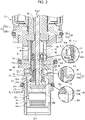
- FIG. 1 is a capacity control valve.
- the capacity control valve 1 mainly includes a valve body 10, a valve element 20, a pressure-sensitive element 24, and a solenoid 30.
- the valve body 10 is composed of a metal such as brass, iron, aluminum, stainless steel, or a synthetic resin material, or the like.
- the valve body 10 is a hollow cylindrical member having a through hole that extends through it in an axial direction with a first valve chest 14, a second valve chest 15 adjacent to the first valve chest 14, and a third valve chest 16 adjacent to the second valve chest 15 continuously disposed in sections of the through hole.
- Second communication passages 12 are connected to the second valve chest 15.
- the second communication passages 12 are configured to communicate with the interior of a discharge chamber (not shown) of the variable capacity compressor so that the opening and closing of the capacity control valve 1 allows fluid under a discharge pressure Pd (a second pressure according to the present invention) to flow from the second valve chest 15 into the third valve chest 16.
- Pd a second pressure according to the present invention
- Third communication passages 13 are connected to the third valve chest 16.
- the third communication passages 13 communicate with a control chamber (not shown) of the variable capacity compressor so that the opening and closing of the capacity control valve 1 causes the fluid under the discharge pressure Pd flowing from the second valve chest 15 into the third valve chest 16 to flow out to the control chamber (the crank chamber) of the variable capacity compressor, or causes fluid under a control chamber pressure Pc (a third pressure according to the present invention) flowing into the third valve chest 16 to flow out to a suction chamber of the variable capacity compressor through an intermediate communication passage 29 described later and the first valve chest 14.
- first communication passages 11 are connected to the first valve chest 14.
- the first communication passages 11 guide fluid under a suction pressure Ps (a first pressure according to the present invention) from the suction chamber of the variable capacity compressor to the pressure-sensitive element 24 through the intermediate communication passage 29 described later so as to control the suction pressure of the compressor to a set value.
- Ps a first pressure according to the present invention
- a hole 18 is continuously formed between the first valve chest 14 and the second valve chest 15, the hole 18 having a diameter smaller than these chests.
- the hole 18 slides in relation to a labyrinth 21f described later to form a seal portion to seal a gap between the first valve chest 14 and the second valve chest 15.
- a valve hole 17 is continuously provided between the second valve chest 15 and the third valve chest 16, the valve hole 17 having a diameter smaller than these chests.
- a main valve seat 15a is formed around the valve hole 17 on the side of the second valve chest 15. The main valve seat 15a is separated from and comes into contact with a main valve portion 21c described later to control the opening and closing of the communication between the second valve chest 15 and the third valve chest 16.
- the pressure-sensitive element 24 is disposed inside the third valve chest 16.
- one end of a metal bellows 24a is joined to a partition adjustment portion 24f in a sealed manner.
- the bellows 24a is made of phosphor bronze, stainless steel or the like, and is designed to have a spring constant of a predetermined value.
- the interior space of the pressure-sensitive element 24 is a vacuum or contains air. Then, the pressure-sensitive element 24 is configured such that the pressure acts on an effective pressure-receiving area of the bellows 24a of the pressure-sensitive element 24 so as to operate to extend and contract the pressure-sensitive element 24.
- a head portion 24c is disposed on the free end side of the pressure-sensitive element 24, and an auxiliary valve seat 24d is formed in the head portion 24c.
- the auxiliary valve seat 24d comes into contact with and is separated from an auxiliary valve portion 23d described later so as to control the opening and closing of the communication between the third valve chest 16 and the intermediate communication passage 29.
- a flange portion 24h is formed in the head portion 24c of the pressure-sensitive element 24 and is pressed by a rod 36 of the solenoid 30 described later.
- the pressure-sensitive element 24 extends and contracts by being directly pressed by the rod 36 so that the auxiliary valve portion 23d is opened and closed. As described later, the pressure-sensitive element 24 extends and contracts according to the suction pressure Ps guided to the pressure-sensitive element 24 through the intermediate communication passage 29, and extends and contracts by the pressing force of the rod 36.
- the partition adjustment portion 24f of the pressure-sensitive element 24 is hermetically fitted and fixed so as to seal off the third valve chest 16 of the valve body 10. If the partition adjustment portion 24f is screwed and fixed with a set screw (not shown), the spring force of the compression spring arranged in parallel within the bellows 24a or the bellows 24a can be axially moved and adjusted.
- the first communication passages 11, the second communication passages 12, and the third communication passages 13 are, respectively, two to six in number, for example, and are spaced evenly around a peripheral surface of the valve body 10, extending therethrough. Furthermore, mounting grooves for O-rings are provided on the outer peripheral surface of the valve body 10 at three locations spaced apart in the axial direction. In the respective mounting grooves, O-rings 47, 48, and 49 are mounted for sealing a gap between the valve body 10 and a mounting hole (not shown) of a casing that is fitted onto the valve body 10, and respective flow paths of the first communication passages 11, the second communication passages 12, and the third communication passages 13 are configured as independent flow paths.
- the valve element 20 mainly includes a main valve element 21 and an adapter 23 which are formed of a hollow cylindrical member.
- the main valve element 21 is a hollow cylindrical member, and the labyrinth 21f is formed at a substantially central portion of the outer peripheral portion in the axial direction of the main valve element 21.
- the labyrinth 21f slides in relation to the hole 18 formed between the side of the first valve chest 14 and the side of the second valve chest 15 to form a seal portion to seal the gap between the first valve chest 14 and the second valve chest 15.
- the first valve chest 14 and the second valve chest 15 are configured as independent valve chests.
- the main valve element 21 is arranged on the side of the first valve chest 14 and the side of the second valve chest 15 with the labyrinth 21f interposed therebetween.
- the main valve portion 21c is formed at an end of the main valve element 21 arranged in the second valve chest 15, and the main valve portion 21c is separated from and comes into contact with the main valve seat 15a to control the opening and closing of the valve hole 17 that communicates the second valve chest 15 and the third valve chest 16.
- the main valve portion 21c and the main valve seat 15a constitute a main valve 27.
- a shutoff valve portion 21a is formed at an end of the main valve element 21 arranged in the first valve chest 14.
- the shutoff valve portion 21a comes into contact with an end 32c of a core 32 to shut off the communication between the intermediate communication passage 29 and the first valve chest 14 when the solenoid 30 is turned off as described later.
- the shutoff valve portion 21a and the end 32c of the core 32 constitute a shutoff valve 26.
- the shutoff valve portion 21a and the main valve portion 21c of the valve element 20 are formed so as to perform opening and closing operations in opposite directions.
- the adapter 23 is a hollow cylindrical member, and mainly includes a large diameter portion 23c formed with a large diameter, and a cylindrical portion 23e formed with a smaller diameter than the large diameter portion 23c.
- the cylindrical portion 23e is fitted to the open end of the main valve element 21 on the side of the main valve portion 21c to constitute the valve element 20.
- the intermediate communication passage 29 is formed inside the main valve element 21 and the adapter 23, that is, inside the valve element 20 to extend through it in the axial direction.
- auxiliary valve portion 23d is formed in the large diameter portion 23c of the adapter 23, and the auxiliary valve portion 23d comes into contact with and is separated from the auxiliary valve seat 24d formed in the head portion 24c of the pressure-sensitive element 24 to open and close the communication between the third valve chest 16 and the intermediate communication passage 29.
- the auxiliary valve portion 23d and the auxiliary valve seat 24d constitute the auxiliary valve 28.
- the solenoid 30 includes the rod 36, a plunger case 38, an electromagnetic coil 31, a core 32 including a center post 32a and a base member 32b, a plunger 35, a plate 34, and a solenoid case 33.
- the plunger case 38 is a bottomed hollow cylindrical member with one end open.
- the plunger 35 is arranged so as to be axially movable with respect to the plunger case 38 between the plunger case 38 and the center post 32a arranged inside the plunger case 38.
- the core 32 is fitted to the valve body 10 and is arranged between the plunger 35 and the valve body 10.
- the rod 36 is arranged so as to extend through the center post 32a of the core 32 and the valve element 20 arranged in the valve body 10, and there is a gap between the road 36, and a through hole 32e of the center post 32a of the core 32 and the intermediate communication passage 29 of the valve element 20, so that the road 36 can move relative to the core 32 and the valve element 20. Furthermore, one end 36e of the rod 36 is connected to the plunger 35, and a pressing portion 36d at the other end is in contact with the flange portion 24h of the head portion 24 c of the pressure-sensitive element 24. Thus, the rod 36 can be driven by an electromagnetic force generated between the core 32 and the plunger 35, and the rod 36 can directly press the pressure-sensitive element 24 to extend and contract the pressure-sensitive element 24.
- the open end of the plunger case 38 is fixed to an inner periphery of the base member 32b of the core 32 in a sealed manner
- the solenoid case 33 is fixed to an outer periphery of the base member 32b in a sealed manner.
- the electromagnetic coil 31 is arranged in a space surrounded by the plunger case 38, the base member 32b of the core 32, and the solenoid case 33, and does not come into contact with the refrigerant, allowing a decrease in insulation resistance to be prevented.
- the spacer 41 is a cylindrical member having a base 41e and a flange 41c extending in the axial direction from the base 41e, and is fitted and fixed to an inner-diameter portion of the valve element 20.
- the flange 41c is arranged in contact with a stepped portion 21b formed between the shutoff valve portion 21a and the main valve portion 21c at the inner diameter portion of the valve element 20 to form a gap between the stepped portion 21b and the spacer 41.
- a retaining ring 42 (a locking portion according to the present invention) fixed to the rod 36 is arranged.
- the spacer 41 has a flow hole 41d through which the refrigerant flows.
- the retaining ring 42 fixed to the rod 36 comes into contact with a main valve portion side end 41b of the base 41e of the spacer 41 fixed to the valve element 20, so that the driving force of the rod 36 of the solenoid 30 acts on the valve element 20 as a force in a valve opening direction of the main valve portion 21c.
- the retaining ring 42 fixed to the rod 36 comes into contact with the stepped portion 21b of the valve element 20, so that the driving force of the solenoid 30 acts on the valve element 20 as a force in a valve closing direction of the main valve portion 21c.
- a spring 43 (a first biasing member according to the present invention) and a spring 44 (a second biasing member according to the present invention) that are disposed with the retaining ring 42 interposed therebetween will be described.
- the spring 43 is disposed between the core 32 and the spacer 41 of the valve element 20. Specifically, one end of the spring 43 is in contact with the core 32, and the other end is in contact with a shutoff valve portion side end 41a of the base 41e of the spacer 41 provided in the valve element 20.
- the biasing force of the spring 43 acts on the valve element 20 in the valve closing direction of the main valve portion 21c.
- the spring 44 is disposed between the pressure-sensitive element 24 and the rod 36. Specifically, one end of the spring 44 is in contact with a stepped portion 36f formed on the rod 36 between the pressing portion 36d of the rod 36 and the retaining ring 42, and the other end is in contact with the flange portion 24h of the head portion 24c of the pressure-sensitive element 24.
- the biasing force of the spring 44 acts on the valve element 20 through the retaining ring 42 and the spacer 41 in the valve opening direction of the main valve portion 21c.
- the spring constant of the spring 44 is set to be larger than the spring constant of the spring 43, and the biasing force of the spring 44 is larger than the biasing force of the spring 43.
- a flow path from the third valve chest 16 to the first valve chest 14 through the intermediate communication passage 29 is hereinafter referred to as a "Pc-Ps flow path”.
- a flow path from the second valve chest 15 to the third valve chest 16 through the valve hole 17 is hereinafter referred to as a "Pd-Pc flow path”.
- each valve first, when the rod 36 is in a stopped state, the rod is in operation, and the rod is then stopped will be described.
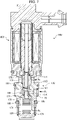
- the solenoid 30 when the solenoid 30 is in a non-energized state, the resultant force of the biasing force of the pressure-sensitive element 24 and the biasing force of the spring 44 exceeds the biasing force of the spring 43. Therefore, the rod 36 is pushed up to the side of the spring 43, and the retaining ring 42 comes into contact with the spacer 41, and the valve element 20 moves in the valve opening direction of the main valve portion 21c to fully open the main valve portion 21c, and the shutoff valve portion 21a comes into contact with the end 32c of the core 32 to fully close the shutoff valve portion 21a (see FIG. 3 ).
- the rod 36 is gradually driven in an advancing direction (in the direction in which the rod 36 projects outward from the end 32c of the core 32).
- the spacer 41 is pressed downward by the spring 43, the retaining ring 42 fixed to the rod 36 and the spacer 41 fixed to the valve element 20 move in contact with each other, and the rod 36 and the valve element 20 move integrally.
- the shutoff valve portion 21a opens from the fully closed state, and the main valve portion 21c is gradually narrowed from the fully open state (see FIG. 1 ).
- the shutoff valve portion 21a When the rod 36 is further driven in the advancing direction, the shutoff valve portion 21a is brought into the fully open state, and the main valve portion 21c comes into contact with the main valve seat 15a to be brought into the fully closed state, so that the movement of the valve element 20 is stopped.
- the retaining ring 42 When the rod 36 is further driven in the advancing direction from this state, the retaining ring 42 is separated from the spacer 41, the rod 36 moves relative to the main valve element 21, and the pressing portion 36d of the rod 36 presses the flange portion 24h of the pressure-sensitive element 24 to contract the sensitive element 24, which allows the auxiliary valve portion 23d to be forcibly opened (see FIG. 2 ).
- the retaining ring 42 comes into contact with the stepped portion 21b of the valve element 20, so that the rod 36 is stopped.
- the control state is a state in which the auxiliary valve portion 23d is in a closed state, and the main valve portion 21c is set to have a predetermined opening by the solenoid 30 so that the pressure in the suction chamber of the variable capacity compressor is controlled to reach the set value Pset.
- the fluid under the suction pressure Ps flowing from the suction chamber of the variable capacity compressor to the first valve chest 14 through the first communication passages 11 acts on the pressure-sensitive element 24 through the intermediate communication passage 29.
- the main valve portion 21c is stopped at a position where the force of the spring 43 in the valve closing direction, the force of the spring 44 in the valve opening direction, the force of the solenoid 30, and the biasing force of the pressure-sensitive element 24 that extends and contracts according to the suction pressure Ps are balanced.
- the suction pressure Ps may fluctuate due to disturbance or the like. For example, when the pressure Ps in the suction chamber becomes higher than the set value Pset, the pressure-sensitive element 24 contracts and the opening of the main valve portion 21c becomes smaller.
- the Pd-Pc flow path is narrowed, so that the amount of refrigerant under the discharge pressure Pd flowing from the discharge chamber to the crank chamber reduces and the pressure in the crank chamber decreases.
- the angle of inclination of the swash plate of the compressor becomes larger, and the discharge capacity of the compressor increases, causing the discharge pressure to decrease.
- the pressure-sensitive element 24 extends and the opening of the main valve portion 21c becomes larger.
- the Pd-Pc flow path is extended, so that the amount of refrigerant under the discharge pressure Pd flowing from the discharge chamber to the crank chamber increases, and the pressure in the crank chamber increases.
- the angle of inclination of the swash plate of the compressor becomes smaller, causing the discharge capacity of the compressor to reduce and causing the discharge pressure to increase.
- the capacity control valve 1 can control the pressure in the suction chamber of the variable capacity compressor so as to reach the set value Pset.
- a liquid refrigerant discharge state of the capacity control valve 1 will be described with reference to FIG. 2 .
- a liquid refrigerant a refrigerant that has been liquefied by cooling while the compressor is inoperative
- the pressure in the third valve chest 16 communicating with the crank chamber becomes higher and the suction pressure Ps also becomes higher.
- the pressure-sensitive element 24 contracts and the valve element 20 is pressed downward by the spring 43, so that the main valve portion 21c is brought into a closed state and the auxiliary valve portion 23d is brought into an open state. Even in this state, the liquid refrigerant can be discharged from the crank chamber to the suction chamber through the Pc-Ps flow path. However, as the discharge of the liquid refrigerant discharge progresses, the pressure in the third valve chest 16 and the suction pressure Ps gradually decrease, so that the opening of the auxiliary valve portion 23d gradually becomes smaller, resulting in an increase in time to complete the discharge of the liquid refrigerant.
- the solenoid 30 is driven in the advancing direction, and the pressure-sensitive element 24 is pressed by the rod 36 to forcibly bring the auxiliary valve portion 23d into the fully open state.
- the auxiliary valve portion 23d is kept in the fully open state, so that the opening of the auxiliary valve portion 23d does not change from the start of the liquid refrigerant discharge to the completion of the liquid refrigerant discharge, allowing the liquid refrigerant to be discharged from the crank chamber to the suction chamber thorough the Pc-Ps flow path in a short time.
- the solenoid 30 is turned off, and a magnetic attractive force Fsol between the core 32 and the plunger 35 is set to zero.
- the main force acting on the valve element 20 is the biasing force of the spring 44 and the spring 43.
- the biasing force of the spring 44 is set to be larger than the biasing force of the spring 43, the rod 36 is pushed up by the biasing force of the spring 44, the retaining ring 42 comes into contact with the spacer 41 so that the valve element 20 is driven, and the main valve portion 21c is fully opened.
- the main valve portion 21c is fully opened, the amount of refrigerant flowing from the discharge chamber of the compressor to the crank chamber through the Pd-Pc flow path increases and the pressure Pc in the crank chamber becomes higher, so that the compressor is operated with the minimum capacity.
- the rod 36 moves integrally with the valve element 20 while the main valve portion 21c is brought from the fully open state into the fully closed state, and after the main valve portion 21c is fully closed, the rod 36 moves relative to the valve element 20 to press the sensitive element 24, allowing the auxiliary valve portion 23d to be opened. That is, one rod 36 can open and close the main valve portion 21c and the auxiliary valve portion 23d, which are different.
- the spring constant of the spring 44 is set to be larger than the spring constant of the spring 43, and the biasing force of the spring 44 is larger than the biasing force of the spring 43, the opening and closing states of the main valve portion 21c and the auxiliary valve portion 23d can be opened and closed in any combination.
- the main valve portion 21c can be opened while the auxiliary valve portion 23d be opened, the main valve portion 21c can be opened while the auxiliary valve portion 23d be closed, the main valve portion 21c can be closed while the auxiliary valve portion 23d be opened, and the main valve portion 21c can be closed while the auxiliary valve portion 23d be closed.
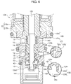
- FIG. 4 reference numeral 100 is a capacity control valve.
- the capacity control valve 100 mainly includes a valve body 110, a valve element 120, a pressure-sensitive element 124, and a solenoid 130.
- the capacity control valve 100 mainly includes the valve body 110, the valve element 120, the pressure-sensitive element 124, and the solenoid 130.
- the valve body 110 is composed of a metal such as brass, iron, aluminum, stainless steel, or a synthetic resin material, or the like.
- the valve body 110 is a hollow cylindrical member having a through hole that extends through it in an axial direction with a first valve chest 114, a second valve chest 115 adjacent to the first valve chest 114, and a third valve chest 116 adjacent to the second valve chest 115 continuously disposed in sections of the through hole.
- Second communication passage 112 are connected to the second valve chest 115.
- the second communication passages 112 are configured to communicate with the inside of a discharge chamber (not shown) of the variable capacity compressor so that the opening and closing of the capacity control valve 100 allows fluid under the discharge pressure Pd to flow from the second valve chest 115 into the third valve chest 116.
- Third communication passage 113 are connected to the third valve chest 116.
- the third communication passages 113 communicate with a control chamber (not shown) of the variable capacity compressor so that the opening and closing of the capacity control valve 100 causes the fluid under the discharge pressure Pd flowing from the second valve chest 115 into the third valve chest 116 to flow out to the control chamber (the crank chamber) of the variable capacity compressor, or causes fluid under the control chamber pressure Pc flowing into the third valve chest 116 to flow out to a suction chamber of the variable capacity compressor through an intermediate communication passage 129 described later and the first valve chest 114.
- first communication passages 111 are connected to the first valve chest 114.
- the first communication passages 111 guide fluid under the suction pressure Ps from the suction chamber of the variable capacity compressor to the pressure-sensitive element 124 through the intermediate communication passage 129 described later to control the suction pressure of the compressor to a set value.
- a hole 118 is continuously formed between the first valve chest 114 and the second valve chest 115, the hole 118 having a diameter smaller than these chests.
- the hole 118 slides in relation to a labyrinth 121f described later to form a seal portion to seal a gap between the first valve chest 114 and the second valve chest 115.
- a valve hole 117 is continuously provided between the second valve chest 115 and the third valve chest 116, the valve hole 117 having a diameter smaller than these chests.
- a main valve seat 115a is formed around the valve hole 117 on the side of the second valve chest 115. The main valve seat 115a is separated from and comes into contact with a main valve portion 121c described later to control the opening and closing of the communication between the second valve chest 115 and the third valve chest 116.
- the pressure-sensitive element 124 is disposed inside the third valve chest 116.
- one end of a metal bellows 124a is joined to a partition adjustment portion 124f in a sealed manner.
- the bellows 124a is made of phosphor bronze, stainless steel or the like, and is designed to have a spring constant of a predetermined value.
- the interior space of the pressure-sensitive element 124 is a vacuum or contains air. Then, the pressure-sensitive element 124 is configured such that the pressure acts on an effective pressure-receiving area of the bellows 124a of the pressure-sensitive element 124 so as to operate to extend and contract the pressure-sensitive element 124.
- a head portion 124c is disposed on the free end side of the pressure-sensitive element 124, and an auxiliary valve seat 124d is formed in the head portion 124c.
- the auxiliary valve seat 124d comes into contact with and is separated from an auxiliary valve portion 123d described later to control the opening and closing of the communication between the third valve chest 116 and the intermediate communication passage 129.
- the head portion 124c of the pressure-sensitive element 124 extends and contracts by being pressed by a rod 136 of the solenoid 130 described later so that the auxiliary valve portion 123d is opened and closed.
- the pressure-sensitive element 124 extends and contracts according to the suction pressure Ps guided to the pressure-sensitive element 124 through the intermediate communication passage 129, and extends and contracts by the pressing force of the rod 136.
- the partition adjustment portion 124f of the pressure-sensitive element 124 is hermetically fitted and fixed so as to seal off the third valve chest 116 of the valve body 110. If the partition adjustment portion 124f is screwed and fixed with a set screw (not shown), the spring force of the compression spring arranged in parallel within the bellows 124a or the bellows 124a can be axially moved and adjusted.
- the first communication passages 111, the second communication passages 112, and the third communication passages 113 are, respectively, two to six in number, for example, and are spaced evenly around a peripheral surface of the valve body 110, extending therethrough. Furthermore, mounting grooves for O-rings are provided on the outer peripheral surface of the valve body 110 at three locations spaced apart in the axial direction. In the respective mounting grooves, O-rings 147, 148, and 149 are mounted for sealing a gap between the valve body 110 and a mounting hole (not shown) of a casing that is fitted onto the valve body 110. Respective flow paths of the first communication passages 111, the second communication passages 112, and the third communication passages 113 are configured as independent flow paths.
- the valve element 120 mainly includes a main valve element 121 and an adapter 123, which are formed of a hollow cylindrical member.
- the main valve element 121 is a hollow cylindrical member, and the labyrinth 121f is formed at a substantially central portion of the outer peripheral portion in the axial direction of the main valve element 121.
- the labyrinth 121f slides in relation to the hole 118 formed between the side of the first valve chest 114 and the side of the second valve chest 115 to form a seal portion to seal the gap between the first valve chest 114 and the second valve chest 115.
- the first valve chest 114 and the second valve chest 115 are configured as independent valve chests.
- the main valve element 121 is arranged on the side of the first valve chest 114 and the side of the second valve chest 115 with the labyrinth 121f interposed therebetween.
- the main valve portion 121c is formed at an end of the main valve element 121 arranged in the second valve chest 115, and the main valve portion 121c is separated from and comes into contact with the main valve seat 115a to control the opening and closing of the valve hole 117 that communicates the second valve chest 115 and the third valve chest 116.
- the main valve portion 121c and the main valve seat 115a constitute a main valve 127.
- a shutoff valve portion 121a is formed at an end of the main valve element 121 arranged in the first valve chest 114.
- the shutoff valve portion 121a comes into contact with an end 132c of a core 132 when the solenoid 130 is turned off as described later to shut off the communication between the intermediate communication passage 129 and the first valve chest 114.
- the shutoff valve portion1 121a and the end 132c of the core 132 constitute a shutoff valve 126.
- the shutoff valve portion 121a and the main valve portion 121c are formed so as to perform opening and closing operations in opposite directions.
- the adapter 123 is a hollow cylindrical member and mainly includes a large diameter portion 123c formed with a large diameter, and a cylindrical portion 123e formed with a smaller diameter than the large diameter portion 123c.
- the cylindrical portion 123e is fitted to the open end of the main valve element 121 on the side of the main valve portion 121c to constitute the valve element 120.
- the intermediate communication passage 129 is formed inside the main valve element 121 and the adapter 123, that is, inside the valve element 120 to extend through it in the axial direction.
- auxiliary valve portion 123d is formed at the distal end of the large diameter portion 123c, and the auxiliary valve portion 123d comes into contact with and is separated from the auxiliary valve seat 124d of the pressure-sensitive element 124 to open and close the communication between the third valve chest 116 and the intermediate communication passage 129.
- the auxiliary valve portion 123d and the auxiliary valve seat 124d constitute the auxiliary valve 128.
- the solenoid 130 includes the rod 136, a plunger case 138, an electromagnetic coil 131, a core 132 including a center post 132a and a base member 132b, a plunger 135, a plate 134, and a solenoid case 133.
- the plunger case 138 is a bottomed hollow cylindrical member with one end open.
- the plunger 135 is arranged so as to be axially movable with respect to the plunger case 138 between the plunger case 138 and a center post 132a arranged inside the plunger case 138.
- the core 132 is fitted to the valve body 110 and is arranged between the plunger 135 and the valve body 110.
- the rod 136 is arranged so as to extend through the center post 132a of the core 132 and the valve element 120 arranged in the valve body 110, and there is a gap between the road 136, and a through hole 132e of the center post 132a of the core 132 and the intermediate communication passage 129 of the valve element 120, so that the road 136 can move relative to the core 132 and the valve element 120. Furthermore, one end 136e of the rod 136 is connected to the plunger 135, and a pressing portion 136d at the other end is in contact with the head portion 124c of the pressure-sensitive element 124. Thus, the rod 136 can be driven by an electromagnetic force generated between the core 132 and the plunger 135, and the rod 136 can directly press the pressure-sensitive element 124 to extend and contract the pressure-sensitive element 124.
- a spring 137 (a second biasing member according to the present invention) is arranged between the core 132 and the plunger 135 for biasing the plunger 135 so that the plunger 135 is separated from the core 132.
- the biasing force of the spring 137 acts in a direction to open the main valve portion 121c of the valve element 120.
- the open end of the plunger case 138 is fixed to an inner periphery of the base member 132b of the core 132 in a sealed manner
- the solenoid case 133 is fixed to an outer periphery of the base member 132b in a sealed manner.
- the electromagnetic coil 131 is arranged in a space surrounded by the plunger case 138, the base member 132b of the core 132, and the solenoid case 133, and does not come into contact with the refrigerant, allowing a decrease in insulation resistance to be prevented.
- a retaining ring 142 (a locking portion according to the present invention) constituting a part of the rod 136 will be described.
- the retaining ring 142 is a disk-shaped member, and is fitted and fixed to the rod 136 so as to be located between the adapter 123 and the head portion 124c of the pressure-sensitive element 124.
- the retaining ring 142 comes into contact with the adapter 123 of the valve element 120, so that the driving force of the rod 136 of the solenoid 130 acts on the valve element 120 as a force in the valve opening direction of the main valve portion 121c.
- the retaining ring 142 fixed to the rod 136 comes into contact with the head portion 124c of the pressure-sensitive element 124, so that the driving force of the rod 136 of the solenoid 130 directly presses the pressure-sensitive element 124 to extend and contract the pressure-sensitive element 124.
- a protrusion 124h is formed at the central portion of the head portion 124c of the pressure-sensitive element 124, and a protrusion (not shown) is formed also at the central portion of the partition adjustment portion 124f of the pressure-sensitive element 124 facing the auxiliary valve seat 124d.
- the spring 143 is disposed between the solenoid 130 and the valve element 120. Specifically, one end of the spring 143 is in contact with the core 132, and the other end is in contact with a stepped portion 121b formed between the shutoff valve portion 121a and the labyrinth 121f of the valve element 120. Thus, the biasing force of the spring 143 acts in a direction to close the main valve portion 121c of the valve element 120.
- the spring constant of the spring 137 (the second biasing member) provided between the core 132 and the plunger 135 is set larger than the spring constant of the spring 143 (the first biasing member), and the biasing force of the spring 137 is larger than the biasing force of the spring 143.
- a flow path from the third valve chest 116 to the first valve chest 114 through the intermediate communication passage 129 is hereinafter referred to as "Pc-Ps flow path”.
- a flow path from the second valve chest 115 to the third valve chest 116 through the valve hole 117 is hereinafter referred to as "Pd-Pc flow path”.
- each valve first, when the rod 136 is in a stopped state, the rod 136 is in operation, and the rod 136 is then stopped will be described with reference to FIG. 6 .
- the solenoid 130 when the solenoid 130 is in a non-energized state, the resultant force of the biasing force of the pressure-sensitive element 124 and the biasing force of the spring 137 ( FIG. 4 ) exceeds the biasing force of the spring 143.
- the rod 136 is pushed upward, and the retaining ring 142 comes into contact with the adapter 123, so that the adapter 123 is pressed to fully open the main valve portion 121c, and the shutoff valve portion 121a comes into contact with the end 132c of the core 132 to fully close the shutoff valve portion 121a.
- the rod 136 is gradually driven in an advancing direction (in the direction in which the rod 136 projects outward from the end 132c of the core 132).
- the valve element 120 is pressed downward by the spring 143, the retaining ring 142 fixed to the rod 136 and the adapter 123 of the valve element 120 move in contact with each other, and the rod 136 and the valve element 120 also move integrally.
- the shutoff valve portion 121a opens from the fully closed state, and the opening of the main valve portion 121c is gradually narrowed (see FIG. 4 ).
- the retaining ring 142 of the rod 136 comes into contact with the head portion 124c of the pressure-sensitive element 124, and presses the head portion 124c to contract the pressure-sensitive element 124, which allows the auxiliary valve portion 123d to be forcibly opened.
- the pressure-sensitive element 124 is contracted by a predetermined amount, the protrusion 124h and the protrusion (not shown) of the partition adjustment portion 124f come into contact with each other so that the deformation of the pressure-sensitive element 124 is restricted and the movement of the rod 136 is also stopped (see FIG. 5 ).
- the pressing portion 136d of the rod 136 may press the head portion 124c of the pressure-sensitive element 124 to contract the pressure-sensitive element 124, causing the auxiliary valve portion 123d to be forcibly opened.
- the control state is a state in which the auxiliary valve portion 123d is in a closed state, and the main valve portion 121c is set to have a predetermined opening by the solenoid 130 so that the pressure in the suction chamber of the variable capacity compressor is controlled to reach the set value Pset.
- the fluid under the suction pressure Ps flowing from the suction chamber of the variable capacity compressor to the first valve chest 114 through the first communication passages 111 acts on the pressure-sensitive element 124 through the intermediate communication passage 129.
- the main valve portion 121c is stopped at a position where the force of the spring 143 in the valve closing direction, the force of the spring 137 in the valve opening direction, the force of the solenoid 130, and the force of the pressure-sensitive element 124 that extends and contracts according to the suction pressure Ps are balanced.
- the pressure Ps in the suction chamber may become higher than the set value Pset due to disturbance or the like.
- the pressure-sensitive element 124 contracts and the opening of the main valve portion 121c becomes smaller.
- the Pd-Pc flow path is narrowed, so that the amount of refrigerant under the discharge pressure Pd flowing from the discharge chamber to the crank chamber reduces and the pressure in the crank chamber decreases.
- the angle of inclination of the swash plate of the compressor becomes larger, and the discharge capacity of the compressor increases, causing the discharge pressure to decrease.
- the pressure-sensitive element 124 extends and the opening of the main valve portion 121c becomes larger.
- the Pd-Pc flow path is extended, so that the amount of refrigerant under the discharge pressure Pd flowing from the discharge chamber to the crank chamber increases, and the pressure in the crank chamber increases.
- the capacity control valve 100 can control the pressure in the suction chamber of the variable capacity compressor so as to reach the set value Pset.
- the solenoid 130 When the solenoid 130 is driven in the advancing direction, the main valve portion 121c is brought into the fully closed state, and the retaining ring 142 of the rod 136 presses the pressure-sensitive element 124 to forcibly open the auxiliary valve portion 123d, so that the auxiliary valve portion 123d is brought into the fully open state.
- the pressure-sensitive element 124 is pressed by the rod 136 so that the auxiliary valve portion 123d is kept in the fully open state.
- the opening of the auxiliary valve portion 123d does not change from the start of the liquid refrigerant discharge to the completion of the liquid refrigerant discharge and can be kept in the fully open state, allowing the liquid refrigerant to be discharge from the crank chamber to the suction chamber thorough the Pc-Ps flow path in a short time.
- the solenoid 130 is turned off, and a magnetic attractive force Fsol between the core 132 and the plunger 135 is set to zero.
- the main force acting on the valve element 120 is the biasing force of the spring 137 and the spring 143.
- the biasing force of the spring 137 is set to be larger than the biasing force of the spring 143.
- the rod 136 is pushed up by the biasing force of the spring 137, the retaining ring 142 comes into contact with the adapter 123 so that the valve element 120 is driven, and the main valve portion 121c is fully opened.
- the main valve portion 121c is fully opened, the amount of refrigerant flowing from the discharge chamber of the compressor to the crank chamber through the Pd-Pc flow path increases and the pressure Pc in the crank chamber increases, so that the compressor is operated with the minimum capacity.
- the main valve portion 121c is brought into the fully open state to increase the amount of refrigerant under the pressure Pd flowing from the discharge chamber of the compressor to the crank chamber through the Pd-Pc flow path, allowing the compressor to operate with a minimum capacity and perform the operation for reducing the load on the engine.
- the rod 136 moves integrally with the valve element 120 while the main valve portion 121c is brought from the fully open state into the fully closed state, and after the main valve portion 121c is fully closed, the rod 136 moves relative to the valve element 120 to press the sensitive element 124, allowing the auxiliary valve portion 123d to be opened. That is, one rod 136 can open and close the main valve portion 121c and the auxiliary valve portion 123d, which are different.
- the opening and closing states of the main valve portion 121c and the auxiliary valve portion 123d can be opened and closed in any state. That is, the main valve portion 121c can be opened while the auxiliary valve portion 123d be opened, the main valve portion 121c can be opened while the auxiliary valve portion 123d be closed, while the main valve portion 121c can be closed the auxiliary valve portion 123d be opened, while the main valve portion 121c can be closed and the auxiliary valve portion 123d be closed.
- the spring 143 is arranged on the outer peripheral side of the main valve element 121 in the first valve chest 114, but is not limited thereto.
- it may be arranged on the inner peripheral side of the main valve element 121 in the first valve chest 114 so that its one end is in contact with the core 132 and the other end is in contact with the valve element 120.
- a first pressure in the first valve chest 14 (114) is the suction pressure Ps of the variable capacity compressor
- a second pressure in the second valve chest 15 (115) is the discharge pressure Pd of the variable capacity compressor
- a third pressure in the third valve chest 16 (116) is the pressure Pc in the crank chamber of the variable capacity compressor, but is not limited to this.
- the first pressure in the first valve chest 14 (114) may be the pressure Pc in the crank chamber of the variable capacity compressor
- the second pressure in the second valve chest 15 (115) be the discharge pressure Pd of the variable capacity compressor
- the third pressure in the third valve chest 16 (116) be the suction pressure Ps of the variable capacity compressor, so that the present invention can be applied to various variable capacity compressors.
Landscapes
- Engineering & Computer Science (AREA)
- General Engineering & Computer Science (AREA)
- Mechanical Engineering (AREA)
- Physics & Mathematics (AREA)
- Electromagnetism (AREA)
- Power Engineering (AREA)
- General Physics & Mathematics (AREA)
- Automation & Control Theory (AREA)
- Compressors, Vaccum Pumps And Other Relevant Systems (AREA)
- Magnetically Actuated Valves (AREA)
Claims (9)
- Volumenstromsteuerungsventil (1; 100) zum Steuern einer Strömungsrate oder eines Drucks eines Kompressors mit variabler Leistung in Übereinstimmung mit einer Ventilöffnung einer Ventileinheit, wobei das Ventil (1; 100) Folgendes aufweist:einen Ventilkörper (10; 110), der erste Verbindungsdurchlässe (11; 111), die ein Fluid unter einem ersten Druck (Ps; Pc) durchlassen, zweite Verbindungsdurchlässe (12; 112), die neben den ersten Verbindungdurchlässen (11; 111) angeordnet sind und ein Fluid unter einem zweiten Druck (Pd) durchlassen, dritte Verbindungsdurchlässe (13; 113), die ein Fluid unter einem dritten Druck (Pc; Ps) durchlassen, sowie einen Hauptventilsitz (15a; 115a) umfasst, der in einem Ventilloch (17; 117) angeordnet ist, das die zweiten Verbindungsdurchlässe (12; 112) und die dritten Verbindungsdurchlässe (13; 113) verbindet;ein druckempfindliches Element (24; 124), das in dem Ventilkörper (10; 110) auf der Seite der dritten Verbindungsdurchlässe (13; 113) angeordnet ist und eingerichtet ist, sich auszudehnen und zusammenzuziehen;ein Ventilelement (20; 120), das einen Zwischenverbindungsdurchlass (29; 129), der die ersten Verbindungsdurchlässe (11; 111) und die dritten Verbindungsdurchlässe (13; 113) verbindet, einen Hauptventilabschnitt (21c; 121c), der sich von dem Hauptventilsitz (15a; 115a) entfernt und mit diesem in Kontakt gelangt, um das Ventilloch (17; 117) zu öffnen und zu schließen, sowie einen Hilfsventilabschnitt (23d; 123d) umfasst, der eingerichtet ist, den Zwischenverbindungsdurchlass (29; 129) zu öffnen und zu schließen;ein Elektromagnetventil (30; 130), das einen Stab (36; 136) antreibt;ein erstes Vorspannelement (43; 143), das eingerichtet ist, das Ventilelement (20; 120) in einer Ventilschließrichtung des Hauptventilabschnitts (21c; 121c) vorzuspannen; undein zweites Vorspannelement (44; 137), das eingerichtet ist, das Ventilelement (20; 120) in einer Ventilöffnungsrichtung des Hauptventilabschnitts (21c; 121c) vorzuspannen,dadurch gekennzeichnet, dassder Hilfsventilabschnitt (23d; 123d) eingerichtet ist, sich von einem Hilfsventilsitz (24d, 124d) zu entfernen und mit diesem in Kontakt zu gelangen, der auf einer Seite eines freien Endes des druckempfindlichen Elements (24, 124) vorgesehen ist, um den Zwischenverbindungsdurchlass (29; 129) zu öffnen und zu schließen, wobei das druckempfindliche Element (24; 124) eingerichtet ist, sich in Übereinstimmung mit dem ersten Druck (Ps; Pc), der durch den Zwischenverbindungsdurchlass (29; 129) geleitet wird, auszudehnen und zusammenzuziehen, undder Stab (36; 136) eingerichtet ist, das druckempfindliche Element (24; 124) zu pressen, indem er sich bezüglich dem Ventilelement (20; 120) bewegt, sodass sich der Hilfsventilabschnitt (23d; 123d) von dem Hilfsventilsitz (24d, 124d) des druckempfindlichen Elements (24; 124) entfernt, um den Zwischenverbindungsdurchlass (29; 129) zu öffnen.
- Volumenstromsteuerungsventil (1; 100) nach Anspruch 1, wobei eine Vorspannkraft des zweiten Vorspannelements (44; 137) größer ist als eine Vorspannkraft des ersten Vorspannelements (43; 143).
- Volumenstromsteuerungsventil (1; 100) nach Anspruch 1 oder 2, wobei das erste Vorspannelement (43; 143) zwischen dem Elektromagneten (30; 130) und dem Ventilelement (20; 120) angeordnet ist.
- Volumenstromsteuerungsventil (1; 100) nach einem der Ansprüche 1 bis 3, wobei das zweite Vorspannelement (44; 137) zwischen dem druckempfindlichen Element (24; 124) und dem Stab (36; 136) angeordnet ist.
- Volumenstromsteuerungsventil (1; 100) nach einem der Ansprüche 1 bis 3, wobeidas Elektromagnetventil (30; 130) ferner einen Kolben, der mit dem Stab (36; 136) verbunden ist, einen Kern (32; 132), der zwischen dem Kolben (35; 135) und dem Ventilkörper (10; 110) angeordnet ist, sowie eine elektromagnetische Spule (31; 131) umfasst, unddas zweite Vorspannelement (44; 137) zwischen dem Kolben (35; 135) und dem Kern (32; 132) angeordnet ist.
- Volumenstromsteuerungsventil (1; 100) nach einem der Ansprüche 1 bis 5, wobei der Stab (36; 136) einen Verriegelungsabschnitt (42; 142) umfasst, der sich von dem Ventilelement (20; 120) entfernt und mit diesem in Kontakt gelangt.
- Volumenstromsteuerungsventil (1; 100) nach einem der Ansprüche 1 bis 6, wobei der Stab (36; 136) einen Pressabschnitt (36d; 136d) umfasst, der das druckempfindliche Element (24; 124) presst.
- Volumenstromsteuerungsventil (1; 100) nach einem der Ansprüche 1 bis 7, wobei der erste Druck ein Ansaugdruck (Ps) des Kompressors mit variabler Leistung ist, der zweite Druck ein Ausstoßdruck (Pd) des Kompressors mit variabler Leistung ist, und der dritte Druck ein Druck (Pc) einer Kurbelkammer des Kompressors mit variabler Leistung ist.
- Volumenstromsteuerungsventil (1; 100) nach einem der Ansprüche 1 bis 7, wobei der erste Druck ein Druck (Pc) in einer Kurbelkammer des Kompressors mit variabler Leistung ist, der zweite Druck ein Ausstoßdruck (Pd) des Kompressors mit variabler Leistung ist, und der dritte Druck ein Ansaugdruck (Ps) des Kompressors mit variabler Leistung ist.
Applications Claiming Priority (2)
| Application Number | Priority Date | Filing Date | Title |
|---|---|---|---|
| JP2017220521 | 2017-11-15 | ||
| PCT/JP2018/041768 WO2019098149A1 (ja) | 2017-11-15 | 2018-11-12 | 容量制御弁及び容量制御弁の制御方法 |
Publications (3)
| Publication Number | Publication Date |
|---|---|
| EP3712433A1 EP3712433A1 (de) | 2020-09-23 |
| EP3712433A4 EP3712433A4 (de) | 2021-07-14 |
| EP3712433B1 true EP3712433B1 (de) | 2022-07-06 |
Family
ID=66539606
Family Applications (1)
| Application Number | Title | Priority Date | Filing Date |
|---|---|---|---|
| EP18879108.1A Active EP3712433B1 (de) | 2017-11-15 | 2018-11-12 | Kapazitätssteuerventil und verfahren zur steuerung des kapazitätssteuerungsventils |
Country Status (6)
| Country | Link |
|---|---|
| US (2) | US11542931B2 (de) |
| EP (1) | EP3712433B1 (de) |
| JP (1) | JP7094642B2 (de) |
| KR (1) | KR102336134B1 (de) |
| CN (2) | CN114687984B (de) |
| WO (1) | WO2019098149A1 (de) |
Families Citing this family (29)
| Publication number | Priority date | Publication date | Assignee | Title |
|---|---|---|---|---|
| CN110192052B (zh) | 2017-01-26 | 2020-09-22 | 伊格尔工业股份有限公司 | 容量控制阀 |
| US11542930B2 (en) | 2017-02-18 | 2023-01-03 | Eagle Industry Co., Ltd. | Capacity control valve |
| CN114687984B (zh) | 2017-11-15 | 2024-12-31 | 伊格尔工业股份有限公司 | 容量控制阀 |
| JP7083844B2 (ja) | 2017-11-30 | 2022-06-13 | イーグル工業株式会社 | 容量制御弁及び容量制御弁の制御方法 |
| KR102441855B1 (ko) | 2017-12-08 | 2022-09-08 | 이구루코교 가부시기가이샤 | 용량 제어 밸브 및 용량 제어 밸브의 제어 방법 |
| US11542929B2 (en) | 2017-12-14 | 2023-01-03 | Eagle Industry Co., Ltd. | Capacity control valve and method for controlling capacity control valve |
| CN111630270B (zh) | 2018-01-22 | 2022-04-15 | 伊格尔工业股份有限公司 | 容量控制阀 |
| WO2020013156A1 (ja) | 2018-07-12 | 2020-01-16 | イーグル工業株式会社 | 容量制御弁 |
| JP7289603B2 (ja) | 2018-08-08 | 2023-06-12 | イーグル工業株式会社 | 容量制御弁 |
| EP3889430B1 (de) | 2018-11-26 | 2024-07-17 | Eagle Industry Co., Ltd. | Kapazitätssteuerungsventil |
| EP3916224B1 (de) * | 2019-01-21 | 2024-07-10 | Eagle Industry Co., Ltd. | Kapazitätssteuerungsventil |
| CN115427684B (zh) * | 2020-04-23 | 2025-08-05 | 伊格尔工业股份有限公司 | 容量控制阀 |
| KR102818407B1 (ko) * | 2020-07-29 | 2025-06-11 | 두원중공업(주) | 가변용량 압축기용 제어밸브 |
| KR102818412B1 (ko) * | 2020-07-30 | 2025-06-11 | 두원중공업(주) | 가변용량 압축기용 제어밸브 |
| KR102868746B1 (ko) * | 2020-07-30 | 2025-10-14 | 두원중공업(주) | 가변용량 압축기용 제어밸브 |
| EP4191102A4 (de) | 2020-08-03 | 2024-08-21 | Eagle Industry Co., Ltd. | Ventil |
| CN116134254B (zh) | 2020-08-04 | 2025-11-07 | 伊格尔工业股份有限公司 | 阀 |
| WO2022030315A1 (ja) | 2020-08-04 | 2022-02-10 | イーグル工業株式会社 | 膨張弁 |
| WO2022030312A1 (ja) | 2020-08-04 | 2022-02-10 | イーグル工業株式会社 | 弁 |
| CN116097026B (zh) | 2020-08-24 | 2025-11-11 | 伊格尔工业股份有限公司 | 阀 |
| KR102879499B1 (ko) | 2020-09-28 | 2025-10-31 | 이구루코교 가부시기가이샤 | 밸브 |
| CN116324245A (zh) | 2020-10-01 | 2023-06-23 | 伊格尔工业股份有限公司 | 流体控制阀 |
| CN116457592A (zh) | 2020-10-01 | 2023-07-18 | 伊格尔工业股份有限公司 | 阀 |
| WO2022131053A1 (ja) | 2020-12-17 | 2022-06-23 | イーグル工業株式会社 | 弁 |
| CN117098943A (zh) | 2021-03-29 | 2023-11-21 | 伊格尔工业股份有限公司 | 阀 |
| WO2022255188A1 (ja) | 2021-05-31 | 2022-12-08 | イーグル工業株式会社 | 流体制御弁 |
| JPWO2023033143A1 (de) | 2021-09-02 | 2023-03-09 | ||
| KR20230050943A (ko) * | 2021-10-08 | 2023-04-17 | 현대모비스 주식회사 | 3-웨이 솔레노이드 밸브 |
| CN119860456B (zh) * | 2025-03-25 | 2025-05-16 | 苏州新智机电工业有限公司 | 一种基于压力动态调控的变排量压缩机电磁阀 |
Family Cites Families (107)
| Publication number | Priority date | Publication date | Assignee | Title |
|---|---|---|---|---|
| US1614002A (en) | 1923-12-05 | 1927-01-11 | Horton Spencer | Valve for automatic sprinkler apparatus for fire extinguishing |
| US2267515A (en) | 1940-01-19 | 1941-12-23 | California Cedar Prod | Fluid control valve |
| US3360304A (en) | 1964-11-09 | 1967-12-26 | Abex Corp | Retarder systems |
| GB1171291A (en) * | 1965-10-12 | 1969-11-19 | Svenska Rotor Maskiner Ab | Screw Rotor Machines |
| US3483888A (en) | 1967-12-15 | 1969-12-16 | Waldes Kohinoor Inc | Self-locking retaining rings and assemblies employing same |
| JPS5167121U (de) | 1974-11-18 | 1976-05-27 | ||
| US4364615A (en) | 1980-09-08 | 1982-12-21 | The Bendix Corporation | Retaining ring |
| JPS57139701A (en) | 1981-02-25 | 1982-08-28 | Fuji Photo Optical Co Ltd | Reflection preventing film of plastic optical member |
| JPS5983539U (ja) | 1982-11-30 | 1984-06-06 | カシオ計算機株式会社 | インクカ−トリツジ |
| GB8315079D0 (en) | 1983-06-01 | 1983-07-06 | Sperry Ltd | Pilot valves for two-stage hydraulic devices |
| DE8322570U1 (de) | 1983-08-05 | 1985-01-17 | Robert Bosch Gmbh, 7000 Stuttgart | Druckregler |
| JPS6135521U (ja) | 1984-07-31 | 1986-03-05 | 矢崎総業株式会社 | ドア用ワイヤ−ハ−ネスの取出し固定構造 |
| US4895192A (en) | 1987-12-24 | 1990-01-23 | Sundstrand Corporation | Process and apparatus for filling a constant speed drive |
| DE3814156A1 (de) | 1988-04-27 | 1989-11-09 | Mesenich Gerhard | Pulsmoduliertes hydraulikventil |
| US4917150A (en) | 1988-07-29 | 1990-04-17 | Colt Industries Inc. | Solenoid operated pressure control valve |
| US4998559A (en) | 1988-09-13 | 1991-03-12 | Coltec Industries Inc. | Solenoid operated pressure control valve |
| JPH0343685A (ja) * | 1989-07-05 | 1991-02-25 | Sanden Corp | 容量可変型揺動式圧縮機 |
| US5060695A (en) | 1990-04-02 | 1991-10-29 | Coltec Industries Inc | Bypass flow pressure regulator |
| US5217047A (en) | 1991-05-30 | 1993-06-08 | Coltec Industries Inc. | Solenoid operated pressure regulating valve |
| JPH05167121A (ja) | 1991-12-12 | 1993-07-02 | Sumitomo Electric Ind Ltd | 超電導素子の形成方法 |
| US5263694A (en) | 1992-02-24 | 1993-11-23 | General Motors Corporation | Upper mount assembly for a suspension damper |
| JP3131036B2 (ja) | 1992-07-07 | 2001-01-31 | 株式会社鷺宮製作所 | 電磁式比例制御弁 |
| US5702235A (en) | 1995-10-31 | 1997-12-30 | Tgk Company, Ltd. | Capacity control device for valiable-capacity compressor |
| US6010312A (en) | 1996-07-31 | 2000-01-04 | Kabushiki Kaisha Toyoda Jidoshokki Seiksakusho | Control valve unit with independently operable valve mechanisms for variable displacement compressor |
| US5778932A (en) | 1997-06-04 | 1998-07-14 | Vickers, Incorporated | Electrohydraulic proportional pressure reducing-relieving valve |
| US6161585A (en) | 1999-03-26 | 2000-12-19 | Sterling Hydraulics, Inc. | High flow proportional pressure reducing valve |
| JP3583951B2 (ja) | 1999-06-07 | 2004-11-04 | 株式会社豊田自動織機 | 容量制御弁 |
| JP2001165055A (ja) | 1999-12-09 | 2001-06-19 | Toyota Autom Loom Works Ltd | 制御弁及び容量可変型圧縮機 |
| JP2002286151A (ja) | 2001-03-26 | 2002-10-03 | Denso Corp | 電磁弁 |
| JP4246975B2 (ja) | 2002-02-04 | 2009-04-02 | イーグル工業株式会社 | 容量制御弁 |
| JP4195633B2 (ja) | 2002-04-25 | 2008-12-10 | サンデン株式会社 | 容量制御弁を有する可変容量圧縮機 |
| US6939112B2 (en) | 2002-04-25 | 2005-09-06 | Sanden Corporation | Variable displacement compressors |
| JP2004190495A (ja) | 2002-12-06 | 2004-07-08 | Toyota Industries Corp | 容量可変型圧縮機の容量可変構造 |
| JP2004098757A (ja) | 2002-09-05 | 2004-04-02 | Toyota Industries Corp | 空調装置 |
| US7159615B2 (en) | 2003-02-12 | 2007-01-09 | Isuzu Motors Limited | Flow control valve |
| JP4316955B2 (ja) | 2003-08-11 | 2009-08-19 | イーグル工業株式会社 | 容量制御弁 |
| US20050151310A1 (en) | 2004-01-14 | 2005-07-14 | Barnes Group, Inc., A Corp. Of Delaware | Spring washer |
| JP2005307817A (ja) | 2004-04-20 | 2005-11-04 | Toyota Industries Corp | 容量可変型圧縮機の容量制御装置 |
| JP2006194175A (ja) | 2005-01-14 | 2006-07-27 | Tgk Co Ltd | 可変容量圧縮機用制御弁 |
| WO2006090760A1 (ja) | 2005-02-24 | 2006-08-31 | Kabushiki Kaisha Toyota Jidoshokki | 容量制御弁 |
| CN100557239C (zh) | 2005-06-03 | 2009-11-04 | 伊格尔工业股份有限公司 | 容量控制阀 |
| US10900539B2 (en) | 2005-12-30 | 2021-01-26 | Fox Factory, Inc. | Fluid damper having a damping profile favorable for absorbing the full range of compression forces, including low- and high-speed compression forces |
| US8079827B2 (en) | 2006-03-15 | 2011-12-20 | Eagle Industry Co., Ltd. | Displacement control valve |
| JP2007247512A (ja) | 2006-03-15 | 2007-09-27 | Toyota Industries Corp | 可変容量型圧縮機における容量制御弁 |
| CN101365879B (zh) * | 2006-03-29 | 2011-04-13 | 伊格尔工业股份有限公司 | 可变容量型压缩机用控制阀 |
| JP2008157031A (ja) | 2006-12-20 | 2008-07-10 | Toyota Industries Corp | クラッチレス可変容量型圧縮機における電磁式容量制御弁 |
| CN101784829B (zh) | 2007-08-23 | 2012-05-30 | 伊格尔工业股份有限公司 | 控制阀 |
| US8434517B2 (en) * | 2007-08-23 | 2013-05-07 | Eagle Industry Co. Ltd. | Control valve |
| JP4861956B2 (ja) | 2007-10-24 | 2012-01-25 | 株式会社豊田自動織機 | 可変容量型圧縮機における容量制御弁 |
| US8006719B2 (en) | 2008-04-15 | 2011-08-30 | Husco Automotive Holdings Llc | Electrohydraulic valve having a solenoid actuator plunger with an armature and a bearing |
| CN102007331B (zh) | 2008-04-28 | 2014-11-05 | 博格华纳公司 | 用于螺线管的液压路径安排的包覆模制或压入式套管 |
| JP2009275550A (ja) | 2008-05-13 | 2009-11-26 | Toyota Industries Corp | 可変容量型圧縮機における容量制御弁 |
| CN101403378A (zh) * | 2008-11-18 | 2009-04-08 | 杨东平 | 直线磁力驱动双活塞智能采油泵 |
| JP5499254B2 (ja) * | 2009-07-09 | 2014-05-21 | 株式会社テージーケー | 可変容量圧縮機用制御弁 |
| US8931517B2 (en) * | 2010-03-03 | 2015-01-13 | Eagle Industry Co., Ltd. | Solenoid valve |
| JP5557901B2 (ja) | 2010-03-16 | 2014-07-23 | イーグル工業株式会社 | 容量制御弁 |
| CN102869884B (zh) * | 2010-04-29 | 2015-04-22 | 伊格尔工业股份有限公司 | 容量控制阀 |
| JP5878703B2 (ja) | 2010-09-06 | 2016-03-08 | 株式会社不二工機 | 可変容量型圧縮機用制御弁 |
| KR101375294B1 (ko) | 2010-12-09 | 2014-03-17 | 이구루코교 가부시기가이샤 | 용량 제어 밸브 |
| JP5699259B2 (ja) | 2011-01-07 | 2015-04-08 | 株式会社テージーケー | 可変容量圧縮機用制御弁 |
| DE102011010474A1 (de) | 2011-02-05 | 2012-08-09 | Hydac Fluidtechnik Gmbh | Proportional-Druckregelventil |
| US8225818B1 (en) | 2011-03-22 | 2012-07-24 | Incova Technologies, Inc. | Hydraulic valve arrangement with an annular check valve element |
| KR101532996B1 (ko) | 2011-06-15 | 2015-07-01 | 이구루코교 가부시기가이샤 | 용량 제어 밸브 |
| ITFI20110143A1 (it) | 2011-07-19 | 2013-01-20 | Nuovo Pignone Spa | A differential pressure valve with reduced spring-surge and method for reducing spring surge |
| ITFI20110145A1 (it) | 2011-07-19 | 2013-01-20 | Nuovo Pignone Spa | A differential pressure valve with parallel biasing springs and method for reducing spring surge |
| JP5665722B2 (ja) | 2011-11-17 | 2015-02-04 | 株式会社豊田自動織機 | 容量制御弁 |
| JP6108673B2 (ja) | 2011-12-21 | 2017-04-05 | 株式会社不二工機 | 可変容量型圧縮機用制御弁 |
| CN104204600A (zh) | 2012-03-23 | 2014-12-10 | 日本发条株式会社 | 盘簧 |
| US20150068628A1 (en) | 2012-05-24 | 2015-03-12 | Eagle Industry Co., Ltd. | Capacity control valve |
| EP2872958B1 (de) | 2012-07-11 | 2018-05-02 | Flextronics AP, LLC | Direkt wirkender elektromagnetaktuator |
| JP6064132B2 (ja) * | 2012-10-09 | 2017-01-25 | 株式会社テージーケー | 複合弁 |
| JP6064131B2 (ja) | 2012-10-17 | 2017-01-25 | 株式会社テージーケー | 可変容量圧縮機用制御弁 |
| JP6064123B2 (ja) | 2012-11-01 | 2017-01-25 | 株式会社テージーケー | 制御弁 |
| DE102012222399A1 (de) | 2012-12-06 | 2014-06-12 | Robert Bosch Gmbh | Stetig verstellbares hydraulisches Einbauventil |
| JP6216950B2 (ja) * | 2012-12-11 | 2017-10-25 | 株式会社テージーケー | 可変容量圧縮機用制御弁および制御弁 |
| WO2014091975A1 (ja) * | 2012-12-12 | 2014-06-19 | イーグル工業株式会社 | 容量制御弁 |
| EP2952741B1 (de) * | 2013-01-31 | 2019-03-13 | Eagle Industry Co., Ltd. | Verdichter mit veränderlicher fördermenge |
| CN105229352B (zh) | 2013-03-22 | 2017-05-17 | 三电控股株式会社 | 控制阀及包括该控制阀的可变容量压缩机 |
| JP6136461B2 (ja) | 2013-03-29 | 2017-05-31 | 株式会社豊田自動織機 | 可変容量型圧縮機 |
| JP5983539B2 (ja) | 2013-06-13 | 2016-08-31 | 株式会社豊田自動織機 | 両頭ピストン型斜板式圧縮機 |
| JP5870971B2 (ja) | 2013-07-24 | 2016-03-01 | 株式会社デンソー | 電磁弁 |
| JP6115393B2 (ja) | 2013-08-08 | 2017-04-19 | 株式会社豊田自動織機 | 可変容量型斜板式圧縮機 |
| JP2015075054A (ja) | 2013-10-10 | 2015-04-20 | 株式会社豊田自動織機 | 可変容量型斜板式圧縮機 |
| JP6135521B2 (ja) | 2014-01-20 | 2017-05-31 | 株式会社豊田自動織機 | 可変容量型斜板式圧縮機 |
| JP6281105B2 (ja) | 2014-02-12 | 2018-02-21 | 株式会社テージーケー | 制御弁 |
| JP6206274B2 (ja) | 2014-03-19 | 2017-10-04 | 株式会社豊田自動織機 | 容量制御弁 |
| JP2015183614A (ja) | 2014-03-25 | 2015-10-22 | 株式会社豊田自動織機 | 可変容量型斜板式圧縮機 |
| KR101988880B1 (ko) | 2014-11-25 | 2019-06-13 | 이구루코교 가부시기가이샤 | 용량 제어 밸브 |
| JP6402426B2 (ja) * | 2014-12-02 | 2018-10-10 | サンデンホールディングス株式会社 | 可変容量圧縮機 |
| JP6495634B2 (ja) | 2014-12-02 | 2019-04-03 | サンデンホールディングス株式会社 | 可変容量圧縮機 |
| WO2016104390A1 (ja) | 2014-12-25 | 2016-06-30 | イーグル工業株式会社 | 容量制御弁 |
| JP6500183B2 (ja) | 2015-04-02 | 2019-04-17 | 株式会社テージーケー | 可変容量圧縮機用制御弁 |
| US10830364B2 (en) | 2015-05-05 | 2020-11-10 | Eaton Intelligent Power Limited | Oil controlled valve |
| CN107889547B (zh) | 2015-07-31 | 2020-12-22 | 日产自动车株式会社 | 磁化状态控制方法和磁化状态控制装置 |
| JP2017089832A (ja) | 2015-11-13 | 2017-05-25 | 株式会社テージーケー | 電磁弁 |
| JP6500186B2 (ja) | 2016-02-25 | 2019-04-17 | 株式会社テージーケー | 可変容量圧縮機用制御弁 |
| WO2017159553A1 (ja) | 2016-03-17 | 2017-09-21 | イーグル工業株式会社 | 容量制御弁 |
| CN109642560B (zh) * | 2016-08-29 | 2020-07-24 | 伊格尔工业股份有限公司 | 容量控制阀 |
| CN110192052B (zh) | 2017-01-26 | 2020-09-22 | 伊格尔工业股份有限公司 | 容量控制阀 |
| JP6924476B2 (ja) | 2017-04-07 | 2021-08-25 | 株式会社テージーケー | 可変容量圧縮機用制御弁 |
| CN114687984B (zh) | 2017-11-15 | 2024-12-31 | 伊格尔工业股份有限公司 | 容量控制阀 |
| JP7083844B2 (ja) * | 2017-11-30 | 2022-06-13 | イーグル工業株式会社 | 容量制御弁及び容量制御弁の制御方法 |
| US11542929B2 (en) | 2017-12-14 | 2023-01-03 | Eagle Industry Co., Ltd. | Capacity control valve and method for controlling capacity control valve |
| WO2019131694A1 (ja) | 2017-12-27 | 2019-07-04 | イーグル工業株式会社 | 容量制御弁及び容量制御弁の制御方法 |
| US11434885B2 (en) | 2017-12-27 | 2022-09-06 | Eagle Industry Co., Ltd. | Capacity control valve and method for controlling same |
| WO2019225628A1 (ja) * | 2018-05-23 | 2019-11-28 | イーグル工業株式会社 | 容量制御弁 |
| JP7150645B2 (ja) | 2019-03-20 | 2022-10-11 | 株式会社三共 | 遊技機 |
-
2018
- 2018-11-12 CN CN202210278077.XA patent/CN114687984B/zh active Active
- 2018-11-12 EP EP18879108.1A patent/EP3712433B1/de active Active
- 2018-11-12 WO PCT/JP2018/041768 patent/WO2019098149A1/ja not_active Ceased
- 2018-11-12 KR KR1020207011771A patent/KR102336134B1/ko active Active
- 2018-11-12 CN CN201880069558.1A patent/CN111279076B/zh active Active
- 2018-11-12 US US16/763,800 patent/US11542931B2/en active Active
- 2018-11-12 JP JP2019554201A patent/JP7094642B2/ja active Active
-
2022
- 2022-12-02 US US18/074,351 patent/US11795928B2/en active Active
Also Published As
| Publication number | Publication date |
|---|---|
| US20200370545A1 (en) | 2020-11-26 |
| JPWO2019098149A1 (ja) | 2020-11-19 |
| EP3712433A1 (de) | 2020-09-23 |
| EP3712433A4 (de) | 2021-07-14 |
| CN111279076A (zh) | 2020-06-12 |
| US11795928B2 (en) | 2023-10-24 |
| CN114687984B (zh) | 2024-12-31 |
| CN114687984A (zh) | 2022-07-01 |
| US20230097864A1 (en) | 2023-03-30 |
| JP7094642B2 (ja) | 2022-07-04 |
| WO2019098149A1 (ja) | 2019-05-23 |
| KR20200057064A (ko) | 2020-05-25 |
| CN111279076B (zh) | 2022-04-19 |
| US11542931B2 (en) | 2023-01-03 |
| KR102336134B1 (ko) | 2021-12-07 |
Similar Documents
| Publication | Publication Date | Title |
|---|---|---|
| EP3712433B1 (de) | Kapazitätssteuerventil und verfahren zur steuerung des kapazitätssteuerungsventils | |
| EP3726054B1 (de) | Kapazitätsteuerungsventil und verfahren zur steuerung des kapazitätsteuerungsventils | |
| JP7171616B2 (ja) | 容量制御弁及び容量制御弁の制御方法 | |
| JP7083844B2 (ja) | 容量制御弁及び容量制御弁の制御方法 | |
| JP7118568B2 (ja) | 容量制御弁及び容量制御弁の制御方法 | |
| EP3744976B1 (de) | Kapazitätssteuerungsventil | |
| EP3744977B1 (de) | Kapazitätssteuerventil und steuerverfahren für kapazitätssteuerventil |
Legal Events
| Date | Code | Title | Description |
|---|---|---|---|
| STAA | Information on the status of an ep patent application or granted ep patent |
Free format text: STATUS: THE INTERNATIONAL PUBLICATION HAS BEEN MADE |
|
| PUAI | Public reference made under article 153(3) epc to a published international application that has entered the european phase |
Free format text: ORIGINAL CODE: 0009012 |
|
| STAA | Information on the status of an ep patent application or granted ep patent |
Free format text: STATUS: REQUEST FOR EXAMINATION WAS MADE |
|
| 17P | Request for examination filed |
Effective date: 20200504 |
|
| AK | Designated contracting states |
Kind code of ref document: A1 Designated state(s): AL AT BE BG CH CY CZ DE DK EE ES FI FR GB GR HR HU IE IS IT LI LT LU LV MC MK MT NL NO PL PT RO RS SE SI SK SM TR |
|
| AX | Request for extension of the european patent |
Extension state: BA ME |
|
| DAV | Request for validation of the european patent (deleted) | ||
| DAX | Request for extension of the european patent (deleted) | ||
| A4 | Supplementary search report drawn up and despatched |
Effective date: 20210611 |
|
| RIC1 | Information provided on ipc code assigned before grant |
Ipc: F04B 27/18 20060101AFI20210607BHEP Ipc: F04B 49/22 20060101ALI20210607BHEP Ipc: F04B 53/10 20060101ALI20210607BHEP |
|
| GRAP | Despatch of communication of intention to grant a patent |
Free format text: ORIGINAL CODE: EPIDOSNIGR1 |
|
| STAA | Information on the status of an ep patent application or granted ep patent |
Free format text: STATUS: GRANT OF PATENT IS INTENDED |
|
| INTG | Intention to grant announced |
Effective date: 20220215 |
|
| GRAS | Grant fee paid |
Free format text: ORIGINAL CODE: EPIDOSNIGR3 |
|
| GRAA | (expected) grant |
Free format text: ORIGINAL CODE: 0009210 |
|
| STAA | Information on the status of an ep patent application or granted ep patent |
Free format text: STATUS: THE PATENT HAS BEEN GRANTED |
|
| AK | Designated contracting states |
Kind code of ref document: B1 Designated state(s): AL AT BE BG CH CY CZ DE DK EE ES FI FR GB GR HR HU IE IS IT LI LT LU LV MC MK MT NL NO PL PT RO RS SE SI SK SM TR |
|
| REG | Reference to a national code |
Ref country code: AT Ref legal event code: REF Ref document number: 1503049 Country of ref document: AT Kind code of ref document: T Effective date: 20220715 Ref country code: CH Ref legal event code: EP |
|
| REG | Reference to a national code |
Ref country code: DE Ref legal event code: R096 Ref document number: 602018037760 Country of ref document: DE |
|
| REG | Reference to a national code |
Ref country code: IE Ref legal event code: FG4D |
|
| REG | Reference to a national code |
Ref country code: LT Ref legal event code: MG9D |
|
| PG25 | Lapsed in a contracting state [announced via postgrant information from national office to epo] |
Ref country code: SE Free format text: LAPSE BECAUSE OF FAILURE TO SUBMIT A TRANSLATION OF THE DESCRIPTION OR TO PAY THE FEE WITHIN THE PRESCRIBED TIME-LIMIT Effective date: 20220706 Ref country code: RS Free format text: LAPSE BECAUSE OF FAILURE TO SUBMIT A TRANSLATION OF THE DESCRIPTION OR TO PAY THE FEE WITHIN THE PRESCRIBED TIME-LIMIT Effective date: 20220706 Ref country code: PT Free format text: LAPSE BECAUSE OF FAILURE TO SUBMIT A TRANSLATION OF THE DESCRIPTION OR TO PAY THE FEE WITHIN THE PRESCRIBED TIME-LIMIT Effective date: 20221107 Ref country code: NO Free format text: LAPSE BECAUSE OF FAILURE TO SUBMIT A TRANSLATION OF THE DESCRIPTION OR TO PAY THE FEE WITHIN THE PRESCRIBED TIME-LIMIT Effective date: 20221006 Ref country code: NL Free format text: LAPSE BECAUSE OF FAILURE TO SUBMIT A TRANSLATION OF THE DESCRIPTION OR TO PAY THE FEE WITHIN THE PRESCRIBED TIME-LIMIT Effective date: 20220706 Ref country code: LV Free format text: LAPSE BECAUSE OF FAILURE TO SUBMIT A TRANSLATION OF THE DESCRIPTION OR TO PAY THE FEE WITHIN THE PRESCRIBED TIME-LIMIT Effective date: 20220706 Ref country code: LT Free format text: LAPSE BECAUSE OF FAILURE TO SUBMIT A TRANSLATION OF THE DESCRIPTION OR TO PAY THE FEE WITHIN THE PRESCRIBED TIME-LIMIT Effective date: 20220706 Ref country code: FI Free format text: LAPSE BECAUSE OF FAILURE TO SUBMIT A TRANSLATION OF THE DESCRIPTION OR TO PAY THE FEE WITHIN THE PRESCRIBED TIME-LIMIT Effective date: 20220706 Ref country code: ES Free format text: LAPSE BECAUSE OF FAILURE TO SUBMIT A TRANSLATION OF THE DESCRIPTION OR TO PAY THE FEE WITHIN THE PRESCRIBED TIME-LIMIT Effective date: 20220706 |
|
| REG | Reference to a national code |
Ref country code: AT Ref legal event code: MK05 Ref document number: 1503049 Country of ref document: AT Kind code of ref document: T Effective date: 20220706 |
|
| PG25 | Lapsed in a contracting state [announced via postgrant information from national office to epo] |
Ref country code: PL Free format text: LAPSE BECAUSE OF FAILURE TO SUBMIT A TRANSLATION OF THE DESCRIPTION OR TO PAY THE FEE WITHIN THE PRESCRIBED TIME-LIMIT Effective date: 20220706 Ref country code: IS Free format text: LAPSE BECAUSE OF FAILURE TO SUBMIT A TRANSLATION OF THE DESCRIPTION OR TO PAY THE FEE WITHIN THE PRESCRIBED TIME-LIMIT Effective date: 20221106 Ref country code: HR Free format text: LAPSE BECAUSE OF FAILURE TO SUBMIT A TRANSLATION OF THE DESCRIPTION OR TO PAY THE FEE WITHIN THE PRESCRIBED TIME-LIMIT Effective date: 20220706 Ref country code: GR Free format text: LAPSE BECAUSE OF FAILURE TO SUBMIT A TRANSLATION OF THE DESCRIPTION OR TO PAY THE FEE WITHIN THE PRESCRIBED TIME-LIMIT Effective date: 20221007 |
|
| REG | Reference to a national code |
Ref country code: DE Ref legal event code: R097 Ref document number: 602018037760 Country of ref document: DE |
|
| PG25 | Lapsed in a contracting state [announced via postgrant information from national office to epo] |
Ref country code: SM Free format text: LAPSE BECAUSE OF FAILURE TO SUBMIT A TRANSLATION OF THE DESCRIPTION OR TO PAY THE FEE WITHIN THE PRESCRIBED TIME-LIMIT Effective date: 20220706 Ref country code: RO Free format text: LAPSE BECAUSE OF FAILURE TO SUBMIT A TRANSLATION OF THE DESCRIPTION OR TO PAY THE FEE WITHIN THE PRESCRIBED TIME-LIMIT Effective date: 20220706 Ref country code: DK Free format text: LAPSE BECAUSE OF FAILURE TO SUBMIT A TRANSLATION OF THE DESCRIPTION OR TO PAY THE FEE WITHIN THE PRESCRIBED TIME-LIMIT Effective date: 20220706 Ref country code: CZ Free format text: LAPSE BECAUSE OF FAILURE TO SUBMIT A TRANSLATION OF THE DESCRIPTION OR TO PAY THE FEE WITHIN THE PRESCRIBED TIME-LIMIT Effective date: 20220706 Ref country code: AT Free format text: LAPSE BECAUSE OF FAILURE TO SUBMIT A TRANSLATION OF THE DESCRIPTION OR TO PAY THE FEE WITHIN THE PRESCRIBED TIME-LIMIT Effective date: 20220706 |
|
| PLBE | No opposition filed within time limit |
Free format text: ORIGINAL CODE: 0009261 |
|
| STAA | Information on the status of an ep patent application or granted ep patent |
Free format text: STATUS: NO OPPOSITION FILED WITHIN TIME LIMIT |
|
| PG25 | Lapsed in a contracting state [announced via postgrant information from national office to epo] |
Ref country code: SK Free format text: LAPSE BECAUSE OF FAILURE TO SUBMIT A TRANSLATION OF THE DESCRIPTION OR TO PAY THE FEE WITHIN THE PRESCRIBED TIME-LIMIT Effective date: 20220706 Ref country code: EE Free format text: LAPSE BECAUSE OF FAILURE TO SUBMIT A TRANSLATION OF THE DESCRIPTION OR TO PAY THE FEE WITHIN THE PRESCRIBED TIME-LIMIT Effective date: 20220706 |
|
| 26N | No opposition filed |
Effective date: 20230411 |
|
| PG25 | Lapsed in a contracting state [announced via postgrant information from national office to epo] |
Ref country code: MC Free format text: LAPSE BECAUSE OF FAILURE TO SUBMIT A TRANSLATION OF THE DESCRIPTION OR TO PAY THE FEE WITHIN THE PRESCRIBED TIME-LIMIT Effective date: 20220706 Ref country code: AL Free format text: LAPSE BECAUSE OF FAILURE TO SUBMIT A TRANSLATION OF THE DESCRIPTION OR TO PAY THE FEE WITHIN THE PRESCRIBED TIME-LIMIT Effective date: 20220706 |
|
| REG | Reference to a national code |
Ref country code: CH Ref legal event code: PL |
|
| GBPC | Gb: european patent ceased through non-payment of renewal fee |
Effective date: 20221112 |
|
| REG | Reference to a national code |
Ref country code: BE Ref legal event code: MM Effective date: 20221130 |
|
| PG25 | Lapsed in a contracting state [announced via postgrant information from national office to epo] |
Ref country code: LI Free format text: LAPSE BECAUSE OF NON-PAYMENT OF DUE FEES Effective date: 20221130 Ref country code: CH Free format text: LAPSE BECAUSE OF NON-PAYMENT OF DUE FEES Effective date: 20221130 |
|
| PG25 | Lapsed in a contracting state [announced via postgrant information from national office to epo] |
Ref country code: SI Free format text: LAPSE BECAUSE OF FAILURE TO SUBMIT A TRANSLATION OF THE DESCRIPTION OR TO PAY THE FEE WITHIN THE PRESCRIBED TIME-LIMIT Effective date: 20220706 Ref country code: LU Free format text: LAPSE BECAUSE OF NON-PAYMENT OF DUE FEES Effective date: 20221112 |
|
| PG25 | Lapsed in a contracting state [announced via postgrant information from national office to epo] |
Ref country code: IE Free format text: LAPSE BECAUSE OF NON-PAYMENT OF DUE FEES Effective date: 20221112 Ref country code: GB Free format text: LAPSE BECAUSE OF NON-PAYMENT OF DUE FEES Effective date: 20221112 |
|
| PG25 | Lapsed in a contracting state [announced via postgrant information from national office to epo] |
Ref country code: FR Free format text: LAPSE BECAUSE OF NON-PAYMENT OF DUE FEES Effective date: 20221130 Ref country code: BE Free format text: LAPSE BECAUSE OF NON-PAYMENT OF DUE FEES Effective date: 20221130 |
|
| PG25 | Lapsed in a contracting state [announced via postgrant information from national office to epo] |
Ref country code: IT Free format text: LAPSE BECAUSE OF FAILURE TO SUBMIT A TRANSLATION OF THE DESCRIPTION OR TO PAY THE FEE WITHIN THE PRESCRIBED TIME-LIMIT Effective date: 20220706 |
|
| PG25 | Lapsed in a contracting state [announced via postgrant information from national office to epo] |
Ref country code: CY Free format text: LAPSE BECAUSE OF FAILURE TO SUBMIT A TRANSLATION OF THE DESCRIPTION OR TO PAY THE FEE WITHIN THE PRESCRIBED TIME-LIMIT Effective date: 20220706 |
|
| PG25 | Lapsed in a contracting state [announced via postgrant information from national office to epo] |
Ref country code: MK Free format text: LAPSE BECAUSE OF FAILURE TO SUBMIT A TRANSLATION OF THE DESCRIPTION OR TO PAY THE FEE WITHIN THE PRESCRIBED TIME-LIMIT Effective date: 20220706 Ref country code: HU Free format text: LAPSE BECAUSE OF FAILURE TO SUBMIT A TRANSLATION OF THE DESCRIPTION OR TO PAY THE FEE WITHIN THE PRESCRIBED TIME-LIMIT; INVALID AB INITIO Effective date: 20181112 |
|
| PG25 | Lapsed in a contracting state [announced via postgrant information from national office to epo] |
Ref country code: BG Free format text: LAPSE BECAUSE OF FAILURE TO SUBMIT A TRANSLATION OF THE DESCRIPTION OR TO PAY THE FEE WITHIN THE PRESCRIBED TIME-LIMIT Effective date: 20220706 |
|
| PG25 | Lapsed in a contracting state [announced via postgrant information from national office to epo] |
Ref country code: MT Free format text: LAPSE BECAUSE OF FAILURE TO SUBMIT A TRANSLATION OF THE DESCRIPTION OR TO PAY THE FEE WITHIN THE PRESCRIBED TIME-LIMIT Effective date: 20220706 |
|
| PG25 | Lapsed in a contracting state [announced via postgrant information from national office to epo] |
Ref country code: TR Free format text: LAPSE BECAUSE OF FAILURE TO SUBMIT A TRANSLATION OF THE DESCRIPTION OR TO PAY THE FEE WITHIN THE PRESCRIBED TIME-LIMIT Effective date: 20220706 |
|
| PGFP | Annual fee paid to national office [announced via postgrant information from national office to epo] |
Ref country code: DE Payment date: 20250930 Year of fee payment: 8 |