EP3712448A1 - Dispositif de raccordement - Google Patents
Dispositif de raccordement Download PDFInfo
- Publication number
- EP3712448A1 EP3712448A1 EP20162965.6A EP20162965A EP3712448A1 EP 3712448 A1 EP3712448 A1 EP 3712448A1 EP 20162965 A EP20162965 A EP 20162965A EP 3712448 A1 EP3712448 A1 EP 3712448A1
- Authority
- EP
- European Patent Office
- Prior art keywords
- thread
- screw
- connecting device
- turn
- change
- Prior art date
- Legal status (The legal status is an assumption and is not a legal conclusion. Google has not performed a legal analysis and makes no representation as to the accuracy of the status listed.)
- Pending
Links
- 230000008859 change Effects 0.000 claims abstract description 22
- 238000011109 contamination Methods 0.000 claims abstract description 18
- 238000000034 method Methods 0.000 claims abstract description 17
- 230000008569 process Effects 0.000 claims abstract description 17
- 239000002245 particle Substances 0.000 claims abstract description 13
- 238000007789 sealing Methods 0.000 claims description 17
- 230000015572 biosynthetic process Effects 0.000 claims description 4
- 230000004323 axial length Effects 0.000 claims description 3
- 230000007704 transition Effects 0.000 claims description 2
- 238000009434 installation Methods 0.000 description 12
- 239000012530 fluid Substances 0.000 description 4
- 230000008901 benefit Effects 0.000 description 3
- 230000009467 reduction Effects 0.000 description 3
- 238000005299 abrasion Methods 0.000 description 2
- 238000009825 accumulation Methods 0.000 description 1
- 230000009471 action Effects 0.000 description 1
- 238000013459 approach Methods 0.000 description 1
- 230000000694 effects Effects 0.000 description 1
- 238000005516 engineering process Methods 0.000 description 1
- 239000000463 material Substances 0.000 description 1
- 239000013528 metallic particle Substances 0.000 description 1
- 230000004048 modification Effects 0.000 description 1
- 238000012986 modification Methods 0.000 description 1
- 239000004810 polytetrafluoroethylene Substances 0.000 description 1
- 229920001343 polytetrafluoroethylene Polymers 0.000 description 1
- 238000007790 scraping Methods 0.000 description 1
Images




Classifications
-
- F—MECHANICAL ENGINEERING; LIGHTING; HEATING; WEAPONS; BLASTING
- F16—ENGINEERING ELEMENTS AND UNITS; GENERAL MEASURES FOR PRODUCING AND MAINTAINING EFFECTIVE FUNCTIONING OF MACHINES OR INSTALLATIONS; THERMAL INSULATION IN GENERAL
- F16B—DEVICES FOR FASTENING OR SECURING CONSTRUCTIONAL ELEMENTS OR MACHINE PARTS TOGETHER, e.g. NAILS, BOLTS, CIRCLIPS, CLAMPS, CLIPS OR WEDGES; JOINTS OR JOINTING
- F16B33/00—Features common to bolt and nut
- F16B33/02—Shape of thread; Special thread-forms
-
- F—MECHANICAL ENGINEERING; LIGHTING; HEATING; WEAPONS; BLASTING
- F16—ENGINEERING ELEMENTS AND UNITS; GENERAL MEASURES FOR PRODUCING AND MAINTAINING EFFECTIVE FUNCTIONING OF MACHINES OR INSTALLATIONS; THERMAL INSULATION IN GENERAL
- F16B—DEVICES FOR FASTENING OR SECURING CONSTRUCTIONAL ELEMENTS OR MACHINE PARTS TOGETHER, e.g. NAILS, BOLTS, CIRCLIPS, CLAMPS, CLIPS OR WEDGES; JOINTS OR JOINTING
- F16B33/00—Features common to bolt and nut
- F16B33/004—Sealing; Insulation
-
- F—MECHANICAL ENGINEERING; LIGHTING; HEATING; WEAPONS; BLASTING
- F15—FLUID-PRESSURE ACTUATORS; HYDRAULICS OR PNEUMATICS IN GENERAL
- F15B—SYSTEMS ACTING BY MEANS OF FLUIDS IN GENERAL; FLUID-PRESSURE ACTUATORS, e.g. SERVOMOTORS; DETAILS OF FLUID-PRESSURE SYSTEMS, NOT OTHERWISE PROVIDED FOR
- F15B13/00—Details of servomotor systems ; Valves for servomotor systems
- F15B2013/002—Modular valves, i.e. consisting of an assembly of interchangeable components
- F15B2013/004—Cartridge valves
Definitions
- the invention relates to a connecting device, at least consisting of an external thread on a screw-in part which is screwed into an internal thread of a receiving part, with the formation of metallic chips and / or particles as component contamination between the threads during the screwing-in process.
- Screw connections of the aforementioned type compare, for example, "Machine elements" by Hermann Roloff / Wilhelm Matek, 7th edition, pages 144ff, belong to the machine elements used most widely in technology.
- the range of applications also includes screw-in processes in which a screw-in part in the manner of a threaded insert can be fixed in an installation space that is located in a receiving part and has an internal thread with which the screw-in part can be screwed with its external thread. Abrasion occurring during the screwing process due to the relative movement of the joining partners, such as metallic particles or chips, is in some applications, where screw bits can be fixed in installation spaces, critical.
- the invention has the object of providing a connecting device of the type mentioned at the outset, with which screwing operations into installation spaces can be carried out with a reduced risk of component contamination.
- this object is achieved by a connecting device which has the features of claim 1 in its entirety.
- the connection device according to the invention viewed in the screwing direction, at least the first thread turn of the screw-in part is provided with a contour change compared to the other threads of this thread in such a way that component contamination is prevented or essentially prevented.
- the invention makes use of the fact that the occurrence of soiling is primarily caused by the action of the first thread turn of the screw-in part, that is to say the external thread on the nut thread.
- the change in contour is formed from a chamfered chamfer on the first thread turn, the angle of which is less than 40 °, preferably between 20 ° and 30 °, is selected, or can consist of a rounded section, so that the contact surface of the first thread turn of the screw-in part is reduced in the associated thread section of the receiving part.
- the size of the contact surface on the respective thread flank of the receiving part is reduced from the surface contact in the direction of an approximate line contact with reduced abrasion.
- the contour change can advantageously also consist in the fact that the first thread turn of the screw-in part is turned down to the core diameter of the same, that preferably for this purpose the first thread turn of the screw-in part is turned over from the thread base with a spiral widening at an angle of at least 10 ° and that the chamfered gate preferably has an angle of 45 °.
- the change in contour can also advantageously be implemented by making at least one longitudinal slot parallel to the screwing-in direction in the first thread turn of the screw-in part, the chamfered cut preferably having an angle of 45 °.
- the change in contour can be that the first thread turn of the screw-in part has a smaller flank angle than the following Has the same thread turns, so that at least partially there is no contact surface between the first thread turn of the screw-in part and the associated thread turn of the receiving part. Thanks to the lack of contact surface with the facing flank of the nut thread, the first thread turn does not cause any contamination.
- the contour change can also consist in the fact that the threads of the external and internal threads have a different pitch to each other, preferably that the first thread of the screw-in part has a smaller pitch than the subsequent thread turns of the same, so that at least partially no contact surface between the first thread of the screw-in part and the associated thread of the receiving part.
- the first thread turn does not cause any contamination and, if otherwise present, cannot push it in front of you during the screwing process.
- the contour change can advantageously also consist in the fact that, starting from the first thread turn of the screw-in part, the flank and core diameters of the external thread change equally, so that preferably only from the third thread turn of the internal thread of the receiving part does this come into contact with assigned threads of the external thread of the screw-in part comes.
- the change in contour can consist in the fact that, viewed in the screwing-in direction, behind the gripped section, instead of the first thread turn of the screw-in part, a cylindrical section follows, which merges into an annular groove which is reduced compared to the other thread diameter and which preferably has a transition bevel to the cylindrical section with a Has an angle of 45 °. This is before A chamber is formed in the thread of the screw-in part, which prevents contamination caused by screwing in from entering the installation space.
- the change in contour can be that at least the first thread turn, preferably the first two thread turns of the screw-in part, are provided with an unequal flank angle to the other thread turns of the screw-in part and that preferably the first thread turn of the screw-in part has a tangential outlet. Again, the first thread turn does not cause any contamination due to the lack of the contact surface.
- the screw-in part can be part of a valve housing, such as that of a cartridge valve, the receiving part serving to receive the valve housing. Thanks to the reduction in contamination achieved in the receiving part, the invention is therefore particularly suitable for screwing cartridge valves into a valve block forming the receiving part, because the risk of malfunctioning of the associated fluid circuit due to the entry of contamination into the valve block is minimized .
- the screw-in part has a guide part which connects to the screw-in part via an extension with a reduced diameter compared to the screw-in part and the guide part.
- the guide part has a sealing system on the outer circumference and that the outside diameter of the guide part is adapted to the inside diameter of the receiving part. In this way, there is the possibility of securely closing or sealing off the interior of the receiving part, for example in the form of parts of the fluid-carrying valve housing, from the environment.
- the axial length of the extension is selected such that at the latest when the first thread turn of the screw-in part engages in the associated thread turn of the receiving part, the guide part comes into contact with the adjacent wall parts of the receiving part or the valve housing, secure guidance of the screw-in part is achieved before the actual screwing-in process into the receiving part.
- a kind of self-centering takes place via the guide part in the receiving part, which helps facilitate the intended engagement of the associated threads of the screw-in part and the receiving part.
- thread turns located in engagement with one another can also be relieved via the guide part, which is particularly the case when, in the context of avoiding component contamination, not all thread turns that are arranged adjacent to one another should support the forces that occur.
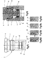
- a cartridge valve 2 is provided as the screw-in part that forms part of the connecting device, which can be screwed into a receiving part in the form of a valve block 4 that forms another part of the connecting device.
- the invention can be used equally with advantage in the case of screw-in and receiving parts of other types in which the accumulation of soiling in the course of the screwing-in process is disruptive.
- the support rings 14 and 16 can preferably consist of a PTFE material.
- the installation space 18 In his in Fig. 2 overhead In the input area, the installation space 18 has an internal thread 20 as a nut thread. Since only the outer contour of the cartridge valve 2 is shown in the drawings, the fluid passages customary in cartridge valves 2 between the interior of the valve body 5 and the installation space 18 in the valve block 4 are not visible, as are the fluid connections within the valve block 4, which open into the installation space 18.
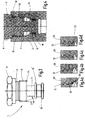
- the in Figures 1 to 2d The first embodiment shown has the cartridge valve 2 on the first thread 22 ( Figures 2a and 2d ) has a chamfered chamfer 24 which is not chamfered at 45 °, as is usual with standard external threads, but, see Fig. 1 , is chamfered at an angle of 30 °.
- the chamfer with a reduced angle leads to a reduction in the size of the contact surface of the first thread turn 22 on the flanks of the internal thread 20 , as in Fig. 2a designated by an arrow 26, which also reduces the occurrence of soiling.
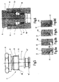
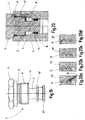
- the Figures 3 to 4d illustrate a second embodiment, in which, in contrast to the first example, the angle of the chamfered chamfer 24 on the first thread turn 22 of the external thread 12 from 30 ° to 20 ° (see FIG. Fig. 3 ) is further reduced.
- the one with arrow 26 in Figure 4a The designated contact area is thereby further reduced in the direction of a line contact, with a correspondingly further reduced risk of contamination.
- the other components of the screw-in part (cartridge valve 2) and of the receiving part (valve block 4) remain unchanged compared to the first example. Since the exemplary embodiments to be described below also differ only with regard to the changed contouring on External thread 12 differ from what has been described above, the description of these exemplary embodiments is limited to the respective contour deviations.
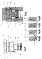
- the Figures 5 to 6d illustrate a third embodiment. This differs from the two first exemplary embodiments in that the first thread turn 22 is not chamfered with a flat chamfer 24, but rather, as indicated by arrow 28 in FIG Fig. 5 indicated, has a rounded portion. Due to the radius cut, the size of the contact area indicated by arrow 26 approaches a line contact, so that the formation of dirt / particles is reduced.
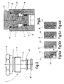
- the first thread turn 22 is turned down to the core diameter in such a way that, starting from the thread root, the first thread turn 22 is turned over with a spiral of the same pitch widening at an angle of 10 °.
- the Figures 9 to 10d show a fifth embodiment.
- the first thread turn 22 has a longitudinal slot 30 running in the axial direction in the area of the chamfer 24 which is gripped at an angle of 45 °.
- the engagement of the first thread turn 22 of the external thread 12 in the internal thread 20 becomes gentler, which reduces the occurrence of dirt / particles.
- no contact surface with the nut thread is formed on the first thread turn 22 in the region of the slot 30.
- the Figures 11 to 12d show a sixth embodiment.
- the first thread turn 22 of the external thread 12 is formed with a smaller flank angle than the remaining thread turns.
- the first thread turn 22 therefore remains without a contact surface (arrow 26 from Figure 12a ), so that the first thread 22 does not cause any contamination / particles.
- the first thread turn 22 has a smaller pitch than the further thread turns.
- the first thread turn 22 therefore remains without a contact surface (see arrow 26 from FIG Figure 14a ).
- the first thread turn 22 therefore does not cause any contamination / particles and cannot push them in front of it either.
- the change in contour on the cartridge valve 2 forming the screw-in part is that, starting from the first thread turn 22 and counter to the screwing-in direction, the flank and core diameters of the external thread 12 in a first thread section from an in Fig. 15 Increase the diameter indicated by D1 to a diameter indicated by D2.
- the external thread 12 does not touch the internal thread 20 until the third thread turn and chambers any dirt / particles that may arise.
- no contact surface is formed in the first courses.
- this solution is characterized in that the flank angles of the adjacent thread turns of the external and internal threads are the same and in this respect are not different from one another.
- the in Figures 17 to 18d The ninth embodiment shown is behind the chamfered gate 24, seen in the screwing direction, see FIG. Figure 17a , a cylindrical section 32 is formed, which is followed by an annular groove 34 of reduced diameter, which merges into the cylindrical section 32 via a 45 ° chamfer 35, see FIG. Figure 17a .
- the recessed annular groove 34 is, as in Figure 18a indicated by arrow 36, a chamber is formed, which prevents dirt / particles caused by screwing in from entering the installation space 18.
- the in Figures 19 to 20d The tenth embodiment shown is at least the first thread turn 22, preferably this is the case with the two first threads, provided with an unequal flank angle compared to the other threads of the cartridge valve, the first thread turn 22 preferably having a tangential outlet. This causes the first thread turn 22, since without a contact surface (see arrow 26 in Figure 20a ), no pollution / particles.
- the sealing system consisting of the two support rings 14, 16 and the sealing ring 15 between them are arranged in an annular receiving groove in the guide part 30, the groove base in this regard being delimited outwardly by an annular flange 14 ', 16'.
- the upper support ring 14 can be supported on the annular flange 14 'and the lower support ring 16 on the lower annular flange 16', which in this respect also forms the lower end wall for the guide part 30.
- the aforementioned sealing system is not shown in all figures.
- the sealing system can also be designed differently, for example only have one sealing ring and one support ring or have a central support ring with two sealing rings on the edge.
- the diameter of the sealing system is correspondingly adapted in relation to the inner wall of the receiving part 4 in order to be able to ensure a sealing effect. Furthermore, guidance of the screw-in part 2 during the screwing-in process is ensured in this way via the guide part 30, in particular when the first thread turns engage with one another at the beginning of the screwing-in process at the upper inlet.
- the upper edge of the guide part 30 closes flush with a conical course along the inner wall side of the receiving part 4, specifically at its smallest diameter.
- This wall section which widens conically upwards in the direction of the screw-in part 2, merges into a cylindrical wall part with an enlarged inner diameter in the receiving part 4, to which the internal thread of the receiving part 4 then adjoins upwards.
- an extension 32 which has a correspondingly reduced axial length in diameter such that the guide function of the guide part 30 is implemented at least at the beginning of the screwing-in process for the screw-in part 2.
Landscapes
- Engineering & Computer Science (AREA)
- General Engineering & Computer Science (AREA)
- Mechanical Engineering (AREA)
- Valve Housings (AREA)
Applications Claiming Priority (1)
| Application Number | Priority Date | Filing Date | Title |
|---|---|---|---|
| DE102019001871.0A DE102019001871A1 (de) | 2019-03-16 | 2019-03-16 | Verbindungsvorrichtung |
Publications (1)
| Publication Number | Publication Date |
|---|---|
| EP3712448A1 true EP3712448A1 (fr) | 2020-09-23 |
Family
ID=69844459
Family Applications (1)
| Application Number | Title | Priority Date | Filing Date |
|---|---|---|---|
| EP20162965.6A Pending EP3712448A1 (fr) | 2019-03-16 | 2020-03-13 | Dispositif de raccordement |
Country Status (2)
| Country | Link |
|---|---|
| EP (1) | EP3712448A1 (fr) |
| DE (1) | DE102019001871A1 (fr) |
Citations (9)
| Publication number | Priority date | Publication date | Assignee | Title |
|---|---|---|---|---|
| US3183531A (en) * | 1961-10-04 | 1965-05-18 | G K N Screw & Fasteners Ltd | Method of forming a screw with cutting edges |
| EP0039559A1 (fr) * | 1980-05-02 | 1981-11-11 | Fluid Controls, Inc. | Ensemble limiteur de pression à commande par détendeur pilote |
| US5341833A (en) * | 1992-07-30 | 1994-08-30 | Don Davis | Tire valve cap |
| US6182697B1 (en) * | 1999-07-08 | 2001-02-06 | Eaton Corporation | Rotary directional valve with integral load holding check |
| DE202004010451U1 (de) * | 2004-07-03 | 2005-11-10 | Richard Bergner Verbindungstechnik Gmbh & Co. Kg | Schraubverbindung zweier Teile und Schraube hierfür |
| US20060207656A1 (en) * | 2005-03-15 | 2006-09-21 | Akihiko Takahashi | Air bleeding pipe joint |
| EP2163773A2 (fr) * | 2008-09-16 | 2010-03-17 | Kamax-Werke Rudolf Kellermann GmbH & Co. KG | Vis à centrage automatique |
| DE102014003197A1 (de) * | 2014-03-04 | 2015-09-10 | GM Global Technology Operations LLC (n. d. Ges. d. Staates Delaware) | Finde-Gewinde |
| CN107781245A (zh) * | 2016-08-30 | 2018-03-09 | 马晓伟 | 新型螺纹插装式负载敏感阀 |
Family Cites Families (4)
| Publication number | Priority date | Publication date | Assignee | Title |
|---|---|---|---|---|
| EP0942181B1 (fr) * | 1998-03-11 | 2003-11-05 | Illinois Tool Works Inc. | Elément de fixation fileté empêchant l'engagement de travers |
| DE10023388A1 (de) * | 2000-05-12 | 2001-11-15 | Mannesmann Rexroth Ag | Hydraulisches Gerät |
| DE102004021484B4 (de) * | 2004-04-30 | 2018-11-29 | Böllhoff Verbindungstechnik GmbH | Verfahren zum Herstellen einer Verbindungsanordnung |
| DE102007036733A1 (de) * | 2007-08-03 | 2009-02-05 | Newfrey Llc, Newark | Gewindebolzen und Verfahren zu seiner Herstellung |
-
2019
- 2019-03-16 DE DE102019001871.0A patent/DE102019001871A1/de active Pending
-
2020
- 2020-03-13 EP EP20162965.6A patent/EP3712448A1/fr active Pending
Patent Citations (9)
| Publication number | Priority date | Publication date | Assignee | Title |
|---|---|---|---|---|
| US3183531A (en) * | 1961-10-04 | 1965-05-18 | G K N Screw & Fasteners Ltd | Method of forming a screw with cutting edges |
| EP0039559A1 (fr) * | 1980-05-02 | 1981-11-11 | Fluid Controls, Inc. | Ensemble limiteur de pression à commande par détendeur pilote |
| US5341833A (en) * | 1992-07-30 | 1994-08-30 | Don Davis | Tire valve cap |
| US6182697B1 (en) * | 1999-07-08 | 2001-02-06 | Eaton Corporation | Rotary directional valve with integral load holding check |
| DE202004010451U1 (de) * | 2004-07-03 | 2005-11-10 | Richard Bergner Verbindungstechnik Gmbh & Co. Kg | Schraubverbindung zweier Teile und Schraube hierfür |
| US20060207656A1 (en) * | 2005-03-15 | 2006-09-21 | Akihiko Takahashi | Air bleeding pipe joint |
| EP2163773A2 (fr) * | 2008-09-16 | 2010-03-17 | Kamax-Werke Rudolf Kellermann GmbH & Co. KG | Vis à centrage automatique |
| DE102014003197A1 (de) * | 2014-03-04 | 2015-09-10 | GM Global Technology Operations LLC (n. d. Ges. d. Staates Delaware) | Finde-Gewinde |
| CN107781245A (zh) * | 2016-08-30 | 2018-03-09 | 马晓伟 | 新型螺纹插装式负载敏感阀 |
Also Published As
| Publication number | Publication date |
|---|---|
| DE102019001871A1 (de) | 2020-09-17 |
Similar Documents
| Publication | Publication Date | Title |
|---|---|---|
| DE69012235T2 (de) | Abdichtanordnung für verriegelte dichte Verbindungen. | |
| DE4002494C2 (fr) | ||
| EP3004702B1 (fr) | Combination d'un boîtier et d'une soupape | |
| DE102008042141A1 (de) | Selbstzentrierende Schraube | |
| EP1864736A2 (fr) | Outil de production de filetage doté d'une jonction de bordure | |
| WO2008113462A1 (fr) | Soupape de réglage | |
| DE102014213610A1 (de) | Gewindeeinsatz und diesen enthaltendes Bauteil | |
| DE202014103640U1 (de) | Schraubdom zum Befestigen eines Bauteils | |
| EP3746692B1 (fr) | Tuyau d'eau avec raccord de tuyau | |
| DE9307361U1 (de) | Anschlußvorrichtung für Rohrleitungen mit geschlitztem Klemmring | |
| DE10334050B4 (de) | Vorrichtung zur Befestigung eines Anschlussfittings an einem Gegenstand, insbesondere an einer Wand | |
| DE202014103192U1 (de) | Bohrwerkzeug | |
| EP1382895A1 (fr) | Raccord enfichable de robinetterie sanitaire | |
| EP2143961B1 (fr) | Arrangement d'étancheité d'alésage | |
| DE102019001871A1 (de) | Verbindungsvorrichtung | |
| DE102009049168A1 (de) | Knochenschraube sowie System | |
| EP3244074B1 (fr) | Dispositif de fixation sur un composant | |
| EP4150242B1 (fr) | Collier profilé pour relier deux corps tubulaires | |
| EP1840435B1 (fr) | Raccord pour tuyaux avec anneau de blocage | |
| EP4522552B1 (fr) | Insert de soupape principale pour une soupape de soutirage | |
| DE20302828U1 (de) | Entlüftungsventil | |
| EP3647624A1 (fr) | Actionneur | |
| DE20009766U1 (de) | Ventil | |
| DE2120952A1 (de) | Kegelventil | |
| DE60203727T2 (de) | Vorrichtung zur befestigung eines gerätes zur brechung der akustischen impedanz eines stiftes |
Legal Events
| Date | Code | Title | Description |
|---|---|---|---|
| PUAI | Public reference made under article 153(3) epc to a published international application that has entered the european phase |
Free format text: ORIGINAL CODE: 0009012 |
|
| STAA | Information on the status of an ep patent application or granted ep patent |
Free format text: STATUS: THE APPLICATION HAS BEEN PUBLISHED |
|
| AK | Designated contracting states |
Kind code of ref document: A1 Designated state(s): AL AT BE BG CH CY CZ DE DK EE ES FI FR GB GR HR HU IE IS IT LI LT LU LV MC MK MT NL NO PL PT RO RS SE SI SK SM TR |
|
| AX | Request for extension of the european patent |
Extension state: BA ME |
|
| STAA | Information on the status of an ep patent application or granted ep patent |
Free format text: STATUS: REQUEST FOR EXAMINATION WAS MADE |
|
| 17P | Request for examination filed |
Effective date: 20210323 |
|
| RBV | Designated contracting states (corrected) |
Designated state(s): AL AT BE BG CH CY CZ DE DK EE ES FI FR GB GR HR HU IE IS IT LI LT LU LV MC MK MT NL NO PL PT RO RS SE SI SK SM TR |
|
| STAA | Information on the status of an ep patent application or granted ep patent |
Free format text: STATUS: EXAMINATION IS IN PROGRESS |
|
| 17Q | First examination report despatched |
Effective date: 20230309 |