EP3712477A1 - Vorrichtung, reihenanordnung und verfahren - Google Patents
Vorrichtung, reihenanordnung und verfahren Download PDFInfo
- Publication number
- EP3712477A1 EP3712477A1 EP20162314.7A EP20162314A EP3712477A1 EP 3712477 A1 EP3712477 A1 EP 3712477A1 EP 20162314 A EP20162314 A EP 20162314A EP 3712477 A1 EP3712477 A1 EP 3712477A1
- Authority
- EP
- European Patent Office
- Prior art keywords
- deviation
- value
- valve unit
- designed
- indicator
- Prior art date
- Legal status (The legal status is an assumption and is not a legal conclusion. Google has not performed a legal analysis and makes no representation as to the accuracy of the status listed.)
- Granted
Links
Images


Classifications
-
- F—MECHANICAL ENGINEERING; LIGHTING; HEATING; WEAPONS; BLASTING
- F16—ENGINEERING ELEMENTS AND UNITS; GENERAL MEASURES FOR PRODUCING AND MAINTAINING EFFECTIVE FUNCTIONING OF MACHINES OR INSTALLATIONS; THERMAL INSULATION IN GENERAL
- F16K—VALVES; TAPS; COCKS; ACTUATING-FLOATS; DEVICES FOR VENTING OR AERATING
- F16K37/00—Special means in or on valves or other cut-off apparatus for indicating or recording operation thereof, or for enabling an alarm to be given
- F16K37/0025—Electrical or magnetic means
- F16K37/005—Electrical or magnetic means for measuring fluid parameters
-
- F—MECHANICAL ENGINEERING; LIGHTING; HEATING; WEAPONS; BLASTING
- F16—ENGINEERING ELEMENTS AND UNITS; GENERAL MEASURES FOR PRODUCING AND MAINTAINING EFFECTIVE FUNCTIONING OF MACHINES OR INSTALLATIONS; THERMAL INSULATION IN GENERAL
- F16K—VALVES; TAPS; COCKS; ACTUATING-FLOATS; DEVICES FOR VENTING OR AERATING
- F16K37/00—Special means in or on valves or other cut-off apparatus for indicating or recording operation thereof, or for enabling an alarm to be given
- F16K37/0075—For recording or indicating the functioning of a valve in combination with test equipment
- F16K37/0083—For recording or indicating the functioning of a valve in combination with test equipment by measuring valve parameters
-
- F—MECHANICAL ENGINEERING; LIGHTING; HEATING; WEAPONS; BLASTING
- F15—FLUID-PRESSURE ACTUATORS; HYDRAULICS OR PNEUMATICS IN GENERAL
- F15B—SYSTEMS ACTING BY MEANS OF FLUIDS IN GENERAL; FLUID-PRESSURE ACTUATORS, e.g. SERVOMOTORS; DETAILS OF FLUID-PRESSURE SYSTEMS, NOT OTHERWISE PROVIDED FOR
- F15B13/00—Details of servomotor systems ; Valves for servomotor systems
- F15B13/02—Fluid distribution or supply devices characterised by their adaptation to the control of servomotors
-
- F—MECHANICAL ENGINEERING; LIGHTING; HEATING; WEAPONS; BLASTING
- F15—FLUID-PRESSURE ACTUATORS; HYDRAULICS OR PNEUMATICS IN GENERAL
- F15B—SYSTEMS ACTING BY MEANS OF FLUIDS IN GENERAL; FLUID-PRESSURE ACTUATORS, e.g. SERVOMOTORS; DETAILS OF FLUID-PRESSURE SYSTEMS, NOT OTHERWISE PROVIDED FOR
- F15B5/00—Transducers converting variations of physical quantities, e.g. expressed by variations in positions of members, into fluid-pressure variations or vice versa; Varying fluid pressure as a function of variations of a plurality of fluid pressures or variations of other quantities
- F15B5/006—Transducers converting variations of physical quantities, e.g. expressed by variations in positions of members, into fluid-pressure variations or vice versa; Varying fluid pressure as a function of variations of a plurality of fluid pressures or variations of other quantities with electrical means, e.g. electropneumatic transducer
-
- F—MECHANICAL ENGINEERING; LIGHTING; HEATING; WEAPONS; BLASTING
- F15—FLUID-PRESSURE ACTUATORS; HYDRAULICS OR PNEUMATICS IN GENERAL
- F15B—SYSTEMS ACTING BY MEANS OF FLUIDS IN GENERAL; FLUID-PRESSURE ACTUATORS, e.g. SERVOMOTORS; DETAILS OF FLUID-PRESSURE SYSTEMS, NOT OTHERWISE PROVIDED FOR
- F15B13/00—Details of servomotor systems ; Valves for servomotor systems
- F15B13/02—Fluid distribution or supply devices characterised by their adaptation to the control of servomotors
- F15B13/025—Pressure reducing valves
-
- F—MECHANICAL ENGINEERING; LIGHTING; HEATING; WEAPONS; BLASTING
- F15—FLUID-PRESSURE ACTUATORS; HYDRAULICS OR PNEUMATICS IN GENERAL
- F15B—SYSTEMS ACTING BY MEANS OF FLUIDS IN GENERAL; FLUID-PRESSURE ACTUATORS, e.g. SERVOMOTORS; DETAILS OF FLUID-PRESSURE SYSTEMS, NOT OTHERWISE PROVIDED FOR
- F15B2211/00—Circuits for servomotor systems
- F15B2211/60—Circuit components or control therefor
- F15B2211/63—Electronic controllers
- F15B2211/6303—Electronic controllers using input signals
- F15B2211/6306—Electronic controllers using input signals representing a pressure
- F15B2211/6313—Electronic controllers using input signals representing a pressure the pressure being a load pressure
-
- F—MECHANICAL ENGINEERING; LIGHTING; HEATING; WEAPONS; BLASTING
- F15—FLUID-PRESSURE ACTUATORS; HYDRAULICS OR PNEUMATICS IN GENERAL
- F15B—SYSTEMS ACTING BY MEANS OF FLUIDS IN GENERAL; FLUID-PRESSURE ACTUATORS, e.g. SERVOMOTORS; DETAILS OF FLUID-PRESSURE SYSTEMS, NOT OTHERWISE PROVIDED FOR
- F15B2211/00—Circuits for servomotor systems
- F15B2211/60—Circuit components or control therefor
- F15B2211/665—Methods of control using electronic components
- F15B2211/6656—Closed loop control, i.e. control using feedback
-
- F—MECHANICAL ENGINEERING; LIGHTING; HEATING; WEAPONS; BLASTING
- F15—FLUID-PRESSURE ACTUATORS; HYDRAULICS OR PNEUMATICS IN GENERAL
- F15B—SYSTEMS ACTING BY MEANS OF FLUIDS IN GENERAL; FLUID-PRESSURE ACTUATORS, e.g. SERVOMOTORS; DETAILS OF FLUID-PRESSURE SYSTEMS, NOT OTHERWISE PROVIDED FOR
- F15B2211/00—Circuits for servomotor systems
- F15B2211/80—Other types of control related to particular problems or conditions
- F15B2211/857—Monitoring of fluid pressure systems
-
- F—MECHANICAL ENGINEERING; LIGHTING; HEATING; WEAPONS; BLASTING
- F15—FLUID-PRESSURE ACTUATORS; HYDRAULICS OR PNEUMATICS IN GENERAL
- F15B—SYSTEMS ACTING BY MEANS OF FLUIDS IN GENERAL; FLUID-PRESSURE ACTUATORS, e.g. SERVOMOTORS; DETAILS OF FLUID-PRESSURE SYSTEMS, NOT OTHERWISE PROVIDED FOR
- F15B2211/00—Circuits for servomotor systems
- F15B2211/80—Other types of control related to particular problems or conditions
- F15B2211/885—Control specific to the type of fluid, e.g. specific to magnetorheological fluid
- F15B2211/8855—Compressible fluids, e.g. specific to pneumatics
Definitions
- the invention relates to a device for industrial automation.
- the device comprises a housing and a valve unit which is arranged in the housing and is designed as a pneumatic proportional valve.
- the device is expediently designed as a valve device.
- the device comprises a display device arranged on the housing for displaying status information about the valve unit.
- the device, in particular the valve device is designed in particular to regulate an actual value, for example a pressure, to a predetermined setpoint value.
- Valve devices currently on the market have a display device, for example a 7-segment display or an LED display, with which the current actual value of the pressure is displayed as status information, for example.
- a display device for example a 7-segment display or an LED display
- valve devices are available which graphically display a ratio of the actual value of the pressure to the maximum possible pressure (hereinafter also referred to as maximum pressure) on their display device.
- maximum pressure the EV03 valve from Aventics GmbH is mentioned at this point.
- An object of the invention is to modify the device mentioned at the beginning so that a Inform users in a quick and easy way how well the valve unit is currently working.
- the object is achieved by a device according to claim 1.
- the device is designed to provide a deviation value based on a setpoint value associated with the valve unit and an actual value associated with the valve unit, and to display a deviation indicator on the display device according to the deviation value.
- the user can quickly and easily determine how well the valve unit regulates the actual value to the setpoint. The user can thus quickly and easily find out how well the valve unit is currently working.
- the deviation indicator can also be used to detect malfunctions and / or control characteristics of the valve unit that do not result from the relationship between the actual pressure and the maximum pressure .
- Cases in which the setpoint changes but the actual value is not tracked quickly enough cannot be seen from the aforementioned conventional display of the relationship between the actual value and the maximum value.
- these cases can be recorded quickly and easily by the user using the deviation indicator.
- the invention further relates to a row arrangement comprising a plurality of mechanically and / or fluidically coupled to one another, lined up in a lined-up direction Devices according to an embodiment described above.
- the invention also relates to a method for operating a device described above, comprising the steps of: providing the deviation value on the basis of the setpoint value associated with the valve unit and the actual value associated with the valve unit and displaying, on the display device, the deviation indicator according to the Deviation value.
- the method is expediently developed in accordance with an embodiment of the device described here.
- the x direction and the y direction can also be referred to as the horizontal directions and the z direction as the vertical direction or height direction.
- the reference system for the spatial directions and other spatial information such as "above” or "below” is the device 10 itself. In the case of a device 10 rotated relative to the surroundings, the reference system and the associated spatial information also rotate.
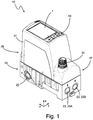
- the Figure 1 shows a device 10.
- the device 10 is exemplified as a valve device with a valve unit.
- the device 10 comprises a display device 1 for displaying status information 2 about the valve unit.
- the status information 2 is exemplified in Figures 2 and 3 shown.
- the device 10 is designed to provide a deviation value based on a setpoint value associated with the valve unit and an actual value associated with the valve information and to display a deviation indicator 3 on the display device 1 according to the deviation value.
- the deviation indicator 3 is exemplified in Figures 2 and 3 shown.
- the device 10 is preferably a field device, in particular a valve device.
- the device 10 is used in particular for use in the field level.
- the device 10 is expediently designed for industrial automation, in particular process automation and / or factory automation.
- the device 10 expediently comprises a valve unit.
- the device 10 preferably comprises a proportional valve, in particular a pneumatic proportional valve.
- the device 10 is designed to use the pneumatic proportional valve to set an actual value to one To regulate setpoint.
- the target value is in particular a target value for a pressure provided by the valve unit.
- the setpoint will also be referred to below as the pressure setpoint.
- the actual value is in particular the pressure provided by the valve unit, for example an output pressure.
- the actual value is also to be referred to as the actual pressure value in the following.
- the valve unit is expediently designed to carry out a regulation in which the valve unit regulates the actual value to the setpoint value.
- valve unit is designed to provide the actual value taking into account a detected sensor value, for example a pressure sensor value.
- the valve unit expediently comprises a sensor, for example a pressure sensor, for detecting the sensor value.
- the sensor with which the sensor value is recorded can also be arranged externally to the valve unit or the device 10.
- the device 10 is expediently dimensioned such that it can be carried manually by a user, in particular with one hand.
- the device 10 can expediently be handled as a unit.
- the device 10 comprises a housing 14, which is in particular the outer housing of the device 10. All components of the device 10 are preferably arranged in or on the housing 14.
- the device 10 expediently comprises one or more fluidic connections.
- the device 10 includes a fluidic supply connection 22 and / or one or more fluidic working connections 23.
- the working connections 23 include, for example, a ventilation connection 23A and / or a ventilation connection 23B.
- a pressurized fluid for example compressed air, is fed to the device 10 via the fluidic supply connection 22.
- the device 10 provides an output pressure according to the predefined setpoint value.
- the device 10 further comprises an electrical interface 24.
- the electrical interface 24 is used in particular to receive an electrical input signal with which, for example, the setpoint is specified.
- an arrangement is provided which comprises the device 10 and a higher-level controller, for example a PLC, memory-programming controller.
- the higher-level controller is communicatively connected to the device 10, in particular via the electrical interface 24.
- the device 10 receives the electrical input signal from the higher-level controller, which specifies the target value, and regulates its output pressure according to the target value.
- the device 10 expediently comprises a processing unit (not shown in the figures).
- the device 10 is designed in particular to provide the deviation value on the basis of the nominal value and the actual value by means of the processing unit.
- the processing unit is designed, for example, as a microcontroller, FPGA and / or ASIC.
- the device 10, in particular the processing unit is expediently designed to calculate the deviation value on the basis of the setpoint value and the actual value.
- the device 10, in particular the Processing unit designed to provide the deviation value on the basis of a difference between the target value and the actual value.
- the deviation value is the difference between the target value and the actual value.
- the device 10, in particular the processing unit, is expediently designed to provide the deviation value on the basis of a maximum value (ie a maximum possible value) for the actual value and / or the setpoint value.
- the device 10 in particular the processing unit, is expediently designed to provide the deviation value as a control quality.
- the setpoint value and the actual value relate to a pressure, in particular the output pressure provided by the valve device.
- the setpoint and the actual value can also relate to another variable, in particular a flow rate, a stroke and / or a force.
- the other variable, in particular the flow rate, the stroke and / or the force, is expediently related to the valve device.
- the device is designed to provide two or more deviation values, each deviation value concerns another size, in particular one of the aforementioned sizes.
- the device is expediently designed to display a plurality of deviation indicators on the display device 1, each deviation indicator expediently being based on a different deviation value, that is, a different variable.
- the x extension is expediently smaller than the y extension and / or smaller than the z extension.
- the device 10 has two longitudinal sides which are oriented perpendicular to the x-direction and which are expediently designed to be essentially planar.
- a further device 10 can expediently be coupled mechanically and / or fluidically on each longitudinal side in order to form a row arrangement 20.
- the device 10 is exemplarily designed as a row module.
- the fluidic supply connection 22 is expediently arranged on a longitudinal side.
- the device 10 also has two end faces oriented perpendicular to the y direction.
- the two fluidic work connections 23 are arranged on one end face.
- the device 10 comprises a lower section 25, on which an upper section 26 and a shoulder section 27 are expediently arranged next to one another in the y-direction.
- the fluidic connections 22, 23 are arranged on the lower section 25, the electrical interface 24 on the shoulder section 27 and / or the display device 1 on the upper section 25.
- the device 10 expediently comprises an operating device 19, which preferably comprises one or more buttons.
- the operating device 19 comprises three buttons.
- the operating device 19 is arranged by way of example on the upper section 26, in particular on the top of the device 10, preferably next to the display device 1.
- the operating device 19 is arranged in the y-direction next to the display device 1 as an example.
- the valve unit is preferably arranged in the housing 14.
- the display device 1 is expediently arranged on the outside of the housing 14.
- the display device 1 is arranged on the top of the housing 14, in particular the top of the upper section 26.
- the upper side is aligned normal to the z-direction, for example.
- the display device 1 is, in particular, a graphic display which can preferably display numerical elements and / or graphic elements.
- Numerical elements are intended to refer to characters, in particular numerals, with which a number is represented.
- a graphic element (for example the deviation graphic element) is intended to mean an element displayed by the display device 1 that does not contain and / or form a number, a digit and / or a letter. In particular, a graphic element does not contain a number element and / or number sign.
- a graphic element is in particular a non-numerical element.
- a graphic element is preferably without digits.
- a graphic element is expediently a geometric figure, for example a rectangle.
- the display device 1 expediently has a large number of pixels, for example more than 100 pixels.
- the Display device 1 is expediently designed to display the numerical elements and / or graphic elements, in particular the deviation graphic element 5, by controlling the pixels.
- Each number element and / or each graphic element, in particular the deviation graphic element 5, is expediently represented by a plurality of pixels, in particular at least 10 pixels.
- the display device 1 lies, for example, in an x-y plane.
- the display device 1 is expediently designed to be rectangular, the y extension of the display device 1 preferably being greater than the x extension.
- the display device 1 is expediently designed to display various displays.
- An ad can also be referred to as a page or a view.
- the display device 1 is expediently designed to display a standard view or main view.
- the standard view or main view is in particular that view which is displayed as standard during operation, in particular after the device 10 has been switched on and / or without actuation of the operating device 19.
- the standard view or main view preferably includes the deviation indicator 3.
- Status information 2 is displayed on the display device.
- the status information 2 comprises a representation of the setpoint value and / or the actual value.
- the target value is exemplarily represented as a target value numerical element 9 - that is to say by means of characters, in particular numerals.
- the actual value is represented by way of example as an actual value numerical element 11 - that is to say by means of characters, in particular numerals.
- the setpoint and / or the actual value can also be displayed as a graphic element.
- the status information 2 also includes the deviation indicator 3, which is explained in more detail below.
- the device 10 is expediently designed to keep the displayed status information 2 - i.e. the displayed target value, actual value and / or the deviation indicator 3 - up-to-date according to the underlying target value, actual value and / or deviation value, in particular to update it continuously, expediently to display it in real time.
- the displayed status information in particular the displayed setpoint value, actual value and / or deviation indicator 3, expediently always corresponds to the current value of the underlying (in particular physical) variable.
- the deviation indicator 3 in particular designed as a graph, shows a deviation in a pressure.
- the deviation indicator 3 can furthermore show a deviation from another physical one Display controlled variable, e.g. a flow rate, a stroke and / or a force.
- the deviation indicator 3 optionally shows a deviation of a controlled variable that is integrated into an internal control loop of the valve unit via a sensor, for example a force sensor.
- the deviation indicator 3 comprises, for example, a deviation graphic element 5.
- the size, color, shape and / or position of the deviation graphic element 5 depends on the deviation value.
- the device 10 is thus designed to display the deviation graphic element 5, in particular its size, color, shape and / or position as a function of the deviation value.
- the deviation graphic element 5 in particular does not include any characters, in particular no numerals.
- the device 10 is expediently designed to map the deviation value onto the size, color, shape and / or position of the deviation graphic element 5.
- the device 10 is designed to map a plurality (in particular at least five or at least ten) different values of the deviation value onto a plurality (in particular at least five or at least ten) different sizes, colors, shapes and / or positions of the deviation graphic element 5.
- the device 10 is designed, in particular, to map the deviation value continuously to the size, color, shape and / or position of the deviation graphic element 5.
- the device 10 is designed in particular to display a plurality (in particular at least five or at least ten) of different values of the deviation value in a visually distinguishable manner by means of the deviation graphic element 5, in particular by means of the size, color, shape and / or position of the deviation graphic element 5 .
- the deviation indicator 3 comprises a deviation numerical element 4 - that is to say one or more characters, in particular numerals.
- the numerical deviation element 4 is a number which is equal to the deviation value provided by the processing unit, in particular equal to the current deviation value.
- the deviation indicator 3 is designed in particular as a deviation graph or deviation diagram.
- the deviation indicator 3 is exemplified as a bar graph.
- the deviation indicator can also be referred to here as a bar chart.
- the deviation indicator 3 comprises a bar 6, the size of which, in particular its x-extent, depends on the deviation value.
- the bar 6 is an exemplary embodiment of the above-mentioned deviation graphic element 5.
- the device 10 is designed to adapt the length, in particular the x extension, of the bar 6 according to the deviation value, in particular in real time.
- the deviation value is expediently mapped onto this length of the bar 6, so that this length of the bar 6 is proportional to the deviation value.
- the device 10 is designed in particular to map the deviation value to the length of the bar 6, in particular continuously in value.
- a first end of the bar 6 (located in the x direction) is fixed - that is, constantly at the same position - shown as an example in a central x area of the display device 1, and the position of a second end of the bar 6 is determined according to the deviation value adjusted, especially in real time.
- the bar 6 expediently extends depending on the sign of the Deviation value to the right or to the left.
- the second end of the bar 6 is shown in the case of a negative deviation value to the left of the first end of the bar 6, so that the bar 6 extends to the left.
- the second end of the bar 6 is shown to the right of the first end of the bar 6, so that the bar 6 extends to the right.
- the length of the bar 6 is expediently constantly updated, so that the bar 6 is displayed as an animated graphic element when the deviation value changes.
- the deviation indicator 3 also includes a target value graphic element 16, which is embodied as a bar, in particular a central bar.
- the setpoint graphic element 16 is expediently a stationary reference element for the deviation graphic element.
- the target value graphic element 16 is expediently constant in its position and / or size.
- the target value graphic element 16 shows in particular that position in which the actual value is equal to the target value, that is to say in particular the position in which the deviation value is equal to zero. The deviation between the actual value and the target value can be read off quickly and easily from the distance between the second end of the bar 6 and the target value graphic element 16.
- the deviation graphic element 5, in particular the bar 6, expediently has an extent, in particular an x-extent of zero, and is accordingly not displayed.
- the deviation indicator 3 expediently further comprises an area display graphic element 17, which is exemplarily designed as a line extending in the x direction.
- the area display graphic element 17 shows, by way of example, the maximum area within which the deviation graphic element 5, in particular the bar 6, can be located, in particular in the case of a maximum deviation value (in terms of amount).
- the status information 2 is oriented in such a way that the number elements can be read from left to right in the x direction.
- the various elements of the status information 2 are arranged one below the other in the y direction.
- the actual value numerical element 11 is arranged in the upper y area of the display device 1 and the desired value numerical element 9 is arranged below it in the y direction.
- the deviation indicator 3 is arranged by way of example in the y-direction below the setpoint number element 9.
- the deviation indicator 3 comprises the deviation numerical element 4 under which the deviation graphic element 5 and optionally the target value graphic element 16 are arranged in the y direction.
- the area display graphic element 17 is optionally arranged in the y-direction under the deviation graphic element 5.
- the second exemplary embodiment is expediently designed like the first exemplary embodiment explained above, with the exception of the differences explained below.
- the deviation graphic element 5 is exemplarily designed as a marker 7, the position of which depends on the deviation value.
- the marker 7 has the shape of a triangle, in particular a triangle standing on a corner. Alternatively, the marker 7 can also have a different shape, for example the shape of a rectangle or a circle.
- the x position of the marker 7 expediently depends on the deviation value. If the actual value is equal to the nominal value, the marker 7 is displayed with the same x-position as the nominal value graphic element 16. If the actual value is less than the nominal value, the marker 7 is shown by way of example to the left of the nominal value graphic element 16. If the actual value is greater than the target value, the marker 7 is displayed to the right of the target value graphic element 16 as an example.
- the deviation indicator 3 comprises, for example, a scale 15.
- the deviation indicator 3 also comprises the target value graphic element 16, by means of which the target value is graphically represented as a stationary reference.
- the setpoint graphic element is designed as a central bar on scale 15, for example.
- the deviation indicator 3 expediently comprises one or more limit values for the deviation value, which are represented as limit value numerical elements and / or as limit value graphic elements 18.
- the limit values are shown graphically as limit value graphic elements 18.
- the limit value graphic elements 18 are exemplarily designed as side bars which they are expediently located to the left and right of the central bar.
- the limit value graphic elements are exemplary 18 each represents a deviation of 1% of the maximum pressure from the setpoint.
- the marker 7 is expediently displayed on or near the corresponding limit value graphic element 18.
- the marker 7 is expediently not moved beyond the limit value graphic elements 18.
- the marker 7 can also be referred to as a pen.
- the marker 7 or another part of the scale 15 expediently changes color, for example to red, in particular when the deviation value is equal to a limit value and / or lies outside the range defined by the limit values.
- the deviation indicator 3 optionally includes a scale division 21.
- the device 10 is expediently designed to adapt the scale division 21, in particular dynamically.
- the scale division 21 comprises, for example, a plurality of scale bars, which in particular each extend in the y-direction.
- the device 10 optionally has a setting option, for example by means of the operating device 19, in order to be able to set the limit values for the deviation value individually.
- the setting is possible in particular manually using a menu.
- the Limit values are established during the manufacture of the device 10, in particular in accordance with a customer specification.
- the device optionally has a data interface, in particular an IO-Link interface and / or a Bluetooth interface, via which the limit values can be changed in particular remotely, expediently during operation and / or during maintenance.
- the data interface can be provided in addition to the electrical interface 24. Alternatively, the data interface can also be provided by the electrical interface 24.
- the Figure 4 shows a row arrangement 20 which comprises a plurality of devices 10 which are lined up in a row direction x and mechanically and / or fluidically coupled to one another.
- the devices 10 each lie against one another with their long sides.
- the devices 10 together form a substantially cuboid body.
- the outer contour of an xy section through the row arrangement 20 is, for example, rectangular.
- the display devices 1 lie next to one another in the x direction.
- several, in particular all, devices 10 display a respective deviation indicator 3. The user can see at a glance how well the controls provided by the multiple devices 10 are working.
- the device 10 comprises in particular a pneumatic proportional valve as a valve unit.
- the device 10 is designed to use the proportional valve to regulate an actual value of a pressure to a setpoint value, which is expediently is specified by a user.
- the device 10 is expediently designed to receive an electronic input signal, which specifies the setpoint value, and to convert the electronic input signal into a corresponding pressure as an actual value with the pneumatic proportional valve.
- the device 10 is expediently designed to graphically display the current accuracy, in particular the current deviation between the target value and the actual value, by means of the display device 1.
- the device 10 is designed not to show the relationship between the actual value of the pressure and the maximum possible pressure, in particular not to show it graphically.
- the device 10 is designed to display the deviation indicator 3 on the display device 1.
- the device 10 is designed in particular to provide the deviation indicator 3 as a graph, in particular as a deviation graph.
- the deviation graph can also be referred to as a derivative graph.
- the graph shows the deviation of the current actual value from the desired target value.
- the graph expediently shows the control quality of the pressure control.
- the device 10 is designed in particular to display the deviation indicator 3 when the device 10 is put into operation and / or during normal operation.
- the deviation indicator 3 - in particular the information about the control quality of a proportional valve within the controlled system - can be more helpful than the conventional graphic display of a current pressure in relation to the maximum possible pressure.
- changes in the setpoint result in brief phases in which the actual value provided by the valve unit is outside the desired accuracy.
- Faults on the output side e.g. mass changes, etc.
- the actual pressure usually only changes slightly, so that the (conventional) display of the actual pressure relative to the maximum pressure does not make these phenomena visible.
- the deviation indicator 3 By providing the deviation indicator 3, however, these cases can be recognized quickly and easily by the user so that he can initiate appropriate countermeasures if necessary.
Landscapes
- Engineering & Computer Science (AREA)
- General Engineering & Computer Science (AREA)
- Mechanical Engineering (AREA)
- Physics & Mathematics (AREA)
- Fluid Mechanics (AREA)
- Indication Of The Valve Opening Or Closing Status (AREA)
Abstract
Description
- Die Erfindung betrifft eine Vorrichtung für die Industrieautomatisierung. Die Vorrichtung umfasst ein Gehäuse und eine in dem Gehäuse angeordnete Ventileinheit, die als pneumatisches Proportionalventil ausgebildet ist. Die Vorrichtung ist zweckmäßigerweise als Ventilvorrichtung ausgebildet. Die Vorrichtung umfasst eine am Gehäuse angeordnete Anzeigeeinrichtung zur Anzeige einer Zustandsinformation über die Ventileinheit. Die Vorrichtung, insbesondere die Ventilvorrichtung, ist insbesondere ausgebildet, einen Istwert, beispielsweise eines Drucks, auf einen vorgegebenen Sollwert zu regeln.
- Aktuell auf dem Markt befindliche Ventilvorrichtungen verfügen über eine Anzeigeeinrichtung, beispielsweise eine 7-Segment-Anzeige oder eine LED-Anzeige, mit der als Zustandsinformation beispielsweise der momentane Istwert des Drucks angezeigt wird. Es sind insbesondere Ventilvorrichtungen erhältlich, die auf ihrer Anzeigeeinrichtung ein Verhältnis des Istwerts des Drucks zum maximal möglichen Druck (nachfolgend auch als Maximaldruck bezeichnet) grafisch darstellen. Rein exemplarisch sei an dieser Stelle das Ventil EV03 der Aventics GmbH genannt.
- Eine Aufgabe der Erfindung besteht darin, die eingangs genannte Vorrichtung so zu modifizieren, dass sich ein Benutzer in schneller und einfacher Weise darüber informieren kann, wie gut die Ventileinheit aktuell funktioniert.
- Die Aufgabe wird gelöst durch eine Vorrichtung gemäß Anspruch 1. Die Vorrichtung ist ausgebildet, auf Basis eines mit der Ventileinheit im Zusammenhang stehenden Sollwerts und eines mit der Ventileinheit im Zusammenhang stehenden Istwerts einen Abweichungswert bereitzustellen und gemäß dem Abweichungswert einen Abweichungsindikator auf der Anzeigeeinrichtung anzuzeigen.
- Anhand des angezeigten Abweichungsindikators kann der Benutzer schnell und einfach erfassen, wie gut die Ventileinheit den Istwert auf den Sollwert regelt. Der Benutzer kann sich somit in schneller und einfacher Weise darüber informieren, wie gut die Ventileinheit aktuell funktioniert.
- Gegenüber den vorstehend erwähnten Ventilvorrichtungen, die ein Verhältnis zwischen Ist-Druck und Maximaldruck anzeigen, wird insbesondere der Vorteil erzielt, dass über den Abweichungsindikator auch Störungen und/oder Regelcharakteristiken der Ventileinheit feststellbar sind, die aus dem Verhältnis aus Ist-Druck und Maximaldruck nicht hervorgehen. So sind z.B. Fälle, in denen sich der Sollwert ändert aber der Istwert nicht schnell genug nachgeführt wird, über die erwähnte konventionelle Anzeige des Verhältnisses aus Istwert und Maximalwert nicht ersichtlich. Mittels des Abweichungsindikators können diese Fälle jedoch schnell und einfach vom Benutzer erfasst werden.
- Die Erfindung betrifft ferner eine Reihenanordnung, umfassend eine Mehrzahl von in einer Aufreihungsrichtung aufgereihten, mechanisch und/oder fluidisch miteinander gekoppelten Vorrichtungen gemäß einer vorstehend beschriebenen Ausgestaltung.
- Die Erfindung betrifft ferner ein Verfahren zum Betrieb einer vorstehend beschriebenen Vorrichtung, umfassend die Schritte: Bereitstellen des Abweichungswerts auf Basis des mit der Ventileinheit im Zusammenhang stehenden Sollwerts und des mit der Ventileinheit im Zusammenhang stehenden Istwerts und Anzeigen, auf der Anzeigeeinrichtung, des Abweichungsindikators gemäß dem Abweichungswert. Das Verfahren ist zweckmäßigerweise gemäß einer hier beschriebenen Ausgestaltung der Vorrichtung weitergebildet.
- Nachstehend werden exemplarische Ausführungsformen unter Bezugnahme auf die Figuren erläutert. Dabei zeigt
- Figur 1
- eine perspektivische Ansicht einer exemplarischen Vorrichtung,
- Figur 2
- eine erste exemplarische Ausführung einer Anzeige mit einem Abweichungsindikator,
- Figur 3
- eine zweite exemplarische Ausführung einer Anzeige mit einem Abweichungsindikator und
- Figur 4
- eine Ansicht von oben auf eine Reihenanordnung.
- Bei der nachfolgenden Erläuterung wird auf die orthogonal zueinander ausgerichteten Raumrichtungen "x-Richtung", "y-Richtung" und "z-Richtung" Bezug genommen. Die x-Richtung und die y-Richtung können auch als Horizontalrichtungen und die z-Richtung als Vertikalrichtung oder Höhenrichtung bezeichnet werden. Das Bezugssystem für die Raumrichtungen und andere räumliche Angaben wie "oben" oder "unten" ist die Vorrichtung 10 selbst. Bei einer relativ zur Umgebung gedrehten Vorrichtung 10 dreht sich das Bezugssystem und die damit zusammenhängenden räumlichen Angaben mit.
- Die
Figur 1 zeigt eine Vorrichtung 10. Die Vorrichtung 10 ist exemplarisch als Ventilvorrichtung mit einer Ventileinheit ausgebildet. Die Vorrichtung 10 umfasst eine Anzeigeeinrichtung 1 zur Anzeige einer Zustandsinformation 2 über die Ventileinheit. Die Zustandsinformation 2 ist exemplarisch in denFiguren 2 und3 gezeigt. - Die Vorrichtung 10 ist ausgebildet, auf Basis eines mit der Ventileinheit im Zusammenhang stehenden Sollwerts und eines mit der Ventilinformation im Zusammenhang stehenden Istwerts einen Abweichungswert bereitzustellen und gemäß dem Abweichungswert einen Abweichungsindikator 3 auf der Anzeigeeinrichtung 1 anzuzeigen. Der Abweichungsindikator 3 ist exemplarisch in den
Figuren 2 und3 gezeigt. - Nachfolgend werden weitere exemplarisch Details erläutert.
- Bei der Vorrichtung 10 handelt es sich vorzugsweise um ein Feldgerät, insbesondere um eine Ventileinrichtung. Die Vorrichtung 10 dient insbesondere für den Einsatz in der Feldebene. Zweckmäßigerweise ist die Vorrichtung 10 für die Industrieautomatisierung, insbesondere die Prozessautomatisierung und/oder die Fabrikautomatisierung ausgebildet.
- Die Vorrichtung 10 umfasst zweckmäßigerweise eine Ventileinheit. Vorzugsweise umfasst die Vorrichtung 10 ein Proportionalventil, insbesondere ein pneumatisches Proportionalventil. Die Vorrichtung 10 ist ausgebildet, mit dem pneumatischen Proportionalventil einen Istwert auf einen Sollwert zu regeln. Bei dem Sollwert handelt es sich insbesondere um einen Sollwert für einen von der Ventileinheit bereitgestellten Druck. Der Sollwert soll nachstehend auch als Druck-Sollwert bezeichnet werden. Bei dem Istwert handelt es sich insbesondere um den von der Ventileinheit bereitgestellt Druck, beispielsweise einen Ausgangsdruck. Der Istwert soll nachstehend auch als Druck-Istwert bezeichnet werden. Die Ventileinheit ist zweckmäßigerweise ausgebildet, eine Regelung durchzuführen, bei der die Ventileinheit den Istwert auf den Sollwert regelt. Exemplarisch ist die Ventileinheit ausgebildet, den Istwert unter Berücksichtigung eines erfassten Sensorwerts, beispielsweise eines Drucksensorwerts, bereitzustellen. Zweckmäßigerweise umfasst die Ventileinheit einen Sensor, beispielsweise einen Drucksensor, zur Erfassung des Sensorwerts. Alternativ dazu kann der Sensor, mit dem der Sensorwert erfasst wird, auch extern zu der Ventileinheit oder der Vorrichtung 10 angeordnet sein.
- Die Vorrichtung 10 ist zweckmäßigerweise derart dimensioniert, dass sie von einem Benutzer manuell getragen werden kann, insbesondere mit einer Hand. Zweckmäßigerweise ist die Vorrichtung 10 als Einheit handhabbar. Exemplarisch umfasst die Vorrichtung 10 ein Gehäuse 14, bei dem es sich insbesondere um das Außengehäuse der Vorrichtung 10 handelt. Vorzugsweise sind sämtliche Bestandteile der Vorrichtung 10 in oder an dem Gehäuse 14 angeordnet.
- Die Vorrichtung 10 umfasst zweckmäßigerweise einen oder mehrere fluidische Anschlüsse. Exemplarisch umfasst die Vorrichtung 10 einen fluidischen Versorgungsanschluss 22 und/oder einen oder mehrere fluidische Arbeitsanschlüsse 23. Die Arbeitsanschlüsse 23 umfassen exemplarisch einen Entlüftungsanschluss 23A und/oder einen Belüftungsanschluss 23B. Über den fluidischen Versorgungsanschluss 22 wird der Vorrichtung 10 ein Druckfluid, beispielsweise Druckluft, zugeführt. An einem fluidischen Arbeitsanschluss 23, insbesondere dem Belüftungsanschluss 23B, stellt die Vorrichtung 10 einen Ausgangsdruck gemäß dem vorgegebenen Sollwert bereit.
- Die Vorrichtung 10 umfasst ferner eine elektrische Schnittstelle 24. Die elektrische Schnittstelle 24 dient insbesondere dazu, ein elektrisches Eingangssignal zu empfangen, mit dem beispielsweise der Sollwert vorgegeben wird. Gemäß einer exemplarischen (in den Figuren nicht gezeigten) Ausgestaltung wird eine Anordnung bereitgestellt, die die Vorrichtung 10 und eine übergeordnete Steuerung, beispielsweise eine SPS, speicherprogrammiere Steuerung, umfasst. Die übergeordnete Steuerung ist mit der Vorrichtung 10 kommunikativ verbunden, insbesondere über die elektrische Schnittstelle 24. Die Vorrichtung 10 empfängt von der übergeordneten Steuerung das elektrische Eingangssignal, das den Sollwert vorgibt, und regelt ihren Ausgangsdruck gemäß dem Sollwert.
- Die Vorrichtung 10 umfasst zweckmäßigerweise eine (in den Figuren nicht gezeigte) Verarbeitungseinheit. Die Vorrichtung 10 ist insbesondere ausgebildet, mittels der Verarbeitungseinheit den Abweichungswert auf Basis des Sollwerts und des Istwerts bereitzustellen. Die Verarbeitungseinheit ist beispielsweise als Mikrocontroller, FPGA und/oder ASIC ausgeführt.
- Zweckmäßigerweise ist die Vorrichtung 10, insbesondere die Verarbeitungseinheit, ausgebildet, den Abweichungswert auf Basis des Sollwerts und des Istwerts zu berechnen. Beispielsweise ist die Vorrichtung 10, insbesondere die Verarbeitungseinheit, ausgebildet, den Abweichungswert auf Basis einer Differenz zwischen dem Sollwert und dem Istwert bereitzustellen. Gemäß einer möglichen Ausgestaltung ist der Abweichungswert die Differenz zwischen dem Sollwert und dem Istwert.
- Zweckmäßigerweise ist die Vorrichtung 10, insbesondere die Verarbeitungseinheit, ausgebildet, den Abweichungswert auf Basis eines Maximalwerts (also eines maximal möglichen Werts) für den Istwert und/oder den Sollwert bereitzustellen. Beispielsweise ist die Vorrichtung 10 ausgebildet, den Abweichungswert als das Verhältnis der vorgenannten Differenz zwischen Sollwert und Istwert zu dem Maximalwert bereitzustellen, insbesondere zu berechnen; also beispielsweise als:

- Zweckmäßigerweise ist die Vorrichtung 10, insbesondere die Verarbeitungseinheit, ausgebildet, den Abweichungswert als Regelgüte bereitzustellen.
- Exemplarisch betreffen der Sollwert und der Istwert einen Druck, insbesondere den von der Ventilvorrichtung bereitgestellten Ausgangsdruck. Alternativ oder zusätzlich dazu können der Sollwert und der Istwert auch eine andere Größe, insbesondere einen Durchfluss, einen Hub und/oder eine Kraft betreffen. Zweckmäßigerweise steht die andere Größe, insbesondere der Durchfluss, der Hub und/oder die Kraft im Zusammenhang mit der Ventilvorrichtung.
- Gemäß einer möglichen (in den Figuren nicht gezeigten) Ausgestaltung ist die Vorrichtung ausgebildet, zwei oder mehr Abweichungswerte bereitzustellen, wobei jeder Abweichungswert eine andere Größe, insbesondere eine aus den vorgenannten Größen, betrifft. Gemäß dieser Ausgestaltung ist die Vorrichtung zweckmäßigerweise ausgebildet, auf der Anzeigeeinrichtung 1 mehrere Abweichungsindikatoren anzuzeigen, wobei zweckmäßigerweise jeder Abweichungsindikator auf einem anderen Abweichungswert, also einer anderen Größe, basiert.
- Die Vorrichtung 10, insbesondere das Gehäuse 14, weist zweckmäßigerweise eine quaderförmige und/oder scheibenförmige Grundgestalt auf. Die x-Erstreckung ist zweckmäßigerweise kleiner als die y-Erstreckung und/oder kleiner als die z-Erstreckung. Die Vorrichtung 10 verfügt über zwei senkrecht zur x-Richtung ausgerichtete Längsseiten, die zweckmäßigerweise im Wesentlichen planar ausgeführt sind. Zweckmäßigerweise kann an jeder Längsseite eine weitere Vorrichtung 10 mechanisch und/oder fluidisch angekoppelt werden, um so eine Reihenanordnung 20 zu bilden. Die Vorrichtung 10 ist exemplarisch als Reihenmodul ausgebildet.
- Zweckmäßigerweise ist der fluidische Versorgungsanschluss 22 an einer Längsseite angeordnet. Die Vorrichtung 10 verfügt ferner über zwei senkrecht zur y-Richtung ausgerichtete Stirnseiten. Exemplarisch sind die beiden fluidische Arbeitsanschlüsse 23 an einer Stirnseite angeordnet.
- Die Vorrichtung 10 umfasst einen unteren Abschnitt 25, auf dem zweckmäßigerweise in y-Richtung nebeneinander ein oberer Abschnitt 26 und ein Schulterabschnitt 27 angeordnet sind. Exemplarisch sind an dem unteren Abschnitt 25 die fluidischen Anschlüsse 22, 23, an dem Schulterabschnitt 27 die elektrische Schnittstelle 24 und/oder an dem oberen Abschnitt 25 die Anzeigeeinrichtung 1 angeordnet.
- Die Vorrichtung 10 umfasst zweckmäßigerweise eine Bedieneinrichtung 19, die vorzugsweise eine oder mehrere Tasten umfasst. Exemplarisch umfasst die Bedieneinrichtung 19 drei Tasten. Die Bedieneinrichtung 19 ist exemplarisch an dem oberen Abschnitt 26 angeordnet, insbesondere auf der Oberseite der Vorrichtung 10, vorzugsweise neben der Anzeigeeinrichtung 1. Exemplarisch ist die Bedieneinrichtung 19 in y-Richtung neben der Anzeigeeinrichtung 1 angeordnet.
- Die Ventileinheit ist vorzugsweise in dem Gehäuse 14 angeordnet. Die Anzeigeeinrichtung 1 ist zweckmäßigerweise außen an dem Gehäuse 14 angeordnet. Exemplarisch ist die Anzeigeeinrichtung 1 an der Oberseite des Gehäuses 14, insbesondere der Oberseite des oberen Abschnitts 26, angeordnet. Die Oberseite ist exemplarisch normal zur z-Richtung ausgerichtet.
- Bei der Anzeigeeinrichtung 1 handelt es sich insbesondere um eine grafische Anzeige, die vorzugsweise Zahlenelemente und/oder Grafikelemente darstellen kann. Als Zahlenelemente sollen Schriftzeichen, insbesondere Zahlzeichen bezeichnet werden, mit denen eine Zahl dargestellt wird. Mit einem Grafikelement (beispielsweise dem Abweichungs-Grafikelement) soll ein von der Anzeigeeinrichtung 1 angezeigtes Element gemeint sein, das keine Zahl, keine Ziffer und/oder kein Buchstabe ist, enthält und/oder bildet. Ein Grafikelement enthält insbesondere kein Zahlenelement und/oder Zahlzeichen. Ein Grafikelement ist insbesondere ein nicht-numerisches Element. Vorzugsweise ist ein Grafikelement ziffernlos. Zweckmäßigerweise ist ein Grafikelement eine geometrische Figur, beispielsweise ein Rechteck.
- Die Anzeigeeinrichtung 1 verfügt zweckmäßigerweise über eine Vielzahl an Pixeln, beispielsweise mehr als 100 Pixel. Die Anzeigeeinrichtung 1 ist zweckmäßigerweise ausgebildet, die Zahlenelemente und/oder Grafikelemente, insbesondere das Abweichungs-Grafikelement 5, durch Ansteuerung der Pixel darzustellen. Zweckmäßigerweise wird jedes Zahlenelement und/oder jedes Grafikelement, insbesondere das Abweichungs-Grafikelement 5, jeweils durch eine Vielzahl von Pixeln, insbesondere wenigstens 10 Pixeln, dargestellt.
- Die Anzeigeeinrichtung 1 liegt exemplarisch in einer x-y-Ebene. Zweckmäßigerweise ist die Anzeigeeinrichtung 1 rechteckig ausgeführt, wobei die y-Erstreckung der Anzeigeeinrichtung 1 vorzugsweise größer ist als die x-Erstreckung.
- Die Anzeigeeinrichtung 1 ist zweckmäßigerweise ausgebildet, verschiedene Anzeigen anzuzeigen. Eine Anzeige kann auch als Seite oder Ansicht bezeichnet werden. Exemplarisch kann über die Bedieneinrichtung 19 zwischen verschiedenen Anzeigen gewechselt werden.
- Zweckmäßigerweise ist die Anzeigeeinrichtung 1 ausgebildet, eine Standardansicht oder Hauptansicht anzuzeigen. Die Standardansicht oder Hauptansicht ist insbesondere diejenige Ansicht, die im Betrieb standardmäßig angezeigt wird, insbesondere nach dem Einschalten der Vorrichtung 10 und/oder ohne Betätigung der Bedieneinrichtung 19. Vorzugsweise umfasst die Standardansicht oder Hauptansicht den Abweichungsindikator 3.
- Nachstehend soll unter Bezugnahme auf die
Figur 2 auf eine erste exemplarische Ausgestaltung einer Ansicht, insbesondere der Hauptansicht, der Anzeigeeinrichtung 1 eingegangen werden. - Auf der Anzeigeeinrichtung wird eine Zustandsinformation 2 angezeigt. Exemplarisch umfasst die Zustandsinformation 2 eine Darstellung des Sollwerts und/oder des Istwerts. Der Sollwert wird exemplarisch als Sollwert-Zahlenelement 9 - also mittels Schriftzeichen, insbesondere Zahlzeichen - dargestellt. Der Istwert wird exemplarisch als Istwert-Zahlenelement 11 - also mittels Schriftzeichen, insbesondere Zahlzeichen - dargestellt. Alternativ oder zusätzlich dazu können der Sollwert und/oder der Istwert auch als Grafikelement dargestellt werden.
- Die Zustandsinformation 2 umfasst ferner den nachstehend noch näher erläuterten Abweichungsindikator 3.
- Die Vorrichtung 10 ist zweckmäßigerweise ausgebildet, die angezeigte Zustandsinformation 2 - also den angezeigten Sollwert, Istwert und/oder den Abweichungsindikator 3 - gemäß dem zugrundeliegenden Sollwert, Istwert und/oder Abweichungswert aktuell zu halten, insbesondere kontinuierlich zu aktualisieren, zweckmäßigerweise in Echtzeit anzuzeigen. Zweckmäßigerweise entspricht die angezeigte Zustandsinformation, insbesondere der angezeigte Sollwert, Istwert und/oder der Abweichungsindikator 3 - stets dem aktuellen Wert der zugrunde liegenden (insbesondere physikalischen) Größe.
- Nachstehend soll näher auf den Abweichungsindikator 3 eingegangen werden.
- Exemplarisch zeigt der insbesondere als Graph ausgeführte Abweichungsindikator 3 eine Abweichung eines Drucks an. Alternativ oder zusätzlich dazu kann der Abweichungsindikator 3 ferner eine Abweichung einer anderen physikalischen Regelgröße anzeigen, z.B. eines Durchflusses, eines Hubs und/oder einer Kraft. Optional zeigt der Abweichungsindikator 3 eine Abweichung einer Regelgröße an, die über einen Sensor, z.B. einen Kraftsensor, in einen internen Regelkreis der Ventileinheit eingebunden ist.
- Der Abweichungsindikator 3 umfasst exemplarisch ein Abweichungs-Grafikelement 5. Die Größe, Farbe, Form und/oder Position des Abweichungs-Grafikelements 5 hängt von dem Abweichungswert ab. Die Vorrichtung 10 ist also ausgebildet, das Abweichungs-Grafikelement 5, insbesondere dessen Größe, Farbe, Form und/oder Position in Abhängigkeit von dem Abweichungswert darzustellen. Das Abweichungs-Grafikelement 5 umfasst insbesondere kein Schriftzeichen, insbesondere kein Zahlzeichen. Zweckmäßigerweise ist die Vorrichtung 10 ausgebildet, den Abweichungswert auf die Größe, Farbe, Form und/oder Position des Abweichungs-Grafikelements 5 abzubilden. Insbesondere ist die Vorrichtung 10 ausgebildet, eine Mehrzahl (insbesondere wenigstens fünf oder wenigstens zehn) verschiedener Werte des Abweichungswerts auf eine Mehrzahl (insbesondere wenigstens fünf oder wenigstens zehn) verschiedener Größen, Farben, Formen und/oder Positionen des Abweichungs-Grafikelements 5 abzubilden. Die Vorrichtung 10 ist insbesondere ausgebildet, den Abweichungswert wertkontinuierlich auf die Größe, Farbe, Form und/oder Position des Abweichungs-Grafikelements 5 abzubilden. Die Vorrichtung 10 ist insbesondere ausgebildet, mittels des Abweichungs-Grafikelements 5, insbesondere mittels der Größe, Farbe, Form und/oder Position des Abweichungs-Grafikelements 5, eine Mehrzahl (insbesondere wenigstens fünf oder wenigstens zehn) von verschiedenen Werten des Abweichungswerts visuell unterscheidbar darzustellen. Alternativ oder zusätzlich zu dem Abweichungs-Grafikelement 5 umfasst der Abweichungsindikator 3 ein Abweichungs-Zahlenelement 4 - also ein oder mehrere Schriftzeichen, insbesondere Zahlzeichen. Exemplarisch ist das Abweichungs-Zahlenelement 4 eine Zahl, die gleich dem von der Verarbeitungseinheit bereitgestellten Abweichungswert, insbesondere gleich dem aktuellen Abweichungswert ist.
- Der Abweichungsindikator 3 ist insbesondere als Abweichungsgraph oder Abweichungsdiagramm ausgeführt. In der
Figur 2 ist der Abweichungsindikator 3 exemplarisch als Balkengraph ausgeführt. Der Abweichungsindikator kann hier auch als Balkendiagramm bezeichnet werden. Exemplarisch umfasst der Abweichungsindikator 3 einen Balken 6, dessen Größe, insbesondere dessen x-Erstreckung, von dem Abweichungswert abhängt. Bei dem Balken 6 handelt es sich um eine exemplarische Ausgestaltung des vorstehend erwähnten Abweichungs-Grafikelements 5. - Exemplarisch ist die Vorrichtung 10 ausgebildet, die Länge, insbesondere die x-Erstreckung, des Balkens 6 gemäß dem Abweichungswert anzupassen, insbesondere in Echtzeit. Zweckmäßigerweise wird der Abweichungswert auf diese Länge des Balkens 6 abgebildet, so dass diese Länge des Balkens 6 proportional zum Abweichungswert ist. Die Vorrichtung 10 ist insbesondere ausgebildet, den Abweichungswert auf die Länge des Balkens 6 abzubilden, insbesondere wertkontinuierlich. Exemplarisch wird ein (in x-Richtung befindliches) erstes Ende des Balkens 6 fixiert - also ständig an der gleichen Position - dargestellt, exemplarisch in einem zentralen x-Bereich der Anzeigeeinrichtung 1, und die Position eines zweiten Endes des Balkens 6 wird gemäß dem Abweichungswert angepasst, insbesondere in Echtzeit. Zweckmäßigerweise erstreckt sich der Balken 6 abhängig vom Vorzeichen des Abweichungswert nach rechts oder nach links. Exemplarisch wird das zweite Ende des Balkens 6 bei einem negativen Abweichungswert links von dem ersten Ende des Balkens 6 dargestellt, so dass sich der Balken 6 nach links erstreckt. Ferner wird das zweite Ende des Balkens 6 bei einem positiven Abweichungswert rechts von dem ersten Ende des Balkens 6 dargestellt, so dass sich der Balken 6 nach rechts erstreckt.
- Zweckmäßigerweise wird die Länge des Balkens 6 ständig aktualisiert, so dass der Balken 6 bei sich änderndem Abweichungswert als animiertes Grafikelement dargestellt wird.
- Exemplarisch umfasst der Abweichungsindikator 3 ferner ein Sollwert-Grafikelement 16, das exemplarisch als Balken, insbesondere Mittelbalken ausgeführt ist. Das Sollwert-Grafikelement 16 ist zweckmäßigerweise ein stationäres Referenzelement für das Abweichungs-Grafikelement. Zweckmäßigerweise ist das Sollwert-Grafikelement 16 in seiner Position und/oder Größe konstant. Das Sollwert-Grafikelement 16 zeigt insbesondere diejenige Position an, bei der der Istwert gleich dem Sollwert ist, also insbesondere diejenige Position, bei der der Abweichungswert gleich null ist. An dem Abstand des zweiten Endes des Balkens 6 von dem Sollwert-Grafikelement 16 lässt sich auf schnelle und einfache Weise die Abweichung zwischen dem Istwert und dem Sollwert ablesen. Je größer der Abstand des zweiten Endes des Balkens 6 von dem Sollwert-Grafikelement 16 ist und/oder je größer (in x-Richtung) der Balken 6 ist, umso größer ist die Abweichung zwischen dem Istwert und dem Sollwert. Bei einer Abweichung von null hat das Abweichungs-Grafikelement 5, insbesondere der Balken 6, zweckmäßigerweise eine Erstreckung, insbesondere eine x-Erstreckung von null, und wird dementsprechend nicht angezeigt.
- Der Abweichungsindikator 3 umfasst zweckmäßigerweise ferner ein Bereichsanzeige-Grafikelement 17, das exemplarisch als eine sich in x-Richtung erstreckende Linie ausgeführt ist. Das Bereichsanzeige-Grafikelement 17 zeigt exemplarisch den maximalen Bereich an, innerhalb dem sich das Abweichungs-Grafikelement 5, insbesondere der Balken 6, befinden kann, insbesondere bei einem (betragsmäßig) maximalen Abweichungswert.
- In der
Figur 2 ist die Zustandsinformation 2 derart ausgerichtet, dass sich die Zahlenelemente in x-Richtung von links nach rechts lesen lassen. Die verschiedenen Elemente der Zustandsinformation 2 sind in y-Richtung untereinander angeordnet. Exemplarisch ist im oberen y-Bereich der Anzeigeeinrichtung 1 das Istwert-Zahlenelement 11 angeordnet und in y-Richtung darunter ist das Sollwert-Zahlenelement 9 angeordnet. In y-Richtung unter dem Sollwert-Zahlenelement 9 ist exemplarisch der Abweichungsindikator 3 angeordnet. Der Abweichungsindikator 3 umfasst das Abweichungs-Zahlenelement 4 unter dem in y-Richtung das Abweichungs-Grafikelement 5 und optional das Sollwert-Grafikelement 16 angeordnet sind. In y-Richtung unter dem Abweichungs-Grafikelement 5 ist optional das Bereichsanzeige-Grafikelement 17 angeordnet. - Nachstehend soll unter Bezugnahme auf die
Figur 3 auf eine zweite exemplarische Ausgestaltung einer Ansicht, insbesondere der Hauptansicht, der Anzeigeeinrichtung 1 eingegangen werden. - Die zweite exemplarische Ausgestaltung ist zweckmäßigerweise bis auf die nachstehend erläuterten Unterschiede wie die vorstehend erläuterte erste exemplarische Ausgestaltung ausgeführt.
- Bei der zweiten exemplarischen Ausgestaltung ist das Abweichungs-Grafikelement 5 exemplarisch als Marker 7 ausgebildet, dessen Position von dem Abweichungswert abhängt. Der Marker 7 hat exemplarisch die Form eines Dreiecks, insbesondere eines auf einem Eckpunkt stehenden Dreiecks. Alternativ kann der Marker 7 auch eine andere Form, beispielsweise die Form eines Rechtecks oder eines Kreises, aufweisen. Zweckmäßigerweise hängt die x-Position des Markers 7 von dem Abweichungswert ab. Wenn der Istwert gleich dem Sollwert ist, wird der Marker 7 exemplarisch mit der gleichen x-Position wie das Sollwert-Grafikelement 16 angezeigt. Wenn der Istwert kleiner als der Sollwert ist, wird der Marker 7 exemplarisch links von dem Sollwert-Grafikelement 16 angezeigt. Wenn der Istwert größer als der Sollwert ist, wird der Marker 7 exemplarisch rechts von dem Sollwert-Grafikelement 16 angezeigt.
- Der Abweichungsindikator 3 umfasst exemplarisch eine Skala 15. Der Abweichungsindikator 3 umfasst ferner das Sollwert-Grafikelement 16, durch das der Sollwert als stationäre Referenz grafisch dargestellt wird. Das Sollwert-Grafikelement ist exemplarisch als Mittelbalken der Skala 15 ausgeführt.
- Zweckmäßigerweise umfasst der Abweichungsindikator 3 einen oder mehrere als Grenzwert-Zahlenelemente und/oder als Grenzwert-Grafikelemente 18 dargestellte Grenzwerte für den Abweichungswert. In dem gezeigten Beispiel werden die Grenzwerte als Grenzwert-Grafikelemente 18 grafisch dargestellt. Die Grenzwert-Grafikelemente 18 sind exemplarisch als Seitenbalken ausgeführt, die sie zweckmäßigerweise links und rechts von dem Mittelbalken befinden. Exemplarisch stellen die Grenzwert-Grafikelemente 18 jeweils eine Abweichung von 1% des Maximaldrucks zum Sollwert dar.
- Bei einem Abweichungswert, der außerhalb der durch die Grenzwert-Grafikelemente 18 repräsentierten Grenzwerte liegt, wird der Marker 7 zweckmäßigerweise auf oder bei dem entsprechenden Grenzwert-Grafikelement 18 dargestellt. Zweckmäßigerweise wird der Marker 7 nicht über die Grenzwert-Grafikelemente 18 hinaus bewegt. Der Marker 7 kann auch als Stift bezeichnet werden. Zweckmäßigerweise wechselt der Marker 7 oder ein anderer Teil der Skala 15 die Farbe, beispielsweise zu rot, insbesondere dann, wenn der Abweichungswert gleich einem Grenzwert ist und/oder außerhalb des durch die Grenzwerte definierten Bereichs liegt.
- Optional umfasst der Abweichungsindikator 3 eine Skalenteilung 21. Zweckmäßigerweise ist die Vorrichtung 10, ausgebildet, die Skalenteilung 21 anzupassen, insbesondere dynamisch. Die Skalenteilung 21 umfasst exemplarisch mehrere Skalen-Balken, die sich insbesondere jeweils in y-Richtung erstrecken.
- Gemäß einer nicht gezeigten Ausgestaltung wird die Skala 15, die Skalenteilung 21 und/oder die Grenzwert-Grafikelemente 18 bei der in der
Figur 2 gezeigten Ausgestaltung des Abweichungsindikators 3 eingesetzt. - Optional verfügt die Vorrichtung 10 über eine Einstellmöglichkeit, beispielsweise mittels der Bedieneinrichtung 19, um die Grenzwerte für den Abweichungswert individuell einstellen zu können. Die Einstellung ist insbesondere manuell mittels eines Menüs möglich. Alternativ oder zusätzlich dazu können die Grenzwerte bei der Fertigung der Vorrichtung 10 festgelegt werden, insbesondere gemäß einer Kundenspezifikation.
- Optional verfügt die Vorrichtung über eine Datenschnittstelle, insbesondere eine IO-Link-Schnittstelle und/oder eine Bluetooth-Schnittstelle, über die die Grenzwerte insbesondere ferngesteuert geändert werden können, zweckmäßigerweise im Betrieb und/oder bei der Wartung. Die Datenschnittstelle kann zusätzlich zu der elektrischen Schnittstelle 24 bereitgestellt sein. Alternativ dazu kann die Datenschnittstelle auch durch die elektrische Schnittstelle 24 bereitgestellt werden.
- Die
Figur 4 zeigt eine Reihenanordnung 20, die eine Mehrzahl von in einer Aufreihungsrichtung x aufgereihten, mechanisch und/oder fluidisch miteinander gekoppelten Vorrichtungen 10 umfasst. Die Vorrichtungen 10 liegen jeweils mit ihren Längsseiten aneinander an. Die Vorrichtungen 10 bilden zusammen einen im Wesentlichen quaderförmigen Körper. Die Außenkontur eines x-y-Schnitts durch die Reihenanordnung 20 ist exemplarisch rechteckig. Die Anzeigeeinrichtungen 1 liegen in x-Richtung nebeneinander. Exemplarisch zeigen mehrere, insbesondere sämtliche Vorrichtungen 10 einen jeweiligen Abweichungsindikator 3 an. Der Benutzer kann mit einem Blick erkennen, wie gut die durch die mehreren Vorrichtungen 10 bereitgestellten Regelungen funktionieren. - Nachstehend sollen weitere exemplarische Details erläutert werden.
- Die Vorrichtung 10 umfasst als Ventileinheit insbesondere ein pneumatisches Proportionalventil. Die Vorrichtung 10 ist ausgebildet, mit dem Proportionalventil einen Istwert eines Drucks auf einen Sollwert zu regeln, der zweckmäßigerweise von einem Benutzer vorgegeben wird. Zweckmäßigerweise ist die Vorrichtung 10 ausgebildet, ein elektronisches Eingangssignal zu empfangen, das den Sollwert vorgibt, und das elektronische Eingangssignale mit dem pneumatischen Proportionalventil in einen korrespondierenden Druck als Istwert umzusetzen.
- Zweckmäßigerweise ist die Vorrichtung 10 ausgebildet, die aktuelle Genauigkeit, insbesondere die aktuelle Abweichung zwischen dem Sollwert und dem Istwert, grafisch mittels der Anzeigeeinrichtung 1 darzustellen. Exemplarisch ist die Vorrichtung 10 ausgebildet, das Verhältnis zwischen dem Istwert des Drucks und dem maximal möglichen Druck nicht darzustellen, insbesondere nicht grafisch darzustellen.
- Die Vorrichtung 10 ist ausgebildet, den Abweichungsindikator 3 auf der Anzeigeeinrichtung 1 darzustellen. Die Vorrichtung 10 ist insbesondere ausgebildet, den Abweichungsindikator 3 als Graph, insbesondere als Abweichungsgraph bereitzustellen Der Abweichungsgraph kann auch als Derivationsgraph bezeichnet werden. Der Graph stellt die Abweichung des momentanen Istwerts von dem gewünschten Sollwert dar. Zweckmäßigerweise stellt der Graph die Regelgüte der Druckregelung dar.
- Mit Hilfe des Abweichungsindikators 3 kann ein Benutzer schnell und einfach visuell erfassen, wie gut die Regelung aktuell funktioniert. Der Benutzer kann sich folglich schnell und einfach über den aktuellen Zustand der Vorrichtung 10, insbesondere der Ventileinheit, informieren. Die Vorrichtung 10 ist insbesondere ausgebildet, den Abweichungsindikator 3 bei der Inbetriebnahme und/oder des Normalbetriebs der Vorrichtung 10 anzuzeigen. Durch den zusätzlich bereitgestellten Abweichungsindikator 3, der insbesondere die Regelgüte anzeigt, ergibt sich ein Mehrwert für den Benutzer, insbesondere bei der Inbetriebnahme und/oder dem Betrieb der Ventileinheit.
- Für den Benutzer kann der Abweichungsindikator 3 - insbesondere die Information über die Regelgüte eines Proportionalventils innerhalb des geregelten Systems - hilfreicher sein als die konventionelle grafische Anzeige eines aktuellen Drucks in Relation zum maximal möglichen Druck. Beispielsweise bewirken Änderungen des Sollwerts kurzzeitige Phasen, in denen der von der Ventileinheit bereitgestellte Istwert außerhalb der gewünschten Genauigkeit liegt. Ebenso können Störungen auf der Ausgangsseite (z.B. Masseänderungen etc.) zu einer Abweichung zwischen dem Sollwert und dem Istwert führen. In diesen Fällen ändert sich meist der Istdruck nur geringfügig, so dass die (konventionelle) Anzeige des Istdrucks relativ zum Maximaldruck diese Phänomene nicht sichtbar macht. Durch die Bereitstellung des Abweichungsindikators 3 können diese Fälle jedoch schnell und einfach vom Benutzer erkannt werden, so dass dieser gegebenenfalls entsprechende Gegenmaßnahmen einleiten kann.
Claims (14)
- Vorrichtung (10) für die Industrieautomatisierung, umfassend ein Gehäuse (14) und eine in dem Gehäuse (14) angeordnete Ventileinheit, die als pneumatisches Proportionalventil ausgebildet ist, sowie eine am Gehäuse (14) angeordnete Anzeigeeinrichtung (1) zur Anzeige einer Zustandsinformation (2) über die Ventileinheit, wobei die Vorrichtung (10) ausgebildet ist, auf Basis eines mit der Ventileinheit im Zusammenhang stehenden Sollwerts und eines mit der Ventileinheit im Zusammenhang stehenden Istwerts einen Abweichungswert bereitzustellen und gemäß dem Abweichungswert einen Abweichungsindikator (3) auf der Anzeigeeinrichtung (1) anzuzeigen.
- Vorrichtung (10) nach Anspruch 1, wobei der Abweichungsindikator (3) ein Abweichungs-Zahlenelement (4) umfasst und/oder ein Abweichungs-Grafikelement (5) umfasst, wobei die Größe, Farbe, Form und/oder Position des Abweichungs-Grafikelements (5) von dem Abweichungswert (12) abhängt.
- Vorrichtung (10) nach Anspruch 1 oder 2, wobei der Abweichungsindikator (3) einen Abweichungsgraphen umfasst.
- Vorrichtung (10) nach einem voranstehenden Anspruch, wobei der Abweichungsindikator (3) einen Balken (6), dessen Größe von dem Abweichungswert (12) abhängt, und/oder einen Marker (7), dessen Position von dem Abweichungswert (12) abhängt, umfasst.
- Vorrichtung (10) nach einem der voranstehenden Ansprüche, wobei die Zustandsinformation (2) den Sollwert als Sollwert-Zahlenelement (9) und/oder Sollwert-Grafikelement und/oder den Istwert als Istwert-Zahlenelement (11) und/oder Istwert-Grafikelement umfasst.
- Vorrichtung (10) nach einem der voranstehenden Ansprüche, wobei der Abweichungsindikator (3) einen oder mehrere als Zahlenelemente und/oder als Grenzwert-Grafikelemente (18) dargestellte Grenzwerte für den Abweichungswert (12) umfasst.
- Vorrichtung (10) nach einem der voranstehenden Ansprüche, wobei der Sollwert und/oder der Istwert einen Druck, Durchfluss, Hub und/oder eine Kraft betreffen.
- Vorrichtung (10) nach einem der voranstehenden Ansprüche, wobei die Vorrichtung (10) ausgebildet ist, den Abweichungswert unter Berücksichtigung einer Differenz zwischen dem Sollwert und dem Istwert bereitzustellen.
- Vorrichtung (10) nach einem der voranstehenden Ansprüche, wobei die Vorrichtung (10) ausgebildet ist, den Abweichungswert auf Basis eines Maximalwerts für den Sollwert und/oder Istwert bereitzustellen.
- Vorrichtung (10) nach einem der voranstehenden Ansprüche, umfassend die Ventileinheit.
- Vorrichtung (10) nach Anspruch 10, wobei die Ventileinheit ein Proportionalventil umfasst.
- Vorrichtung (10) nach Anspruch 10 oder 11, wobei die Vorrichtung (10) über ein Gehäuse (14) verfügt, in dem die Ventileinheit angeordnet ist, und wobei die Anzeigeeinrichtung (1) außen an dem Gehäuse (14) angeordnet ist.
- Reihenanordnung (20) umfassend eine Mehrzahl von in einer Aufreihungsrichtung (x) aufgereihten, mechanisch und/oder fluidisch miteinander gekoppelten Vorrichtungen (10) nach einem der voranstehenden Ansprüche.
- Verfahren zum Betrieb einer Vorrichtung (10) nach einem der voranstehenden Ansprüche 1 bis 12, umfassend die Schritte:Bereitstellen des Abweichungswerts auf Basis des mit der Ventileinheit im Zusammenhang stehenden Sollwerts und des mit der Ventileinheit im Zusammenhang stehenden Istwerts undAnzeigen, auf der Anzeigeeinrichtung (1), des Abweichungsindikators (3) gemäß dem Abweichungswert.
Applications Claiming Priority (1)
| Application Number | Priority Date | Filing Date | Title |
|---|---|---|---|
| DE102019203937.5A DE102019203937A1 (de) | 2019-03-22 | 2019-03-22 | Vorrichtung, Reihenanordnung und Verfahren |
Publications (2)
| Publication Number | Publication Date |
|---|---|
| EP3712477A1 true EP3712477A1 (de) | 2020-09-23 |
| EP3712477B1 EP3712477B1 (de) | 2022-10-12 |
Family
ID=70224209
Family Applications (1)
| Application Number | Title | Priority Date | Filing Date |
|---|---|---|---|
| EP20162314.7A Active EP3712477B1 (de) | 2019-03-22 | 2020-03-11 | Vorrichtung, reihenanordnung und verfahren |
Country Status (3)
| Country | Link |
|---|---|
| EP (1) | EP3712477B1 (de) |
| CN (1) | CN111720616B (de) |
| DE (1) | DE102019203937A1 (de) |
Families Citing this family (1)
| Publication number | Priority date | Publication date | Assignee | Title |
|---|---|---|---|---|
| DE102022118801A1 (de) | 2022-07-27 | 2024-02-01 | Festo Se & Co. Kg | Ventilsystem |
Citations (4)
| Publication number | Priority date | Publication date | Assignee | Title |
|---|---|---|---|---|
| US3643682A (en) * | 1970-10-26 | 1972-02-22 | Sperry Rand Corp | Power transmission |
| DE29721502U1 (de) * | 1996-12-21 | 1998-04-23 | KSB AG, 67227 Frankenthal | Strangregulierarmatur |
| EP1988369A1 (de) * | 2007-04-30 | 2008-11-05 | Multivac Sepp Haggenmüller GmbH & Co. KG | Vorrichtung und Verfahren zum Anzeigen von Messwerten sowie Schrumpftunnel für eine Verpackungsmachine bzw. Verpackungsmachine mit einer solchen Vorrichtung |
| US20090122831A1 (en) * | 2007-11-14 | 2009-05-14 | Ema Electronics Corp. | Intelligent flow/temperature measuring device |
Family Cites Families (3)
| Publication number | Priority date | Publication date | Assignee | Title |
|---|---|---|---|---|
| DE102010010506A1 (de) * | 2010-03-06 | 2011-09-08 | Robert Bosch Gmbh | Elektrohydraulische Druckregelanordnung und Verfahren zur Druckregelung |
| FR3016679B1 (fr) * | 2014-01-22 | 2016-01-22 | Air Liquide | Robinet pour bouteille de fluide sous pression et bouteille correspondante |
| DE102017215656B4 (de) * | 2017-09-06 | 2019-10-10 | Festo Ag & Co. Kg | Stellungsanzeiger sowie damit ausgestatteter Drehantrieb und Prozessventil |
-
2019
- 2019-03-22 DE DE102019203937.5A patent/DE102019203937A1/de not_active Ceased
-
2020
- 2020-03-11 EP EP20162314.7A patent/EP3712477B1/de active Active
- 2020-03-20 CN CN202010201166.5A patent/CN111720616B/zh active Active
Patent Citations (4)
| Publication number | Priority date | Publication date | Assignee | Title |
|---|---|---|---|---|
| US3643682A (en) * | 1970-10-26 | 1972-02-22 | Sperry Rand Corp | Power transmission |
| DE29721502U1 (de) * | 1996-12-21 | 1998-04-23 | KSB AG, 67227 Frankenthal | Strangregulierarmatur |
| EP1988369A1 (de) * | 2007-04-30 | 2008-11-05 | Multivac Sepp Haggenmüller GmbH & Co. KG | Vorrichtung und Verfahren zum Anzeigen von Messwerten sowie Schrumpftunnel für eine Verpackungsmachine bzw. Verpackungsmachine mit einer solchen Vorrichtung |
| US20090122831A1 (en) * | 2007-11-14 | 2009-05-14 | Ema Electronics Corp. | Intelligent flow/temperature measuring device |
Non-Patent Citations (1)
| Title |
|---|
| EMERSON ELECTRIC CO.: "Pressure Control, Pressure Regulator | Aventics EV03", 21 March 2019 (2019-03-21), XP055718943, Retrieved from the Internet <URL:https://www.aventics.com/en/products/pneumatic-products/pressure-regulators/ep-pressure-regulators/series-ev03/?no_cache=1&cHash=07976d31ab17dba7f7b1ccb05421aa88> [retrieved on 20200729] * |
Also Published As
| Publication number | Publication date |
|---|---|
| EP3712477B1 (de) | 2022-10-12 |
| CN111720616A (zh) | 2020-09-29 |
| DE102019203937A1 (de) | 2020-09-24 |
| CN111720616B (zh) | 2023-08-04 |
Similar Documents
| Publication | Publication Date | Title |
|---|---|---|
| DE102013021917B4 (de) | Robotersystemanzeigevorrichtung | |
| EP3830660B1 (de) | Verfahren und assistenzsystem zur parametrisierung eines anomalieerkennungsverfahrens | |
| EP2186394A1 (de) | Anzeigeneinheit | |
| EP3143411B1 (de) | Verfahren zum feststellen der anwesenheit oder abwesenheit von wegwerfpipettenspitzen in pipettenspitzenträgern | |
| DE102013220107A1 (de) | Verfahren zur Anleitung und/oder Kontrolle von an einem Arbeitsplatz auszuführenden Montage- und Kommissionierungsprozessen | |
| EP2438491B1 (de) | Verfahren und vorrichtung zur generierung eines variablen bewegungsprofils für eine antriebseinheit einer maschine | |
| EP2245564B1 (de) | Verfahren und system zur qualifizierung von cad-objekten | |
| EP3712477B1 (de) | Vorrichtung, reihenanordnung und verfahren | |
| WO2019233735A1 (de) | Verfahren zur qualitätssicherung bei der produktion eines produktes sowie recheneinrichtung und computerprogramm | |
| EP1438642B1 (de) | System und verfahren zur dynamischen darstellung des ist-zustandes eines auftrages in relation zu einem zielzustand | |
| EP3418839B1 (de) | Verfahren zur überwachung einer automatisierungsanlage | |
| DE102016122811A1 (de) | Controller, der Mittel zur Bestätigung in Vorbereitung auf Synchronbetrieb beim Lehren von Daten beinhaltet | |
| WO2002014967A2 (de) | Verfahren zur durchführung eines automatisierten produktionsprozesses | |
| DE102015206857A1 (de) | Anzeigevorrichtung für ein Messinstrument, Messinstrument, Verfahren zum analogen Anzeigen eines Messwerts und Programm zum analogen Anzeigen eines Messwerts | |
| DE10303722A1 (de) | Abstimmdiagramm für zu testende Vorrichtungen | |
| EP2533117A1 (de) | Unterstützung der Fehlerdiagnose einer Industrieanlage | |
| DE102018131000A1 (de) | Optisches Positionsbestimmungs- und Identifikationssystem | |
| DE102023102837B3 (de) | Verfahren zur Definition einer räumlichen Begrenzung eines Schutzbereichs | |
| EP2812651A1 (de) | Verfahren zum darstellen optisch ermittelter oberflächengeometrien | |
| DE3637584A1 (de) | Display zur darstellung von messwerten mit 7-segment-anzeigen | |
| EP3731050A1 (de) | Visualisierung eines anlagenschaubilds mit dynamisch einstellbaren prozessobjekten | |
| EP2498155A1 (de) | Verfahren zur Erkennung von Änderungen an SW-Schnittstellen und zum automatischen Anpassungen dieser Schnittstellen in einer Automatisierungsslösung | |
| AT502810B1 (de) | Verfahren zur optischen prüfung von gegenständen | |
| DE102023123406A1 (de) | Verfahren zur Einblendung einer Benutzerunterstützungs-Information in einer Augmented-Reality-Anwendung und Augmented-Reality-Einrichtung | |
| DE102023129486A1 (de) | Pipettier-Erfassungsvorrichtung und Verfahren zum Erfassen einer zumindest dreidimensionalen Position einer Pipettenspitze |
Legal Events
| Date | Code | Title | Description |
|---|---|---|---|
| PUAI | Public reference made under article 153(3) epc to a published international application that has entered the european phase |
Free format text: ORIGINAL CODE: 0009012 |
|
| STAA | Information on the status of an ep patent application or granted ep patent |
Free format text: STATUS: THE APPLICATION HAS BEEN PUBLISHED |
|
| AK | Designated contracting states |
Kind code of ref document: A1 Designated state(s): AL AT BE BG CH CY CZ DE DK EE ES FI FR GB GR HR HU IE IS IT LI LT LU LV MC MK MT NL NO PL PT RO RS SE SI SK SM TR |
|
| AX | Request for extension of the european patent |
Extension state: BA ME |
|
| STAA | Information on the status of an ep patent application or granted ep patent |
Free format text: STATUS: REQUEST FOR EXAMINATION WAS MADE |
|
| 17P | Request for examination filed |
Effective date: 20210322 |
|
| RBV | Designated contracting states (corrected) |
Designated state(s): AL AT BE BG CH CY CZ DE DK EE ES FI FR GB GR HR HU IE IS IT LI LT LU LV MC MK MT NL NO PL PT RO RS SE SI SK SM TR |
|
| STAA | Information on the status of an ep patent application or granted ep patent |
Free format text: STATUS: EXAMINATION IS IN PROGRESS |
|
| 17Q | First examination report despatched |
Effective date: 20210616 |
|
| GRAP | Despatch of communication of intention to grant a patent |
Free format text: ORIGINAL CODE: EPIDOSNIGR1 |
|
| STAA | Information on the status of an ep patent application or granted ep patent |
Free format text: STATUS: GRANT OF PATENT IS INTENDED |
|
| INTG | Intention to grant announced |
Effective date: 20220509 |
|
| GRAS | Grant fee paid |
Free format text: ORIGINAL CODE: EPIDOSNIGR3 |
|
| GRAA | (expected) grant |
Free format text: ORIGINAL CODE: 0009210 |
|
| STAA | Information on the status of an ep patent application or granted ep patent |
Free format text: STATUS: THE PATENT HAS BEEN GRANTED |
|
| AK | Designated contracting states |
Kind code of ref document: B1 Designated state(s): AL AT BE BG CH CY CZ DE DK EE ES FI FR GB GR HR HU IE IS IT LI LT LU LV MC MK MT NL NO PL PT RO RS SE SI SK SM TR |
|
| REG | Reference to a national code |
Ref country code: GB Ref legal event code: FG4D Free format text: NOT ENGLISH |
|
| REG | Reference to a national code |
Ref country code: CH Ref legal event code: EP |
|
| REG | Reference to a national code |
Ref country code: DE Ref legal event code: R096 Ref document number: 502020001820 Country of ref document: DE |
|
| REG | Reference to a national code |
Ref country code: IE Ref legal event code: FG4D Free format text: LANGUAGE OF EP DOCUMENT: GERMAN |
|
| REG | Reference to a national code |
Ref country code: AT Ref legal event code: REF Ref document number: 1524365 Country of ref document: AT Kind code of ref document: T Effective date: 20221115 |
|
| REG | Reference to a national code |
Ref country code: LT Ref legal event code: MG9D |
|
| REG | Reference to a national code |
Ref country code: NL Ref legal event code: MP Effective date: 20221012 |
|
| PG25 | Lapsed in a contracting state [announced via postgrant information from national office to epo] |
Ref country code: NL Free format text: LAPSE BECAUSE OF FAILURE TO SUBMIT A TRANSLATION OF THE DESCRIPTION OR TO PAY THE FEE WITHIN THE PRESCRIBED TIME-LIMIT Effective date: 20221012 |
|
| PG25 | Lapsed in a contracting state [announced via postgrant information from national office to epo] |
Ref country code: SE Free format text: LAPSE BECAUSE OF FAILURE TO SUBMIT A TRANSLATION OF THE DESCRIPTION OR TO PAY THE FEE WITHIN THE PRESCRIBED TIME-LIMIT Effective date: 20221012 Ref country code: PT Free format text: LAPSE BECAUSE OF FAILURE TO SUBMIT A TRANSLATION OF THE DESCRIPTION OR TO PAY THE FEE WITHIN THE PRESCRIBED TIME-LIMIT Effective date: 20230213 Ref country code: NO Free format text: LAPSE BECAUSE OF FAILURE TO SUBMIT A TRANSLATION OF THE DESCRIPTION OR TO PAY THE FEE WITHIN THE PRESCRIBED TIME-LIMIT Effective date: 20230112 Ref country code: LT Free format text: LAPSE BECAUSE OF FAILURE TO SUBMIT A TRANSLATION OF THE DESCRIPTION OR TO PAY THE FEE WITHIN THE PRESCRIBED TIME-LIMIT Effective date: 20221012 Ref country code: FI Free format text: LAPSE BECAUSE OF FAILURE TO SUBMIT A TRANSLATION OF THE DESCRIPTION OR TO PAY THE FEE WITHIN THE PRESCRIBED TIME-LIMIT Effective date: 20221012 Ref country code: ES Free format text: LAPSE BECAUSE OF FAILURE TO SUBMIT A TRANSLATION OF THE DESCRIPTION OR TO PAY THE FEE WITHIN THE PRESCRIBED TIME-LIMIT Effective date: 20221012 |
|
| PG25 | Lapsed in a contracting state [announced via postgrant information from national office to epo] |
Ref country code: RS Free format text: LAPSE BECAUSE OF FAILURE TO SUBMIT A TRANSLATION OF THE DESCRIPTION OR TO PAY THE FEE WITHIN THE PRESCRIBED TIME-LIMIT Effective date: 20221012 Ref country code: PL Free format text: LAPSE BECAUSE OF FAILURE TO SUBMIT A TRANSLATION OF THE DESCRIPTION OR TO PAY THE FEE WITHIN THE PRESCRIBED TIME-LIMIT Effective date: 20221012 Ref country code: LV Free format text: LAPSE BECAUSE OF FAILURE TO SUBMIT A TRANSLATION OF THE DESCRIPTION OR TO PAY THE FEE WITHIN THE PRESCRIBED TIME-LIMIT Effective date: 20221012 Ref country code: IS Free format text: LAPSE BECAUSE OF FAILURE TO SUBMIT A TRANSLATION OF THE DESCRIPTION OR TO PAY THE FEE WITHIN THE PRESCRIBED TIME-LIMIT Effective date: 20230212 Ref country code: HR Free format text: LAPSE BECAUSE OF FAILURE TO SUBMIT A TRANSLATION OF THE DESCRIPTION OR TO PAY THE FEE WITHIN THE PRESCRIBED TIME-LIMIT Effective date: 20221012 Ref country code: GR Free format text: LAPSE BECAUSE OF FAILURE TO SUBMIT A TRANSLATION OF THE DESCRIPTION OR TO PAY THE FEE WITHIN THE PRESCRIBED TIME-LIMIT Effective date: 20230113 |
|
| REG | Reference to a national code |
Ref country code: DE Ref legal event code: R097 Ref document number: 502020001820 Country of ref document: DE |
|
| PG25 | Lapsed in a contracting state [announced via postgrant information from national office to epo] |
Ref country code: SM Free format text: LAPSE BECAUSE OF FAILURE TO SUBMIT A TRANSLATION OF THE DESCRIPTION OR TO PAY THE FEE WITHIN THE PRESCRIBED TIME-LIMIT Effective date: 20221012 Ref country code: RO Free format text: LAPSE BECAUSE OF FAILURE TO SUBMIT A TRANSLATION OF THE DESCRIPTION OR TO PAY THE FEE WITHIN THE PRESCRIBED TIME-LIMIT Effective date: 20221012 Ref country code: EE Free format text: LAPSE BECAUSE OF FAILURE TO SUBMIT A TRANSLATION OF THE DESCRIPTION OR TO PAY THE FEE WITHIN THE PRESCRIBED TIME-LIMIT Effective date: 20221012 Ref country code: DK Free format text: LAPSE BECAUSE OF FAILURE TO SUBMIT A TRANSLATION OF THE DESCRIPTION OR TO PAY THE FEE WITHIN THE PRESCRIBED TIME-LIMIT Effective date: 20221012 Ref country code: CZ Free format text: LAPSE BECAUSE OF FAILURE TO SUBMIT A TRANSLATION OF THE DESCRIPTION OR TO PAY THE FEE WITHIN THE PRESCRIBED TIME-LIMIT Effective date: 20221012 |
|
| P01 | Opt-out of the competence of the unified patent court (upc) registered |
Effective date: 20230623 |
|
| PLBE | No opposition filed within time limit |
Free format text: ORIGINAL CODE: 0009261 |
|
| STAA | Information on the status of an ep patent application or granted ep patent |
Free format text: STATUS: NO OPPOSITION FILED WITHIN TIME LIMIT |
|
| PG25 | Lapsed in a contracting state [announced via postgrant information from national office to epo] |
Ref country code: SK Free format text: LAPSE BECAUSE OF FAILURE TO SUBMIT A TRANSLATION OF THE DESCRIPTION OR TO PAY THE FEE WITHIN THE PRESCRIBED TIME-LIMIT Effective date: 20221012 Ref country code: AL Free format text: LAPSE BECAUSE OF FAILURE TO SUBMIT A TRANSLATION OF THE DESCRIPTION OR TO PAY THE FEE WITHIN THE PRESCRIBED TIME-LIMIT Effective date: 20221012 |
|
| 26N | No opposition filed |
Effective date: 20230713 |
|
| PG25 | Lapsed in a contracting state [announced via postgrant information from national office to epo] |
Ref country code: MC Free format text: LAPSE BECAUSE OF FAILURE TO SUBMIT A TRANSLATION OF THE DESCRIPTION OR TO PAY THE FEE WITHIN THE PRESCRIBED TIME-LIMIT Effective date: 20221012 |
|
| REG | Reference to a national code |
Ref country code: CH Ref legal event code: PL |
|
| PG25 | Lapsed in a contracting state [announced via postgrant information from national office to epo] |
Ref country code: SI Free format text: LAPSE BECAUSE OF FAILURE TO SUBMIT A TRANSLATION OF THE DESCRIPTION OR TO PAY THE FEE WITHIN THE PRESCRIBED TIME-LIMIT Effective date: 20221012 |
|
| REG | Reference to a national code |
Ref country code: BE Ref legal event code: MM Effective date: 20230331 |
|
| PG25 | Lapsed in a contracting state [announced via postgrant information from national office to epo] |
Ref country code: LU Free format text: LAPSE BECAUSE OF NON-PAYMENT OF DUE FEES Effective date: 20230311 |
|
| REG | Reference to a national code |
Ref country code: IE Ref legal event code: MM4A |
|
| PG25 | Lapsed in a contracting state [announced via postgrant information from national office to epo] |
Ref country code: LI Free format text: LAPSE BECAUSE OF NON-PAYMENT OF DUE FEES Effective date: 20230331 Ref country code: IE Free format text: LAPSE BECAUSE OF NON-PAYMENT OF DUE FEES Effective date: 20230311 Ref country code: CH Free format text: LAPSE BECAUSE OF NON-PAYMENT OF DUE FEES Effective date: 20230331 |
|
| PG25 | Lapsed in a contracting state [announced via postgrant information from national office to epo] |
Ref country code: BE Free format text: LAPSE BECAUSE OF NON-PAYMENT OF DUE FEES Effective date: 20230331 |
|
| PG25 | Lapsed in a contracting state [announced via postgrant information from national office to epo] |
Ref country code: BG Free format text: LAPSE BECAUSE OF FAILURE TO SUBMIT A TRANSLATION OF THE DESCRIPTION OR TO PAY THE FEE WITHIN THE PRESCRIBED TIME-LIMIT Effective date: 20221012 |
|
| PG25 | Lapsed in a contracting state [announced via postgrant information from national office to epo] |
Ref country code: BG Free format text: LAPSE BECAUSE OF FAILURE TO SUBMIT A TRANSLATION OF THE DESCRIPTION OR TO PAY THE FEE WITHIN THE PRESCRIBED TIME-LIMIT Effective date: 20221012 |
|
| PGFP | Annual fee paid to national office [announced via postgrant information from national office to epo] |
Ref country code: AT Payment date: 20250417 Year of fee payment: 5 |
|
| PGFP | Annual fee paid to national office [announced via postgrant information from national office to epo] |
Ref country code: IT Payment date: 20250331 Year of fee payment: 6 |
|
| PG25 | Lapsed in a contracting state [announced via postgrant information from national office to epo] |
Ref country code: CY Free format text: LAPSE BECAUSE OF FAILURE TO SUBMIT A TRANSLATION OF THE DESCRIPTION OR TO PAY THE FEE WITHIN THE PRESCRIBED TIME-LIMIT; INVALID AB INITIO Effective date: 20200311 |
|
| PG25 | Lapsed in a contracting state [announced via postgrant information from national office to epo] |
Ref country code: HU Free format text: LAPSE BECAUSE OF FAILURE TO SUBMIT A TRANSLATION OF THE DESCRIPTION OR TO PAY THE FEE WITHIN THE PRESCRIBED TIME-LIMIT; INVALID AB INITIO Effective date: 20200311 |
|
| PG25 | Lapsed in a contracting state [announced via postgrant information from national office to epo] |
Ref country code: TR Free format text: LAPSE BECAUSE OF FAILURE TO SUBMIT A TRANSLATION OF THE DESCRIPTION OR TO PAY THE FEE WITHIN THE PRESCRIBED TIME-LIMIT Effective date: 20221012 |
|
| PGFP | Annual fee paid to national office [announced via postgrant information from national office to epo] |
Ref country code: GB Payment date: 20260324 Year of fee payment: 7 |
|
| PGFP | Annual fee paid to national office [announced via postgrant information from national office to epo] |
Ref country code: DE Payment date: 20260325 Year of fee payment: 7 |
|
| PGFP | Annual fee paid to national office [announced via postgrant information from national office to epo] |
Ref country code: FR Payment date: 20260324 Year of fee payment: 7 |