EP3712714A1 - Cadran pour une montre universelle - Google Patents
Cadran pour une montre universelle Download PDFInfo
- Publication number
- EP3712714A1 EP3712714A1 EP19163830.3A EP19163830A EP3712714A1 EP 3712714 A1 EP3712714 A1 EP 3712714A1 EP 19163830 A EP19163830 A EP 19163830A EP 3712714 A1 EP3712714 A1 EP 3712714A1
- Authority
- EP
- European Patent Office
- Prior art keywords
- ring
- dial
- disc
- transparent part
- central disc
- Prior art date
- Legal status (The legal status is an assumption and is not a legal conclusion. Google has not performed a legal analysis and makes no representation as to the accuracy of the status listed.)
- Granted
Links
Images


Classifications
-
- G—PHYSICS
- G04—HOROLOGY
- G04B—MECHANICALLY-DRIVEN CLOCKS OR WATCHES; MECHANICAL PARTS OF CLOCKS OR WATCHES IN GENERAL; TIME PIECES USING THE POSITION OF THE SUN, MOON OR STARS
- G04B19/00—Indicating the time by visual means
- G04B19/22—Arrangements for indicating different local apparent times; Universal time pieces
- G04B19/223—Arrangements for indicating different local apparent times; Universal time pieces with rotary disc, rotary bezel, or rotary dial
-
- G—PHYSICS
- G04—HOROLOGY
- G04B—MECHANICALLY-DRIVEN CLOCKS OR WATCHES; MECHANICAL PARTS OF CLOCKS OR WATCHES IN GENERAL; TIME PIECES USING THE POSITION OF THE SUN, MOON OR STARS
- G04B19/00—Indicating the time by visual means
- G04B19/06—Dials
-
- G—PHYSICS
- G04—HOROLOGY
- G04B—MECHANICALLY-DRIVEN CLOCKS OR WATCHES; MECHANICAL PARTS OF CLOCKS OR WATCHES IN GENERAL; TIME PIECES USING THE POSITION OF THE SUN, MOON OR STARS
- G04B19/00—Indicating the time by visual means
- G04B19/22—Arrangements for indicating different local apparent times; Universal time pieces
-
- G—PHYSICS
- G04—HOROLOGY
- G04B—MECHANICALLY-DRIVEN CLOCKS OR WATCHES; MECHANICAL PARTS OF CLOCKS OR WATCHES IN GENERAL; TIME PIECES USING THE POSITION OF THE SUN, MOON OR STARS
- G04B45/00—Time pieces of which the indicating means or cases provoke special effects, e.g. aesthetic effects
Definitions
- the present invention relates to horology, more particularly to a dial which can be used in a timepiece with a universal time display.
- a universal watch can simultaneously display the current time in different time zones around the world.
- Such a watch usually comprises a fixed dial, driven hour and minute hands which move clockwise above the dial, at the rate of one revolution in 12 hours and one revolution in 1 hour respectively, a disc of twenty-four hours and a concentric dial disc and 24H disc featuring the names of cities or world locations that represent the different time zones.
- the twenty-four hour disc is connected to the hour hand by a gear, so as to rotate at the rate of one revolution per 24 hours in the anti-clockwise direction, the time of a location being indicated by the division the 24-hour disc which is located opposite said location.
- the dial, and the disc comprising the names of cities are independent parts, the dial generally being at the center of the movement and the 24H disc and the disc of the towns successively surrounding and coplanar manner the central dial.
- Such a construction has in particular the drawback of requiring the adaptation of the upper part of the movement, in particular in order to arrange the dial.
- the present invention aims to provide a dial which does not suffer from the disadvantages identified above. This object is achieved by a dial according to the appended claims.
- the invention also relates to a timepiece such as a watch, equipped with a dial according to the invention.
- a dial according to the invention comprises a ring in the form of an annular plate, a central disc mounted concentrically and substantially coplanar with the ring, the diameter of the central disc being less than the internal diameter of the ring so as to form a annular zone between the two, and a transparent part which covers said annular zone.
- the transparent part is fixed to the disc and to the ring so as to secure these elements together.
- the dial can be used in a timepiece with a universal time display, and makes it possible to easily mount a twenty-four hour disc on the movement below the dial, and to make the markings on the twenty-four hour disc visible through the transparent piece.
- Dial 1 shown in figures 1 and 2 comprises three parts joined together so as to form a single integral part.
- the dial can be used for a wristwatch.
- the dial 1 comprises a flat ring 2, preferably metallic, in the form of an annular plate having an external diameter D1 and an internal diameter D2.
- the ring 2 comprises twelve indexes 3 fixed to the upper surface of the ring 2, by fixing feet 4 (see fig. 2 ).
- upper surface is meant here that intended to be positioned facing the watch crystal and by lower surface the opposite surface.
- the positions of index 3 indicate the hour positions 1 to 12.
- Ring 2 also bears the names of 24 cities distributed evenly around the perimeter of ring 2, the names of cities corresponding to the 24 time zones of the world.
- the names are engraved in the upper surface of the ring 2 and on the surface of an additional ring 5 having a surface inclined with respect to the plane of the ring 2.
- the additional ring is fixed on said upper surface of the ring. ring 2 by fixing feet 6.
- the ring 2 also includes a window 12 arranged at 6 o'clock to display the date.
- the ring 2 is made of an opaque material, for example in a metal alloy such as CuZn33.
- a central disc 7, preferably metallic, is mounted, also made of an opaque material, for example titanium, and comprising a central hole 8 for the passage of rotary axes which carry the hour and minute hands of a watch.
- the diameter D3 of the central disc 7 is less than the internal diameter D2 of the ring 2, which reveals an annular zone 9 between the disc 7 and the ring 2.
- Said annular zone 9 is covered by a part 10 made in a transparent material, such as PMMA (polymethyl methacrylate) or sapphire.
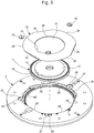
- the transparent part 10 is also in the form of a flat ring, and has a central opening 11 positioned concentrically with respect to the central disc 7 ( fig.3 ).
- the opening 11 is dimensioned so that the transparent part 10 covers an annular part 15 located on the periphery of the lower surface of the disc 7.
- the transparent part 10 covers an annular part 16 which is located on the inner periphery of the lower surface of the ring 2.
- the transparent part 10 is glued to said surface parts 15 and 16, so as to keep the ring 2 and the disc 7 integral with each other.
- the dial 1 therefore comprises an opaque ring 2, an opaque central disc 7, and an annular window between the disc 7 and the ring 2.
- the central disc 7 is provided with a circular portion 17 extending in relief relative to the part 15 which is covered by the transparent part 10.
- the diameter of the raised portion 17 corresponds to the opening diameter 11, allowing the workpiece to be positioned transparent 10 around the raised portion 17.
- the raised portion 17 comprises a radial projection 18, configured to engage in a radial notch 19 provided in the inner edge 20 of the transparent part 10, so that the The assembly of the transparent part 10 to the disc 7 is only possible in a single determined angular position of the transparent part 10 relative to the disc 7.
- the outer edge of the transparent part 10 comprises three straight parts 25 distributed at equal angular distances around the periphery of the part 10, while the rest of the edge consists of 3 curved portions 26 which are arcs of a circle.
- the annular part 16 of the ring 2 which will be covered by the transparent part 10 is positioned set back relative to the rear surface of the ring 2.
- Said annular part 16 is also provided with complementary straight 25 'and curved parts 26'. which correspond to the straight and curved parts 25,26 of the transparent part 10, allowing the positioning of the transparent part 10 inside the recessed part 16 by aligning the straight 25,25 'and curved parts 26,26'.
- the lower surface of the ring 2 further comprises recessed zones 27 located on the periphery of part 16, and provided with threaded holes 28 formed at the bottom of said zones 27.
- the holes 28 are configured to receive fixing screws 29 intended to achieve or contribute to the fixing of the transparent part 10 to the ring 2.
- the fixing is carried out by the heads of the fixing screws 29 which will be housed in the recessed areas 27, overlapping the edge of part 10, when screws 29 are tightened, so as to fix part 10 to ring 2.
- the assembly of the dial 1 shown in the figures is preferably carried out in two stages. We begin by assembling the transparent part 10 on the central disc 7, by aligning the projection 18 and the notch 19 and by placing the part 10 around the raised portion 17 and in contact with the surface part 15, after applying an adhesive to at least one of the contact surfaces.
- a glue that can be used in the case of a titanium disc 7 and a transparent part 10 of PMMA is Epsilon 2103 glue from APM Technica.
- the assembly formed by the part 10 and the disc 7 is then fixed to the surface portion 16 set back from the ring 2, by again applying an adhesive on at least one of the contact surfaces of the transparent part 10 and of part 16 of ring 2. Then the fixing screws 29 are clamped in the threaded holes 28, preferably after applying an adhesive to the surface of the recessed areas 27 in which the screw heads will be housed.
- the glue used between the transparent part 10 and the ring 2 can be of the same type as the glue used between the part 10 and the central disc 7. Alternatively, a weaker glue is used between the transparent part 10 and the ring 2 that between the part 10 and the disc 7.
- the term “weaker glue” is understood to mean an glue which has lower strength when the assembly is subjected to a determined impact.
- the transparent part 10 is not glued to the ring 2 but is fixed to the ring 2 only by the fixing screws 29.
- the fixing screws 29 are omitted, and the transparent part 10 is glued to the disc 7 as well as to the ring 2.
- the glue used between the transparent part 10 and the ring 2 can be as strong as the glue between the part 10 and the disc 7, or less strong.
- the embodiments in which a weaker adhesive is used between the transparent part 10 and the ring 2 than between the part 10 and the disc 7, or in which the transparent part 10 is not fixed to the ring 2 that by the fixing screws 29 have the advantage that the resistance of the dial to impact is improved, thanks to the fact that the deformability of the transparent part 10 relative to the ring 2 increases.
- the dome-shaped deformation (umbrella effect) of the dial is limited in the event of impacts and which can cause the hands to loosen.
- a watch provided with the dial described above is shown at figure 4 .
- the watch comprises hour and minute hands 30 and 31, which move above the dial to indicate the time and which are rotated conventionally by a clockwork movement (not shown), as well as a twenty-four hour annular disc 32, also rotated by said movement which moves below dial 1.
- the twenty-four hour disc 32 is provided with 24 markings distributed regularly over its surface. The markings are aligned with the annular zone between the central disc 7 and the ring 2, so as to visualize these markings through the window created by the transparent part 10.
- the twenty-four hour disc 32 is driven and corrected by mechanisms generally known simultaneously with the hour hand and minutes.
- the watch also includes an annular date disc aligned with window 12, also driven in a known manner.
- the central disc 7 can be provided with a decoration by engraving for example.
- the central disc 7, for example made of titanium, can be decorated using a typically femtosecond ultrashort pulse laser which makes it possible to sculpt nanostructures on the surface of the disc which selectively reflect certain wavelengths of visible light and therefore allow coloring.
- the transparent part 10 could have the shape of a solid disc instead of a ring. Instead of or in addition to adhesives and fixing screws, other fixing means could be applied to secure the transparent part 10 to the disc 7 and / or to the ring 2.
- the transparent part 10 could be fixed to the surface. upper instead of the lower surface of disc 7 and / or ring 2.
Landscapes
- Physics & Mathematics (AREA)
- General Physics & Mathematics (AREA)
- Electromechanical Clocks (AREA)
- Electric Clocks (AREA)
Abstract
Description
- La présente invention se rapporte à l'horlogerie, plus particulièrement à un cadran utilisable dans une pièce d'horlogerie à affichage de l'heure universelle.
- Une montre universelle permet d'afficher simultanément l'heure courante dans les différents fuseaux horaires du monde. Une telle montre comprend d'habitude un cadran fixe, des aiguilles d'heures et de minutes entrainées qui se déplacent au-dessus du cadran dans le sens horaire, à raison d'un tour en12H et un tour en 1H respectivement, un disque de vingt-quatre heures et un disque concentrique cadran et au disque de 24H comportant les noms de villes ou localisations mondiales qui représentent les différents fuseaux horaires. Le disque de vingt-quatre heures est relié à l'aiguille des heures par un engrenage, de manière à tourner à raison d'un tour par 24H dans le sens anti-horaire, l'heure d'une localisation étant indiquée par la division du disque de 24H qui se trouve en regard de ladite localisation. Dans la plupart des cas, le cadran, et le disque comportant les noms de villes sont des pièces indépendantes les unes des autres, le cadran se trouvant généralement au centre solidaire du mouvement et le disque de 24H et le disque des villes entourant successivement et de manière coplanaire le cadran central. Une telle construction présente notamment l'inconvénient de nécessiter l'adaptation de la partie supérieure du mouvement notamment pour disposer le cadran.
- La présente invention vise à fournir un cadran qui ne souffre pas des désavantages identifiés ci-dessus. Ce but est atteint par un cadran selon les revendications annexées. L'invention concerne également une pièce d'horlogerie telle qu'une montre, équipée d'un cadran selon l'invention. Un cadran selon l'invention comprend un anneau sous forme d'une plaque annulaire, un disque central monté de manière concentrique et essentiellement coplanaire par rapport à l'anneau, le diamètre du disque central étant inférieur au diamètre interne de l'anneau de manière à former une zone annulaire entre les deux, et une pièce transparente qui couvre ladite zone annulaire. En outre, la pièce transparente est fixée au disque et à l'anneau de manière à solidariser ces éléments entre eux. Le cadran est utilisable dans une pièce d'horlogerie à affichage du temps universel, et permet de monter de manière simple un disque vingt-quatre heures sur le mouvement en dessous du cadran, et de rendre les marquages sur le disque vingt-quatre heures visibles à travers la pièce transparente.
- Des caractéristiques et avantages spécifiques de la présente invention apparaîtront dans la description suivante de modes de réalisation préférés, présentés à titre d'exemple non limitatif en référence aux dessins annexés
-
- La
figure 1 représente une vue de face d'un cadran de montre selon une forme d'exécution préférée de l'invention. - La
figure 2 présente une vue en coupe selon la section A-A indiquée à lafigure 1 . - La
figure 3 représente une vue éclatée des composants du cadran montré dans lesfigures 1 et 2 . - La
figure 4 représente une montre équipée du cadran représenté à lafigure 1 . - Le cadran 1 représenté dans les
figures 1 et 2 comprend trois parties solidarisées entre elles de manière à former une pièce une seule solidaire. Le cadran est utilisable pour une montre bracelet. Le cadran 1 comprend un anneau plat 2, de préférence métallique, sous forme d'une plaque annulaire ayant un diamètre externe D1 et un diamètre interne D2. Dans la forme d'exécution des figures, l'anneau 2 comporte douze index 3 fixées à la surface supérieure de l'anneau 2, par des pieds de fixation 4 (voirfig. 2 ). On entend ici par surface supérieure celle destinée à être positionnée en regard de la glace de montre et par surface inférieure la surface opposée. Les positions des index 3 indiquent les positions des heures de 1 à 12. L'anneau 2 porte également les noms de 24 villes répartis de manière régulière sur le pourtour de l'anneau 2, les noms de villes correspondant aux 24 fuseaux horaires du monde. Les noms sont gravés dans la surface supérieure de l'anneau 2 et sur la surface d'un anneau additionnel 5 ayant une surface inclinée par rapport au plan de l'anneau 2. L'anneau additionnel est fixé sur ladite surface supérieure de l'anneau 2 par des pieds de fixation 6. - Dans le cas spécifique représenté à la
figure 1 , l'anneau 2 comprend également un guichet 12 disposé à 6 heures pour afficher le quantième. L'anneau 2 est réalisé dans un matériau opaque, par exemple, dans un alliage métallique tel que le CuZn33. De manière concentrique par rapport à l'anneau 2, et essentiellement dans le même plan que l'anneau 2, un disque central 7, de préférence métallique, est monté, réalisé également dans un matériau opaque, par exemple en titane, et comportant un trou central 8 pour le passage d'axes rotatifs qui portent les aiguilles d'heures et de minutes d'une montre. Le diamètre D3 du disque central 7 est inférieur au diamètre interne D2 de l'anneau 2, ce qui laisse apparaître une zone annulaire 9 entre le disque 7 et l'anneau 2. Ladite zone annulaire 9 est couverte par une pièce 10 réalisée dans un matériau transparent, tel qu'en PMMA (polyméthacrylate de méthyle) ou en saphir. - Dans le cas spécifique représenté aux figures, la pièce transparente 10 est également en forme d'anneau plat, et présente une ouverture centrale 11 positionnée de manière concentrique par rapport au disque central 7 (
fig.3 ). L'ouverture 11 est dimensionnée de sorte que la pièce transparente 10 recouvre une partie annulaire 15 située en périphérie de la surface inférieure du disque 7. Du côté opposé à l'ouverture 11 en direction radiale, la pièce transparente 10 recouvre une partie annulaire 16 qui se trouve en périphérie intérieure de la surface inférieure de l'anneau 2. La pièce transparente 10 est collée sur lesdites parties de surface 15 et 16, de manière à maintenir l'anneau 2 et le disque 7 solidaires entre eux. Vu en plan à lafigure 1 , le cadran 1 comporte donc un anneau opaque 2, un disque central opaque 7, et une fenêtre annulaire entre le disque 7 et l'anneau 2. - La vue éclatée de la
figure 3 dévoile des caractéristiques spécifiques de cette forme d'exécution. On voit que sur sa surface inférieure, le disque central 7 est pourvu d'une portion 17 circulaire s'étendant en relief par rapport à la partie 15 qui est recouverte par la pièce transparente 10. Le diamètre de la portion en relief 17 correspond au diamètre de l'ouverture 11, permettant le positionnement de la pièce transparente 10 autour de la portion en relief 17. En outre, la portion en relief 17 comprend une saillie radiale 18, configurée pour s'engager dans une encoche radiale 19 ménagée dans le bord interne 20 de la pièce transparente 10, de sorte que l'assemblage de la pièce transparente 10 au disque 7 n'est possible qu'en une seule position angulaire déterminée de la pièce transparente 10 par rapport au disque 7. - On voit également que le bord extérieur de la pièce transparente 10 comprend trois parties droites 25 réparties à distances angulaires égales sur le pourtour de la pièce 10, alors que le reste du bord est constitué de 3 portions courbées 26 qui sont des arcs de cercle. La partie annulaire 16 de l'anneau 2 qui sera recouverte par la pièce transparente 10 est positionnée en retrait par rapport à la surface arrière de l'anneau 2. Ladite partie annulaire 16 est également pourvue de parties droites 25' et courbées 26' complémentaires qui correspondent aux parties droites et courbées 25,26 de la pièce transparente 10, permettant le positionnement de la pièce transparente 10 à l'intérieur de la partie en retrait 16 en alignant les parties droites 25,25' et courbées 26,26'. Dans cette forme d'exécution, la surface inférieure de l'anneau 2 comprend en outre des zones en creux 27 situées en périphérie de la partie 16, et pourvues de trous filetés 28 ménagés au fond desdites zones 27. Les trous 28 sont configurés pour recevoir des vis de fixation 29 destinées à réaliser ou contribuer à la fixation de la pièce transparente 10 à l'anneau 2. La fixation est réalisée par les têtes des vis de fixation 29 qui vont se loger dans les zones en creux 27, en chevauchant le bord de la pièce 10, lorsque les vis 29 sont serrées, de manière à fixer la pièce 10 à l'anneau 2.
- L'assemblage du cadran 1 montré dans les figures est préférentiellement réalisé en deux étapes. On commence par l'assemblage de la pièce transparente 10 sur le disque central 7, en alignant la saillie 18 et l'encoche 19 et en plaçant la pièce 10 autour de la portion en relief 17 et en contact avec la partie de surface 15, après l'application d'une colle sur au moins une des surfaces de contact. Une colle utilisable dans le cas d'un disque 7 en titane et une pièce transparente 10 en PMMA est la colle Epsilon 2103 de APM Technica. L'ensemble formé par la pièce 10 et le disque 7 est ensuite fixé sur la partie de surface 16 en retrait de l'anneau 2, en appliquant de nouveau une colle sur au moins une des surfaces de contact de la pièce transparente 10 et de la partie 16 de l'anneau 2. Ensuite, les vis de fixation 29 sont serrées dans les trous filetés 28, de préférence après application d'une colle sur la surface des zones en creux 27 dans lesquelles les têtes de vis seront logées.
- La colle utilisée entre la pièce transparente 10 et l'anneau 2 peut être du même type que la colle utilisée entre la pièce 10 et le disque central 7. De manière alternative, une colle moins forte est utilisée entre la pièce transparente 10 et l'anneau 2 qu'entre la pièce 10 et le disque 7. Par colle moins forte on entend une colle qui présente une tenue inférieure lorsque l'assemblage est soumis à un choc déterminé.
- Selon encore une autre forme, la pièce transparente 10 n'est pas collée à l'anneau 2 mais elle est fixée à l'anneau 2 uniquement par les vis de fixation 29.
- Selon encore une autre forme d'exécution, les vis de fixation 29 sont supprimées, et la pièce transparente 10 est collée au disque 7 ainsi qu'à l'anneau 2. Dans cette dernière forme, la colle utilisée entre la pièce transparente 10 et l'anneau 2 peut être aussi forte que la colle entre la pièce 10 et le disque 7, ou moins forte.
- Les formes d'exécution dans lesquelles une colle moins forte est utilisée entre la pièce transparente 10 et l'anneau 2 qu'entre la pièce 10 et le disque 7, ou dans lesquelles la pièce transparente 10 n'est fixée à l'anneau 2 que par les vis de fixation 29 ont comme avantage que la résistance du cadran au chocs est améliorée, grâce au fait que la déformabilité de la pièce transparente 10 par rapport à l'anneau 2 augmente. On limite en particulier la déformation en forme de dôme (effet parapluie) du cadran en cas de chocs et qui peut induire un déchaussage des aiguilles
- Une montre pourvue du cadran décrit ci-dessus est représentée à la
figure 4 . La montre comprend des aiguilles d'heures et de minutes 30 et 31, qui se déplacent au-dessus du cadran pour indiquer l'heure et qui sont entrainées en rotation classiquement par un mouvement d'horlogerie (non représenté), ainsi qu'un disque annulaire de vingt-quatre heures 32, également entrainé en rotation par ledit mouvement qui se déplace en-dessous du cadran 1. Le disque de vingt-quatre heures 32 est pourvu de 24 marquages répartis régulièrement sur sa surface. Les marquages sont alignés avec la zone annulaire entre le disque central 7 et l'anneau 2, de manière à visualiser ces marquages à travers la fenêtre créée par la pièce transparente 10. Le disque vingt-quatre heures 32 est entrainé et corrigé par des mécanismes connus généralement simultanément avec l'aiguille des heures et des minutes. La montre comprend également un disque annulaire de quantième alignés avec le guichet 12, entrainé également de manière connue. Le disque central 7 peut être pourvu d'une décoration par gravure par exemple. Typiquement le disque central 7 par exemple en titane peut être décoré à l'aide d'un laser à impulsions ultracourtes typiquement femtoseconde qui permettent de sculpter des nanostructures à la surface du disque qui réfléchissent sélectivement certaines longueurs d'onde de la lumière visible et donc permettent une coloration. - L'homme de l'art comprend que des variantes de certaines caractéristiques du cadran décrit ci-dessus sont inclues dans la portée de l'invention. La pièce transparente 10 pourrait avoir la forme d'un disque plein au lieu d'un anneau. Au lieu de ou en plus des colles et vis de fixation, d'autres moyens de fixation pourraient être appliqués pour solidariser la pièce transparente 10 au disque 7 et/ou à l'anneau 2. La pièce transparente 10 pourrait être fixée sur la surface supérieure au lieu de la surface inférieure du disque 7 et/ou de l'anneau 2.
Claims (16)
- Cadran (1) pour une pièce d'horlogerie, le cadran comprenant :- Un anneau plat (2) en matériau opaque, ayant un diamètre externe (D1) et un diamètre interne (D2), l'anneau comprenant une surface supérieure et une surface inférieure,- Un disque central (7) en matériau opaque ayant un diamètre (D3) qui est inférieur au diamètre interne (D2) de l'anneau (2), le disque central étant positionné de manière concentrique par rapport à l'anneau (2) et essentiellement coplanaire avec l'anneau (2), de sorte qu'une zone annulaire (9) est créée entre le disque (7) et l'anneau (2), le disque central (7) comprenant une surface supérieure et une surface inférieure orientées respectivement comme la surface supérieure et la surface inférieure de l'anneau plat (2),- Une pièce en matériau transparent (10) qui couvre la zone annulaire (9) et qui est fixée au disque central (7) et à l'anneau (2), de manière à solidariser l'anneau (2) et le disque central (7), tout en réalisant une fenêtre annulaire entre le disque (7) et l'anneau (2).
- Le cadran selon la revendication 1, dans lequel la pièce transparente (10) recouvre au moins une partie (15) de la surface supérieure ou inférieure du disque central (7), et dans lequel la pièce transparente (10) est fixée au disque central (7) par collage de la pièce transparente (10) à ladite partie (15) de surface.
- Le cadran selon la revendication 2, dans lequel ladite partie de surface (15) du disque central (7), recouverte par la pièce transparente (10) est une partie annulaire (15) qui se trouve en périphérie de la surface supérieure ou inférieure du disque central (7).
- Le cadran selon la revendication 3, dans lequel la pièce transparente (10) a une forme plate et annulaire, ladite pièce (10) comprenant une ouverture centrale (11) positionnée de manière concentrique par rapport au disque central (7), et dimensionnée telle que la pièce transparente (10) recouvre ladite partie annulaire (15) en périphérie de la surface supérieure ou inférieure du disque central (7).
- Le cadran selon la revendication 4, dans lequel le disque central (7) comprend une portion en relief (17) encadrée par la partie annulaire (15), la portion en relief (17) étant dimensionnée telle que l'ouverture (11) est positionnée autour de ladite portion en relief (17).
- Le cadran selon la revendication 5, dans lequel l'ouverture (11) et la portion en relief (17) sont pourvues respectivement d'une saillie radiale (18) et d'une encoche radiale (19) ou vice versa, la saillie (18) étant configurée pour s'engager dans l'encoche (19), de manière à ne permettre l'assemblage de la pièce transparente (10) au disque central (7) qu'en une seule position angulaire de ladite pièce (10) par rapport au disque central (7).
- Le cadran selon l'une quelconque des revendications précédentes, dans lequel la pièce transparente (10) recouvre au moins une partie (16) de la surface supérieure ou inférieure de l'anneau (2), et dans lequel la pièce transparente (10) est fixée à l'anneau (2) par collage et/ou vissage de la pièce transparente (10) à ladite partie de surface (16) de l'anneau (2).
- Le cadran selon la revendication 7, dans lequel ladite partie de surface (16) de l'anneau (2), recouverte par la pièce transparente (10), est une partie annulaire (16) qui se trouve en périphérie intérieure de la surface de l'anneau (2).
- Le cadran selon la revendication 8, dans lequel ladite partie annulaire (16) est positionnée en retrait par rapport au reste de ladite surface de l'anneau (2).
- Le cadran selon la revendication 9, dans lequel le bord externe de la pièce transparente (10) comprend des éléments géométriques (25,26) qui permettent un alignement angulaire de la pièce transparente (10) par rapport à l'anneau (2), et dans lequel ladite partie annulaire (16) comprend des éléments d'alignement (25',26') qui correspondent aux éléments géométriques (25,26) sur le bord externe de la pièce transparente (10).
- Le cadran selon l'une quelconque des revendication 8 à 10, dans lequel la pièce transparente (10) est fixée à l'anneau (2) à l'aide d'au moins une pluralité de vis de fixation (29) comprenant des têtes de vis qui chevauchent le bord externe de la pièce transparente (10).
- Le cadran selon l'une quelconque des revendications précédentes, dans lequel :- la pièce transparente (10) est fixée au disque central (7) par une première colle,- la pièce transparente (10) est fixée à l'anneau (2) au moins par une deuxième colle,- la deuxième colle est moins forte que la première colle.
- Le cadran selon l'une quelconque des revendications 1 à 11, dans lequel :- la pièce transparente (10) est fixée au disque central (7) par une première colle,- la pièce transparente (10) est fixée à l'anneau (2) par vissage, sans l'application d'une colle.
- Le cadran selon l'une quelconque des revendications précédentes, dans lequel l'anneau (2) comprend sur sa surface supérieure une pluralité de noms de localisations mondiales qui représentent les fuseaux horaires du monde.
- Une pièce d'horlogerie comportant un cadran (1) selon l'une quelconque des revendications précédentes.
- La pièce d'horlogerie selon la revendication 15, dans lequel le cadran (1) comprend sur la surface supérieure de l'anneau (2) une pluralité de noms de localisations mondiales qui représentent les fuseaux horaires du monde, et dans lequel la pièce d'horlogerie comprend en dessous du cadran (1) un disque vingt-quatre heures (32) pour marquer le temps universel au moyen d'une pluralité de marquages répartis sur le disque vingt-quatre heures, et dans lequel les marquages sont alignés avec la zone annulaire (9) entre le disque (7) et l'anneau (2) du cadran.
Priority Applications (4)
| Application Number | Priority Date | Filing Date | Title |
|---|---|---|---|
| EP19163830.3A EP3712714B1 (fr) | 2019-03-19 | 2019-03-19 | Cadran pour une montre universelle |
| US16/794,333 US11579567B2 (en) | 2019-03-19 | 2020-02-19 | Dial for a universal watch |
| JP2020029067A JP7029482B2 (ja) | 2019-03-19 | 2020-02-25 | 世界時を表示する携行型時計のための表盤 |
| CN202010165471.3A CN111722516B (zh) | 2019-03-19 | 2020-03-11 | 世界时手表的表盘 |
Applications Claiming Priority (1)
| Application Number | Priority Date | Filing Date | Title |
|---|---|---|---|
| EP19163830.3A EP3712714B1 (fr) | 2019-03-19 | 2019-03-19 | Cadran pour une montre universelle |
Publications (2)
| Publication Number | Publication Date |
|---|---|
| EP3712714A1 true EP3712714A1 (fr) | 2020-09-23 |
| EP3712714B1 EP3712714B1 (fr) | 2022-11-30 |
Family
ID=65904002
Family Applications (1)
| Application Number | Title | Priority Date | Filing Date |
|---|---|---|---|
| EP19163830.3A Active EP3712714B1 (fr) | 2019-03-19 | 2019-03-19 | Cadran pour une montre universelle |
Country Status (4)
| Country | Link |
|---|---|
| US (1) | US11579567B2 (fr) |
| EP (1) | EP3712714B1 (fr) |
| JP (1) | JP7029482B2 (fr) |
| CN (1) | CN111722516B (fr) |
Families Citing this family (2)
| Publication number | Priority date | Publication date | Assignee | Title |
|---|---|---|---|---|
| USD1090282S1 (en) * | 2023-08-21 | 2025-08-26 | Blancpain Sa | Watch |
| JP1806741S (ja) * | 2024-01-08 | 2025-08-21 | 時計本体 |
Citations (3)
| Publication number | Priority date | Publication date | Assignee | Title |
|---|---|---|---|---|
| CH287290A (fr) * | 1950-11-10 | 1952-11-30 | Montres Helvetia Societe D Hor | Pièce d'horlogerie universelle. |
| DE1795193U (de) * | 1957-11-25 | 1959-09-03 | Werner Dossmann | Weltzeituhr. |
| EP3428737A1 (fr) * | 2017-07-11 | 2019-01-16 | ETA SA Manufacture Horlogère Suisse | Masse de remontage oscillante pour pièce d'horlogerie à mouvement automatique et pièce d'horlogerie équipée d'une telle masse de remontage |
Family Cites Families (28)
| Publication number | Priority date | Publication date | Assignee | Title |
|---|---|---|---|---|
| US3472021A (en) * | 1967-04-06 | 1969-10-14 | Hajime Karakawa | World time clock system |
| CH543514A (de) | 1967-08-25 | 1973-10-31 | Hoffmann La Roche | Verfahren zur Herstellung von Morphinanderivaten |
| JPS551754U (fr) | 1978-06-20 | 1980-01-08 | ||
| JPS6259888A (ja) | 1985-09-10 | 1987-03-16 | Matsushita Electric Ind Co Ltd | 時計 |
| JPS62186091U (fr) * | 1986-05-20 | 1987-11-26 | ||
| US5146436A (en) * | 1991-08-09 | 1992-09-08 | Wright James B | Universal world clock |
| CH684619B5 (fr) | 1992-07-17 | 1995-05-15 | Longines Montres Comp D | Pièce d'horlogerie à affichage universel de l'heure. |
| CH684916B5 (de) * | 1993-02-24 | 1995-09-15 | Bruno Hotz | Uhr mit Weltzeitanzeige. |
| JPH072992U (ja) * | 1993-03-04 | 1995-01-17 | 勝之助 武田 | イロハ時計 |
| JPH10282274A (ja) * | 1997-04-04 | 1998-10-23 | Seiko Instr Inc | コンビネーション電子時計 |
| US5917778A (en) * | 1997-09-25 | 1999-06-29 | Cube-I, L.L.C. | Geographical chronological device |
| JP3810536B2 (ja) * | 1997-11-18 | 2006-08-16 | シチズン時計株式会社 | ソーラー時計用表示板構造 |
| JP4275804B2 (ja) | 1999-05-17 | 2009-06-10 | シチズンホールディングス株式会社 | 表示板構造 |
| JP4599637B2 (ja) | 1999-09-30 | 2010-12-15 | カシオ計算機株式会社 | 時計用文字板および時計 |
| CN2692717Y (zh) | 2004-03-22 | 2005-04-13 | 王鍊登 | 可直读世界时间的读览盘 |
| CN1588240A (zh) | 2004-07-14 | 2005-03-02 | 陈黎明 | 可调式国际钟表 |
| CN1725130A (zh) * | 2004-07-25 | 2006-01-25 | 窦迎峰 | 世界钟 |
| EP1640822B1 (fr) | 2004-09-22 | 2012-08-01 | Asulab S.A. | Cadran émaillé multi-étages |
| US20060171256A1 (en) * | 2005-02-03 | 2006-08-03 | Keith Herbert | Global timepiece with double day/double date rendering |
| TWI461865B (zh) * | 2006-06-23 | 2014-11-21 | Omega Sa | 用於機械式時計機心之擺輪游絲調節系統及具有此系統之時計 |
| CN201251686Y (zh) * | 2008-07-21 | 2009-06-03 | 张洪平 | 世界时钟表盘 |
| US8221125B2 (en) | 2008-08-14 | 2012-07-17 | World View Time Inc. | Electronic presentation of world time zones |
| CH703122B1 (fr) * | 2010-05-11 | 2015-01-15 | Omega Sa | Outillage pour l'extraction de lunettes de montres. |
| CN203250138U (zh) | 2013-07-22 | 2013-10-23 | 刘小勇 | 一种世界时钟 |
| CN203365946U (zh) | 2013-09-18 | 2013-12-25 | 梁梅梅 | 一种可间接读取世界时间的手表 |
| CN204347449U (zh) | 2014-12-30 | 2015-05-20 | 北京工业大学 | 世界钟表 |
| CN107817672A (zh) | 2017-11-27 | 2018-03-20 | 上海新天始化工包装科研所 | 世界时钟 |
| CN207718152U (zh) | 2017-12-29 | 2018-08-10 | 严静一 | 一种能够同时显示全时区时间的时钟 |
-
2019
- 2019-03-19 EP EP19163830.3A patent/EP3712714B1/fr active Active
-
2020
- 2020-02-19 US US16/794,333 patent/US11579567B2/en active Active
- 2020-02-25 JP JP2020029067A patent/JP7029482B2/ja active Active
- 2020-03-11 CN CN202010165471.3A patent/CN111722516B/zh active Active
Patent Citations (3)
| Publication number | Priority date | Publication date | Assignee | Title |
|---|---|---|---|---|
| CH287290A (fr) * | 1950-11-10 | 1952-11-30 | Montres Helvetia Societe D Hor | Pièce d'horlogerie universelle. |
| DE1795193U (de) * | 1957-11-25 | 1959-09-03 | Werner Dossmann | Weltzeituhr. |
| EP3428737A1 (fr) * | 2017-07-11 | 2019-01-16 | ETA SA Manufacture Horlogère Suisse | Masse de remontage oscillante pour pièce d'horlogerie à mouvement automatique et pièce d'horlogerie équipée d'une telle masse de remontage |
Also Published As
| Publication number | Publication date |
|---|---|
| US11579567B2 (en) | 2023-02-14 |
| JP2020153972A (ja) | 2020-09-24 |
| CN111722516A (zh) | 2020-09-29 |
| EP3712714B1 (fr) | 2022-11-30 |
| JP7029482B2 (ja) | 2022-03-03 |
| US20200301364A1 (en) | 2020-09-24 |
| CN111722516B (zh) | 2024-05-28 |
Similar Documents
| Publication | Publication Date | Title |
|---|---|---|
| EP0957414B1 (fr) | Masse de remontage oscillante pour pièce d'horlogerie à mouvement automatique et pièce d'horlogerie équipée d'une telle masse de remontage | |
| EP2859412B1 (fr) | Systeme de lunette tournante | |
| EP1950632A1 (fr) | Montre à lunette polygonale | |
| CH705244B1 (fr) | Pièce d'horlogerie. | |
| EP3680729B1 (fr) | Fond orientable pour une piece d'horlogerie | |
| EP3712714B1 (fr) | Cadran pour une montre universelle | |
| EP2737372B1 (fr) | Masse oscillante pivotée sur l'extérieur d'un mouvement d'horlogerie, mouvement d'horlogerie équipé d'une telle masse oscillante et pièce d'horlogerie comprenant une telle masse oscillante | |
| EP1975747B1 (fr) | Boîte de montre | |
| CH684814B5 (fr) | Pièce d'horlogerie pourvue d'un tour d'heures à présentation modifiable. | |
| CH715978A2 (fr) | Cadran pour une montre universelle. | |
| EP0626625A1 (fr) | Boîte de montre en métal noble | |
| CH696089A5 (fr) | Ensemble de boîtes de montre et son procédé de fabrication. | |
| EP1923754B1 (fr) | Mouvement d'horlogerie équipé d'un module d'affichage | |
| EP1055157B1 (fr) | Montre a affichage analogique | |
| EP1241541B1 (fr) | Boîte de montre assemblée par la lunette | |
| EP4250020B1 (fr) | Boîte de montre à lunette tournante | |
| CH715720A2 (fr) | Fond orientable pour une pièce d'horlogerie. | |
| EP1980921B1 (fr) | Pièce d'horlogerie comportant une lunette tournante | |
| EP2156250B1 (fr) | Dispositif de correction d'un mecanisme d'affichage pour piece d'horlogerie | |
| WO2005088411A1 (fr) | Piece d’horlogerie avec affichage analogique mobile | |
| EP0255712B1 (fr) | Mouvement de montre électronique à affichage à aiguilles | |
| CH720791A2 (fr) | Mobile horloger | |
| CH720290B1 (fr) | Boitier de montre permettant de voir un mouvement dans son épaisseur | |
| CH716554B1 (fr) | Boîte de montre à lunette amovible. | |
| CH692630A5 (fr) | Engrenage avec position de blocage, notamment pour l'entraînement d'un indicateur d'un instrument horaire. |
Legal Events
| Date | Code | Title | Description |
|---|---|---|---|
| PUAI | Public reference made under article 153(3) epc to a published international application that has entered the european phase |
Free format text: ORIGINAL CODE: 0009012 |
|
| STAA | Information on the status of an ep patent application or granted ep patent |
Free format text: STATUS: THE APPLICATION HAS BEEN PUBLISHED |
|
| AK | Designated contracting states |
Kind code of ref document: A1 Designated state(s): AL AT BE BG CH CY CZ DE DK EE ES FI FR GB GR HR HU IE IS IT LI LT LU LV MC MK MT NL NO PL PT RO RS SE SI SK SM TR |
|
| AX | Request for extension of the european patent |
Extension state: BA ME |
|
| STAA | Information on the status of an ep patent application or granted ep patent |
Free format text: STATUS: REQUEST FOR EXAMINATION WAS MADE |
|
| 17P | Request for examination filed |
Effective date: 20210323 |
|
| RBV | Designated contracting states (corrected) |
Designated state(s): AL AT BE BG CH CY CZ DE DK EE ES FI FR GB GR HR HU IE IS IT LI LT LU LV MC MK MT NL NO PL PT RO RS SE SI SK SM TR |
|
| RIC1 | Information provided on ipc code assigned before grant |
Ipc: G04B 19/22 20060101AFI20220810BHEP |
|
| GRAP | Despatch of communication of intention to grant a patent |
Free format text: ORIGINAL CODE: EPIDOSNIGR1 |
|
| STAA | Information on the status of an ep patent application or granted ep patent |
Free format text: STATUS: GRANT OF PATENT IS INTENDED |
|
| INTG | Intention to grant announced |
Effective date: 20220922 |
|
| GRAS | Grant fee paid |
Free format text: ORIGINAL CODE: EPIDOSNIGR3 |
|
| GRAA | (expected) grant |
Free format text: ORIGINAL CODE: 0009210 |
|
| STAA | Information on the status of an ep patent application or granted ep patent |
Free format text: STATUS: THE PATENT HAS BEEN GRANTED |
|
| AK | Designated contracting states |
Kind code of ref document: B1 Designated state(s): AL AT BE BG CH CY CZ DE DK EE ES FI FR GB GR HR HU IE IS IT LI LT LU LV MC MK MT NL NO PL PT RO RS SE SI SK SM TR |
|
| REG | Reference to a national code |
Ref country code: CH Ref legal event code: EP Ref country code: GB Ref legal event code: FG4D Free format text: NOT ENGLISH |
|
| REG | Reference to a national code |
Ref country code: AT Ref legal event code: REF Ref document number: 1535138 Country of ref document: AT Kind code of ref document: T Effective date: 20221215 Ref country code: DE Ref legal event code: R096 Ref document number: 602019022412 Country of ref document: DE |
|
| REG | Reference to a national code |
Ref country code: IE Ref legal event code: FG4D Free format text: LANGUAGE OF EP DOCUMENT: FRENCH |
|
| REG | Reference to a national code |
Ref country code: LT Ref legal event code: MG9D |
|
| REG | Reference to a national code |
Ref country code: NL Ref legal event code: MP Effective date: 20221130 |
|
| PG25 | Lapsed in a contracting state [announced via postgrant information from national office to epo] |
Ref country code: SE Free format text: LAPSE BECAUSE OF FAILURE TO SUBMIT A TRANSLATION OF THE DESCRIPTION OR TO PAY THE FEE WITHIN THE PRESCRIBED TIME-LIMIT Effective date: 20221130 Ref country code: PT Free format text: LAPSE BECAUSE OF FAILURE TO SUBMIT A TRANSLATION OF THE DESCRIPTION OR TO PAY THE FEE WITHIN THE PRESCRIBED TIME-LIMIT Effective date: 20230331 Ref country code: NO Free format text: LAPSE BECAUSE OF FAILURE TO SUBMIT A TRANSLATION OF THE DESCRIPTION OR TO PAY THE FEE WITHIN THE PRESCRIBED TIME-LIMIT Effective date: 20230228 Ref country code: LT Free format text: LAPSE BECAUSE OF FAILURE TO SUBMIT A TRANSLATION OF THE DESCRIPTION OR TO PAY THE FEE WITHIN THE PRESCRIBED TIME-LIMIT Effective date: 20221130 Ref country code: FI Free format text: LAPSE BECAUSE OF FAILURE TO SUBMIT A TRANSLATION OF THE DESCRIPTION OR TO PAY THE FEE WITHIN THE PRESCRIBED TIME-LIMIT Effective date: 20221130 Ref country code: ES Free format text: LAPSE BECAUSE OF FAILURE TO SUBMIT A TRANSLATION OF THE DESCRIPTION OR TO PAY THE FEE WITHIN THE PRESCRIBED TIME-LIMIT Effective date: 20221130 |
|
| REG | Reference to a national code |
Ref country code: AT Ref legal event code: MK05 Ref document number: 1535138 Country of ref document: AT Kind code of ref document: T Effective date: 20221130 |
|
| PG25 | Lapsed in a contracting state [announced via postgrant information from national office to epo] |
Ref country code: RS Free format text: LAPSE BECAUSE OF FAILURE TO SUBMIT A TRANSLATION OF THE DESCRIPTION OR TO PAY THE FEE WITHIN THE PRESCRIBED TIME-LIMIT Effective date: 20221130 Ref country code: PL Free format text: LAPSE BECAUSE OF FAILURE TO SUBMIT A TRANSLATION OF THE DESCRIPTION OR TO PAY THE FEE WITHIN THE PRESCRIBED TIME-LIMIT Effective date: 20221130 Ref country code: LV Free format text: LAPSE BECAUSE OF FAILURE TO SUBMIT A TRANSLATION OF THE DESCRIPTION OR TO PAY THE FEE WITHIN THE PRESCRIBED TIME-LIMIT Effective date: 20221130 Ref country code: IS Free format text: LAPSE BECAUSE OF FAILURE TO SUBMIT A TRANSLATION OF THE DESCRIPTION OR TO PAY THE FEE WITHIN THE PRESCRIBED TIME-LIMIT Effective date: 20230330 Ref country code: HR Free format text: LAPSE BECAUSE OF FAILURE TO SUBMIT A TRANSLATION OF THE DESCRIPTION OR TO PAY THE FEE WITHIN THE PRESCRIBED TIME-LIMIT Effective date: 20221130 Ref country code: GR Free format text: LAPSE BECAUSE OF FAILURE TO SUBMIT A TRANSLATION OF THE DESCRIPTION OR TO PAY THE FEE WITHIN THE PRESCRIBED TIME-LIMIT Effective date: 20230301 |
|
| PG25 | Lapsed in a contracting state [announced via postgrant information from national office to epo] |
Ref country code: NL Free format text: LAPSE BECAUSE OF FAILURE TO SUBMIT A TRANSLATION OF THE DESCRIPTION OR TO PAY THE FEE WITHIN THE PRESCRIBED TIME-LIMIT Effective date: 20221130 |
|
| PG25 | Lapsed in a contracting state [announced via postgrant information from national office to epo] |
Ref country code: SM Free format text: LAPSE BECAUSE OF FAILURE TO SUBMIT A TRANSLATION OF THE DESCRIPTION OR TO PAY THE FEE WITHIN THE PRESCRIBED TIME-LIMIT Effective date: 20221130 Ref country code: RO Free format text: LAPSE BECAUSE OF FAILURE TO SUBMIT A TRANSLATION OF THE DESCRIPTION OR TO PAY THE FEE WITHIN THE PRESCRIBED TIME-LIMIT Effective date: 20221130 Ref country code: EE Free format text: LAPSE BECAUSE OF FAILURE TO SUBMIT A TRANSLATION OF THE DESCRIPTION OR TO PAY THE FEE WITHIN THE PRESCRIBED TIME-LIMIT Effective date: 20221130 Ref country code: DK Free format text: LAPSE BECAUSE OF FAILURE TO SUBMIT A TRANSLATION OF THE DESCRIPTION OR TO PAY THE FEE WITHIN THE PRESCRIBED TIME-LIMIT Effective date: 20221130 Ref country code: CZ Free format text: LAPSE BECAUSE OF FAILURE TO SUBMIT A TRANSLATION OF THE DESCRIPTION OR TO PAY THE FEE WITHIN THE PRESCRIBED TIME-LIMIT Effective date: 20221130 Ref country code: AT Free format text: LAPSE BECAUSE OF FAILURE TO SUBMIT A TRANSLATION OF THE DESCRIPTION OR TO PAY THE FEE WITHIN THE PRESCRIBED TIME-LIMIT Effective date: 20221130 |
|
| P01 | Opt-out of the competence of the unified patent court (upc) registered |
Effective date: 20230701 |
|
| PG25 | Lapsed in a contracting state [announced via postgrant information from national office to epo] |
Ref country code: SK Free format text: LAPSE BECAUSE OF FAILURE TO SUBMIT A TRANSLATION OF THE DESCRIPTION OR TO PAY THE FEE WITHIN THE PRESCRIBED TIME-LIMIT Effective date: 20221130 Ref country code: AL Free format text: LAPSE BECAUSE OF FAILURE TO SUBMIT A TRANSLATION OF THE DESCRIPTION OR TO PAY THE FEE WITHIN THE PRESCRIBED TIME-LIMIT Effective date: 20221130 |
|
| REG | Reference to a national code |
Ref country code: DE Ref legal event code: R097 Ref document number: 602019022412 Country of ref document: DE |
|
| PLBE | No opposition filed within time limit |
Free format text: ORIGINAL CODE: 0009261 |
|
| STAA | Information on the status of an ep patent application or granted ep patent |
Free format text: STATUS: NO OPPOSITION FILED WITHIN TIME LIMIT |
|
| PG25 | Lapsed in a contracting state [announced via postgrant information from national office to epo] |
Ref country code: MC Free format text: LAPSE BECAUSE OF FAILURE TO SUBMIT A TRANSLATION OF THE DESCRIPTION OR TO PAY THE FEE WITHIN THE PRESCRIBED TIME-LIMIT Effective date: 20221130 |
|
| 26N | No opposition filed |
Effective date: 20230831 |
|
| PG25 | Lapsed in a contracting state [announced via postgrant information from national office to epo] |
Ref country code: SI Free format text: LAPSE BECAUSE OF FAILURE TO SUBMIT A TRANSLATION OF THE DESCRIPTION OR TO PAY THE FEE WITHIN THE PRESCRIBED TIME-LIMIT Effective date: 20221130 |
|
| REG | Reference to a national code |
Ref country code: BE Ref legal event code: MM Effective date: 20230331 |
|
| PG25 | Lapsed in a contracting state [announced via postgrant information from national office to epo] |
Ref country code: LU Free format text: LAPSE BECAUSE OF NON-PAYMENT OF DUE FEES Effective date: 20230319 |
|
| REG | Reference to a national code |
Ref country code: IE Ref legal event code: MM4A |
|
| PG25 | Lapsed in a contracting state [announced via postgrant information from national office to epo] |
Ref country code: IE Free format text: LAPSE BECAUSE OF NON-PAYMENT OF DUE FEES Effective date: 20230319 |
|
| PG25 | Lapsed in a contracting state [announced via postgrant information from national office to epo] |
Ref country code: BE Free format text: LAPSE BECAUSE OF NON-PAYMENT OF DUE FEES Effective date: 20230331 |
|
| PG25 | Lapsed in a contracting state [announced via postgrant information from national office to epo] |
Ref country code: IT Free format text: LAPSE BECAUSE OF FAILURE TO SUBMIT A TRANSLATION OF THE DESCRIPTION OR TO PAY THE FEE WITHIN THE PRESCRIBED TIME-LIMIT Effective date: 20221130 |
|
| PG25 | Lapsed in a contracting state [announced via postgrant information from national office to epo] |
Ref country code: BG Free format text: LAPSE BECAUSE OF FAILURE TO SUBMIT A TRANSLATION OF THE DESCRIPTION OR TO PAY THE FEE WITHIN THE PRESCRIBED TIME-LIMIT Effective date: 20221130 |
|
| PG25 | Lapsed in a contracting state [announced via postgrant information from national office to epo] |
Ref country code: BG Free format text: LAPSE BECAUSE OF FAILURE TO SUBMIT A TRANSLATION OF THE DESCRIPTION OR TO PAY THE FEE WITHIN THE PRESCRIBED TIME-LIMIT Effective date: 20221130 |
|
| PGFP | Annual fee paid to national office [announced via postgrant information from national office to epo] |
Ref country code: CH Payment date: 20250401 Year of fee payment: 7 |
|
| PG25 | Lapsed in a contracting state [announced via postgrant information from national office to epo] |
Ref country code: CY Free format text: LAPSE BECAUSE OF FAILURE TO SUBMIT A TRANSLATION OF THE DESCRIPTION OR TO PAY THE FEE WITHIN THE PRESCRIBED TIME-LIMIT; INVALID AB INITIO Effective date: 20190319 |
|
| PG25 | Lapsed in a contracting state [announced via postgrant information from national office to epo] |
Ref country code: HU Free format text: LAPSE BECAUSE OF FAILURE TO SUBMIT A TRANSLATION OF THE DESCRIPTION OR TO PAY THE FEE WITHIN THE PRESCRIBED TIME-LIMIT; INVALID AB INITIO Effective date: 20190319 |
|
| PG25 | Lapsed in a contracting state [announced via postgrant information from national office to epo] |
Ref country code: TR Free format text: LAPSE BECAUSE OF FAILURE TO SUBMIT A TRANSLATION OF THE DESCRIPTION OR TO PAY THE FEE WITHIN THE PRESCRIBED TIME-LIMIT Effective date: 20221130 |
|
| REG | Reference to a national code |
Ref country code: CH Ref legal event code: U11 Free format text: ST27 STATUS EVENT CODE: U-0-0-U10-U11 (AS PROVIDED BY THE NATIONAL OFFICE) Effective date: 20260401 |
|
| PGFP | Annual fee paid to national office [announced via postgrant information from national office to epo] |
Ref country code: GB Payment date: 20260219 Year of fee payment: 8 |
|
| PGFP | Annual fee paid to national office [announced via postgrant information from national office to epo] |
Ref country code: DE Payment date: 20260219 Year of fee payment: 8 |
|
| PGFP | Annual fee paid to national office [announced via postgrant information from national office to epo] |
Ref country code: FR Payment date: 20260219 Year of fee payment: 8 |