EP3712724A1 - Agencement d'automatisation, procédé de fonctionnement de l'agencement d'automatisation ainsi que programme informatique - Google Patents
Agencement d'automatisation, procédé de fonctionnement de l'agencement d'automatisation ainsi que programme informatique Download PDFInfo
- Publication number
- EP3712724A1 EP3712724A1 EP20164639.5A EP20164639A EP3712724A1 EP 3712724 A1 EP3712724 A1 EP 3712724A1 EP 20164639 A EP20164639 A EP 20164639A EP 3712724 A1 EP3712724 A1 EP 3712724A1
- Authority
- EP
- European Patent Office
- Prior art keywords
- programmable logic
- logic controller
- data
- automation
- module
- Prior art date
- Legal status (The legal status is an assumption and is not a legal conclusion. Google has not performed a legal analysis and makes no representation as to the accuracy of the status listed.)
- Withdrawn
Links
Images
Classifications
-
- G—PHYSICS
- G05—CONTROLLING; REGULATING
- G05B—CONTROL OR REGULATING SYSTEMS IN GENERAL; FUNCTIONAL ELEMENTS OF SUCH SYSTEMS; MONITORING OR TESTING ARRANGEMENTS FOR SUCH SYSTEMS OR ELEMENTS
- G05B19/00—Program-control systems
- G05B19/02—Program-control systems electric
- G05B19/04—Program control other than numerical control, i.e. in sequence controllers or logic controllers
- G05B19/05—Programmable logic controllers, e.g. simulating logic interconnections of signals according to ladder diagrams or function charts
-
- G—PHYSICS
- G05—CONTROLLING; REGULATING
- G05B—CONTROL OR REGULATING SYSTEMS IN GENERAL; FUNCTIONAL ELEMENTS OF SUCH SYSTEMS; MONITORING OR TESTING ARRANGEMENTS FOR SUCH SYSTEMS OR ELEMENTS
- G05B2219/00—Program-control systems
- G05B2219/10—Plc systems
- G05B2219/14—Plc safety
- G05B2219/14055—Make log, journal, history file of state changes
Definitions
- the invention relates to an automation arrangement having the features of the preamble of claim 1.
- the invention also relates to a method for operating the automation arrangement and a computer program.
- Programmable logic controllers are devices for controlling or regulating a machine or a system, which are programmed on a digital basis. Programmable logic controllers control industrial robots, for example, and implement movement paths for tools or components. Depending on the kinematics of the industrial robots, a large number of axes must be controlled synchronized in real time, so that the programmable logic controller has to implement strict real-time requirements.
- the pamphlet DE 2982111 U1 which probably relates to the closest prior art, relates to a battery monitoring charging device for a battery group of a battery-powered vehicle with a control unit, the control unit actively influencing the charging process as a function of measurement results.
- the control unit is designed as a SIMATIC-PLC, which thus implements a control circuit influenced by a real-time measurement result.
- the invention relates to an automation arrangement for automating processes, in particular industrial processes.
- the procedures can be used as Manufacturing processes, assembly processes, measuring processes, test processes, handling processes, etc.
- the automation arrangement has a programmable logic controller for controlling an automation system.
- the programmable logic controller can be referred to in short as a PLC or a PLC.
- the programmable logic controller is designed as a digital data processing device and / or in particular has at least one CPU.
- the automation system has at least one actuator and / or is designed in particular as an industrial robot with at least one, a few or a plurality of axes.
- the industrial robot can be equipped with grippers, tools or other production means and can carry out the above-mentioned processes.
- the programmable logic controller has a control module for generating control commands for the automation system.
- the control module is particularly preferably designed as a software module.
- the control commands are implemented in particular as real-time commands.
- the automation arrangement has a control interface for transferring the control commands to the automation system.
- the control interface is connected to the programmable logic controller in terms of data technology, so that the control commands can be generated in the programmable logic controller and output to the automation system via the control interface.
- the automation arrangement has a measurement interface which is designed to accept measurement data from a measurement device.
- the measurement interface is connected to the programmable logic controller in terms of data technology, so that the measurement data are transmitted from the measuring device to the programmable logic controller via the measurement interface can.
- the measuring device comprises in particular at least one or a few sensors, wherein the sensors in a general form of the invention can be designed as desired.
- the measurement data particularly preferably include status measurement and / or process measurement data from the workpiece, the tools, the grippers and / or from the manufacturing process and / or the measurement process and / or handling process.
- the measurement data can include process measurement data from the manufacturing process or measurement data from a measurement process.
- the programmable logic controller have an evaluation module for generating log data from the measurement data.
- the log data can be designed, for example, as evaluated and / or combined measurement data.
- the feeding of measurement data into the programmable logic controller has so far only been used to guide the automation system with sensor support if necessary, with controls and / or regulations being implemented based on the measurement data.
- the measurement data from the control unit from the prior art influence the further charging process of the battery unit.
- the evaluation module generate and provide protocol data from the measurement data. This not only makes it possible to control processes, but also, in particular offline, to log the processes and thus increase the quality of the process within the framework of quality management. It is thus possible to create the basis for a quality control loop on the basis of the programmable logic controller and / or to collect the required quality data.
- a second device for example with a separate measuring device, as measurement data and then to store it as log data.
- a second device for example with a separate measuring device
- the protocol function and the actual control function are implemented in a common programmable logic controller, so that when the automation system is started up, both functions can only be used in one programming environment.
- the operation of the automation arrangement can be simplified by combining the functions in the programmable logic controller. If one considers the economic aspect of the invention, then only one software environment, namely the software environment for the programmable logic controller, and no longer two different software environments for the control function and the log function have to be bought / rented, managed and maintained using the automation arrangement according to the invention.
- the programmable logic controller has a storage module for storing the log data in a preferably external memory. This further development opens up the possibility that the programmable logic controller not only generates the log data, but can also store them in a memory for documentation purposes.
- the log data are stored in a .DFD file.
- the .DFQ file includes features of the process and corresponding log data on the features, such as trends, deviations, warnings, etc.
- the automation arrangement has a display device for displaying control processes of the programmable logic controller. For example, axis positions, process sequences, etc. are shown on the display device.
- the display device is connected to the programmable logic controller in terms of data technology, so that the programmable logic controller can generate corresponding control display data and can transmit it to the display device.
- the programmable logic controller has a display module for generating log display data for the log data.
- the log display data can be displayed on the display device. This further development makes it possible that corresponding log data are not only generated in the background of the programmable logic controller, but that the log data can particularly preferably be displayed in real time on the display device. This enables a user of the automation arrangement to recognize deviations in the running process, which can be recognized by the log data, and to intervene in the running process in a corrective manner.
- the automation arrangement comprises the automation system and the measuring device, the measuring device receiving measurement data from the automation system.
- the programmable logic controller belongs to the SIMATIC family.
- This SIMATIC family is a product of Siemens AG and forms an industrial standard for programmable logic controllers.
- the programmable logic controller is particularly preferably designed as an S7, in particular an S7-1500, or as a successor model.
- a data connection between the programmable logic controller and the automation system and / or between the programmable logic controller and the measurement interface and / or between the programmable logic controller and the external memory and / or between the programmable logic controller and the Display device at least in sections or completely over a network, in particular over a Profibus takes place.
- the Profibus is also an established standard and allows the real-time exchange of control data, measurement data, display data and / or other data.
- the automation arrangement has a library, wherein the library can form an integral part of the programmable logic controller or can be stored on a separate, digital data processing device.
- the evaluation module and / or the storage module and / or the control module is or are each designed as a library module and / or PLC module in the library.
- Such library modules simplify the programming of the programmable logic controller, since the basic functions are already programmed in the library modules, which only have to be parameterized and / or adapted. In terms of data, the evaluation module and / or the storage module thus fit into the usual programming environment of the programmable logic controller.
- the library is designed as part of the TIA Portal V14 SP1 from Siemens AG.
- Another object of the invention relates to a method for operating the automation arrangement according to one of the preceding claims, it being provided that the control module works with the evaluation module and / or the protocol module during an ongoing process, so that during the process both the control data and the Log data can be provided. It is particularly preferably provided that the control data have a higher priority than the protocol data, since the control data have a higher real-time requirement than the protocol data.
- Another object of the invention relates to a computer program with program code means, the computer program being designed to carry out the method described above on the automation arrangement, as was described above.
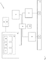
- Figure 1 a schematic block diagram of the automation arrangement as an embodiment of the invention.
- the Figure 1 shows an automation arrangement 1 as an embodiment of the invention.
- the automation arrangement 1 can be designed as a fully automated or a partially automated measuring system.
- the automation system 1 has an automation system 2, the automation system 2 having at least one actuator, such as an axis.
- the automation system 2 can for example have an industrial robot 3, which implements a handling method, a measuring method, a manufacturing method or the like.
- the automation system 2 has a measuring device 4, the measuring device 4 having sensors which implement a measuring task in the respective method.
- the measuring device 4 is designed in particular to record measurement data which describe the respective process, the respective workpiece or test piece.
- the measuring device 4 is designed in addition to the industrial robot 3, so that it is an additional measuring device 4.
- the automation arrangement 1 has a programmable logic controller 5, the programmable logic controller 5 implementing both a control function for the industrial robot 3 or more generally for the automation system 2 and also a log function for the respective method.
- the automation arrangement 1 has a measuring interface 6 which is connected and / or connectable to the measuring device 4 in terms of data technology.
- the measuring device 4 can transfer measured data via the measuring interface 6.
- the measurement interface 6 is in terms of data with the Programmable logic controller 5 connected, so that the measurement data can be forwarded to the programmable logic controller 5.
- the automation system 1 also has a control interface 7, the programmable logic controller 5 being able to transfer control commands to the automation system 2, in particular to the industrial robot 3, via the control interface 7.
- the control interface 7 is thus connected in terms of data technology to the automation system 2, in particular to the industrial robot 3.
- the control interface 7 is connected to the programmable logic controller 5 in terms of data.
- the communication between the programmable logic controller 5 and the measuring interface 6 and / or the control interface 7 takes place via a bus connection 8, the bus connection 8 being implemented by a Profibus.
- the programmable logic controller 5, the measuring interface 6 and the control interface 7 are connected to one another in the network via a switch.
- the communication between the measuring interface 6 and the measuring device 4 and / or the communication between the control interface 7 and the automation system 2, in particular the industrial robot 3 takes place via the bus connection 8 and / or the Profibus.
- the automation arrangement 1 has a display device 9, the display device 9 being connected for data purposes either via the bus connection 8 or directly with the programmable logic controller 5.
- the display device 9 forms a display for a user of the automation arrangement 1.
- the automation arrangement 1 has a memory 10, the memory 10 being connected in terms of data technology to the programmable controller 5 via the bus connection 8 or also via another data connection.
- the memory 10 can be designed as a volatile or non-volatile memory, for example the memory 10 is implemented as a hard disk or the like.
- the programmable logic controller 5 has a control module 11 for generating control commands for the automation system 2, in particular for the industrial robot 3.
- control commands for the automation system 2, in particular for the industrial robot 3.
- the at least one axis or the multiple axes of the automation system 2, in particular of the industrial robot 3, are controlled in real time during the process via the control commands.
- the programmable logic controller also has an evaluation module 12, the evaluation module 12 being designed to generate log data from measurement data from the measuring device 4, which are transmitted to the programmable logic controller 5 via the measurement interface 6.
- the log data are based on the measurement data and include the measurement data or data derived from the measurement data as log data.
- the programmable logic controller 5 optionally includes a storage module 13, the storage module 13 being designed to store the protocol data in the memory 10, preferably via the bus connection 8.
- the programmable logic controller 5 assumes a log function in addition to the usual control function for the automation system 2, in particular for the industrial robot 3, with log data on the ongoing process or method being generated in the automation system 2 and in the memory 10, in particular for documentation purposes , be filed.
- the log data can be stored in the form of a .qfd file, for example.
- the programmable logic controller also has a display module 14, the display module 14 being designed to transmit the log data as log display data to the display device 9, so that the log display data can be displayed in the display device 9.
- control module 11, the evaluation module 12, the storage module 13, the display module 14 are provided as library modules and / or PLC modules in a library 15 as usable modules.
- further functions can be provided in the library 15, those of the graphic processing and in particular the creation of the log display data.
- the library 15 is designed as part of the TIA Portal V14 SP1.
- the library 15 can be arranged in the programmable logic controller 5.
- an additional programming device 16 is provided, which is used to program the programmable logic controller 5 and which holds the library 15.
- the library 15 is arranged in the programmable logic controller 5 and the programmable logic controller 5 can be programmed, for example, via the display device 9, the display device 9 in this embodiment being a display and operating device.
- the display device 9 is designed as a panel with a touch function.
Landscapes
- Physics & Mathematics (AREA)
- General Physics & Mathematics (AREA)
- Engineering & Computer Science (AREA)
- Automation & Control Theory (AREA)
- Programmable Controllers (AREA)
Applications Claiming Priority (1)
| Application Number | Priority Date | Filing Date | Title |
|---|---|---|---|
| DE102019203921.9A DE102019203921A1 (de) | 2019-03-22 | 2019-03-22 | Automatisierungsanordnung, Verfahren zum Betrieb der Automatisierungsanordnung sowie Computerprogramm |
Publications (1)
| Publication Number | Publication Date |
|---|---|
| EP3712724A1 true EP3712724A1 (fr) | 2020-09-23 |
Family
ID=69941284
Family Applications (1)
| Application Number | Title | Priority Date | Filing Date |
|---|---|---|---|
| EP20164639.5A Withdrawn EP3712724A1 (fr) | 2019-03-22 | 2020-03-20 | Agencement d'automatisation, procédé de fonctionnement de l'agencement d'automatisation ainsi que programme informatique |
Country Status (3)
| Country | Link |
|---|---|
| EP (1) | EP3712724A1 (fr) |
| CN (1) | CN213634179U (fr) |
| DE (1) | DE102019203921A1 (fr) |
Families Citing this family (1)
| Publication number | Priority date | Publication date | Assignee | Title |
|---|---|---|---|---|
| DE102021123762A1 (de) | 2021-09-14 | 2023-03-16 | Pilz Gmbh & Co. Kg | Steuervorrichtung zur Maschinensteuerung und Sensordatenauswertung |
Citations (7)
| Publication number | Priority date | Publication date | Assignee | Title |
|---|---|---|---|---|
| DE29821111U1 (de) | 1998-11-25 | 1999-04-01 | Compaktbau-Flohr-Raumsysteme GmbH, 90556 Cadolzburg | Bauteilsatz zur Erstellung vorzugsweise mehrgeschossiger gebäudetechnisch vollausgestatteter Baukörper |
| US20080312883A1 (en) * | 2007-06-13 | 2008-12-18 | Festo Ag & Co | Method and Apparatus for Determining a Unique System Condition |
| US20080313228A1 (en) * | 2007-06-15 | 2008-12-18 | Rockwell Automation Technologies, Inc. | Controller log and log aggregation |
| US20160124413A1 (en) * | 2014-10-30 | 2016-05-05 | Lsis Co., Ltd. | Plc system and operating method thereof |
| WO2016080964A1 (fr) * | 2014-11-18 | 2016-05-26 | Siemens Aktiengesellschaft | Contextualisation sémantique dans un automate programmable |
| US20170017221A1 (en) * | 2015-07-16 | 2017-01-19 | Siemens Aktiengesellschaft | Knowledge-based programmable logic controller with flexible in-field knowledge management and analytics |
| WO2018035216A1 (fr) * | 2016-08-17 | 2018-02-22 | Siemens Corporation | Procédé et système de préservation de la confidentialité pour des services d'analyse de fabrication basés dans le nuage |
Family Cites Families (4)
| Publication number | Priority date | Publication date | Assignee | Title |
|---|---|---|---|---|
| DE29821118U1 (de) * | 1998-11-25 | 1999-02-11 | Siemens AG, 80333 München | Batterieüberwachungs- und Ladevorrichtung |
| AU2003900854A0 (en) * | 2003-02-26 | 2003-03-13 | Sesay, Sahid | General purpose electronic controller software |
| DE102006051102A1 (de) * | 2006-10-25 | 2008-04-30 | Endress + Hauser Gmbh + Co. Kg | Prozessautomatisierungssystem zur Bestimmung, zur Überwachung und/oder zum Beeinflussen von unterschiedlichen Prozessgröße und/oder Zustandsgrößen |
| GB2557354A (en) * | 2016-12-08 | 2018-06-20 | Whale Tankers Ltd | Telematics system |
-
2019
- 2019-03-22 DE DE102019203921.9A patent/DE102019203921A1/de active Pending
-
2020
- 2020-03-20 EP EP20164639.5A patent/EP3712724A1/fr not_active Withdrawn
- 2020-03-20 CN CN202020363577.XU patent/CN213634179U/zh active Active
Patent Citations (7)
| Publication number | Priority date | Publication date | Assignee | Title |
|---|---|---|---|---|
| DE29821111U1 (de) | 1998-11-25 | 1999-04-01 | Compaktbau-Flohr-Raumsysteme GmbH, 90556 Cadolzburg | Bauteilsatz zur Erstellung vorzugsweise mehrgeschossiger gebäudetechnisch vollausgestatteter Baukörper |
| US20080312883A1 (en) * | 2007-06-13 | 2008-12-18 | Festo Ag & Co | Method and Apparatus for Determining a Unique System Condition |
| US20080313228A1 (en) * | 2007-06-15 | 2008-12-18 | Rockwell Automation Technologies, Inc. | Controller log and log aggregation |
| US20160124413A1 (en) * | 2014-10-30 | 2016-05-05 | Lsis Co., Ltd. | Plc system and operating method thereof |
| WO2016080964A1 (fr) * | 2014-11-18 | 2016-05-26 | Siemens Aktiengesellschaft | Contextualisation sémantique dans un automate programmable |
| US20170017221A1 (en) * | 2015-07-16 | 2017-01-19 | Siemens Aktiengesellschaft | Knowledge-based programmable logic controller with flexible in-field knowledge management and analytics |
| WO2018035216A1 (fr) * | 2016-08-17 | 2018-02-22 | Siemens Corporation | Procédé et système de préservation de la confidentialité pour des services d'analyse de fabrication basés dans le nuage |
Non-Patent Citations (1)
| Title |
|---|
| ANONYMOUS: "List of filename extensions (M-R) - Wikipedia", 17 June 2020 (2020-06-17), XP055705719, Retrieved from the Internet <URL:https://en.wikipedia.org/wiki/List_of_filename_extensions_(M-R)> [retrieved on 20200617] * |
Also Published As
| Publication number | Publication date |
|---|---|
| DE102019203921A1 (de) | 2020-09-24 |
| CN213634179U (zh) | 2021-07-06 |
Similar Documents
| Publication | Publication Date | Title |
|---|---|---|
| DE102017011251B4 (de) | Robotersteuerung mit Funktion, die ein Lernen vereinfacht, und Robotersteuerverfahren | |
| DE102019110434B4 (de) | Werkzeugwahlvorrichtung und Maschinenlernvorrichtung | |
| DE102019006725B4 (de) | Steuereinrichtung und Steuersystem | |
| DE102011082291B4 (de) | Steuergerät für eine werkzeugmaschine und ein auf die zerspanung bezogenes datenverarbeitungssystem, welches mit selbiger ausgestattet ist | |
| DE102019208624A1 (de) | Steuervorrichtung zum einsatz an einer numerisch gesteuerten werkzeugmaschine und werkzeugmaschine mit einer steuervorrichtung | |
| EP2545417B1 (fr) | Procédé de remplacement d'un équipement de conduction existant dans un système d'automatisation par un nouvel équipement de conduction et système d'automatisation ainsi construit | |
| EP2796954B1 (fr) | Commande numérique avec information d'un système CAM lors du changement du programme de pièces | |
| EP2837981B1 (fr) | Procédé et dispositif de configuration automatisée d'une fonction de surveillance d'un robot industriel | |
| DE102015008575B4 (de) | Steuerungssystem, das eine Steuerungsvorrichtung zum Steuern einer Maschine mit mehreren Achsen umfasst | |
| DE112019007579T5 (de) | Numerische-Steuerung-Vorrichtung und Maschinelles-Lernen-Gerät | |
| EP3420426B1 (fr) | Dispositif et procede d'adaptation d'une commande numerique sur une machine a commander | |
| EP3969970B1 (fr) | Procédé de représentation et de commande de moyens de production, en particulier pour l'industrie de transformation des plastiques | |
| DE102017215508A1 (de) | Automatisierungssystem mit mindestens einem Feldgerät und mindestens einer Steuereinheit | |
| DE102005047466B3 (de) | Verfahren zur Optimierung des Bearbeitungsprozesses bei einer Maschine | |
| EP0553621A1 (fr) | Commande programmable par ordinateur pour une machine outil | |
| DE102017007909A1 (de) | Produktionssteuerung, ausgestattet mit einer Funktion zur Identifizierung der Ursache nach einem Betriebsstop einer Produktionseinrichtung, die Fertigungseinrichtungen umfasst | |
| DE102018007107A1 (de) | Steuereinrichtung und maschinenlerneinrichtung | |
| EP3712724A1 (fr) | Agencement d'automatisation, procédé de fonctionnement de l'agencement d'automatisation ainsi que programme informatique | |
| EP3456486A1 (fr) | Surveillance diversitaire anti-collision redondante | |
| DE102016117101A1 (de) | Verfahren zum Überwachen von zumindest einer Werkzeugmaschine und Fertigungsanlage | |
| EP3658996B1 (fr) | Procédé de fonctionnement d'une installation de production à commande numérique ainsi qu'installation de production correspondante | |
| DE102006059708B4 (de) | Antriebssteuerung für zumindest einen elektrischen Motor | |
| EP3504596B1 (fr) | Optimisation automatique du paramétrage de contrôleur de mouvement | |
| DE102017001171B4 (de) | Numerische Steuervorrichtung | |
| EP2026147A1 (fr) | Procédé destiné à la transmission de télégrammes entre un dispositif de commande et un périphérique via un appareil intermédiaire |
Legal Events
| Date | Code | Title | Description |
|---|---|---|---|
| PUAI | Public reference made under article 153(3) epc to a published international application that has entered the european phase |
Free format text: ORIGINAL CODE: 0009012 |
|
| STAA | Information on the status of an ep patent application or granted ep patent |
Free format text: STATUS: THE APPLICATION HAS BEEN PUBLISHED |
|
| AK | Designated contracting states |
Kind code of ref document: A1 Designated state(s): AL AT BE BG CH CY CZ DE DK EE ES FI FR GB GR HR HU IE IS IT LI LT LU LV MC MK MT NL NO PL PT RO RS SE SI SK SM TR |
|
| AX | Request for extension of the european patent |
Extension state: BA ME |
|
| STAA | Information on the status of an ep patent application or granted ep patent |
Free format text: STATUS: THE APPLICATION IS DEEMED TO BE WITHDRAWN |
|
| 18D | Application deemed to be withdrawn |
Effective date: 20210324 |