EP3712875A1 - Struktur eines ausfahrenden anzeigeschirms - Google Patents
Struktur eines ausfahrenden anzeigeschirms Download PDFInfo
- Publication number
- EP3712875A1 EP3712875A1 EP19894397.9A EP19894397A EP3712875A1 EP 3712875 A1 EP3712875 A1 EP 3712875A1 EP 19894397 A EP19894397 A EP 19894397A EP 3712875 A1 EP3712875 A1 EP 3712875A1
- Authority
- EP
- European Patent Office
- Prior art keywords
- rotating shaft
- frame strip
- hollow part
- side plate
- sides
- Prior art date
- Legal status (The legal status is an assumption and is not a legal conclusion. Google has not performed a legal analysis and makes no representation as to the accuracy of the status listed.)
- Granted
Links
Images




Classifications
-
- G—PHYSICS
- G09—EDUCATION; CRYPTOGRAPHY; DISPLAY; ADVERTISING; SEALS
- G09F—DISPLAYING; ADVERTISING; SIGNS; LABELS OR NAME-PLATES; SEALS
- G09F9/00—Indicating arrangements for variable information in which the information is built-up on a support by selection or combination of individual elements
- G09F9/30—Indicating arrangements for variable information in which the information is built-up on a support by selection or combination of individual elements in which the desired character or characters are formed by combining individual elements
- G09F9/301—Indicating arrangements for variable information in which the information is built-up on a support by selection or combination of individual elements in which the desired character or characters are formed by combining individual elements flexible foldable or roll-able electronic displays, e.g. thin LCD, OLED
-
- G—PHYSICS
- G06—COMPUTING OR CALCULATING; COUNTING
- G06F—ELECTRIC DIGITAL DATA PROCESSING
- G06F1/00—Details not covered by groups G06F3/00 - G06F13/00 and G06F21/00
- G06F1/16—Constructional details or arrangements
- G06F1/1613—Constructional details or arrangements for portable computers
- G06F1/1633—Constructional details or arrangements of portable computers not specific to the type of enclosures covered by groups G06F1/1615 - G06F1/1626
- G06F1/1656—Details related to functional adaptations of the enclosure, e.g. to provide protection against EMI, shock, water, or to host detachable peripherals like a mouse or removable expansions units like PCMCIA cards, or to provide access to internal components for maintenance or to removable storage supports like CDs or DVDs, or to mechanically mount accessories
-
- G—PHYSICS
- G06—COMPUTING OR CALCULATING; COUNTING
- G06F—ELECTRIC DIGITAL DATA PROCESSING
- G06F1/00—Details not covered by groups G06F3/00 - G06F13/00 and G06F21/00
- G06F1/16—Constructional details or arrangements
- G06F1/1613—Constructional details or arrangements for portable computers
- G06F1/1633—Constructional details or arrangements of portable computers not specific to the type of enclosures covered by groups G06F1/1615 - G06F1/1626
- G06F1/1675—Miscellaneous details related to the relative movement between the different enclosures or enclosure parts
- G06F1/1681—Details related solely to hinges
-
- G—PHYSICS
- G09—EDUCATION; CRYPTOGRAPHY; DISPLAY; ADVERTISING; SEALS
- G09F—DISPLAYING; ADVERTISING; SIGNS; LABELS OR NAME-PLATES; SEALS
- G09F9/00—Indicating arrangements for variable information in which the information is built-up on a support by selection or combination of individual elements
- G09F9/30—Indicating arrangements for variable information in which the information is built-up on a support by selection or combination of individual elements in which the desired character or characters are formed by combining individual elements
- G09F9/302—Indicating arrangements for variable information in which the information is built-up on a support by selection or combination of individual elements in which the desired character or characters are formed by combining individual elements characterised by the form or geometrical disposition of the individual elements
- G09F9/3026—Video wall, i.e. stackable semiconductor matrix display modules
-
- H—ELECTRICITY
- H05—ELECTRIC TECHNIQUES NOT OTHERWISE PROVIDED FOR
- H05K—PRINTED CIRCUITS; CASINGS OR CONSTRUCTIONAL DETAILS OF ELECTRIC APPARATUS; MANUFACTURE OF ASSEMBLAGES OF ELECTRICAL COMPONENTS
- H05K5/00—Casings, cabinets or drawers for electric apparatus
- H05K5/02—Details
- H05K5/0217—Mechanical details of casings
-
- G—PHYSICS
- G06—COMPUTING OR CALCULATING; COUNTING
- G06F—ELECTRIC DIGITAL DATA PROCESSING
- G06F1/00—Details not covered by groups G06F3/00 - G06F13/00 and G06F21/00
- G06F1/16—Constructional details or arrangements
- G06F1/1613—Constructional details or arrangements for portable computers
- G06F1/1615—Constructional details or arrangements for portable computers with several enclosures having relative motions, each enclosure supporting at least one I/O or computing function
- G06F1/1624—Constructional details or arrangements for portable computers with several enclosures having relative motions, each enclosure supporting at least one I/O or computing function with sliding enclosures, e.g. sliding keyboard or display
-
- G—PHYSICS
- G06—COMPUTING OR CALCULATING; COUNTING
- G06F—ELECTRIC DIGITAL DATA PROCESSING
- G06F1/00—Details not covered by groups G06F3/00 - G06F13/00 and G06F21/00
- G06F1/16—Constructional details or arrangements
- G06F1/1613—Constructional details or arrangements for portable computers
- G06F1/1633—Constructional details or arrangements of portable computers not specific to the type of enclosures covered by groups G06F1/1615 - G06F1/1626
- G06F1/1637—Details related to the display arrangement, including those related to the mounting of the display in the housing
- G06F1/1652—Details related to the display arrangement, including those related to the mounting of the display in the housing the display being flexible, e.g. mimicking a sheet of paper, or rollable
-
- G—PHYSICS
- G06—COMPUTING OR CALCULATING; COUNTING
- G06F—ELECTRIC DIGITAL DATA PROCESSING
- G06F2203/00—Indexing scheme relating to G06F3/00 - G06F3/048
- G06F2203/041—Indexing scheme relating to G06F3/041 - G06F3/045
- G06F2203/04102—Flexible digitiser, i.e. constructional details for allowing the whole digitising part of a device to be flexed or rolled like a sheet of paper
Definitions
- the invention relates to a rollable display screen structure, in particular to a technical means for driving a rotating shaft to move by a transversely movable driving component to unroll and roll up a flexible screen.
- the above reference shows different design techniques regarding the structure and application of the conventional display screen apparatus.
- gaps between the monitors (or display screens) are unavoidable when combining a plurality of monitors (or display screens) into a larger screen (or television wall), and these crisscross gaps not only influence the integrity of the display of the larger screen (or television wall), but also are easy to cause visual fatigue of viewers, resulting in a defect in this application.
- the present invention was developed by the inventor as an improvement to the prior art.
- It's another object of the invention to provide a rollable display screen structure wherein the rollable display screen structure is provided with a main base capable of accommodating the driving component, hollow parts are provided on at least one side of the main base, respectively, and guiding components are provided on upper and lower sides of a corresponding hollow part, respectively, for guiding the driving component to unroll and roll up; wings are provided on upper and lower sides of the hollow part, respectively, outside the main base, and when the wing is rolled up inwards, the wing can just shield the hollow part to protect the components in the main base; when the wing is unrolled outwards, a guiding runner can be preset to guide the movement of the rotating shaft, so that the flexible screen can be unrolled stably in an expected direction.
- each of the wings forms a positioning part at one end distal to the main base with respect to the guiding runner, and each of the positioning parts can extend to both outer sides of the main base when each of the wings is unrolled outwards, so that after the flexible screen is fully unrolled, the rotating shaft can extend into the positioning part while leaving an elastic biasing space with a front side (or rear side) of the main base, without contacting the main base improperly, moreover, an outer side of the driving component generates an elastic biasing force on the rotating shaft to pull the flexible screen properly under tension, so that wrinkles due to loosening of the flexible screen can be effectively eliminated.
- the technical solution implemented by the present invention comprises: a hollow main base, at least one driving component, and a flexible screen, wherein the hollow main base is provided with at least one hollow part which opens to the outside, and guiding components are symmetrically provided in the main base along two sides of the hollow part, respectively; the at least one driving component is provided in the main base, and the driving component can move along the guiding component to extend out of the main base; the flexible screen is wound around an outer periphery of at least one rotating shaft, the rotating shaft is rotatably disposed on the driving component, can move out of a side of the main base preferentially and form linkage, and when the driving component, in linkage with the rotating shaft, moves to the outside of the main base along the guiding component, the flexible screen can be gradually released and unrolled outwards from the outer periphery of the rotating shaft.
- the driving component is provided with a power source, and the power source can drive the driving component to move along the guiding component.
- the main base is provided with two opposite first and second hollow parts, two forward guiding components are symmetrically arranged in the main base along two sides of the first hollow part, and two backward guiding components extending in a reverse direction to the forward guiding components are symmetrically arranged in the main base along two sides of the second hollow part;
- the two driving components are provided in the main base, each of the driving components is provided with a power source that drives the driving component to move along the forward or backward guiding component, respectively;
- two sides of the flexible screen are respectively wound around the outer peripheries of the first rotating shaft and the second rotating shaft, the first rotating shaft and the second rotating shaft are rotatably arranged, respectively, on sides of the two driving components to form linkage, and when the two driving components, in linkage with the first rotating shaft and the second rotating shaft respectively, move out of the main base along the forward guiding component and the backward guiding component, the flexible screen can be gradually released from the peripheries of the first rotating shaft and the second rotating shaft to be unrolled outwards.
- the main base is provided pivotably with first side wings on two sides of the first hollow part, respectively, the two first side wings can be turned inwards to cover the first hollow part, and can be turned outwards to open the first hollow part; moreover, second side wings are provided pivotably on two sides of the second hollow part, respectively, the two second side wings can be turned inwards to cover the second hollow part, and can be turned outwards to open the second hollow part.
- the two first side wings are respectively provided with a first side guiding runner engaged with the forward guiding component on a side surface facing the first hollow part when rolled up, and the first side guiding runners can form sliding guide to engage the forward guiding component on two ends of the first rotating shaft when the first side wings horizontally extend outwards;
- the two second side wings are respectively provided with a second side guiding runner engaged with the backward guiding component on a side surface facing the second hollow part when rolled up, and the second side guiding runners can form sliding guide to engage the backward guiding component on two ends of the second rotating shaft when the second side wings horizontally extend outwards.
- a positioning part with a biasing space is formed on the first guiding runner and the second guiding runner, respectively, at an end distal to the main base, and the positioning parts protrude out of a front side or a rear side of the main base with ends aligned.
- each of the driving components is respectively provided with a set of linkage components driven by the power source, and each set of linkage components is respectively connected to the forward guiding component and the backward guiding component.
- the forward guiding component and the backward guiding component are forward and backward racks arranged in opposite directions
- the power sources are motors
- the linkage components are output gears driven by the motors and meshed with the forward and backward racks, respectively.
- the two driving components are respectively provided with two parallel main holders
- the first rotating shaft and the second rotating shaft are respectively provided pivotably with a rotating shaft holder proximate to two ends
- the rotating shaft holder of the first rotating shaft is pivotably connected with the two main holders of one of the driving components
- the rotating shaft holder of the second rotating shaft is pivotably connected with the two main holders of the other driving component
- each of the rotating shaft holders has pivot elasticity relative to the main holders pivotably connected therewith, so that the rotating shaft holders of the first rotating shaft and the second rotating shaft generate tensile elasticity on two sides of the flexible screen, respectively, thereby ensuring that the flexible screen can maintain a tensioned and flattened state after being completely unrolled.
- the main base is provided with two parallel first and two frame strips, a first side plate and a second side plate are attached to two sides of the first frame strip and the second frame strip, respectively, so that a hollow accommodating space is enclosed by the first frame strip, the second frame strip, the first side plate and the second side plate, and the first hollow part and the second hollow part are respectively formed on two sides of the accommodating space between the first frame strip and the second frame strip.
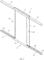
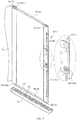
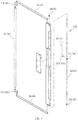
- the main structure of the present invention includes: a main base 1, two driving components 2 and 4 and a flexible screen 3; the main base 1 is provided with a first frame strip 11 and a second frame strip 12 which are parallel, a first side plate 13 and a second side plate 14 are attached to two sides of the first frame strip 11 and the second frame strip 12, respectively, so that a hollow accommodating space is enclosed by the first frame strip 11, the second frame strip 12, the first side plate 13 and the second side plate 14, and a first hollow part 101 and a second hollow part 102 which open outwards are respectively formed towards two sides of the accommodating space between the first frame strip 11 and the second frame strip 12.
- a forward guiding component 111 (which can be a forward rack) and a backward guiding component 112 (which can be a backward rack) extending in a reverse direction to the forward guiding component 111 are provided in the first frame strip 11, a first side wing 15 and a second side wing 16 are respectively pivotably provided at two ends of the first frame strip 11, and a first side guiding runner 151 and a second side guiding runner 161 are provided on each of the first side wing 15 and second side wing 16 to engage sides of the forward guiding component 111 and the backward guiding component 112, respectively; and a forward guiding component 121 and a backward component 122 (which can be respectively a forward rack and a backward rack) corresponding to the forward guiding component 111 and the backward component 112 are provided in the second frame strip 12, respectively, a first side wing 17 and a second side wing 18 are respectively pivotably provided at two ends of the second frame strip 12, and a first side guiding runner 171 and a second side
- bent positioning parts 152, 172, 162 and 182 are formed on the first and second side guiding runners 151, 171, 161 and 181, correspondingly, at ends distal to the first frame strip 11 and the second frame strip 12, and the positioning parts 152, 172, 162 and 182 protrude out of a front (or a rear) side of the first side plate 13 (or the second side plate 14) with ends aligned.
- the driving components 2 and 4 have the same structure and are arranged in the main base 1 in opposite directions, the driving components 2 and 4 are provided with power sources 21 and 41, driving components 22 and 42 driven by the power sources 21 and 41, and linkage components 23 and 43 driven by the driving components 22 and 42, respectively, and the linkage components 23 and 43 are connected to the forward guiding components 111 and 121 and the backward guiding components 112 and 122, respectively; and main holders 24 and 25 and main holders 44 and 45 are pivotably connected at sides of the two driving components 2 and 4, respectively, and extend in opposite directions.
- the power sources 21 and 41 may be motors having driving gears 211 and 411, respectively, for outputting power
- the driving components 22 and 42 are shafts having linkage gears 221 and 421 in the middle of each shaft for meshing with the driving gears 211 and 411
- the linkage components 23 and 43 are output gears provided at both ends of each of the shafts
- the two linkage components 23 (output gears) are engaged with the two forward guiding components 111 and 121 (forward racks), respectively
- the two linkage components 43 (output gears) are engaged with the backward guiding components 112 and 122 (output gears), respectively
- the power sources 21 and 41 (motors) are used for driving the driving components 22 and 42 (shafts) to rotate through the driving gears 211 and 411 and the linkage gears 221 and 421, and the linkage components 23 and 43 (output gears) can be driven to rotate on the forward guiding components 111 and 121 (forward racks) and the backward guiding components 112
- the flexible screen 3 passes through an outer side of the first side plate 13 (or the second side plate 14) in the middle section, two sides of the flexible screen 3 are respectively wound around the outer peripheries of a first rotating shaft 31 and a second rotating shaft 32, and the first rotating shaft 31 and the second rotating shaft 32 are respectively arranged in the main base 1 proximate the sides of the first hollow part 101 and the second hollow part 102; two ends of the first rotating shaft 31 extend to sides of the first side guiding runners 151 and 171 of the first side wings 15 and 17, respectively, parts close to the two ends of the first rotating shaft 31 are respectively provided pivotably at an end of rotating shaft holders 311 and 312, the other end of the two rotating shaft holders 311 and 312 is provided pivotably at ends of the two main holders 24 and 25, respectively, and the two rotating shaft holders 311 and 312 have pivot elasticity relative to the two main holders 24 and 25 pivotably connected therewith, so that the two rotating shaft holders 311 and 312 can generate tensile elasticity on one side of the flexible screen 3; two ends
- the driving components 2 and 4 are accommodated in the accommodating space of the main base 1, and the two first wings 15 and 17 are attached to the outside of the first hollow part 101, and the two second wings 16 and 18 are attached to the outside of the second hollow part 102 (as shown in FIG. 5 ), so that the rolled up structure has the minimum overall volume.
- the first side wings 15, 17, 16 and 18 can be pivoted outwards by 90 degrees, so that the first side guiding runners 151 and 171 are respectively engaged with the forward guiding components 111 and 121; the second side guiding runners 161 and 181 engage (as shown in FIGS. 6 and 7 ) the backward guiding components 112 and 122, respectively.
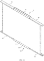
- the two driving components 2 and 4 respectively drive the linkage components 23 and 43 (output gears) to move by the power sources 21 and 41 (motors) through the driving components 22 and 42, so that the driving component 2 can slide along the two forward guiding components 111 and 121, and simultaneously the two ends of the first rotating shaft 31 are driven to move outwards along the first side guiding runners 151 and 171, the driving component 4 can slide along the two backward guiding components 112 and 122, the two ends of the second rotating shaft 32 are driven to move outwards along the second side guiding runners 161 and 181, and the two sides of the flexible screen 3 can be gradually unrolled along with the outward movement of the first rotating shaft 31 and the second rotating shaft 32 (as shown in FIGS. 8 and 9 ).
- the two ends of the first rotating shaft 31 can be respectively bent and embedded into the two positioning parts 152 and 172 from the two first side guiding runners 151 and 171; the two ends of the second rotating shaft 32 can be respectively bent and embedded into the two positioning parts 162 and 182 from the two second side guiding runners 161 and 181, and reverse tensile elasticity can be generated on the two sides of the flexible screen 3 by the rotating shaft holders 311 and 312 and the rotating shaft holders 321 and 322.
- the two sides of the flexible screen 3 can be fully unrolled and kept in a tensioned and flattened state, and a gap (shown in FIGS. 10 and 111) exists between the fully unrolled flexible screen 3 and an outer surface side of the first side plate 13 (or the second side plate 14) to prevent the outer surface side of the first side plate 13 (or the second side plate 14) from contacting the flexible screen 3 and causing wrinkles.
- a volute spring (not shown) can be provided between the first rotating shaft 31 and the second rotating shaft 32 and the rotating shaft holders 311, 312, 321 and 322 as required, respectively, and when the first rotating shaft 31 and the second rotating shaft 32 drive the two sides of the flexible screen 3 to be gradually unrolled outwards, each volute spring is in a compressed state; when the first rotating shaft 31 and the second rotating shaft 32 move inwards and closer to each other, the first rotating shaft 31 and the second rotating shaft 32 can reversely rotate by utilizing the spring-back elasticity of each volute spring, whereby the flexible screen 3 is rolled back to the original rolled up state.
- the driving component 4 (or the driving component 2) and the second rotating shaft 32 (or the first rotating shaft 31) can be directly omitted, and the side of the flexible screen 3 distal to the first rotating shaft 31 (or the second rotating shaft 32) is positioned in the main base 1 at a part proximate to the second hollow part 102 (or the first hollow part 101), the first rotating shaft 31 (or the second rotating shaft 32) is driven to move outwards by the driving component 2 (or the driving component 4) alone, and a similar effect of unrolling the flexible screen 3 can be achieved.
- the rollable display screen structure of the present invention is different from the prior art, and can produce a relatively integral display effect through a relatively simple action, featuring indeed novelty and progress as an invention, and thus an application for an invention patent is submitted according to law; the above description is only the preferred embodiment of the invention, and alternations, modifications, changes or equivalent substitutions without departing the spirit and scope of the invention shall fall within the scope of the appended claims.
Landscapes
- Engineering & Computer Science (AREA)
- Theoretical Computer Science (AREA)
- Physics & Mathematics (AREA)
- Computer Hardware Design (AREA)
- General Physics & Mathematics (AREA)
- General Engineering & Computer Science (AREA)
- Human Computer Interaction (AREA)
- Mathematical Physics (AREA)
- Microelectronics & Electronic Packaging (AREA)
- Multimedia (AREA)
- Devices For Indicating Variable Information By Combining Individual Elements (AREA)
- Transmission Devices (AREA)
- Fittings On The Vehicle Exterior For Carrying Loads, And Devices For Holding Or Mounting Articles (AREA)
- Overhead Projectors And Projection Screens (AREA)
Applications Claiming Priority (1)
| Application Number | Priority Date | Filing Date | Title |
|---|---|---|---|
| PCT/CN2019/071286 WO2020143015A1 (zh) | 2019-01-11 | 2019-01-11 | 延展式显示屏幕之结构 |
Publications (4)
| Publication Number | Publication Date |
|---|---|
| EP3712875A1 true EP3712875A1 (de) | 2020-09-23 |
| EP3712875A4 EP3712875A4 (de) | 2021-08-25 |
| EP3712875B1 EP3712875B1 (de) | 2023-09-13 |
| EP3712875C0 EP3712875C0 (de) | 2023-09-13 |
Family
ID=71520739
Family Applications (1)
| Application Number | Title | Priority Date | Filing Date |
|---|---|---|---|
| EP19894397.9A Active EP3712875B1 (de) | 2019-01-11 | 2019-01-11 | Struktur eines ausfahrenden anzeigeschirms |
Country Status (6)
| Country | Link |
|---|---|
| US (1) | US11212927B2 (de) |
| EP (1) | EP3712875B1 (de) |
| JP (1) | JP6965454B2 (de) |
| KR (1) | KR102435781B1 (de) |
| CN (1) | CN111684509B (de) |
| WO (1) | WO2020143015A1 (de) |
Families Citing this family (13)
| Publication number | Priority date | Publication date | Assignee | Title |
|---|---|---|---|---|
| US12189426B2 (en) * | 2019-04-10 | 2025-01-07 | Lg Electronics Inc. | Flexible display apparatus |
| CN112769982B (zh) * | 2020-11-17 | 2023-04-07 | Oppo广东移动通信有限公司 | 电子装置 |
| WO2022114892A1 (ko) | 2020-11-30 | 2022-06-02 | 삼성전자주식회사 | 다 방향 확장 장치 및 방법 |
| CN113339632A (zh) * | 2021-03-30 | 2021-09-03 | 广州纪光新媒体系统有限公司 | 文化轨道展示系统及方法 |
| US12524043B2 (en) * | 2021-05-12 | 2026-01-13 | Hewlett-Packard Development Company, L.P. | Expandable display panels |
| CN113259511B (zh) * | 2021-05-14 | 2024-03-29 | 维沃移动通信有限公司 | 电子设备 |
| CN115529365A (zh) | 2021-06-25 | 2022-12-27 | 北京小米移动软件有限公司 | 一种驱动机构及电子设备 |
| KR20230024119A (ko) | 2021-08-11 | 2023-02-20 | 삼성전자주식회사 | 플렉서블 디스플레이를 포함하는 전자 장치 및 그 동작 방법 |
| KR20230043303A (ko) * | 2021-09-23 | 2023-03-31 | 삼성디스플레이 주식회사 | 표시장치 |
| CN114244930B (zh) * | 2021-12-17 | 2024-08-06 | 维沃移动通信有限公司 | 电子设备 |
| CN116066672B (zh) * | 2022-12-29 | 2024-09-13 | 创维集团智能科技有限公司 | 显示设备 |
| WO2025105979A1 (ru) * | 2023-11-16 | 2025-05-22 | Публичное Акционерное Общество "Сбербанк России" | Гибкое мультимедийное устройство |
| CN118475054B (zh) * | 2024-07-09 | 2024-09-24 | 南京睿目电子科技有限公司 | 一种便于维护的led屏幕可拆卸安装边框 |
Family Cites Families (34)
| Publication number | Priority date | Publication date | Assignee | Title |
|---|---|---|---|---|
| WO2004114259A2 (en) * | 2003-06-23 | 2004-12-29 | Simon Richard Daniel | Display device having an extendible screen |
| US7440265B2 (en) * | 2005-12-27 | 2008-10-21 | Lite-On Technology Corporation | Variable-sized screen |
| US8379377B2 (en) | 2010-01-20 | 2013-02-19 | Creator Technology B.V. | Electronic device with at least one extendable display section |
| KR101273182B1 (ko) * | 2011-02-18 | 2013-06-17 | 주식회사 팬택 | 연성 디스플레이 장치 및 이를 이용한 이동통신 단말기 |
| TWI582640B (zh) * | 2013-01-10 | 2017-05-11 | 黃海濤 | 具可捲式螢幕的掌上型電子裝置及其顯示方法 |
| KR101636753B1 (ko) * | 2013-04-08 | 2016-07-11 | 서준 | 접이식 전자통신 기기 |
| TWI608328B (zh) * | 2013-10-24 | 2017-12-11 | 緯創資通股份有限公司 | 電子裝置 |
| US9727295B2 (en) * | 2013-12-17 | 2017-08-08 | Lenovo (Singapore) Pte. Ltd. | Extendable display mechanism |
| CN203689284U (zh) * | 2014-01-08 | 2014-07-02 | 刘丽 | 简易开盖关闭的电脑机箱 |
| KR102358935B1 (ko) * | 2014-02-12 | 2022-02-04 | 가부시키가이샤 한도오따이 에네루기 켄큐쇼 | 전자 기기 |
| KR102329953B1 (ko) | 2014-12-03 | 2021-11-25 | 삼성디스플레이 주식회사 | 롤러블 표시 장치 |
| KR102252322B1 (ko) * | 2015-04-30 | 2021-05-14 | 삼성전자주식회사 | 롤러블 디스플레이 장치 |
| US9772657B2 (en) | 2015-04-30 | 2017-09-26 | Samsung Electronics Co., Ltd. | Rollable display device |
| CN104882078B (zh) * | 2015-06-25 | 2018-01-05 | 京东方科技集团股份有限公司 | 一种柔性显示装置 |
| KR101792692B1 (ko) | 2015-08-28 | 2017-11-01 | 이유구 | 롤러블 디스플레이를 갖는 휴대용 단말기 |
| US10488959B2 (en) * | 2015-11-04 | 2019-11-26 | Dell Products L.P. | Flexible roll-up information handling system |
| KR20170055865A (ko) | 2015-11-12 | 2017-05-22 | 엘지전자 주식회사 | 롤러블 이동 단말기 및 그것의 제어방법 |
| KR102534580B1 (ko) * | 2016-07-27 | 2023-05-19 | 삼성디스플레이 주식회사 | 표시 장치 |
| KR102627801B1 (ko) * | 2016-10-10 | 2024-01-22 | 삼성디스플레이 주식회사 | 확장형 표시 장치 |
| CN206301242U (zh) | 2016-10-27 | 2017-07-04 | 珠海市魅族科技有限公司 | 显示组件及移动终端 |
| KR101735470B1 (ko) | 2016-11-23 | 2017-05-15 | 주식회사 지엔티시스템즈 | 디스플레이의 벤딩 및 롤링 시연장치 |
| CN106713554A (zh) * | 2017-02-23 | 2017-05-24 | 维沃移动通信有限公司 | 一种显示屏组件和移动终端 |
| CN206557661U (zh) * | 2017-02-28 | 2017-10-13 | 宇龙计算机通信科技(深圳)有限公司 | 屏幕可伸缩的终端 |
| CN107424517B (zh) | 2017-05-24 | 2019-10-29 | 黎德智 | 一种可收展的柔性显示器 |
| CN109085880A (zh) * | 2017-06-13 | 2018-12-25 | 林锦浩 | 一种活页式屏幕遮光罩 |
| CN207529588U (zh) * | 2017-09-22 | 2018-06-22 | 昆山国显光电有限公司 | 卷轴式显示器 |
| KR102389189B1 (ko) * | 2017-11-29 | 2022-04-22 | 삼성전자주식회사 | 확장가능한 디스플레이 영역을 갖는 플렉시블 디스플레이를 구비한 전자 장치 |
| WO2019109261A1 (zh) * | 2017-12-06 | 2019-06-13 | 朱卫 | 一种用于扩展显示器的传动装置 |
| CN108600442B (zh) * | 2018-04-12 | 2019-09-13 | Oppo广东移动通信有限公司 | 插卡装置及电子设备 |
| CN109062334B (zh) * | 2018-07-27 | 2020-11-03 | 上海天马微电子有限公司 | 显示装置 |
| CN108974321A (zh) * | 2018-08-30 | 2018-12-11 | 长光卫星技术有限公司 | 一种塞拉式舱门 |
| KR102609502B1 (ko) * | 2018-10-30 | 2023-12-04 | 삼성디스플레이 주식회사 | 표시 장치 |
| CN209418055U (zh) | 2019-01-11 | 2019-09-20 | 江阴康瑞成型技术科技有限公司 | 延展式显示屏幕之结构 |
| CN111835893A (zh) * | 2019-04-22 | 2020-10-27 | 北京小米移动软件有限公司 | 终端以及伸缩机械部件 |
-
2019
- 2019-01-11 EP EP19894397.9A patent/EP3712875B1/de active Active
- 2019-01-11 KR KR1020207017784A patent/KR102435781B1/ko active Active
- 2019-01-11 CN CN201980000050.0A patent/CN111684509B/zh active Active
- 2019-01-11 JP JP2020535558A patent/JP6965454B2/ja active Active
- 2019-01-11 WO PCT/CN2019/071286 patent/WO2020143015A1/zh not_active Ceased
- 2019-01-11 US US16/772,836 patent/US11212927B2/en active Active
Also Published As
| Publication number | Publication date |
|---|---|
| JP6965454B2 (ja) | 2021-11-10 |
| JP2021513669A (ja) | 2021-05-27 |
| CN111684509B (zh) | 2022-01-07 |
| WO2020143015A1 (zh) | 2020-07-16 |
| CN111684509A (zh) | 2020-09-18 |
| KR102435781B1 (ko) | 2022-08-25 |
| EP3712875B1 (de) | 2023-09-13 |
| KR20200096548A (ko) | 2020-08-12 |
| EP3712875C0 (de) | 2023-09-13 |
| US11212927B2 (en) | 2021-12-28 |
| US20210227708A1 (en) | 2021-07-22 |
| EP3712875A4 (de) | 2021-08-25 |
Similar Documents
| Publication | Publication Date | Title |
|---|---|---|
| EP3712875A1 (de) | Struktur eines ausfahrenden anzeigeschirms | |
| CN113037892B (zh) | 电子设备 | |
| US11966258B2 (en) | Terminal provided with flexible screen | |
| US11315447B2 (en) | Display device | |
| US20220317736A1 (en) | Flexible display screen assembly and electronic device | |
| US10045448B2 (en) | Flexible screen module and electronic device having the module | |
| CN114900572B (zh) | 壳体组件及电子设备 | |
| KR102421579B1 (ko) | 폴더블 표시 장치 | |
| CN113345332A (zh) | 柔性显示装置 | |
| CN110738931B (zh) | 卷曲装置及柔性屏展示设备 | |
| US11526198B1 (en) | Rollable displays with tension controls | |
| CN111462633B (zh) | 一种可卷曲柔性屏的展平结构和显示装置 | |
| CN113099015A (zh) | 电子设备 | |
| WO2021238986A1 (zh) | 电子设备 | |
| KR20230074821A (ko) | 표시 모듈 및 표시 장치 | |
| WO2023125645A1 (zh) | 电子设备 | |
| WO2024160060A1 (zh) | 一种滑卷装置及显示装置 | |
| WO2023109840A1 (zh) | 电子设备 | |
| CN115762341B (zh) | 显示装置 | |
| CN215868447U (zh) | 一种电子设备 | |
| TWI693504B (zh) | 延展式顯示屏幕之結構 | |
| CN114708801A (zh) | 可卷曲显示装置 | |
| TWM578814U (zh) | Structure of the extended display screen | |
| Han et al. | P‐8.3: Novel Rolling Hinge for Rollable Mobile Device | |
| US20230350461A1 (en) | Rollable display device |
Legal Events
| Date | Code | Title | Description |
|---|---|---|---|
| STAA | Information on the status of an ep patent application or granted ep patent |
Free format text: STATUS: UNKNOWN |
|
| STAA | Information on the status of an ep patent application or granted ep patent |
Free format text: STATUS: THE INTERNATIONAL PUBLICATION HAS BEEN MADE |
|
| PUAI | Public reference made under article 153(3) epc to a published international application that has entered the european phase |
Free format text: ORIGINAL CODE: 0009012 |
|
| STAA | Information on the status of an ep patent application or granted ep patent |
Free format text: STATUS: REQUEST FOR EXAMINATION WAS MADE |
|
| 17P | Request for examination filed |
Effective date: 20200618 |
|
| AK | Designated contracting states |
Kind code of ref document: A1 Designated state(s): AL AT BE BG CH CY CZ DE DK EE ES FI FR GB GR HR HU IE IS IT LI LT LU LV MC MK MT NL NO PL PT RO RS SE SI SK SM TR |
|
| AX | Request for extension of the european patent |
Extension state: BA ME |
|
| A4 | Supplementary search report drawn up and despatched |
Effective date: 20210723 |
|
| RIC1 | Information provided on ipc code assigned before grant |
Ipc: G09F 9/30 20060101AFI20210719BHEP Ipc: G06F 1/16 20060101ALI20210719BHEP |
|
| RAP3 | Party data changed (applicant data changed or rights of an application transferred) |
Owner name: JIANGSU KANGRUI NEW MATERIAL TECHNOLOGY CO., LTD. |
|
| DAV | Request for validation of the european patent (deleted) | ||
| DAX | Request for extension of the european patent (deleted) | ||
| STAA | Information on the status of an ep patent application or granted ep patent |
Free format text: STATUS: EXAMINATION IS IN PROGRESS |
|
| 17Q | First examination report despatched |
Effective date: 20221130 |
|
| GRAP | Despatch of communication of intention to grant a patent |
Free format text: ORIGINAL CODE: EPIDOSNIGR1 |
|
| STAA | Information on the status of an ep patent application or granted ep patent |
Free format text: STATUS: GRANT OF PATENT IS INTENDED |
|
| INTG | Intention to grant announced |
Effective date: 20230414 |
|
| GRAS | Grant fee paid |
Free format text: ORIGINAL CODE: EPIDOSNIGR3 |
|
| GRAA | (expected) grant |
Free format text: ORIGINAL CODE: 0009210 |
|
| STAA | Information on the status of an ep patent application or granted ep patent |
Free format text: STATUS: THE PATENT HAS BEEN GRANTED |
|
| AK | Designated contracting states |
Kind code of ref document: B1 Designated state(s): AL AT BE BG CH CY CZ DE DK EE ES FI FR GB GR HR HU IE IS IT LI LT LU LV MC MK MT NL NO PL PT RO RS SE SI SK SM TR |
|
| REG | Reference to a national code |
Ref country code: CH Ref legal event code: EP |
|
| REG | Reference to a national code |
Ref country code: DE Ref legal event code: R096 Ref document number: 602019037633 Country of ref document: DE |
|
| REG | Reference to a national code |
Ref country code: IE Ref legal event code: FG4D |
|
| U01 | Request for unitary effect filed |
Effective date: 20230913 |
|
| U07 | Unitary effect registered |
Designated state(s): AT BE BG DE DK EE FI FR IT LT LU LV MT NL PT SE SI Effective date: 20230919 |
|
| PG25 | Lapsed in a contracting state [announced via postgrant information from national office to epo] |
Ref country code: GR Free format text: LAPSE BECAUSE OF FAILURE TO SUBMIT A TRANSLATION OF THE DESCRIPTION OR TO PAY THE FEE WITHIN THE PRESCRIBED TIME-LIMIT Effective date: 20231214 |
|
| PG25 | Lapsed in a contracting state [announced via postgrant information from national office to epo] |
Ref country code: RS Free format text: LAPSE BECAUSE OF FAILURE TO SUBMIT A TRANSLATION OF THE DESCRIPTION OR TO PAY THE FEE WITHIN THE PRESCRIBED TIME-LIMIT Effective date: 20230913 Ref country code: NO Free format text: LAPSE BECAUSE OF FAILURE TO SUBMIT A TRANSLATION OF THE DESCRIPTION OR TO PAY THE FEE WITHIN THE PRESCRIBED TIME-LIMIT Effective date: 20231213 Ref country code: HR Free format text: LAPSE BECAUSE OF FAILURE TO SUBMIT A TRANSLATION OF THE DESCRIPTION OR TO PAY THE FEE WITHIN THE PRESCRIBED TIME-LIMIT Effective date: 20230913 Ref country code: GR Free format text: LAPSE BECAUSE OF FAILURE TO SUBMIT A TRANSLATION OF THE DESCRIPTION OR TO PAY THE FEE WITHIN THE PRESCRIBED TIME-LIMIT Effective date: 20231214 |
|
| U20 | Renewal fee for the european patent with unitary effect paid |
Year of fee payment: 6 Effective date: 20240125 |
|
| PG25 | Lapsed in a contracting state [announced via postgrant information from national office to epo] |
Ref country code: IS Free format text: LAPSE BECAUSE OF FAILURE TO SUBMIT A TRANSLATION OF THE DESCRIPTION OR TO PAY THE FEE WITHIN THE PRESCRIBED TIME-LIMIT Effective date: 20240113 |
|
| PG25 | Lapsed in a contracting state [announced via postgrant information from national office to epo] |
Ref country code: ES Free format text: LAPSE BECAUSE OF FAILURE TO SUBMIT A TRANSLATION OF THE DESCRIPTION OR TO PAY THE FEE WITHIN THE PRESCRIBED TIME-LIMIT Effective date: 20230913 |
|
| PG25 | Lapsed in a contracting state [announced via postgrant information from national office to epo] |
Ref country code: SM Free format text: LAPSE BECAUSE OF FAILURE TO SUBMIT A TRANSLATION OF THE DESCRIPTION OR TO PAY THE FEE WITHIN THE PRESCRIBED TIME-LIMIT Effective date: 20230913 Ref country code: RO Free format text: LAPSE BECAUSE OF FAILURE TO SUBMIT A TRANSLATION OF THE DESCRIPTION OR TO PAY THE FEE WITHIN THE PRESCRIBED TIME-LIMIT Effective date: 20230913 Ref country code: IS Free format text: LAPSE BECAUSE OF FAILURE TO SUBMIT A TRANSLATION OF THE DESCRIPTION OR TO PAY THE FEE WITHIN THE PRESCRIBED TIME-LIMIT Effective date: 20240113 Ref country code: ES Free format text: LAPSE BECAUSE OF FAILURE TO SUBMIT A TRANSLATION OF THE DESCRIPTION OR TO PAY THE FEE WITHIN THE PRESCRIBED TIME-LIMIT Effective date: 20230913 Ref country code: CZ Free format text: LAPSE BECAUSE OF FAILURE TO SUBMIT A TRANSLATION OF THE DESCRIPTION OR TO PAY THE FEE WITHIN THE PRESCRIBED TIME-LIMIT Effective date: 20230913 Ref country code: SK Free format text: LAPSE BECAUSE OF FAILURE TO SUBMIT A TRANSLATION OF THE DESCRIPTION OR TO PAY THE FEE WITHIN THE PRESCRIBED TIME-LIMIT Effective date: 20230913 |
|
| PG25 | Lapsed in a contracting state [announced via postgrant information from national office to epo] |
Ref country code: PL Free format text: LAPSE BECAUSE OF FAILURE TO SUBMIT A TRANSLATION OF THE DESCRIPTION OR TO PAY THE FEE WITHIN THE PRESCRIBED TIME-LIMIT Effective date: 20230913 |
|
| REG | Reference to a national code |
Ref country code: DE Ref legal event code: R097 Ref document number: 602019037633 Country of ref document: DE |
|
| PLBE | No opposition filed within time limit |
Free format text: ORIGINAL CODE: 0009261 |
|
| STAA | Information on the status of an ep patent application or granted ep patent |
Free format text: STATUS: NO OPPOSITION FILED WITHIN TIME LIMIT |
|
| 26N | No opposition filed |
Effective date: 20240614 |
|
| PG25 | Lapsed in a contracting state [announced via postgrant information from national office to epo] |
Ref country code: MC Free format text: LAPSE BECAUSE OF FAILURE TO SUBMIT A TRANSLATION OF THE DESCRIPTION OR TO PAY THE FEE WITHIN THE PRESCRIBED TIME-LIMIT Effective date: 20230913 |
|
| PG25 | Lapsed in a contracting state [announced via postgrant information from national office to epo] |
Ref country code: MC Free format text: LAPSE BECAUSE OF FAILURE TO SUBMIT A TRANSLATION OF THE DESCRIPTION OR TO PAY THE FEE WITHIN THE PRESCRIBED TIME-LIMIT Effective date: 20230913 |
|
| REG | Reference to a national code |
Ref country code: CH Ref legal event code: PL |
|
| GBPC | Gb: european patent ceased through non-payment of renewal fee |
Effective date: 20240111 |
|
| PG25 | Lapsed in a contracting state [announced via postgrant information from national office to epo] |
Ref country code: GB Free format text: LAPSE BECAUSE OF NON-PAYMENT OF DUE FEES Effective date: 20240111 |
|
| PG25 | Lapsed in a contracting state [announced via postgrant information from national office to epo] |
Ref country code: CH Free format text: LAPSE BECAUSE OF NON-PAYMENT OF DUE FEES Effective date: 20240131 |
|
| PG25 | Lapsed in a contracting state [announced via postgrant information from national office to epo] |
Ref country code: GB Free format text: LAPSE BECAUSE OF NON-PAYMENT OF DUE FEES Effective date: 20240111 Ref country code: CH Free format text: LAPSE BECAUSE OF NON-PAYMENT OF DUE FEES Effective date: 20240131 |
|
| PG25 | Lapsed in a contracting state [announced via postgrant information from national office to epo] |
Ref country code: IE Free format text: LAPSE BECAUSE OF NON-PAYMENT OF DUE FEES Effective date: 20240111 |
|
| PG25 | Lapsed in a contracting state [announced via postgrant information from national office to epo] |
Ref country code: IE Free format text: LAPSE BECAUSE OF NON-PAYMENT OF DUE FEES Effective date: 20240111 |
|
| U20 | Renewal fee for the european patent with unitary effect paid |
Year of fee payment: 7 Effective date: 20250123 |
|
| PG25 | Lapsed in a contracting state [announced via postgrant information from national office to epo] |
Ref country code: CY Free format text: LAPSE BECAUSE OF FAILURE TO SUBMIT A TRANSLATION OF THE DESCRIPTION OR TO PAY THE FEE WITHIN THE PRESCRIBED TIME-LIMIT; INVALID AB INITIO Effective date: 20190111 |
|
| PG25 | Lapsed in a contracting state [announced via postgrant information from national office to epo] |
Ref country code: HU Free format text: LAPSE BECAUSE OF FAILURE TO SUBMIT A TRANSLATION OF THE DESCRIPTION OR TO PAY THE FEE WITHIN THE PRESCRIBED TIME-LIMIT; INVALID AB INITIO Effective date: 20190111 |
|
| PG25 | Lapsed in a contracting state [announced via postgrant information from national office to epo] |
Ref country code: TR Free format text: LAPSE BECAUSE OF FAILURE TO SUBMIT A TRANSLATION OF THE DESCRIPTION OR TO PAY THE FEE WITHIN THE PRESCRIBED TIME-LIMIT Effective date: 20230913 |
|
| U20 | Renewal fee for the european patent with unitary effect paid |
Year of fee payment: 8 Effective date: 20260130 |