EP3713127B1 - Verfahren und vorrichtung für ein hot-backup einer hauptsteuereinheit und computerspeichermedium - Google Patents
Verfahren und vorrichtung für ein hot-backup einer hauptsteuereinheit und computerspeichermedium Download PDFInfo
- Publication number
- EP3713127B1 EP3713127B1 EP18878542.2A EP18878542A EP3713127B1 EP 3713127 B1 EP3713127 B1 EP 3713127B1 EP 18878542 A EP18878542 A EP 18878542A EP 3713127 B1 EP3713127 B1 EP 3713127B1
- Authority
- EP
- European Patent Office
- Prior art keywords
- main control
- control unit
- unit
- controlled
- hot standby
- Prior art date
- Legal status (The legal status is an assumption and is not a legal conclusion. Google has not performed a legal analysis and makes no representation as to the accuracy of the status listed.)
- Active
Links
Images




Classifications
-
- H—ELECTRICITY
- H04—ELECTRIC COMMUNICATION TECHNIQUE
- H04L—TRANSMISSION OF DIGITAL INFORMATION, e.g. TELEGRAPHIC COMMUNICATION
- H04L1/00—Arrangements for detecting or preventing errors in the information received
- H04L1/22—Arrangements for detecting or preventing errors in the information received using redundant apparatus to increase reliability
-
- B—PERFORMING OPERATIONS; TRANSPORTING
- B61—RAILWAYS
- B61L—GUIDING RAILWAY TRAFFIC; ENSURING THE SAFETY OF RAILWAY TRAFFIC
- B61L27/00—Central railway traffic control systems; Trackside control; Communication systems specially adapted therefor
- B61L27/20—Trackside control of safe travel of vehicle or train, e.g. braking curve calculation
-
- B—PERFORMING OPERATIONS; TRANSPORTING
- B61—RAILWAYS
- B61L—GUIDING RAILWAY TRAFFIC; ENSURING THE SAFETY OF RAILWAY TRAFFIC
- B61L27/00—Central railway traffic control systems; Trackside control; Communication systems specially adapted therefor
- B61L27/20—Trackside control of safe travel of vehicle or train, e.g. braking curve calculation
- B61L2027/204—Trackside control of safe travel of vehicle or train, e.g. braking curve calculation using Communication-based Train Control [CBTC]
Definitions
- the present disclosure relates to the field of train control technology, especially a method of providing a hot standby for a main control unit, and more particularly to a method and apparatus of providing a hot standby for a main control unit, and a computer storage medium.
- the train control system provides a solid technical guarantee for high-speed passenger service and heavy cargo service of railways, as well as high density service and low interval service of urban rails.
- the train control system supervises the running speed of trains in real time, and automatically controls the train braking system according to train operation restriction conditions, thereby achieving train overspeed protection, ensuring train driving safety, and improving train operation efficiency.
- the main application forms of the train control system are urban rail train control system, high-speed train control system, heavy-load train control system, and ordinary railway train control system.
- the widely used urban rail train control system is mainly a CBTC (wireless communication-based train automatic control system) train control system
- the high-speed rail train control system mainly refers to the CTCS (Chinese Train Control System) level 2 and CTCS level 3 train control system
- the heavy-load train control system and the ordinary railway train control system basically adopt the CTCS-0 level system architecture.
- the present disclosure aims to solve the technical problem of providing a method and apparatus of providing a hot standby for the main control unit, and a computer storage medium, thereby solve the problem that it needs to stop the train to switch to the standby main control unit when a failure occurs in the main control unit, which affects normal operation of the train.
- the method and apparatus of providing a hot standby for a main control unit and the computer storage medium at least have the following advantageous effects: the second main control unit (standby-system main control board) provides a hot standby for the first main control unit (main-system main control board); the first main control unit (main-system main control board) controls the first controlled unit (main-system controlled unit, such as a BTM unit) to receive information from the ground subsystem, if a failure occurs in at least one module included in the first main control unit (e.g., the processing module, the communication module, the digital output input module, and the power source module, etc.), it switches in entirety from the first main control unit to the second main control unit, that is, the second main control unit controls the first controlled unit to receive information from the ground subsystem; if there is a second controlled unit (standby-system controlled unit, e.g., a BTM unit) that performs hot standby for the first controlled unit (main-system controlled unit, such as
- a second controlled unit standby-system controlled unit
- the main control unit may be switched as a whole, or only the fault module in the main control unit may be switched, and switching may be completed without stopping the train, which does not affect operation efficiency and driving safety of the train.
- the first main control unit may be a main-system main control unit or a standby-system main control unit;
- the second main control unit may be a main-system main control unit or a back-up system main control unit; that is, the first main control unit and the second main control unit are mutual standby for each other, wherein when the first main control unit is a main-system main control unit, the second main control unit is a standby-system main control unit; when the first main control is a standby-system main control unit, the second main control unit is a main-system main control unit.
- the first controlled unit may be a main-system controlled unit (e.g., a main-system BTM unit), or may be a standby-system controlled unit (e.g., a standby-system BTM unit); and the second controlled unit may be a main-system controlled unit. (e.g., a main-system BTM unit), or may be a standby system controlled unit (e.g., a standby-system BTM unit); that is, the first controlled unit and the second controlled unit are mutual standby for each other, wherein when the first controlled unit is a main-system controlled unit, the second controlled unit is a standby-system controlled unit; when the first controlled unit is a standby-system controlled unit, the second controlled unit is a main-system controlled unit.
- the first main control unit and the second main control unit each include a processing module, a communication module, a digital output/input module, a power source module, etc., but the present disclosure is not limited thereto.
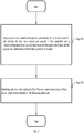
- FIG. 1 is a flowchart of an embodiment of a method of providing a hot standby for a main control unit according to a specific implementation of the present disclosure, as shown in FIG. 1 , a second main control unit performs hot standby for a first main control unit, if a failure occurs in one or more modules contained in the first main control unit, it directly switches from the first main control unit to the second main control unit, the second main control unit controls a first controlled unit to receive information from a ground subsystem.
- the method of providing a hot standby for a main control unit comprises:
- the second main control unit provides a hot standby for the first main control unit, if a failure occurs in one or more modules of the first main control unit, it switches in entirety from the first main control unit to the second main control unit, the second main control unit controls the first controlled unit to receive information from the ground subsystem, it switches from the first main control unit to the second main control unit without stopping the train, which does not affect operation efficiency and running safety of the train.
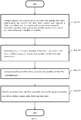
- FIG. 2 is a flowchart of a method of providing a hot standby for a main control unit according to a specific implementation of the present disclosure, as shown in FIG. 2 , after failure occurs in one or more modules of the first main control unit, if there is a second controlled unit that provides a hot standby for the first controlled unit, the second main control unit is used to directly control the second controlled unit to receive information from the ground subsystem.
- the method of providing a hot standby for a main control unit comprises:
- the second controlled unit is used to provide a hot standby for the first controlled unit, after failure occurs in the first controlled unit, the second main control unit is used to directly control the second controlled unit to receive information from the ground subsystem, that is, it switches from the fault first controlled unit to the second controlled unit without stopping the train, which does not affect operation efficiency and running safety of the train.
- the specific implementation of the present disclosure further provides a computer storage medium containing computer-executable instructions, wherein when the computer-executable instructions are processed by a data processing device, the data processing device performs the following steps:
- the specific implementation of the present disclosure further provides a computer storage medium containing computer-executable instructions, wherein when the computer-executable instructions are processed by a data processing device, the data processing device performs the following steps:
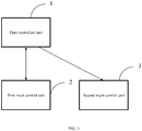
- FIG. 3 is a structural block diagram an apparatus for providing a hot standby for a main control unit according to a specific implementation of the present disclosure.
- the apparatus shown in FIG. 3 may be applied to the method shown in FIGS. 1 and 2 , the second main control unit provides a hot standby for the first main control unit, if a failure occurs in one or more modules of the first main control unit, it directly switches from the first main control unit to the second main control unit, the second main control unit controls the first controlled unit to receive information from the ground subsystem.
- the apparatus for providing a hot standby for a main control unit comprises a first controlled unit 1, a first main control unit 2, and a second main control unit 3.
- the first main controlled unit 1 is configured to receive information from a ground subsystem;
- the first main control unit 2 is connected to the first controlled unit 1, and configured to control the first controlled unit 1 to receive information from the ground subsystem, the first main control unit 2 includes a plurality of modules;
- the second main control unit 3 is connected to the first controlled unit 1, and configured to control the first controlled unit 1 to receive information from the ground subsystem when a failure occurs in one or more modules of the first main control unit 2, and provide a hot standby for the first main control unit 2.
- the modules of each of the first main control unit 2 and the second main control unit 3 specifically include a processing module, a communication module, a digital output/input module, and a power source module, etc.
- the second main control unit provides a hot standby for the first main control unit, if a failure occurs in one or more modules of the first main control unit, it switches in entirety from the first main control unit to the second main control unit, the second main control unit controls the first controlled unit to receive information from the ground subsystem, it switches from the first main control unit to the second main control unit without stopping the train, which does not affect operation efficiency and running safety of the train.
- FIG. 4 is a structural block diagram of an embodiment of an apparatus for providing a hot standby for a main control unit according to a specific implementation of the present disclosure, as shown in FIG. 4 , after failure occurs in one or more modules of the first main control unit, if there is a second controlled unit that provides a hot standby for the first controlled unit, in a case where failure occurs in the first controlled unit, the second main control unit is used to directly control the second controlled unit to receive information from the ground subsystem.
- the apparatus for providing a hot standby for a main control unit further comprises a second controlled unit 4.
- the second controlled unit 4 is connected to the second main control unit 3, and configured to be controlled by the second main control unit 3 to receive information from the ground subsystem when a failure occurs in the first controlled unit 1.
- the second controlled unit 4 is controlled by the second main control unit 3 to receive information from the ground subsystem, that is, the second main control unit 3 controls the second controlled unit 4 to receive information from the ground system.
- the first controlled unit 1 is a first BTM unit and the second controlled unit 4 is a second BTM unit.
- the second controlled unit is used to provide a hot standby for the first controlled unit, after failure occurs in the first controlled unit, the second main control unit is used to directly control the second controlled unit to receive information from the ground subsystem, that is, it switches from the first controlled unit to the second controlled unit without stopping the train, which does not affect operation efficiency and running safety of the train.
- FIG. 5 is a flowchart of an embodiment of a method of providing a hot standby for a main control unit according to a specific implementation of the present disclosure, as shown in FIG. 5 , the second main control unit provides a hot standby for the first main control unit, if a failure occurs in at least one module contained in the first main control unit, only the fault module of the first main control unit is switched, the non-fault modules of the first main control unit still operate normally.
- the method of providing a hot standby for the main control unit comprises:
- the second main control unit provides a hot standby for the first main control unit, if a failure occurs in one or more modules of the first main control unit, only the fault module of the first main control unit is switched, there is no need to stop the train, the non-fault modules of the first main control unit continue to operate, the fault module of first main control unit is replaced by the corresponding module in the second main control unit, rather than switching from the first main control unit to the second main control unit in entirety, which will not affect normal operating of the train, operation efficiency of the train is high and driving safety is high.
- FIG. 6 is a flowchart of a method of providing a hot standby for a main control unit according to a specific implementation of the present disclosure, as shown in FIG. 6 , if there is a second controlled unit that provides a hot standby for the first controlled unit, if a failure occurs in the first controlled unit, it directly switches from the first controlled unit to the second controlled unit.
- the method of providing a hot standby for a main control unit further comprises:
- the second controlled unit is used to provide a hot standby for the first controlled unit, after failure occurs in the first controlled unit, the second main control unit is used to directly control the second controlled unit to receive information from the ground subsystem, that is, it switches from the fault first controlled unit to the second controlled unit without stopping the train, which improves operation efficiency of the train and ensures running safety of the train.
- the specific implementation of the present disclosure further provides a computer storage medium containing computer-executable instructions, wherein when the computer-executable instructions are processed by a data processing device, the data processing device performs the following steps:
- the specific implementation of the present disclosure further provides a computer storage medium containing computer-executable instructions, wherein when the computer-executable instructions are processed by a data processing device, the data processing device performs the following steps:
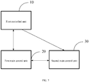
- FIG. 7 is a structural block diagram of an of an apparatus for providing a hot standby for a main control unit according to a specific implementation of the present disclosure, as shown in FIG. 7 , the second main control unit provides a hot standby for the first main control unit, if a failure occurs in at least one module included in the first main control unit, only the fault module is switched, the non-fault modules of the first main control unit still maintain normal operating.
- the apparatus for providing a hot standby for the main control unit comprises: a first controlled unit 10, a first main control unit 20, and a second main control unit 30.
- the first controlled unit 10 is configured to receive information from a ground subsystem;
- the first main control unit 20 is connected to the first controlled unit 10, and configured to control the first controlled unit 10 to receive information from the ground subsystem, the first main control unit 20 includes a plurality of modules;
- the second main control unit 30 is connected to the first controlled unit 10, and configured to switch only the fault module of the first main control unit 20 when a failure occurs in one or more modules of the first main control unit 20.
- the second main control unit provides a hot standby for the first main control unit, if a failure occurs in one or more modules of the first main control unit, only the fault module of the first main control unit is switched, there is no need to stop the train, the non-fault modules of the first main control unit continue to operate, the fault module of the first main control unit is replaced by the corresponding module in the second main control unit, rather than switching from the first main control unit to the second main control unit in entirety, which will not affect normal operating of the train, operation efficiency of the train is high and driving safety is high.
- FIG. 8 is a structural block diagram of an apparatus for providing a hot standby for a main control unit according to a specific implementation of the present disclosure, as shown in FIG. 8 , if there is a second controlled unit that provides a hot standby for the first controlled unit, when a failure occurs in the first controlled unit, it directly switches from the first controlled unit to the second controlled unit.
- the apparatus for providing a hot standby for a main control unit further comprises: a second controlled unit 40.
- the second controlled unit 40 is connected to the second main control unit 30, and configured to provide a hot standby for the first controlled unit 10.
- the second main control unit controls the second controlled unit to receive information from the ground subsystem.
- the first controlled unit 10 is a first BTM unit and the second controlled unit 40 is a second BTM unit.
- the second controlled unit is used to provide a hot standby for the first controlled unit, after failure occurs in the first controlled unit, the second main control unit is used to directly control the second controlled unit to receive information from the ground subsystem, that is, it switches from the fault first controlled unit to the second controlled unit without stopping the train, which improves operation efficiency of the train and ensures running safety of the train.
- the embodiments of the present disclosure further provide a method and apparatus of providing a hot standby for a main control unit and the computer storage medium: the second main control unit (standby-system main control board) provides a hot standby for the first main control unit (main-system main control board); the first main control unit (main-system main control board) controls the first controlled unit (main-system controlled unit) to receive information from the ground subsystem, if a failure occurs in at least one module included in the first main control unit (e.g., the processing module, the communication module, the digital output input module, and the power source module, etc.), it switches in entirety from the first main control unit to the second main control unit, that is, the second main control unit controls the first controlled unit to receive information from the ground subsystem; if there is a second controlled unit (standby-system controlled unit, e.g., a BTM unit) that provides a hot standby for the first controlled unit (main-system controlled unit, such as a BTM unit), it switches from the first controlled unit to the second controlled
- the main control unit may be switched in entirety, or only the fault module of the main control unit may be switched, and switching may be completed without stopping the train, which does not affect operation efficiency and driving safety of the train.
- the units specified in the present disclosure may be independent devices, and may also be board cards or software/ hardware modules and so on.
- the above-described embodiments of the present disclosure may be implemented in various hardware, software codes, or a combination thereof.
- the embodiments of the present disclosure may also be program codes for executing the above method in a Digital Signal Processor (DSP).
- DSP Digital Signal Processor
- the present disclosure may also relate to a variety of functions performed by a computer processor, a digital signal processor, a microprocessor, or a Field Programmable Gate Array (FPGA).
- the above-mentioned processor may be configured to perform specific tasks in accordance with the present disclosure, which is implemented by executing machine-readable software codes or firmware codes that define a particular method disclosed by the present disclosure.
- Software codes or firmware codes may be developed into different programming languages and different formats or forms. Software codes may also be complied for different target platforms. However, different code patterns, types, and languages of software codes and other types of configuration code that perform tasks in accordance with the present disclosure do not depart from the scopes of the present disclosure.
Landscapes
- Engineering & Computer Science (AREA)
- Computer Networks & Wireless Communication (AREA)
- Signal Processing (AREA)
- Mechanical Engineering (AREA)
- Hardware Redundancy (AREA)
- Heat-Pump Type And Storage Water Heaters (AREA)
- Train Traffic Observation, Control, And Security (AREA)
- Safety Devices In Control Systems (AREA)
Claims (10)
- Verfahren zur Bereitstellung eines Hot-Standby für eine Hauptsteuereinheit, wobei das Verfahren die Schritte aufweist:Verwendung einer zweiten Hauptsteuereinheit (3) zur Bereitstellung eines Hot-Standby für eine erste Hauptsteuereinheit (2), wobei die erste Hauptsteuereinheit (2) eine erste gesteuerte Einheit (1) steuert, um Informationen von einem Boden-Teilsystem zu erhalten, wobei die erste Hauptsteuereinheit (2) und die zweite Hauptsteuereinheit (3) jeweils eine Vielzahl von Modulen aufweisen, wobei die zweite Hauptsteuereinheit (3) mit der ersten gesteuerten Einheit (1) verbunden und dafür ausgebildet ist, die erste gesteuerte Einheit (1) zu steuern, um Informationen von dem Boden-Teilsystem zu erhalten, wenn ein Fehler in einem oder mehreren Modulen der ersten Hauptsteuereinheit (2) auftritt, und um einen Hot-Standby für die erste Hauptsteuereinheit (2) bereitzustellen; unddirektes Umschalten von der ersten Hauptsteuereinheit (2) zu der zweiten Hauptsteuereinheit (3), wenn ein Fehler in einem oder mehreren Modulen der ersten Hauptsteuereinheit (2) auftritt;nach dem Schritt des direkten Umschaltens von der ersten Hauptsteuereinheit (2) zu der zweiten Hauptsteuereinheit (3), Bereitstellen eines Hot-Standby für die erste gesteuerte Einheit (1), und wenn ein Fehler in der ersten gesteuerten Einheit (1) auftritt, direkt Umschalten von der ersten gesteuerten Einheit (1) zu der zweiten gesteuerten Einheit (4);nachdem ein Hot-Standby für die erste gesteuerte Einheit unter Verwendung der zweiten gesteuerten Einheit (4) ausgeführt wurde, kommuniziert die zweite Hauptsteuereinheit (3) mit der zweiten gesteuerten Einheit (4),wobei die erste gesteuerte Einheit (1) eine erste Balisen-Übertragungsmodul-Einheit BTM und die zweiten gesteuerte Einheit (4) eine zweite Balisen-Übertragungsmodul-Einheit ist.
- Verfahren zur Bereitstellung eines Hot-Standby für eine Hauptsteuereinheit gemäß Anspruch 1, wobei die Module jeder der ersten Hauptsteuereinheit (2) und der zweiten Hauptsteuereinheit (3) insbesondere ein Verarbeitungsmodul, ein Kommunikationsmodul, ein digitales Ausgabe-/Eingabemodul und ein Energiequellenmodul aufweisen.
- Computerspeichermedium, das über den Computer ausführbare Anweisungen enthält, wobei, wenn die über den Computer ausführbaren Anweisungen von einer Datenverarbeitungsvorrichtung verarbeitet werden, die Datenverarbeitungsvorrichtung Schritte des Verfahrens zur Bereitstellung eines Hot-Standby für eine Hauptsteuereinheit gemäß einem der Ansprüche 1 bis 2 ausführt.
- Vorrichtung zur Bereitstellung eines Hot-Standby für eine Hauptsteuereinheit, wobei die Vorrichtung eine erste gesteuerte Einheit (1), eine erste Hauptsteuereinheit (2), eine zweite Hauptsteuereinheit (3) und eine zweite gesteuerte Einheit (4) aufweist, wobei die Vorrichtung dafür ausgebildet ist, das Verfahren gemäß Anspruch 1 durchzuführen.
- Vorrichtung zur Bereitstellung eines Hot-Standby für eine Hauptsteuereinheit gemäß Anspruch 4, wobei die Module jeder der ersten Hauptsteuereinheit (2) und der zweiten Hauptsteuereinheit (3) insbesondere ein Verarbeitungsmodul, ein Kommunikationsmodul, ein digitales Ausgabe-/Eingabemodul und ein Energiequellenmodul aufweisen.
- Verfahren zur Bereitstellung eines Hot-Standby für eine Hauptsteuereinheit (20), wobei das Verfahren die Schritte aufweist:Verwendung einer zweiten Hauptsteuereinheit (30) zur Bereitstellung eines Hot-Standby für eine erste Hauptsteuereinheit (20), wobei die erste Hauptsteuereinheit (20) eine erste gesteuerte Einheit (10) steuert, um Informationen von einem Boden-Teilsystem zu erhalten, wobei die erste Hauptsteuereinheit (20) und die zweite Hauptsteuereinheit (30) jeweils eine Vielzahl von Modulen aufweisen, wobei die zweite Hauptsteuereinheit (30) mit der ersten gesteuerten Einheit (10) verbunden und dafür ausgebildet ist, nur das gestörte Modul der ersten Hauptsteuereinheit (20) umzuschalten, wenn ein Fehler in einem oder mehreren Modulen der ersten Hauptsteuereinheit (20) auftritt; undwenn ein Fehler in einem oder mehreren Modulen der ersten Hauptsteuereinheit (20) auftritt, Umschalten nur des/der gestörten Moduls/Module der ersten Hauptsteuereinheit (20) und Aufrechterhalten des Betriebs der restlichen nicht gestörten Module der ersten Hauptsteuereinheit (20);nach dem Schritt des Umschaltens nur des/der gestörten Moduls/Module der ersten Hauptsteuereinheit (20), Verwendung einer zweiten gesteuerten Einheit (40) zur Bereitstellung eines Hot-Standby für die erste gesteuerte Einheit (10), und wenn ein Fehler in der ersten gesteuerten Einheit (1) auftritt, direktes Umschalten von der ersten gesteuerten Einheit (1) zu der zweiten gesteuerten Einheit (4);wobei die erste gesteuerte Einheit eine erste Balisen-Übertragungsmodul-Einheit BTM und die zweiten gesteuerte Einheit (4) eine zweite Balisen-Übertragungsmodul-Einheit BTM ist.
- Verfahren zur Bereitstellung eines Hot-Standby für eine Hauptsteuereinheit gemäß Anspruch 6, wobei die Module jeweils der ersten Hauptsteuereinheit (20) und der zweiten Hauptsteuereinheit (30) insbesondere ein Verarbeitungsmodul, ein Kommunikationsmodul, ein digitales Ausgabe-/Eingabemodul und ein Energiequellenmodul aufweisen.
- Computerspeichermedium, das über den Computer ausführbare Anweisungen enthält, wobei, wenn die über den Computer ausführbaren Anweisungen von einer Datenverarbeitungsvorrichtung verarbeitet werden, die Datenverarbeitungsvorrichtung Schritte des Verfahrens zur Bereitstellung eines Hot-Standby für eine Hauptsteuereinheit gemäß einem der Ansprüche 6 bis 7 ausführt.
- Vorrichtung zur Bereitstellung eines Hot-Standby für eine Hauptsteuereinheit, wobei die Vorrichtung eine erste gesteuerte Einheit (10), eine erste Hauptsteuereinheit (20), eine zweite Hauptsteuereinheit (30) und eine zweite gesteuerte Einheit (40) aufweist, wobei die Vorrichtung dafür ausgebildet ist, das Verfahren gemäß Anspruch 6 durchzuführen.
- Vorrichtung zur Bereitstellung eines Hot-Standby für eine Hauptsteuereinheit gemäß Anspruch 9, wobei die Module jeder der ersten Hauptsteuereinheit und der zweiten Hauptsteuereinheit insbesondere ein Verarbeitungsmodul, ein Kommunikationsmodul, ein digitales Ausgabe-/Eingabemodul und ein Energiequellenmodul aufweisen.
Priority Applications (2)
| Application Number | Priority Date | Filing Date | Title |
|---|---|---|---|
| HRP20220445TT HRP20220445T1 (hr) | 2017-11-14 | 2018-05-08 | Metoda i uređaj za “hot backup“ glavne upravljačke jedinice i medija za pohranu računala |
| RS20220137A RS62908B1 (sr) | 2017-11-14 | 2018-05-08 | Postupak i uređaj za vruću rezervu glavne upravljačke jedinice i računarski medijum za skladištenje |
Applications Claiming Priority (2)
| Application Number | Priority Date | Filing Date | Title |
|---|---|---|---|
| CN201711120641.0A CN108092752B (zh) | 2017-11-14 | 2017-11-14 | 一种基于列车运行控制系统的主控单元热备份方法及装置 |
| PCT/CN2018/086024 WO2019095647A1 (zh) | 2017-11-14 | 2018-05-08 | 主控单元热备份的方法及装置、计算机存储介质 |
Publications (3)
| Publication Number | Publication Date |
|---|---|
| EP3713127A1 EP3713127A1 (de) | 2020-09-23 |
| EP3713127A4 EP3713127A4 (de) | 2021-01-13 |
| EP3713127B1 true EP3713127B1 (de) | 2022-01-05 |
Family
ID=62172174
Family Applications (1)
| Application Number | Title | Priority Date | Filing Date |
|---|---|---|---|
| EP18878542.2A Active EP3713127B1 (de) | 2017-11-14 | 2018-05-08 | Verfahren und vorrichtung für ein hot-backup einer hauptsteuereinheit und computerspeichermedium |
Country Status (7)
| Country | Link |
|---|---|
| EP (1) | EP3713127B1 (de) |
| CN (1) | CN108092752B (de) |
| EA (1) | EA201992084A1 (de) |
| HR (1) | HRP20220445T1 (de) |
| HU (1) | HUE058234T2 (de) |
| RS (1) | RS62908B1 (de) |
| WO (1) | WO2019095647A1 (de) |
Families Citing this family (3)
| Publication number | Priority date | Publication date | Assignee | Title |
|---|---|---|---|---|
| CN110789569B (zh) * | 2019-10-17 | 2022-04-22 | 北京全路通信信号研究设计院集团有限公司 | 一种列控dmi数据冗余控制方法和系统 |
| CN110979406A (zh) * | 2019-12-26 | 2020-04-10 | 天津津航计算技术研究所 | 一种交叉复用的信号系统安全计算平台 |
| CN113746664B (zh) * | 2021-07-12 | 2024-09-06 | 浙江众合科技股份有限公司 | 基于状态机的冗余架构设备资源管理方法 |
Family Cites Families (8)
| Publication number | Priority date | Publication date | Assignee | Title |
|---|---|---|---|---|
| EP0749663B1 (de) * | 1994-03-08 | 1999-12-01 | Excel Switching Corporation | Fernmeldevermittlungsanlage mit verbesserter redundanz |
| US7170895B2 (en) * | 2002-03-29 | 2007-01-30 | Tropic Networks Inc. | Switch and a switching apparatus for a communication network |
| US20070073453A1 (en) * | 2005-09-29 | 2007-03-29 | Siemens Aktiengesellschaft | System architecture for controlling and monitoring components of a railroad safety installation |
| JP4966888B2 (ja) * | 2008-02-25 | 2012-07-04 | 株式会社日立製作所 | 二重系列車制御装置 |
| CN102951182A (zh) * | 2012-10-18 | 2013-03-06 | 上海亨钧科技有限公司 | 一种铁路专用安全计算机的工作方法 |
| CN103802862B (zh) * | 2013-12-02 | 2016-01-27 | 北京铁路信号有限公司 | 一种列车运行控制系统3级列控车载控制系统机柜 |
| CN104503272A (zh) * | 2014-11-20 | 2015-04-08 | 北京交控科技有限公司 | 基于双系热备冗余的列车自动驾驶系统 |
| CN107187465B (zh) * | 2017-06-09 | 2020-06-02 | 湖南中车时代通信信号有限公司 | 一种单元级热备冗余的ato系统架构 |
-
2017
- 2017-11-14 CN CN201711120641.0A patent/CN108092752B/zh active Active
-
2018
- 2018-05-08 EP EP18878542.2A patent/EP3713127B1/de active Active
- 2018-05-08 RS RS20220137A patent/RS62908B1/sr unknown
- 2018-05-08 HR HRP20220445TT patent/HRP20220445T1/hr unknown
- 2018-05-08 HU HUE18878542A patent/HUE058234T2/hu unknown
- 2018-05-08 EA EA201992084A patent/EA201992084A1/ru unknown
- 2018-05-08 WO PCT/CN2018/086024 patent/WO2019095647A1/zh not_active Ceased
Also Published As
| Publication number | Publication date |
|---|---|
| WO2019095647A1 (zh) | 2019-05-23 |
| HUE058234T2 (hu) | 2022-07-28 |
| CN108092752A (zh) | 2018-05-29 |
| EA201992084A1 (ru) | 2020-07-30 |
| HRP20220445T1 (hr) | 2022-06-10 |
| RS62908B1 (sr) | 2022-03-31 |
| CN108092752B (zh) | 2020-10-23 |
| EP3713127A4 (de) | 2021-01-13 |
| EP3713127A1 (de) | 2020-09-23 |
Similar Documents
| Publication | Publication Date | Title |
|---|---|---|
| EP4159578A1 (de) | Zugintervallschutzsteuerungsverfahren und -vorrichtung auf der basis eines tacs-systems | |
| EP4414242A1 (de) | Integriertes tacs- und tbtc-signalisierungssystem und schaltverfahren dafür | |
| US8620497B2 (en) | Computer interlocking system and code bit level redundancy method therefor | |
| CN108177662B (zh) | 一种不同列车运行制式的atp限速曲线融合方法 | |
| CN109946956B (zh) | 一种设备主备系同步和热备方法 | |
| EP3713127B1 (de) | Verfahren und vorrichtung für ein hot-backup einer hauptsteuereinheit und computerspeichermedium | |
| CN101700783B (zh) | 一种列控中心系统平台 | |
| US20150225003A1 (en) | Control of a rail vehicle | |
| CN110979404B (zh) | 列车自动监督系统的双机热备系统及方法 | |
| CN114228788B (zh) | 一种失位列车的轨旁辅助定位方法、装置、设备及介质 | |
| CN104129406A (zh) | 一种传输轨道电路信息的设备与方法 | |
| CN110758489A (zh) | 一种列车自动防护系统 | |
| CN104401365A (zh) | Ato双机热备的实现方法和ato双机热备 | |
| CN115892144B (zh) | 一种tacs系统主备定位转换方法、装置、设备及介质 | |
| US20150239481A1 (en) | Operation of a rail vehicle by means of an ETCS device | |
| CN201941780U (zh) | 一种基于tms570的atp车载二乘二取二系统 | |
| CN111071306B (zh) | 一种ctcs-2列控系统调试方法 | |
| KR20140061929A (ko) | 철도차량의 제동지령 전달 및 추종방법 | |
| CN110293999B (zh) | 一种安全型lkj制动控制方式 | |
| CN101931519A (zh) | 基于同步通信交换的三模冗余实现方法 | |
| CN111572597B (zh) | 一种列车过分相区操作方法、装置、设备及计算机可读存储介质 | |
| WO2026051197A1 (zh) | 一种列车自主运行控制系统、方法、设备及介质 | |
| EP4722074A1 (de) | Redundantes system und verfahren zur steuerung des redundanten systems | |
| CN108082221A (zh) | 车载tcr热备份的方法及装置、计算机可读介质 | |
| CN108032877A (zh) | 车载btm单元热备份的方法及装置、计算机可读介质 |
Legal Events
| Date | Code | Title | Description |
|---|---|---|---|
| REG | Reference to a national code |
Ref country code: HR Ref legal event code: TUEP Ref document number: P20220445T Country of ref document: HR |
|
| STAA | Information on the status of an ep patent application or granted ep patent |
Free format text: STATUS: THE INTERNATIONAL PUBLICATION HAS BEEN MADE |
|
| PUAI | Public reference made under article 153(3) epc to a published international application that has entered the european phase |
Free format text: ORIGINAL CODE: 0009012 |
|
| STAA | Information on the status of an ep patent application or granted ep patent |
Free format text: STATUS: REQUEST FOR EXAMINATION WAS MADE |
|
| 17P | Request for examination filed |
Effective date: 20200611 |
|
| AK | Designated contracting states |
Kind code of ref document: A1 Designated state(s): AL AT BE BG CH CY CZ DE DK EE ES FI FR GB GR HR HU IE IS IT LI LT LU LV MC MK MT NL NO PL PT RO RS SE SI SK SM TR |
|
| AX | Request for extension of the european patent |
Extension state: BA ME |
|
| A4 | Supplementary search report drawn up and despatched |
Effective date: 20201211 |
|
| RIC1 | Information provided on ipc code assigned before grant |
Ipc: H04L 1/22 20060101AFI20201207BHEP Ipc: B61L 27/00 20060101ALI20201207BHEP |
|
| DAV | Request for validation of the european patent (deleted) | ||
| DAX | Request for extension of the european patent (deleted) | ||
| GRAP | Despatch of communication of intention to grant a patent |
Free format text: ORIGINAL CODE: EPIDOSNIGR1 |
|
| STAA | Information on the status of an ep patent application or granted ep patent |
Free format text: STATUS: GRANT OF PATENT IS INTENDED |
|
| INTG | Intention to grant announced |
Effective date: 20210726 |
|
| GRAS | Grant fee paid |
Free format text: ORIGINAL CODE: EPIDOSNIGR3 |
|
| GRAA | (expected) grant |
Free format text: ORIGINAL CODE: 0009210 |
|
| STAA | Information on the status of an ep patent application or granted ep patent |
Free format text: STATUS: THE PATENT HAS BEEN GRANTED |
|
| AK | Designated contracting states |
Kind code of ref document: B1 Designated state(s): AL AT BE BG CH CY CZ DE DK EE ES FI FR GB GR HR HU IE IS IT LI LT LU LV MC MK MT NL NO PL PT RO RS SE SI SK SM TR |
|
| REG | Reference to a national code |
Ref country code: GB Ref legal event code: FG4D |
|
| REG | Reference to a national code |
Ref country code: CH Ref legal event code: EP |
|
| REG | Reference to a national code |
Ref country code: AT Ref legal event code: REF Ref document number: 1461529 Country of ref document: AT Kind code of ref document: T Effective date: 20220115 |
|
| REG | Reference to a national code |
Ref country code: DE Ref legal event code: R096 Ref document number: 602018029366 Country of ref document: DE |
|
| REG | Reference to a national code |
Ref country code: IE Ref legal event code: FG4D |
|
| REG | Reference to a national code |
Ref country code: RO Ref legal event code: EPE |
|
| REG | Reference to a national code |
Ref country code: SE Ref legal event code: TRGR |
|
| REG | Reference to a national code |
Ref country code: LT Ref legal event code: MG9D |
|
| REG | Reference to a national code |
Ref country code: NL Ref legal event code: MP Effective date: 20220105 |
|
| REG | Reference to a national code |
Ref country code: HR Ref legal event code: ODRP Ref document number: P20220445T Country of ref document: HR Payment date: 20220503 Year of fee payment: 5 |
|
| REG | Reference to a national code |
Ref country code: HR Ref legal event code: T1PR Ref document number: P20220445 Country of ref document: HR |
|
| PG25 | Lapsed in a contracting state [announced via postgrant information from national office to epo] |
Ref country code: NL Free format text: LAPSE BECAUSE OF FAILURE TO SUBMIT A TRANSLATION OF THE DESCRIPTION OR TO PAY THE FEE WITHIN THE PRESCRIBED TIME-LIMIT Effective date: 20220105 |
|
| REG | Reference to a national code |
Ref country code: HU Ref legal event code: AG4A Ref document number: E058234 Country of ref document: HU |
|
| PG25 | Lapsed in a contracting state [announced via postgrant information from national office to epo] |
Ref country code: PT Free format text: LAPSE BECAUSE OF FAILURE TO SUBMIT A TRANSLATION OF THE DESCRIPTION OR TO PAY THE FEE WITHIN THE PRESCRIBED TIME-LIMIT Effective date: 20220505 Ref country code: NO Free format text: LAPSE BECAUSE OF FAILURE TO SUBMIT A TRANSLATION OF THE DESCRIPTION OR TO PAY THE FEE WITHIN THE PRESCRIBED TIME-LIMIT Effective date: 20220405 Ref country code: LT Free format text: LAPSE BECAUSE OF FAILURE TO SUBMIT A TRANSLATION OF THE DESCRIPTION OR TO PAY THE FEE WITHIN THE PRESCRIBED TIME-LIMIT Effective date: 20220105 Ref country code: ES Free format text: LAPSE BECAUSE OF FAILURE TO SUBMIT A TRANSLATION OF THE DESCRIPTION OR TO PAY THE FEE WITHIN THE PRESCRIBED TIME-LIMIT Effective date: 20220105 Ref country code: BG Free format text: LAPSE BECAUSE OF FAILURE TO SUBMIT A TRANSLATION OF THE DESCRIPTION OR TO PAY THE FEE WITHIN THE PRESCRIBED TIME-LIMIT Effective date: 20220405 |
|
| PG25 | Lapsed in a contracting state [announced via postgrant information from national office to epo] |
Ref country code: PL Free format text: LAPSE BECAUSE OF FAILURE TO SUBMIT A TRANSLATION OF THE DESCRIPTION OR TO PAY THE FEE WITHIN THE PRESCRIBED TIME-LIMIT Effective date: 20220105 Ref country code: LV Free format text: LAPSE BECAUSE OF FAILURE TO SUBMIT A TRANSLATION OF THE DESCRIPTION OR TO PAY THE FEE WITHIN THE PRESCRIBED TIME-LIMIT Effective date: 20220105 Ref country code: GR Free format text: LAPSE BECAUSE OF FAILURE TO SUBMIT A TRANSLATION OF THE DESCRIPTION OR TO PAY THE FEE WITHIN THE PRESCRIBED TIME-LIMIT Effective date: 20220406 Ref country code: FI Free format text: LAPSE BECAUSE OF FAILURE TO SUBMIT A TRANSLATION OF THE DESCRIPTION OR TO PAY THE FEE WITHIN THE PRESCRIBED TIME-LIMIT Effective date: 20220105 |
|
| PG25 | Lapsed in a contracting state [announced via postgrant information from national office to epo] |
Ref country code: IS Free format text: LAPSE BECAUSE OF FAILURE TO SUBMIT A TRANSLATION OF THE DESCRIPTION OR TO PAY THE FEE WITHIN THE PRESCRIBED TIME-LIMIT Effective date: 20220505 |
|
| REG | Reference to a national code |
Ref country code: DE Ref legal event code: R097 Ref document number: 602018029366 Country of ref document: DE |
|
| PG25 | Lapsed in a contracting state [announced via postgrant information from national office to epo] |
Ref country code: SM Free format text: LAPSE BECAUSE OF FAILURE TO SUBMIT A TRANSLATION OF THE DESCRIPTION OR TO PAY THE FEE WITHIN THE PRESCRIBED TIME-LIMIT Effective date: 20220105 Ref country code: SK Free format text: LAPSE BECAUSE OF FAILURE TO SUBMIT A TRANSLATION OF THE DESCRIPTION OR TO PAY THE FEE WITHIN THE PRESCRIBED TIME-LIMIT Effective date: 20220105 Ref country code: EE Free format text: LAPSE BECAUSE OF FAILURE TO SUBMIT A TRANSLATION OF THE DESCRIPTION OR TO PAY THE FEE WITHIN THE PRESCRIBED TIME-LIMIT Effective date: 20220105 Ref country code: DK Free format text: LAPSE BECAUSE OF FAILURE TO SUBMIT A TRANSLATION OF THE DESCRIPTION OR TO PAY THE FEE WITHIN THE PRESCRIBED TIME-LIMIT Effective date: 20220105 Ref country code: CZ Free format text: LAPSE BECAUSE OF FAILURE TO SUBMIT A TRANSLATION OF THE DESCRIPTION OR TO PAY THE FEE WITHIN THE PRESCRIBED TIME-LIMIT Effective date: 20220105 |
|
| PLBE | No opposition filed within time limit |
Free format text: ORIGINAL CODE: 0009261 |
|
| STAA | Information on the status of an ep patent application or granted ep patent |
Free format text: STATUS: NO OPPOSITION FILED WITHIN TIME LIMIT |
|
| PG25 | Lapsed in a contracting state [announced via postgrant information from national office to epo] |
Ref country code: AL Free format text: LAPSE BECAUSE OF FAILURE TO SUBMIT A TRANSLATION OF THE DESCRIPTION OR TO PAY THE FEE WITHIN THE PRESCRIBED TIME-LIMIT Effective date: 20220105 |
|
| 26N | No opposition filed |
Effective date: 20221006 |
|
| REG | Reference to a national code |
Ref country code: CH Ref legal event code: PL |
|
| REG | Reference to a national code |
Ref country code: BE Ref legal event code: MM Effective date: 20220531 |
|
| GBPC | Gb: european patent ceased through non-payment of renewal fee |
Effective date: 20220508 |
|
| PG25 | Lapsed in a contracting state [announced via postgrant information from national office to epo] |
Ref country code: MC Free format text: LAPSE BECAUSE OF FAILURE TO SUBMIT A TRANSLATION OF THE DESCRIPTION OR TO PAY THE FEE WITHIN THE PRESCRIBED TIME-LIMIT Effective date: 20220105 Ref country code: LU Free format text: LAPSE BECAUSE OF NON-PAYMENT OF DUE FEES Effective date: 20220508 Ref country code: LI Free format text: LAPSE BECAUSE OF NON-PAYMENT OF DUE FEES Effective date: 20220531 Ref country code: CH Free format text: LAPSE BECAUSE OF NON-PAYMENT OF DUE FEES Effective date: 20220531 |
|
| REG | Reference to a national code |
Ref country code: AT Ref legal event code: UEP Ref document number: 1461529 Country of ref document: AT Kind code of ref document: T Effective date: 20220105 |
|
| PG25 | Lapsed in a contracting state [announced via postgrant information from national office to epo] |
Ref country code: SI Free format text: LAPSE BECAUSE OF FAILURE TO SUBMIT A TRANSLATION OF THE DESCRIPTION OR TO PAY THE FEE WITHIN THE PRESCRIBED TIME-LIMIT Effective date: 20220105 |
|
| PG25 | Lapsed in a contracting state [announced via postgrant information from national office to epo] |
Ref country code: IE Free format text: LAPSE BECAUSE OF NON-PAYMENT OF DUE FEES Effective date: 20220508 |
|
| REG | Reference to a national code |
Ref country code: HR Ref legal event code: ODRP Ref document number: P20220445 Country of ref document: HR Payment date: 20230505 Year of fee payment: 6 |
|
| PG25 | Lapsed in a contracting state [announced via postgrant information from national office to epo] |
Ref country code: GB Free format text: LAPSE BECAUSE OF NON-PAYMENT OF DUE FEES Effective date: 20220508 Ref country code: BE Free format text: LAPSE BECAUSE OF NON-PAYMENT OF DUE FEES Effective date: 20220531 |
|
| PG25 | Lapsed in a contracting state [announced via postgrant information from national office to epo] |
Ref country code: IT Free format text: LAPSE BECAUSE OF FAILURE TO SUBMIT A TRANSLATION OF THE DESCRIPTION OR TO PAY THE FEE WITHIN THE PRESCRIBED TIME-LIMIT Effective date: 20220105 |
|
| PG25 | Lapsed in a contracting state [announced via postgrant information from national office to epo] |
Ref country code: MK Free format text: LAPSE BECAUSE OF FAILURE TO SUBMIT A TRANSLATION OF THE DESCRIPTION OR TO PAY THE FEE WITHIN THE PRESCRIBED TIME-LIMIT Effective date: 20220105 Ref country code: CY Free format text: LAPSE BECAUSE OF FAILURE TO SUBMIT A TRANSLATION OF THE DESCRIPTION OR TO PAY THE FEE WITHIN THE PRESCRIBED TIME-LIMIT Effective date: 20220105 |
|
| REG | Reference to a national code |
Ref country code: HR Ref legal event code: ODRP Ref document number: P20220445 Country of ref document: HR Payment date: 20240429 Year of fee payment: 7 |
|
| PG25 | Lapsed in a contracting state [announced via postgrant information from national office to epo] |
Ref country code: MT Free format text: LAPSE BECAUSE OF FAILURE TO SUBMIT A TRANSLATION OF THE DESCRIPTION OR TO PAY THE FEE WITHIN THE PRESCRIBED TIME-LIMIT Effective date: 20220105 |
|
| REG | Reference to a national code |
Ref country code: HR Ref legal event code: ODRP Ref document number: P20220445 Country of ref document: HR Payment date: 20250415 Year of fee payment: 8 |
|
| PGFP | Annual fee paid to national office [announced via postgrant information from national office to epo] |
Ref country code: DE Payment date: 20250519 Year of fee payment: 8 |
|
| PGFP | Annual fee paid to national office [announced via postgrant information from national office to epo] |
Ref country code: RS Payment date: 20250408 Year of fee payment: 8 Ref country code: HU Payment date: 20250526 Year of fee payment: 8 |
|
| PGFP | Annual fee paid to national office [announced via postgrant information from national office to epo] |
Ref country code: HR Payment date: 20250415 Year of fee payment: 8 |
|
| PGFP | Annual fee paid to national office [announced via postgrant information from national office to epo] |
Ref country code: FR Payment date: 20250402 Year of fee payment: 8 |
|
| PGFP | Annual fee paid to national office [announced via postgrant information from national office to epo] |
Ref country code: RO Payment date: 20250422 Year of fee payment: 8 Ref country code: AT Payment date: 20250519 Year of fee payment: 8 |
|
| PGFP | Annual fee paid to national office [announced via postgrant information from national office to epo] |
Ref country code: TR Payment date: 20250403 Year of fee payment: 8 |
|
| PGFP | Annual fee paid to national office [announced via postgrant information from national office to epo] |
Ref country code: SE Payment date: 20250407 Year of fee payment: 8 |