EP3713162B1 - Procédé et appareil de traitement de route - Google Patents
Procédé et appareil de traitement de route Download PDFInfo
- Publication number
- EP3713162B1 EP3713162B1 EP18883637.3A EP18883637A EP3713162B1 EP 3713162 B1 EP3713162 B1 EP 3713162B1 EP 18883637 A EP18883637 A EP 18883637A EP 3713162 B1 EP3713162 B1 EP 3713162B1
- Authority
- EP
- European Patent Office
- Prior art keywords
- path
- srv6
- sid
- packet
- vpn sid
- Prior art date
- Legal status (The legal status is an assumption and is not a legal conclusion. Google has not performed a legal analysis and makes no representation as to the accuracy of the status listed.)
- Active
Links
Images


Classifications
-
- H—ELECTRICITY
- H04—ELECTRIC COMMUNICATION TECHNIQUE
- H04L—TRANSMISSION OF DIGITAL INFORMATION, e.g. TELEGRAPHIC COMMUNICATION
- H04L45/00—Routing or path finding of packets in data switching networks
- H04L45/28—Routing or path finding of packets in data switching networks using route fault recovery
-
- H—ELECTRICITY
- H04—ELECTRIC COMMUNICATION TECHNIQUE
- H04L—TRANSMISSION OF DIGITAL INFORMATION, e.g. TELEGRAPHIC COMMUNICATION
- H04L12/00—Data switching networks
- H04L12/28—Data switching networks characterised by path configuration, e.g. LAN [Local Area Networks] or WAN [Wide Area Networks]
- H04L12/46—Interconnection of networks
- H04L12/4604—LAN interconnection over a backbone network, e.g. Internet, Frame Relay
- H04L12/462—LAN interconnection over a bridge based backbone
- H04L12/4625—Single bridge functionality, e.g. connection of two networks over a single bridge
-
- H—ELECTRICITY
- H04—ELECTRIC COMMUNICATION TECHNIQUE
- H04L—TRANSMISSION OF DIGITAL INFORMATION, e.g. TELEGRAPHIC COMMUNICATION
- H04L12/00—Data switching networks
- H04L12/28—Data switching networks characterised by path configuration, e.g. LAN [Local Area Networks] or WAN [Wide Area Networks]
- H04L12/46—Interconnection of networks
- H04L12/4633—Interconnection of networks using encapsulation techniques, e.g. tunneling
-
- H—ELECTRICITY
- H04—ELECTRIC COMMUNICATION TECHNIQUE
- H04L—TRANSMISSION OF DIGITAL INFORMATION, e.g. TELEGRAPHIC COMMUNICATION
- H04L12/00—Data switching networks
- H04L12/28—Data switching networks characterised by path configuration, e.g. LAN [Local Area Networks] or WAN [Wide Area Networks]
- H04L12/46—Interconnection of networks
- H04L12/4641—Virtual LANs, VLANs, e.g. virtual private networks [VPN]
-
- H—ELECTRICITY
- H04—ELECTRIC COMMUNICATION TECHNIQUE
- H04L—TRANSMISSION OF DIGITAL INFORMATION, e.g. TELEGRAPHIC COMMUNICATION
- H04L12/00—Data switching networks
- H04L12/28—Data switching networks characterised by path configuration, e.g. LAN [Local Area Networks] or WAN [Wide Area Networks]
- H04L12/46—Interconnection of networks
- H04L12/4641—Virtual LANs, VLANs, e.g. virtual private networks [VPN]
- H04L12/4675—Dynamic sharing of VLAN information amongst network nodes
-
- H—ELECTRICITY
- H04—ELECTRIC COMMUNICATION TECHNIQUE
- H04L—TRANSMISSION OF DIGITAL INFORMATION, e.g. TELEGRAPHIC COMMUNICATION
- H04L45/00—Routing or path finding of packets in data switching networks
- H04L45/02—Topology update or discovery
- H04L45/03—Topology update or discovery by updating link state protocols
-
- H—ELECTRICITY
- H04—ELECTRIC COMMUNICATION TECHNIQUE
- H04L—TRANSMISSION OF DIGITAL INFORMATION, e.g. TELEGRAPHIC COMMUNICATION
- H04L45/00—Routing or path finding of packets in data switching networks
- H04L45/02—Topology update or discovery
- H04L45/04—Interdomain routing, e.g. hierarchical routing
-
- H—ELECTRICITY
- H04—ELECTRIC COMMUNICATION TECHNIQUE
- H04L—TRANSMISSION OF DIGITAL INFORMATION, e.g. TELEGRAPHIC COMMUNICATION
- H04L45/00—Routing or path finding of packets in data switching networks
- H04L45/22—Alternate routing
-
- H—ELECTRICITY
- H04—ELECTRIC COMMUNICATION TECHNIQUE
- H04L—TRANSMISSION OF DIGITAL INFORMATION, e.g. TELEGRAPHIC COMMUNICATION
- H04L45/00—Routing or path finding of packets in data switching networks
- H04L45/34—Source routing
-
- H—ELECTRICITY
- H04—ELECTRIC COMMUNICATION TECHNIQUE
- H04L—TRANSMISSION OF DIGITAL INFORMATION, e.g. TELEGRAPHIC COMMUNICATION
- H04L45/00—Routing or path finding of packets in data switching networks
- H04L45/50—Routing or path finding of packets in data switching networks using label swapping, e.g. multi-protocol label switch [MPLS]
-
- H—ELECTRICITY
- H04—ELECTRIC COMMUNICATION TECHNIQUE
- H04L—TRANSMISSION OF DIGITAL INFORMATION, e.g. TELEGRAPHIC COMMUNICATION
- H04L45/00—Routing or path finding of packets in data switching networks
- H04L45/74—Address processing for routing
-
- H—ELECTRICITY
- H04—ELECTRIC COMMUNICATION TECHNIQUE
- H04L—TRANSMISSION OF DIGITAL INFORMATION, e.g. TELEGRAPHIC COMMUNICATION
- H04L63/00—Network architectures or network communication protocols for network security
- H04L63/02—Network architectures or network communication protocols for network security for separating internal from external traffic, e.g. firewalls
- H04L63/0272—Virtual private networks
Definitions
- This application relates to the field of communications technologies, and in particular, to a route processing method and an apparatus, and a data transmission method and an apparatus.
- a customer edge (CE) device is multi-homed to a provider edge (PE) device.
- the CE device is simultaneously connected to a plurality of PEs, and there are a plurality of paths from another CE device to the CE device.
- a source CE device when sending a packet to a destination CE device, sends, to a PE device connected to the source CE device, the packet to be transmitted to the destination CE device.
- the PE device connected to the source CE device may determine, from a plurality of paths to the destination CE device, a path to transmit the packet, and transmit the packet through the path.
- bidirectional forwarding detection is usually configured between the PE device connected to the source CE device and the PE device connected to the destination CE device.
- BFD bidirectional forwarding detection
- the PE device connected to the source CE device may detect, based on BFD between the PE device connected to the source CE device and the PE that is connected to the destination CE and that is on the path, whether the PE device that is connected to the destination CE device and that is on the path is faulty.
- the PE device connected to the source CE device transmits the packet on another path to the destination CE device through switching, to ensure that the packet can be transmitted to the destination CE device.
- each PE device accesses a plurality of CE devices, and each PE device establishes a path with a plurality of other PE devices in the network.
- BFD needs to be deployed on PE devices that establish a path between the PE devices. Therefore, an amount of BFD deployed on each PE device can be equal to a quantity of paths established between the PE device and other PE devices. As a result, a relatively large amount of BFD needs to be deployed on each PE device, and excessive resources are occupied.
- Document US2015/109902A1 discloses a method that comprises selecting, by an ingress provider edge router, one of first or second provider edge routers as a primary router for reaching a destination via a core network, and selecting the other of the first or second provider edge routers as a backup router for reaching the destination via the core network; and inserting, into an IPv6 data packet destined for the destination, a primary label assigned by the primary router and a repair label assigned by backup router, and an IPv6 extension header specifying first and second segment identifiers associated with the respective first and second provider edge routers and a protected flag that enables fast rerouting of the IPv6 data packet to the backup router if the primary router is unavailable.
- SRv6-based VPN refers to the creation of VPN between PE's leveraging the SRv6 dataplane and more specifically the END.DT* (crossconnect to a VRF) and END.DX* (crossconnect to a nexthop).
- SRv6-L3 VPN refers to the creation of Layer3 VPN service between PE's supporting an SRv6 data plane.
- SRv6-EVPN refers to the creation of Layer2/Layer3 VPN service between PE's supporting an SRv6 data plane.
- BGP is used to advertise the reachability of prefixes in a particular VPN from an egress Provider Edge (egress-PE) to ingress Provider Edge (ingress-PE) nodes.
- a provide edge (PE) network device may pre-configure an interface next hop and secondary next hops.
- the secondary next hops may be logical links to other PE network devices in the same Ethernet segment.
- the PE network device may be configured to forward data traffic to the CE network device using the secondary next hops.
- the PE network device may be configured to send an out-of-service message to the CE network device that instructs the CE network device to stop sending traffic to the PE network device.
- This application provides a route processing method and an apparatus, and a data transmission method and an apparatus, to effectively reduce an amount of BFD configured on each PE.
- a method, a PE device, a system and a computer program product for rout processing and packet forwarding according to the present application are provided in the appended claims.
- a route processing method comprises: receiving, by a first provider edge, PE, device, a first virtual private network, VPN, route sent by a second PE device, wherein the first VPN route comprises a second internet protocol version 6 segment routing-based virtual private network segment identifier, SRv6 VPN SID, and a third SRv6 VPN SID, wherein a second customer edge, CE, device is multi-homed to the first PE device and the second PE device, the first PE device is configured with a first SRv6 VPN SID used to identify a VPN to which the second CE device belongs or an outgoing interface through which the first PE is connected to the second CE device, the second PE device is configured with the second SRv6 VPN SID and the third SRv6 VPN SID, both the second SRv6 VPN SID and the third SRv6 VPN SID are used to identify the VPN to which the second CE device belongs or an outgoing interface through which the second PE device is connected to the second CE device, the second SRv6 VPN SID
- the second SRv6 VPN SID is the same as the first SRv6 VPN SID. Therefore, a path to the first SRv6 VPN SID includes a path to the first PE device and a path to the second PE device. Therefore, when a packet sent by the first CE device to the second CE device is transmitted, if a fifth path to the first PE is faulty, a sixth path to the second PE device may be determined. Further, the packet may be transmitted to the second PE device on the sixth path through switching, so that the second PE device may send the packet to the second CE device.
- an ingress PE device may not detect whether an egress PE device on the path is faulty.
- the ingress PE device detects, in a packet transmission process, that the egress PE device is faulty, the packet is transmitted through a path that is to a PE device which has a same SRv6 VPN SID as the egress PE device, so that rapid path switching is implemented. Therefore, BFD does not need to be deployed, between PE devices that establish a path, to detect a fault. To be specific, BFD does not need to be deployed between the ingress PE device and the egress PE device to detect a fault.
- the second PE device is configured with the third SRv6 VPN SID that is different from the first SRv6 VPN SID, so that the first PE device may establish the second path based on the third SRv6 VPN SID in the first VPN route.
- a packet transmitted by the first PE device to the second CE device may be transmitted on the second path through switching. Therefore, rapid path switching is implemented, the packet can be transmitted to the second CE device, and multi-homing protection is implemented.
- the method further includes: sending, by the first PE device, a second VPN route to the second PE device, wherein the second VPN route carries the first SRv6 VPN SID and a fourth SRv6 VPN SID, the fourth SRv6 VPN SID is used to identify the VPN to which the second CE device belongs or the outgoing interface through which the first PE device is connected to the second CE device, the fourth SRv6 VPN SID is used by the second PE device to establish a third path from the second PE device to the first PE device, when a fourth path directly connected to the second PE device and the second CE device is faulty, the third path is used by the second PE device to transmit a packet to the second CE device, the fourth SRv6 VPN SID is different from the first SRv6 VPN SID, and the first SRv6 VPN SID is the same as the second SRv6 VPN SID stored in the second PE device.
- the first PE device is configured with the fourth SRv6 VPN SID, so that the second PE device may establish the second path based on the fourth SRv6 VPN SID.
- the second PE device may establish the second path based on the fourth SRv6 VPN SID.
- the first VPN route is carried in a border gateway protocol-prefix-segment identifier, BGP-Prefix-SID, attribute field of a multiprotocol extension for border gateway protocol, MP-BGP, message.
- BGP-Prefix-SID border gateway protocol-prefix-segment identifier
- MP-BGP multiprotocol extension for border gateway protocol
- the method further includes: receiving, by the first PE device, a first packet, wherein the first packet is sent by a first CE device to the second CE device, and an outer destination address encapsulated in the first packet is the first SRv6 VPN SID; in response to the first path is faulty, forwarding, by the first PE device based on the first SRv6 VPN SID and the third SRv6 VPN SID, the first packet through the second path.
- the packet when the first PE device transmits a packet to the second CE device, and a path directly connected to the first PE device and the second CE device is faulty, the packet may be transmitted on the second path through switching. Therefore, rapid path switching is implemented, the packet can be transmitted to the second CE device, and multi-homing protection is implemented.
- this application provides a data transmission method, and the method is applied in a network that bears an SRv6-based VPN service.
- the network includes a first CE device, a second CE device, an ingress PE device, N egress PE devices, and at least one P device.
- the first CE device is connected to the ingress PE device, and the second CE device is multi-homed to the N egress PE devices.
- the ingress PE device is communicatively connected to the N egress PE devices by using the at least one P device, and the first CE device and the second CE device belong to a same VPN.
- the N egress PE devices include a first PE device and a second PE device.
- the first PE device is configured with a first SRv6 VPN SID, and the first SRv6 VPN SID is used to identify the VPN to which the second CE device belongs or an outgoing interface through which the first PE device is connected to the second CE device.
- the second PE device is configured with a second SRv6 VPN SID and a third SRv6 VPN SID, and both the second SRv6 VPN SID and the third SRv6 VPN SID are used to identify the VPN to which the second CE device belongs or an outgoing interface through which the second PE device is connected to the second CE device.
- the first SRv6 VPN SID is the same as the second SRv6 VPN SID, and N is an integer greater than or equal to 2.
- the method includes: receiving, by the first PE device, a first packet, where the first packet is sent by the first CE device to the second CE device, and an outer destination address encapsulated in the first packet is the first SRv6 VPN SID; determining, by the first PE device based on the first SRv6 VPN SID, a first path for forwarding the first packet, where the first path is directly connected to the first PE device and the second CE device; determining, by the first PE device, that the first path is faulty, and determining, by the first PE device based on the first SRv6 VPN SID and the stored third SRv6 VPN SID sent by the second PE device, to forward the first packet through a second path, where the first PE device is connected to the second PE device by using the second path; and forwarding, by the first PE device, the first packet to the second CE through the second path.
- the second SRv6 VPN SID is the same as the first SRv6 VPN SID. Therefore, a path to the first SRv6 VPN SID includes a path to the first PE device and a path to the second PE device. Therefore, when a packet sent by the first CE device to the second CE device is transmitted, if a fifth path to the first PE is faulty, a sixth path to the second PE device may be determined. Further, the packet may be transmitted to the second PE device on the sixth path through switching, so that the second PE device may send the packet to the second CE device.
- an ingress PE device may not detect whether an egress PE device on the path is faulty.
- the ingress PE device detects, in a packet transmission process, that the egress PE device is faulty, the packet is transmitted through a path that is to a PE device which has a same SRv6 VPN SID as the egress PE device, so that rapid path switching is implemented. Therefore, BFD does not need to be deployed, between PE devices that establish a path, to detect a fault. To be specific, BFD does not need to be deployed between the ingress PE device and the egress PE device to detect a fault.
- the first PE device transmits the first packet to the second CE device.
- the first PE device determines the second path based on the first SRv6 VPN SID and the stored third SRv6 VPN SID sent by the second PE device, and transmits the first packet on the second path through switching. Therefore, rapid path switching is implemented, the packet can be transmitted to the second CE device, and multi-homing protection is implemented.
- the method before the receiving, by the first PE device, a first packet, the method further includes: receiving, by the first PE device, a first VPN route sent by the second PE device, where the first VPN route includes the second SRv6 VPN SID and the third SRv6 VPN SID; determining, by the first PE device, that the second SRv6 VPN SID is the same as the first SRv6 VPN SID; and establishing, by the first PE device, the second path based on the third SRv6 VPN SID.
- this application provides a route processing method, and the method is applied in a network that bears an SRv6-based VPN service.
- the network includes a first CE device, a second CE device, an ingress PE device, N egress PE devices, and at least one P device.
- the first CE device is connected to the ingress PE device, and the second CE device is multi-homed to the N egress PE devices.
- the ingress PE device is communicatively connected to the N egress PE devices by using the at least one P device, and the first CE device and the second CE device belong to a same VPN.
- the N egress PE devices include a first PE device and a second PE device.
- the first PE device is configured with a first SRv6 VPN SID, and the first SRv6 VPN SID is used to identify the VPN to which the second CE device belongs or an outgoing interface through which the first PE is connected to the second CE device.
- the second PE device is configured with a second SRv6 VPN SID, and the second SRv6 VPN SID is used to identify the VPN to which the second CE device belongs or an outgoing interface through which the second PE device is connected to the second CE device.
- the first SRv6 VPN SID is the same as the second SRv6 VPN SID.
- the at least one P device includes a first P device, the first P device is a neighboring node of the first PE device, and the first PE device is a next hop of the first P device.
- the second SRv6 VPN SID is the same as the first SRv6 VPN SID. Therefore, a path from the first P device to the first SRv6 VPN SID includes a path to the first PE device and a path to the second PE device. Therefore, when a packet sent by the first CE device to the second CE device is transmitted by the first P device, if the fifth path to the first PE is faulty, the first P device may determine the sixth path to the second PE device, and further transmit the packet to the second PE device on the sixth path through switching, so that the second PE device may send the packet to the second CE device.
- an ingress PE device may not detect whether an egress PE device on the path is faulty.
- the ingress PE device detects, in a packet transmission process, that the egress PE device is faulty, the packet is transmitted through a path that is to a PE device which has a same SRv6 VPN SID as the egress PE device, so that rapid path switching is implemented. Therefore, BFD does not need to be deployed, between PE devices that establish a path, to detect a fault. To be specific, BFD does not need to be deployed between the ingress PE device and the egress PE device to detect a fault. Therefore, an amount of BFD deployed in a PE device is reduced, resources that are of the PE device and that are occupied by the BFD is reduced, time for fault detection is reduced when the PE device determines a path, and a path switching speed is increased.
- the method further includes: receiving, by the first P device, a first packet, where the first packet is sent by the first CE device to the second CE device, and an outer destination address encapsulated in the first packet is the first SRv6 VPN SID; determining, by the first P device, that the first path is faulty; and determining, by the first P device based on the first SRv6 VPN SID, to forward the first packet through the sixth path.
- this application provides a data transmission method, and the method is applied in a network that bears an SRv6-based VPN service.
- the network includes a first CE device, a second CE device, an ingress PE device, N egress PE devices, and at least one P device.
- the first CE device is connected to the ingress PE device, and the second CE device is multi-homed to the N egress PE devices.
- the ingress PE device is communicatively connected to the N egress PE devices by using the at least one P device, and the first CE device and the second CE device belong to a same VPN.
- the N egress PE devices include a first PE device and a second PE device.
- the second SRv6 VPN SID is the same as the first SRv6 VPN SID. Therefore, a path from the first P device to the first SRv6 VPN SID includes a path to the first PE device and a path to the second PE device. Therefore, when a packet sent by the first CE device to the second CE device is transmitted by the first P device, if the fifth path to the first PE is faulty, the first P device may determine the sixth path to the second PE device, and further transmit the packet to the second PE device on the sixth path through switching, so that the second PE device may send the packet to the second CE device.
- the method before the receiving, by the first P device, a first packet, the method further includes: receiving, by the first P device, a first route sent by the first PE device, where the first route includes a network segment to which the first SRv6 VPN SID belongs; receiving, by the first P device, a second route sent by the second PE device, where the second route includes a network segment to which the second SRv6 VPN SID belongs; establishing, by the first P device, the fifth path based on the network segment to which the first SRv6 VPN SID belongs; and establishing, by the first P device, the sixth path based on the network segment to which the second SRv6 VPN SID belongs, where when the fifth path is faulty, the sixth path is used by the first P device to forward the packet to the second CE device.
- this application provides a PE device.
- the PE device is used as a first PE device.
- the first provider edge, PE, device comprises: a receiving unit, configured to receive a first virtual private network, VPN, route sent by a second PE device wherein the first VPN route comprises a second internet protocol version 6 segment routing-based virtual private network segment identifier, SRv6 VPN SID, and a third SRv6 VPN SID, wherein a second custormer edge, CE, device is multi-homed to the first PE device and the second PE device, the first PE device is configured with a first SRv6 VPN SID used to identify a VPN to which the second CE device belongs or an outgoing interface through which the first PE is connected to the second CE device, the second PE device is configured with the second SRv6 VPN SID and the third SRv6 VPN SID, both the second SRv6 VPN SID and the third SRv6 VPN SID are used to identify the VPN to which the second CE device belongs or an outgoing interface through which the
- the first PE device further includes: a sending unit, configured to send a second VPN route to the second PE device, wherein the second VPN route carries the first SRv6 VPN SID and a fourth SRv6 VPN SID, the fourth SRv6 VPN SID is used to identify the VPN to which the second CE device belongs or the outgoing interface through which the first PE device is connected to the second CE device, the fourth SRv6 VPN SID is different from the first SRv6 VPN SID.
- a sending unit configured to send a second VPN route to the second PE device, wherein the second VPN route carries the first SRv6 VPN SID and a fourth SRv6 VPN SID, the fourth SRv6 VPN SID is used to identify the VPN to which the second CE device belongs or the outgoing interface through which the first PE device is connected to the second CE device, the fourth SRv6 VPN SID is different from the first SRv6 VPN SID.
- the first VPN route is carried in a border gateway protocol-prefix-segment identifier, BGP-Prefix-SID, attribute field of a multiprotocol extension for border gateway protocol, MP-BGP, message.
- BGP-Prefix-SID border gateway protocol-prefix-segment identifier
- MP-BGP multiprotocol extension for border gateway protocol
- the receiving unit is further configured to receive a first packet, the first packet is sent to the second CE device, and an outer destination address encapsulated in the first packet is the first SRv6 VPN SID; in response to the first path is faulty, the processing unit is further configured to forward, based on the first SRv6 VPN SID and the third SRv6 VPN SID, the first packet through the second path.
- the processing unit is further configured to determine, based on the first SRv6 VPN SID and the third SRv6 VPN SID, to forward the first packet through the second path.
- this application provides a PE device.
- the PE device is used as a first PE device, and is used in a network that bears an SRv6-based VPN service.
- the network includes a first CE device, a second CE device, an ingress PE device, N egress PE devices, and at least one P device.
- the first CE device is connected to the ingress PE device, and the second CE device is multi-homed to the N egress PE devices.
- the ingress PE device is communicatively connected to the N egress PE devices by using the at least one P device, and the first CE device and the second CE device belong to a same VPN.
- the N egress PE devices include a first PE device and a second PE device.
- the first PE device is configured with a first SRv6 VPN SID, and the first SRv6 VPN SID is used to identify the VPN to which the second CE device belongs or an outgoing interface through which the first PE device is connected to the second CE device.
- the second PE device is configured with a second SRv6 VPN SID and a third SRv6 VPN SID, and both the second SRv6 VPN SID and the third SRv6 VPN SID are used to identify the VPN to which the second CE device belongs or an outgoing interface through which the second PE device is connected to the second CE device.
- the first SRv6 VPN SID is the same as the second SRv6 VPN SID, and N is an integer greater than or equal to 2.
- the first PE device includes:
- this application provides a P device.
- the P device is used as a first P device, and is used in a network that bears an SRv6-based VPN service.
- the network includes a first CE device, a second CE device, an ingress PE device, N egress PE devices, and at least one P device.
- the first CE device is connected to the ingress PE device, and the second CE device is multi-homed to the N egress PE devices.
- the ingress PE device is communicatively connected to the N egress PE devices by using the at least one P device, and the first CE device and the second CE device belong to a same VPN.
- the N egress PE devices include a first PE device and a second PE device.
- the first PE device is configured with a first SRv6 VPN SID, and the first SRv6 VPN SID is used to identify the VPN to which the second CE device belongs or an outgoing interface through which the first PE is connected to the second CE device.
- the second PE device is configured with a second SRv6 VPN SID, and the second SRv6 VPN SID is used to identify the VPN to which the second CE device belongs or an outgoing interface through which the second PE device is connected to the second CE device.
- the first SRv6 VPN SID is the same as the second SRv6 VPN SID.
- the at least one P device includes the first P device, the first P device is a neighboring node of the first PE device, and the first PE device is a next hop of the first P device.
- N is an integer greater than or equal to 2.
- the first P device includes:
- the receiving unit is further configured to receive a first packet.
- the first packet is sent by the first CE device to the second CE device, and an outer destination address encapsulated in the first packet is the first SRv6 VPN SID.
- the processing unit is further configured to determine, based on the first SRv6 VPN SID when the fifth path is faulty, to forward the first packet through the sixth path.
- this application provides a P device.
- the P device is used as a first P device, and is used in a network that bears an SRv6-based VPN service.
- the network includes a first CE device, a second CE device, an ingress PE device, N egress PE devices, and at least one P device.
- the first CE device is connected to the ingress PE device, and the second CE device is multi-homed to the N egress PE devices.
- the ingress PE device is communicatively connected to the N egress PE devices by using the at least one P device, and the first CE device and the second CE device belong to a same VPN.
- the N egress PE devices include a first PE device and a second PE device.
- the first PE device is configured with a first SRv6 VPN SID, and the first SRv6 VPN SID is used to identify the VPN to which the second CE device belongs or an outgoing interface through which the first PE is connected to the second CE device.
- the second PE device is configured with a second SRv6 VPN SID, and the second SRv6 VPN SID is used to identify the VPN to which the second CE device belongs or an outgoing interface through which the second PE device is connected to the second CE device.
- the first SRv6 VPN SID is the same as the second SRv6 VPN SID.
- the at least one P device includes the first P device, the first P device is a neighboring node of the first PE device, and the first PE device is a next hop of the first P device.
- N is an integer greater than or equal to 2.
- the first P device includes:
- the receiving unit is further configured to receive a first route sent by the first PE device, and the first route includes a network segment to which the first SRv6 VPN SID belongs.
- the receiving unit is further configured to receive a second route sent by the second PE device, and the second route includes a network segment to which the second SRv6 VPN SID belongs.
- the processing unit is further configured to: establish the fifth path based on the network segment to which the first SRv6 VPN SID belongs, and establish the sixth path based on the network segment to which the second SRv6 VPN SID belongs.
- the sixth path is used by the first P device to forward the packet to the second CE device.
- this application provides a communications system, comprising a first provider edge, PE, device, a second PE device, and a customer edge, CE, device multi-homed to the first PE device and the second PE device, wherein the first PE device is the device of any one of the implementations of the fifth aspect.
- this application provides a communications system, and the communications system includes the PE device according to the fifth aspect or any one of the implementations of the fifth aspect and the P device according to the eighth aspect or any one of the implementations of the eighth aspect.
- this application provides a communications system, and the communications system includes the PE device according to the sixth aspect or any one of the implementations of the sixth aspect and the P device according to the seventh aspect or any one of the implementations of the seventh aspect.
- this application provides a communications system, and the communications system includes the PE device according to the sixth aspect or any one of the implementations of the sixth aspect and the P device according to the eighth aspect or any one of the implementations of the eighth aspect.
- this application provides a provider edge PE device, and the PE device includes a processor, a memory, and a communications interface.
- the memory and the communications interface are coupled to the processor.
- the memory is configured to store computer program code, and the computer program code includes an instruction.
- the PE device executes the instruction, the PE device is configured to perform the route processing method according to the first aspect or any one of the implementations of the first aspect.
- this application provides a provider edge PE device, and the PE device includes a processor, a memory, and a communications interface.
- the memory and the communications interface are coupled to the processor.
- this application provides a provider P device, and the P device includes a processor, a memory, and a communications interface.
- the memory and the communications interface are coupled to the processor.
- the memory is configured to store computer program code, and the computer program code includes an instruction.
- the processor executes the instruction, the P device is configured to perform the route processing method according to the third aspect or any one of the implementations of the third aspect.
- this application provides a provider P device, and the P device includes a processor, a memory, and a communications interface.
- the memory and the communications interface are coupled to the processor.
- the memory is configured to store computer program code, and the computer program code includes an instruction.
- the processor executes the instruction, the P device is configured to perform the data transmission method according to the fourth aspect or any one of the implementations of the fourth aspect.
- this application provides a computer readable storage medium.
- the computer readable storage medium stores an instruction, and when the instruction is run on a computer, the computer is enabled to perform the route processing method according to the first aspect or any one of the implementations of the first aspect.
- this application provides a computer readable storage medium.
- the computer readable storage medium stores an instruction, and when the instruction is run on a computer, the computer is enabled to perform the data transmission method according to the second aspect or any one of the implementations of the second aspect.
- this application provides a computer readable storage medium.
- the computer readable storage medium stores an instruction, and when the instruction is run on a computer, the computer is enabled to perform the route processing method according to the third aspect or any one of the implementations of the third aspect.
- this application provides a computer readable storage medium.
- the computer readable storage medium stores an instruction, and when the instruction is run on a computer, the computer is enabled to perform the data transmission method according to the fourth aspect or any one of the implementations of the fourth aspect.
- ordinal numbers such as “first”, “second”, “third”, “fourth”, “fifth”, and “sixth” mentioned in the embodiments of this application are used to distinguish between a plurality of objects, and are not intended to limit a sequence of the plurality of objects.
- a source host is connected to a source PE, the source PE is connected to a destination PE by using a node 1 and a node 2, and the destination PE is connected to a destination host.
- SRv6 Internet Protocol Version 6 Segment Routing
- An SRv6 network is a network architecture formed by using a segment routing (SR) tunnel encapsulation technology based on an internet protocol version 6 (IPv6) network.
- IPv6 internet protocol version 6
- an SR tunneling technology is a tunnel encapsulation technology implemented based on extension of an interior gateway protocol (IGP).
- IGP interior gateway protocol
- Segment is essentially a segment identifier used to identify a corresponding route, for example, may be an IPv6 address used to identify a link or a next hop.
- Route represents a route. Therefore, segment routing may be defined as a Segment of Routing that may be briefly referred to as Segment Routing (SR).
- SR Segment Routing
- An implementation mode of SR includes but is not limited to a segment routing-traffic engineering (SR-TE) mode, a segment routing-best effort (SR-BE) mode, and the like.
- SR-TE segment routing-traffic engineering
- SR-BE segment routing-best effort
- an outer tunnel address and an inner tunnel address are set to identify a service forwarding path.
- the outer tunnel address may be, for example, an IPv6 address of a destination node device in a tunnel
- the inner tunnel address may be an IPv6 address of a source node device in the tunnel.
- a packet forwarding path that is to the destination node device may be controlled by encapsulating, at the source node device based on an SR-BE tunnel, an outer tunnel address for a packet.
- FIG. 1 is used as an example.
- the source PE is a source node device in an SR tunnel
- the destination PE is a destination node device in the SR tunnel.
- the source PE, the node 1, the node 2, and the destination PE form the SR tunnel for data transmission.
- the source PE is connected to the source host through an interface 1, and the destination PE is connected to the destination host.
- an IPv6 address of the source PE is A
- an IPv6 address of the destination PE is B
- the source PE searches a VPN routing and forwarding (VRF) table associated with the interface 1, and determines route-associated tunnel information, to encapsulate the packet.
- VRF VPN routing and forwarding
- a source host address and a destination host address are encapsulated in an inner layer of the packet
- an IPv6 packet header is encapsulated in an outer layer of the packet.
- An outer destination address encapsulated in the IPv6 packet header is the IPv6 address B of the destination PE in the tunnel
- an inner source address in the IPv6 packet header is the IPv6 address A of the source PE in the tunnel.
- the packet is instructed to be forwarded to a last hop in the SR tunnel, namely, the destination PE.
- the destination PE After removing the IPv6 packet header from the packet, the destination PE sends the packet to the destination host.
- a network based on an SR-TE tunnel is an SR tunnel encapsulation technology, and according to the technology, a forwarding path is strictly restricted.
- a forwarding path is strictly restricted.
- FIG. 1 is used as an example.
- the source PE is the source node device in the SR tunnel
- the destination PE is the destination node device in the SR tunnel.
- the source PE, the node 1, the node 2, and the destination PE form the SR tunnel for data transmission.
- the source PE is connected to the source host through the interface 1, and the destination PE is connected to the destination host.
- the source PE searches the VRF routing table associated with the interface 1, and determines route-associated tunnel information, to encapsulate the packet based on the tunnel information.
- the source host address and the destination host address are encapsulated in an inner layer of the packet, and an address of a node that is designated by the SR tunnel to be passed through is encapsulated in an outer layer of the packet.
- the tunnel information indicates a path that is to the destination PE and that passes through the node 1 and the node 2.
- an address of the node 1, an address of the node 2, and an address the destination PE are encapsulated in the packet from inside to outside sequentially, to determine a packet transmission path.
- the IPv6 packet header is encapsulated on an outermost side of the packet.
- the outer destination address encapsulated in the IPv6 packet header is an address of a next hop node (the address of the node 1) in the SR tunnel through which the source PE transmits the packet, and the inner source address in the IPv6 packet header is the IPv6 address A of the source PE on the tunnel.
- the node 1 receives a packet sent by the source PE, determines an address of a next hop based on an address that is encapsulated in the packet and that is of a node that is designated by the SR tunnel to be passed through, determines a next hop node (the node 2) according to a longest matching principle, changes the outer destination address in the IPv6 packet header on the outermost side of the packet into an address of a next hop node of the node 1 (the address of the node 2), and sends the packet to the node 2.
- the node 2 After receiving the packet, the node 2 determines an address of a next hop based on the address that is encapsulated in the packet and that is of a node that is designated by the SR tunnel to be passed through, and determines a next hop node (the destination PE) according to the longest matching principle.
- the node 2 may further determine that the next hop node is a penultimate hop node in the SR tunnel based on the address that is of the node that is designated by the SR tunnel to be passed through, remove the address that is encapsulated in the packet and that is of the node that is designated by the SR tunnel to be passed through, change the outer destination address in the IPv6 packet header on the outermost side of the packet into the address of the destination PE, and send the packet to the destination PE. Therefore, a process of forwarding the packet through the SR tunnel is completed. After removing the IPv6 packet header in the packet, the destination PE sends the packet to the destination host.
- FIG. 2 A possible SRv6-based VPN network is described in the following as an example with reference to a network scenario shown in FIG. 2 .
- FIG. 2 is merely described by using a dual-homing scenario as an example, and should not be understood as a limitation on this application.
- a CE device may be multi-homed to three or more egress PE devices. Details are not described in this application.
- PE 1 and PE 2 are egress PE devices, and PE 3 and PE 4 are ingress PE devices.
- PE 3 is connected to PE 1 by using P 1
- PE 3 is connected to PE 2 by using P 1 and P 2
- PE 4 is connected to PE 2 by using P 2
- PE 4 is connected to PE 1 by using P 2 and P 1.
- CE 1 is dual-homed to PE 3 and PE 4
- CE 2 is dual-homed to PE 1 and PE 2.
- CE 1 and CE 2 belong to a same VPN. It should be noted that, in this application, the ingress PE device and a source PE device are usually interchangeably used, and the egress PE device and a destination PE device are usually interchangeably used.
- An SRv6 VPN SID configured in PE 1 is identified by using an IPv6 address A
- an SRv6 VPN SID configured on PE 2 is identified by using an IPv6 address B.
- the address A is used to identify the VPN that is in PE 1 and to which CE 2 belongs, or is used to identify an outgoing interface through which PE 1 is connected to CE 2.
- the address B is used to identify the VPN that is in PE 2 and to which CE 2 belongs, or is used to identify an outgoing interface through which PE 2 is connected to CE 2.
- the address A is different from the address B.
- CE 1 When sending a packet to CE 2, CE 1 first sends, to PE 3, the packet to be sent to CE 2, and PE 3 may forward, to CE 2 by using a tunneling technology such as SR-BE, the packet sent by CE 1.
- a tunneling technology such as SR-BE
- PE 3 determines to transmit, by using P 1 and PE 1, the packet sent by CE 1. After the packet is transmitted to P 1, and an outer destination address in an IPv6 packet header on an outermost side of the packet is the address A, P 1 determines a next hop node based on the outer destination address in the IPv6 packet header on the outermost side of the packet. Therefore, if PE 1 is faulty, the packet cannot be transmitted between P 1 and PE 1.
- P 1 needs to transmit, through switching, the packet on a path on which PE 4 is located.
- P 1 changes the outer destination address encapsulated in the packet into the address B.
- PE 4 After receiving the packet, PE 4 searches a corresponding VRF table based on the address B to find the VPN identified by the address B.
- the VPN identified by the address B is different from the VPN identified by the address A in the PE 3 device, PE 4 cannot determine a correct transmission path. Consequently, PE 4 cannot continue to transmit the packet, and the packet cannot be transmitted to CE 2. As a result, multi-homing protection cannot take effect.
- PE 3 further needs to detect whether an egress PE device on the path is faulty. In other words, after determining to send, by using P 1 and PE 1, the packet sent by CE 1, PE 3 needs to detect whether PE 1 is faulty. If PE 1 is faulty, PE 3 needs to perform path switching, and transmit the packet on another path through switching, to avoid a case in which the packet cannot be transmitted to CE 2 because PE 1 is faulty.
- PE 3 determines, through BFD configured between PE 3 and PE 1, whether PE 1 is faulty. If PE 1 is faulty, path switching needs to be performed.
- PE 3 when determining a path for transmitting the packet sent by CE 1, PE 3 needs to configure BFD between PEs to detect whether the path is faulty, to ensure normal transmission of the packet. In this way, after a path is established between each PE device and another PE device, BFD needs to be deployed to implement rapid detection of a fault. Consequently, relatively large amount of BFD is deployed in each PE device, and excessive resources of a PE are occupied.
- interface-based BFD further needs to be configured between neighboring devices, to detect whether a link between the neighboring devices is faulty.
- the packet sent by CE 1 PE 3 detects whether a link between PE 3 and P 1 is faulty through BFD configured between PE 3 and P 1. Therefore, when determining the path for transmitting the packet sent by CE 1, PE 3 needs to perform two-level fault detection.
- One level refers to fault detection between PE 3 and P 1
- the other level refers to fault detection between PE 3 and PE 1.
- fault detection between PE 3 and P 1 is preferably performed, and fault detection between PE 3 and PE 1 is performed when there is no fault between PE 3 and P 1, to ensure accuracy of path fault detection. Therefore, in an entire process of completing path switching performed by PE 3, time for the two-level fault detection and path switching needs to be consumed.
- the fault detection between PE 3 and P 1 usually needs 30 ms.
- a period for the fault detection between PE 3 and PE 1 is greater than the period for the fault detection between PE 3 and P 1.
- at least 30 ms is required.
- three periods are required for the detection. Therefore, at least 90 ms needs to be consumed for the fault detection between PE 3 and PE 1.
- at least 100 ms needs to be consumed for PE 3 to determine a fault and complete a path switching process.
- this embodiment of the present invention provides a method.
- the method may be applied to the network scenario shown in FIG. 2 , to effectively reduce an amount of BFD deployed on a PE device while multi-homing protection in a network that bears an SRv6-based VPN service is implemented.
- the method and an apparatus provided in this embodiment of the present invention may be used in the network that bears the SRv6-based VPN service.
- the network may include but is not limited to a PE device, a P device, and a CE device.
- the PE device and the P device are in a provider network that provides SRv6-based VPN service
- the CE device is in a customer network that applies the SRv6-based VPN service.
- the PE device may be classified into an ingress PE device and an egress PE device based on a data transmission direction.
- the ingress PE device is an ingress PE device of a public network, and is connected to a source CE device based on the data transmission direction. Therefore, the ingress PE device may also be referred to as a source PE device.
- the egress PE is connected to a destination CE device (or referred to as a sink CE). Therefore the egress PE may also be referred to as a destination PE or a sink PE. Differentiation between the ingress PE device and the egress PE device is related to the data transmission direction.
- the ingress PE device may be connected to the egress PE device by using at least one P device.
- the CE device When being connected to the PE device, the CE device may be multi-homed to a plurality of PEs.
- the CE device may include a first CE device and a second CE device, and the first CE device and the second CE device belong to a same VPN. It is assumed that the data transmission direction indicates that the first CE device transmits data to the second CE device.
- the first CE device is connected to the ingress PE device, the second CE device is multi-homed to N egress PE devices, and the ingress PE device is communicatively connected to the N egress PE devices by using the at least one P device.
- the N egress PE devices include a first PE device and a second PE device.
- the at least one P device includes a first P device, the first P device is a neighboring node of the first PE device, and the first PE device is a next hop of the first P device.
- N is an integer greater than or equal to 2.
- the network that bears the SRv6-based VPN service may access a plurality of services, for example, a layer 3 VPN (L3VPN) service, an ethernet virtual private network (EVPN) virtual private wire service (VPWS) service, and an EVPN virtual private local area network service (VPLS).
- L3VPN layer 3 VPN
- EVPN ethernet virtual private network
- VPWS virtual private wire service
- VPLS EVPN virtual private local area network service
- the PE device may be configured with one or more SRv6 VPN SIDs, and each SRv6 VPN SID is used to identify a VPN to which a CE device connected to the PE device belongs, or is used to identify an outgoing interface through which the PE device is connected to the CE device.
- PE 1 is configured with a first SRv6 VPN SID, and the first SRv6 VPN SID is used to identify a VPN to which CE 2 belongs or an outgoing interface through which PE 1 is connected to CE 2.
- PE 2 is configured with a second SRv6 VPN SID, and the second SRv6 VPN SID is used to identify the VPN to which CE 2 belongs or an outgoing interface through which PE 2 is connected to CE 2.
- an SRv6 VPN SID configured in the PE device may be used as an IPv6 address of the PE device, and during packet transmission, a packet may be transmitted by using the SRv6 VPN SID as an IPv6 address of a corresponding PE.
- a related description of "an SRv6 VPN SID configured in a PE device” or a related description of "an SRv6 VPN SID in a PE device” means that the PE device stores the SRv6 VPN SID.
- the PE device may be, for example, a router, a layer 3 switch, or a packet transport network (PTN) device
- the CE device may be, for example, a router, a layer 3 switch, a host, or a PTN device. This is not specifically limited in this application.
- the SRv6 VPN SID includes two parts: an SID segment and an index.
- the SID segment indicates an address of an IPv6 network segment, and the index is a value obtained through second allocation of an address in the IPv6 network segment.
- an SID segment configured in PE 1 is 101::(64), and a configured index is 1001. Therefore, it can be learned that one SRv6 VPN SID of PE 1 is 101::1001.
- a plurality of indexes may be configured in the PE device.
- the indexes may be set based on an accessed service, for example, may be set based on VRF, a VPN instance, or a VPWS service instance. Different indexes may be combined with the SID segment to implement that different SRv6 VPN SIDs are configured for each service.
- Routing information may be exchanged between the P device and another device in a manner of advertising a route by using a public network, for example, an interior gateway protocol (IGP), a route protocol (for example, an intermediate system to intermediate system (IS-IS) protocol, open shortest path first (OSPF), or a border gateway protocol (Border Gateway Protocol, BGP)).
- IGP interior gateway protocol
- route protocol for example, an intermediate system to intermediate system (IS-IS) protocol, open shortest path first (OSPF), or a border gateway protocol (Border Gateway Protocol, BGP)
- BGP Border Gateway Protocol
- the routing information is advertised in a network based on, for example, shortest path algorithm topology information, to generate an SR tunnel.
- Routing information may be exchanged between the CE device and a PE device directly connected to the CE device by using a static route or in a manner of advertising a route through establishing a neighbor relationship.
- an MP-BGP session may be established between PE devices, and the PE devices exchange respective VPN routes by using an MP-BGP message.
- the PE device directly connected to the CE device establishes a corresponding virtual routing and forwarding (VRF) table for the CE device, to store routing information of the corresponding CE device.
- VRF virtual routing and forwarding
- the network architecture shown in FIG. 2 is described.
- a neighbor relationship may be established between CE 1 and PE 3 directly connected to CE 1, for example, the neighbor relationship is established by using a border gateway protocol (BGP) session.
- BGP border gateway protocol
- the routing information advertised by each device includes IP address or media access control (MAC) address of the device, so that a device that learn the routing information can determine, based on the foregoing address, a path to the device advertising the routing information.
- a source IP address in routing information advertised by the PE device may be the SRv6 VPN SID configured in the PE device.
- At least two PE devices in the PE devices multi-homed to the CE device each are configured with two SRv6 VPN SIDs, and the configured SRv6 VPN SIDs are all used to identify a VPN to which the CE belongs or an outgoing interface through which the PE device is connected to the CE device.
- the first PE device is configured with the first SRv6 VPN SID, and the first SRv6 VPN SID is used to identify a VPN to which the second CE belongs or an outgoing interface through which the first PE is connected to the second CE.
- the second PE is configured with the second SRv6 VPN SID, and the second SRv6 VPN SID is used to identify the VPN to which the second CE belongs or an outgoing interface through which the second PE is connected to the second CE.
- the first SRv6 VPN SID is the same as the second SRv6 VPN SID.
- the SID segment of the first SRv6 VPN SID configured in PE 1 is 101::(64), and the index is 1001. Therefore, the first SRv6 VPN SID of PE 1 is 101::1001.
- an SID segment of a fourth SRv6 VPN SID configured in PE 1 is 555::(64), and in combination with the index 1001 configured for the first SRv6 VPN SID, it may be learned that the fourth SRv6 VPN SID is 555::1001.
- the first SRv6 VPN SID configured in PE 1 is the same as the second SRv6 VPN SID configured in PE 2.
- An SID segment of the second SRv6 VPN SID configured in PE 2 is 101::(64), and an index is 1001. Therefore, the second SRv6 VPN SID of PE 2 is 101:: 1001.
- an SID segment of a third SRv6 VPN SID configured in PE 2 is 666::(64), and in combination with the index 1001 configured for the second SRv6 VPN SID, it may be learned that the third SRv6 VPN SID of PE 2 is 666::1001.
- BFD does not need to be deployed, between PE devices that establish a path, to detect a fault, and only one-level fault detection is required in a path switching process, that is, fault detection between P 1 and PE 1. Therefore, time for fault detection when the PE device determines a path can be reduced. In this way, time required for completing path switching can be reduced, a path switching speed is increased, and path switching performance is improved.
- a non-claimed embodiment of the present invention provides a route processing method.
- the method is applied to a control layer of the network that bears the SRv6-based VPN service, and may be specifically applied to a control layer of the network architecture shown in FIG. 2 .
- the method includes the following steps.
- a first P device receives a first route sent by a first PE device.
- the first route includes a network segment to which a first SRv6 VPN SID belongs.
- the network that bears the SRv6-based VPN service is applied. Therefore, a network segment to which an SRv6 VPN SID belongs is an IPv6 network segment.
- the SRv6 VPN SID includes two parts: an SID segment and an index. The SID segment indicates an address of the IPv6 network segment. Therefore, the network segment to which the first SRv6 VPN SID belongs is an SID segment of the first SRv6 VPN SID configured in the first PE device.
- the first P device receives a route sent by another device, and the route includes an address of a corresponding device.
- the first PE device sends the first route to the first P device, and the first route includes the network segment to which the first SRv6 VPN SID of the first PE device belongs.
- the first P device receives the first route that is sent by the first PE device and that includes the network segment to which the first SRv6 VPN SID belongs.
- the first P device receives a second route sent by a second PE device.
- the second route includes a network segment to which a second SRv6 VPN SID belongs.
- the first P device also receives the second route that is sent by the second PE device and that includes the network segment to which the second SRv6 VPN SID belongs.
- the first P device After receiving the first route sent by the first PE device, the first P device determines, from the first route, the network segment to which the first SRv6 VPN SID belongs, and then establishes the fifth path from the first P device to the first PE device based on the network segment to which the first SRv6 VPN SID belongs.
- a packet When a packet is subsequently transmitted to a second CE by using the first P device, it may be determined, according to a longest match principle and based on an outer destination address of the packet and the network segment to which the first SRv6 VPN SID belongs, that the packet is transmitted to the first PE through the fifth path, so that the first PE forwards the packet to the second CE.
- the first P device establishes a sixth path from the first P device to the second PE device based on the network segment to which the second SRv6 VPN SID belongs.
- the first P device After receiving the second route sent by the second PE device, the first P device determines, from the second route, the network segment to which the second SRv6 VPN SID belongs, and then establishes the sixth path from the first P device to the second PE device based on the network segment to which the second SRv6 VPN SID belongs.
- the packet When a packet is subsequently transmitted to the second CE by using the first P device, the packet may be transmitted to the second PE through the sixth path, so that the second PE forwards the packet to the second CE.
- the fifth path and the sixth path that are established by the first P device arrive at a same network segment. Therefore, when a data forwarding layer of the first P device forwards a packet whose destination address is the first SRv6 VPN SID, two paths may be used for forwarding.
- a control layer of the first P device delivers one path to the forwarding layer, so that the data forwarding layer of the first P device forwards the packet through the path delivered by the control layer.
- the first P device separately receives the route sent by the first PE device and the route sent by the second PE device.
- another P device also receives, according to a same principle, a route sent by the first PE device and a route sent by the second PE device, and establishes a corresponding path used to transmit a packet.
- the first PE device and the second PE device further send VPN routes to another PE device (for example, an ingress PE device), and a specific VPN route may also be carried in an MP-BGP message and then sent to another PE device.
- the second PE device may send a first VPN route to the ingress PE device, and the first VPN route includes the second SRv6 VPN SID.
- the first PE device may send a second VPN route to the ingress PE device, and the second VPN route includes the first SRv6 VPN SID.
- the ingress PE device After receiving the first VPN route and the second VPN route, the ingress PE device establishes a path to the first PE device based on the first SRv6 VPN SID, and establishes a path to the second PE device based on the second SRv6 VPN SID. Because the first SRv6 VPN SID is the same as the second SRv6 VPN SID, when a data forwarding layer of the ingress PE device forwards a packet whose destination address is the first SRv6 VPN SID, two paths may be used for forwarding, and a control layer of the ingress PE device delivers one path to the forwarding layer.
- a transmission path may be established between devices based on a process in which routing information is exchanged at the control layer.
- multi-homing protection may be implemented in a process in which a first CE device sends a first packet to the second CE device, so that the first packet is transmitted to the second CE device.
- a non-claimed embodiment of the present invention provides a data transmission method.
- the method is applied to a data forwarding layer of an SRv6-based VPN, and specifically applied to a data forwarding layer of the network architecture shown in FIG. 2 .
- the method includes the following steps.
- a first P device receives a first packet.
- the first packet is sent by a first CE device to a second CE device, and an outer destination address encapsulated in the first packet is a first SRv6 VPN SID.
- the data forwarding layer is used to forward a packet transmitted between two CEs.
- that the first CE device sends the first packet to the second CE device is used as an example.
- the first CE device sends the first packet to an ingress PE device (for example, PE 3 in FIG. 2 ).
- the first packet includes a source CE address and a destination CE address.
- the source CE address is an address of the first CE device
- the destination CE address is an address of the second CE device.
- a control layer of the ingress PE device may determine, based on the destination CE address and VRF corresponding to the first CE device, a path for transmitting the first packet, and deliver the determined path to a data forwarding layer of the ingress PE device.
- the data forwarding layer of the ingress PE device may encapsulate the first packet based on the determined path and by using a tunneling technology such as SR-BE, and forward the encapsulated first packet.
- the ingress PE device determines that an egress PE device on the path for transmitting the first packet is a first PE device, an address of the first PE device is the first SRv6 VPN SID, and the first packet arrives at the first P device through transmission. Therefore, when the first P device receives the first packet, the outer destination address encapsulated in the first packet is the first SRv6 VPN SID.
- the first P device determines, based on the outer destination address of the first packet, that the first packet needs to be sent to a device whose address is the first SRv6 VPN SID. Therefore, the first P device may determine, based on the first SRv6 VPN SID, the path for transmitting the first packet.
- the first P device determines, based on the first SRv6 VPN SID, a fifth path for transmitting the first packet.
- the fifth path is from the first P device to the first PE.
- the first P device After receiving the first route sent by the first PE device, the first P device establishes the fifth path to the first PE device based on the network segment to which the first SRv6 VPN SID belongs.
- the fifth path for transmitting the first packet is determined according to a longest match principle and based on the outer destination address of the first packet, namely, the first SRv6 VPN SID.
- the first SRv6 VPN SID of the first PE device is the same as a second SRv6 VPN SID of a second PE device, and a network segment to which the first SRv6 VPN SID belongs is also the same as a network segment to which the second SRv6 VPN SID belongs, there are two paths from the first device to the first SRv6 VPN SID.
- One is the fifth path from the first P device to the first PE device, and the other is a sixth path from the first P device to the second PE device.
- the first P device is a next hop of the first P device, usually, the first P device preferably transmits the first packet through the fifth path. Therefore, in this embodiment of the present invention, the first P device determines, based on the destination address of the first packet, the fifth path from the first P device to the first PE device, to transmit the first packet.
- the first P device determines that the fifth path is faulty, and the first P device determines, based on the first SRv6 VPN SID, to forward the first packet through the sixth path.
- the first P device is connected to the second PE by using the sixth path.
- fault detection also needs to be performed when data is transmitted between neighboring devices.
- BFD is configured between the neighboring devices to perform rapid path fault detection.
- the next hop of the first P device is the first PE device.
- the first P device may detect whether the fifth path is faulty by using BFD configured between the first P device and the first PE device. If the first P device detects that the fifth path is faulty, the first P device needs to perform path switching. To be specific, the first P device determines, based on the first SRv6 VPN SID and according to the longest match principle, the sixth path to the second PE device to transmit the first packet.
- the first P device may further perform path fault detection on a path from the first P device to the next hop, to ensure that the first packet can be normally transmitted to the next hop.
- the first P device forwards the first packet to the second CE device through the sixth path.
- the first P device After determining, in step 203, to transmit the first packet through the sixth path, the first P device transmits the first packet on the sixth path through switching.
- the first P device may determine, based on the sixth path, an outgoing interface connected to the next hop, and then forward the encapsulated first packet by using the outgoing interface connected to the next hop. Because the second SRv6 VPN SID of the second PE device is the same as the first SRv6 VPN SID, and a VPN identified by the second SRv6 VPN SID is the same as a VPN identified by the first SRv6 VPN SID, after the first packet is transmitted to the second PE device, the second PE device may search a corresponding VRF table based on the outer destination address encapsulated in the first packet, namely, the first SRv6 VPN SID, and then determine a correct path for transmitting the first packet. Further, the second PE device may send the first packet to the second CE device, so that multi-homing protection takes effect, and accurate packet transmission is ensured.
- the second SRv6 VPN SID is the same as the first SRv6 VPN SID. Therefore, a path from the first P device to the first SRv6 VPN SID includes a path to the first PE device and a path to the second PE device. Therefore, when a packet sent by the first CE device to the second CE device is transmitted, if the fifth path from the first P device to the first PE is faulty, the first P device may determine the sixth path to the second PE device, and further transmit the packet to the second PE device on the sixth path through switching, so that the second PE device may send the packet to the second CE device.
- the ingress PE device may not detect whether an egress PE device on the path is faulty.
- the packet is transmitted through a path that is to a PE device which has a same SRv6 VPN SID as the egress PE device, so that rapid path switching is implemented. Therefore, BFD does not need to be deployed, between PE devices that establish a path, to detect a fault. To be specific, BFD does not need to be deployed between the ingress PE device and the egress PE device to detect a fault. Therefore, an amount of BFD deployed in a PE device is reduced, resources that are of the PE device and that are occupied by the BFD is reduced, time for fault detection is reduced when the PE device determines a path, and a path switching speed is increased.
- the second SRv6 VPN SID is the same as the first SRv6 VPN SID, and the network segment to which the first SRv6 VPN SID belongs is also the same as the network segment to which the second SRv6 VPN SID belongs.
- the first PE device determines a first path directly connected to the first PE device and the second CE device to forward the first packet. In this case, the first PE device further needs to detect whether the first path directly connected to the first PE device and the second CE device is faulty. If the first path is faulty, path switching needs to be performed. To be specific, the first packet is transmitted, through switching, on a second path connected to the second PE device and the second CE device. However, because the second SRv6 VPN SID is the same as the first SRv6 VPN SID, the first PE device cannot implement path switching for the first packet. Consequently, multi-homing path protection cannot be implemented.
- At least two PE devices in PE devices multi-homed to a CE device each are configured with a bypass SRv6 VPN SID, and the at least two PE devices are configured with different bypass SRv6 VPN SIDs separately.
- the bypass SRv6 VPN SIDs configured for the at least two PE devices are alternatively used to identify a VPN to which the CE belongs or an outgoing interface connected to the CE device.
- a path may be established between the at least two PE devices based on the bypass SRv6 VPN SIDs.
- the first PE device is configured with the first SRv6 VPN SID and a fourth SRv6 VPN SID, and both the first SRv6 VPN SID and the fourth SRv6 VPN SID are used to identify a VPN to which the second CE belongs or an outgoing interface through which the first PE is connected to the second CE.
- the second PE is configured with the second SRv6 VPN SID and a third SRv6 VPN SID, and both the second SRv6 VPN SID and the third SRv6 VPN SID are used to identify the VPN to which the second CE belongs or an outgoing interface through which the second PE is connected to the second CE.
- the third SRv6 VPN SID and the fourth SRv6 VPN SID are bypass SRv6 VPN SIDs, the first SRv6 VPN SID is the same as the second SRv6 VPN SID, the first SRv6 VPN SID is different from the fourth SRv6 VPN SID, the fourth SRv6 VPN SID is different from the third SRv6 VPN SID, and the third SRv6 VPN SID is different from the second SRv6 VPN SID.
- the embodiment shown in FIG. 3 describes a process in which the first PE device and the second PE device send routes to the first P device.
- the sent routes further carry a network segment to which the respective bypass SRv6 VPN SID belongs.
- the first route sent by the first PE device includes the network segment to which the first SRv6 VPN SID belongs and a network segment to which the fourth SRv6 VPN SID belongs.
- the first P device After receiving the first route, the first P device establishes a path between the first P device and the first PE device based on the network segment to which the first SRv6 VPN SID belongs and a path between the first P device and the first PE device based on the network segment to which the fourth SRv6 VPN SID belongs.
- a second route sent by the second PE device includes the network segment to which the second SRv6 VPN SID belongs and a network segment to which the third SRv6 VPN SID belongs.
- the first P device After receiving the second route, the first P device establishes a path between the first P device and the second PE device based on the network segment to which the second SRv6 VPN SID belongs and a path between the first P device and the second PE device based on the network segment to which the third SRv6 VPN SID belongs.
- the first PE device and the second PE device each are configured with the bypass SRv6 VPN SID, a VPN route sent by the first PE device to PE devices is different from a VPN route sent by the second PE device to the PE devices.
- a process in which a VPN route is sent between the first PE device and the second PE device is used as an example for description.
- a claimed embodiment of the present invention provides another route processing method.
- the method is applied to a control layer of the network that bears the SRv6-based VPN service, and specifically applied to a control layer of the network architecture shown in FIG. 2 .
- the method includes the following steps.
- a first PE device receives a first VPN route sent by a second PE device.
- the first VPN route includes a second SRv6 VPN SID and a third SRv6 VPN SID.
- routing information needs to be exchanged between PE devices at a control layer.
- the first PE device advertises a VPN route of the first PE device to the second PE device, and the second PE device also advertises a VPN route of the second PE device to the first PE device.
- Each of the PE devices usually advertises respective VPN route to each other by using an MP-BGP message.
- a VPN route advertised by each PE device includes an SRv6 VPN SID of the PE device.
- the first PE device and the second PE device are multi-homed to a second CE device.
- the first PE device and the second PE device each are configured with two SRv6 VPN SIDs.
- the first PE device is configured with a first SRv6 VPN SID and a fourth SRv6 VPN. Both the first SRv6 VPN SID and the fourth SRv6 VPN SID are used to identify a VPN to which the second CE device belongs or an outgoing interface through which the first PE device is connected to the second CE device.
- the second PE device is configured with the second SRv6 VPN SID and the third SRv6 VPN SID.
- Both the second SRv6 VPN SID and the third SRv6 VPN SID are used to identify the VPN to which the second CE device belongs or an outgoing interface through which the second PE device is connected to the second CE device.
- the third SRv6 VPN SID and the fourth SRv6 VPN SID are bypass SRv6 VPN SIDs.
- the first SRv6 VPN SID is the same as the second SRv6 VPN SID
- the fourth SRv6 VPN SID is different from the third SRv6 VPN SID
- the fourth SRv6 VPN SID is different from the first SRv6 VPN SID
- the second SRv6 VPN SID is different from the third SRv6 VPN SID.
- the VPN route includes the first SRv6 VPN SID and the fourth SRv6 VPN SID.
- the VPN route includes the second SRv6 VPN SID and the third SRv6 VPN SID.
- the first VPN route may be carried in a BGP-Prefix-SID attribute field of the MP-BGP message.
- the BGP-Prefix-SID attribute field includes an SRv6-VPN SID TLV field.
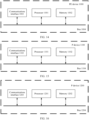
- the SRv6-VPN SID TLV field includes a T field, an L field, a V field, and a reserved (reserved) field. A specific structure may be shown in FIG. 6 .
- the T field is used to indicate a type of a carried SRv6-VPN SID.
- the L field is used to indicate a total length of the V field, and is usually 16 bytes.
- the V field carries specific SRv6-VPN SID information.
- the reserved field should be filled as 0 when the MP-BGP message is sent, and may be ignored when the MP-BGP message is received.
- the reserved field is usually eight bytes.
- a function of the T field may be equivalent to a function of a VPN MPLS label attribute in a route including a multiprotocol label switching (MPLS) label, and may alternatively be equivalent to a function of a VPN MPLS label attribute in a route including an EVPN.
- MPLS multiprotocol label switching
- the first VPN route includes the second SRv6 VPN SID and the third SRv6 VPN SID. Therefore, after the second SRv6 VPN SID is carried in the BGP-Prefix-SID attribute field, a new field further needs to be extended in the BGP-Prefix-SID attribute field to carry the third SRv6 VPN SID.
- a TLV field may be extended to carry the third SRv6 VPN SID.
- a type T field in the TLV field is used to indicate a type of the third SRv6 VPN SID.
- the T field may be used to indicate that the third SRv6 VPN SID is a bypass SRv6 VPN SID, and is used to indicate that when a fault occurs between the first PE and the second CE or a fault occurs in the second CE, the first PE device is instructed to forward a packet through a path between the first PE device and the second PE device.
- the second PE device is configured with the third SRv6 VPN SID.
- a length L field in the TLV field is used to identify a length of the third SRv6 VPN SID, and a value V field in the TLV field is a value of the third SRv6 VPN SID.
- the third SRv6 VPN SID when the third SRv6 VPN SID is carried in the BGP-Prefix-SID attribute field, different types may be set for the second SRv6 VPN SID and the third SRv6 VPN SID. For example, a type of the second SRv6 VPN SID is set to 1, and a type of the third SRv6 VPN SID is set to 2.
- the first PE device may identify a type of an SRv6 VPN SID based on different TLV fields in the BGP-Prefix-SID attribute field, to distinguish between the second SRv6 VPN SID and the third SRv6 VPN SID.
- the third SRv6 VPN SID may be alternatively carried in an NLRI field of the MP-BGP message.
- MP_REACH_NLRI may be understood as multiprotocol extensions attribute information of NLRI, and includes three parts: an address family information field, a next hop information field, and a network layer reachability information (NLRI) field.
- the address family information field includes an address family identifier field (two bytes) and a subsequent address family identifier field (one byte).
- An address family identifier (English: Address Family Identifier, AFI) is used to identify a network layer protocol. For example, if the AFI is set to 1, it indicates IPv4; and if the AFI is set to 2, it indicates IPv6.
- a SAFI identifies a type of a subsequent address family. For example, if the SAFI is set to 1, it indicates unicast; if the SAFI is set to 2, it indicates multicast; and if the SAFI is set to 128, it indicates a VPN.
- an AFI value is 1 and a SAFI value is 1, it indicates that an NLRI field carries an IPv4 unicast route. If the AFI value is 1 and the SAFI value is 128, it indicates that the NLRI field carries a BGP-VPNv4 route. If the AFI value is 1, and the SAFI value is 4, it indicates that the NLRI field carries a BGP label route.
- ABGP synchronized address family may be understood as an extended subsequent address family in an IPv4 address family or an IPv6 address family in an existing BGP protocol.
- the AFI value may be 1 or 2.
- the SAFI value may be determined based on a standard stipulated by the internet engineering task force (English: Internet Engineering Task Force, IETF).
- the next hop information field includes an address length field of a next hop (one byte) and an address field of the next hop (a variable length).
- the address length field of the next hop is used to identify a length of the address field of the next hop, and the length of the address field of the next hop is determined by using the length identified by the address length field of the next hop.
- One-byte reserved field is reserved between the next hop information field and the NLRI field.
- the NLRI field includes the NLRI field.
- the NLRI field may include, for example, a TLV field (a variable length).
- the TLV field may include a T field, an L field, and a V field.
- the T field is used to indicate the type of the carried third SRv6 VPN SID.
- the L field is used to indicate a total length of the carried third SRv6 VPN SID, and is usually 16 bytes.
- the V field carries the third SRv6 VPN SID.
- the first PE device determines that the second SRv6 VPN SID is the same as the first SRv6 VPN SID.
- At least two PE devices in PE devices multi-homed to a CE device are configured with a same SRv6 VPN SID, and the SRv6 VPN SID is used to identify a VPN that is of the PE device and to which the CE belongs or an outgoing interface through which the PE device is connected to the CE device. Therefore, after receiving the first VPN route sent by the second PE device, the first PE device may determine that the second SRv6 VPN SID in the first VPN route is the same as the first SRv6 VPN SID of the first PE device. Therefore, the first PE device may determine that the second PE device is also connected to the second CE device. Further, it may be determined that the second CE device is multi-homed to the first PE device and the second PE device.
- the first PE device establishes a second path from the first PE device to the second PE device based on the third SRv6 VPN SID in the first VPN route.
- the second path is used by the first PE device to forward a packet to the second CE device.
- the first PE device needs to establish a path between the first PE device and the second PE device based on the third SRv6 VPN SID of the second PE device, and the second PE device establishes a path between the second PE device and the first PE device based on the fourth SRv6 VPN SID of the first PE device, so that data may be transmitted between the first PE device and the second PE device.
- the first PE device After determining that the second SRv6 VPN SID is the same as the first SRv6 VPN SID, the first PE device establishes the second path from the first PE device to the second PE device based on the third SRv6 VPN SID in the first VPN route. In this way, when the first PE device sends a packet to the second CE device, if the first path directly connected to the first PE device and the second CE device is faulty, the first PE device may transmit the packet on the second path through switching, so that the second PE device transmits the packet to the second CE device.
- the second PE device is configured with the third SRv6 VPN SID that is different from the second SRv6 VPN SID, so that the first PE device may establish the second path based on the third SRv6 VPN SID.
- the packet transmitted by the first PE device to the second CE device may be transmitted on the second path through switching. Therefore, rapid path switching is implemented, the packet can be transmitted to the second CE device, and multi-homing protection is implemented.
- the first PE device may generate fast reroute (Fast Reroute, FRR) information based on the third SRv6 VPN SID in the first VPN route and a route sent by the second CE device, to implement fast reroute in a process in which the first PE device is transmitting the packet.
- FRR fast reroute
- this embodiment of the present invention may further include the following step: The first PE device sends a second VPN route to the second PE device.
- the second VPN route carries the first SRv6 VPN SID and the fourth SRv6 VPN SID.
- the fourth SRv6 VPN SID is used to identify the VPN to which the second CE device belongs or the outgoing interface through which the first PE is connected to the second CE, and the fourth SRv6 VPN SID is used by the second PE device to establish a third path from the second PE device to the first PE device.
- the third path is used by the second PE device to transmit a packet to the second CE device.
- the fourth SRv6 VPN SID is different from the first SRv6 VPN SID, and the first SRv6 VPN SID is the same as the second SRv6 VPN SID stored in the second PE device.
- the first PE device also needs to send a VPN route, namely, the second VPN route, to the second PE device.
- the second VPN route includes the first SRv6 VPN SID and the fourth SRv6 VPN SID that are configured in the first PE device.
- the second VPN route may also be carried in an MP-BGP message and then sent to the second PE device.
- a manner of carrying the second VPN route is the same as a manner of carrying the first VPN route, and details are not described herein again.
- the second PE device may determine that the first SRv6 VPN SID is the same as the second SRv6 VPN SID. Therefore, it may be determined that the first PE device is also connected to the second CE. Further, it may be determined that the second CE device is multi-homed to the first PE device and the second PE device. Therefore, the second PE device may establish the third path from the second PE device to the first PE device based on the fourth SRv6 VPN SID. In this way, when the second PE device sends a packet to the second CE device, if the fourth path directly connected to the second PE device and the second CE device is faulty, the second PE device may transmit the packet on the third path through switching, so that the first PE device transmits the packet to the second CE device. Therefore, rapid path switching is implemented.
- the first PE device and the second PE device further need to send VPN routes to another PE device (for example, an ingress PE device).
- the first PE device sends a VPN route to another PE device.
- the VPN route sent by the first PE device to the another PE device is the second VPN route, and the second VPN route includes the first SRv6 VPN SID and the fourth SRv6 VPN SID.
- the another PE device may compare the first SRv6 VPN SID with an SRv6 VPN SID configured in the another PE device, to determine whether the first SRv6 VPN SID is the same as the SRv6 VPN SID configured in the another PE device.
- first SRv6 VPN SID is the same as the SRv6 VPN SID configured in the another PE device, a path between the another PE device and the first PE device is established based on the fourth SRv6 VPN SID. If the first SRv6 VPN SID is different from the SRv6 VPN SID configured in the another PE device, a path between the another PE device and the first PE device is established based on the first SRv6 VPN SID.
- the second VPN route sent by the first PE device to the another PE device may also be carried in an MP-BGP message and then sent to the another PE device.
- each device may alternatively advertise a route by using a public network, so that a P device and another device may exchange routing information.
- a data transmission path may be established between devices to transmit data.
- at least two PE devices in PE devices multi-homed to a CE device each are configured with a bypass SRv6 VPN SID, and a path may be established between the at least two PE devices based on the bypass SRv6 VPN SID. Therefore, multi-homing path protection is implemented.
- a process in which the first PE device sends a first packet to the second CE device is used as an example.
- Another non-claimed embodiment of the present invention provides a data transmission method.
- the method is applied to a data forwarding layer of the network based on an SRv6-based VPN, and specifically applied to the data forwarding layer of the network architecture shown in FIG. 2 .
- the method includes the following steps.
- a first PE device receives a first packet.
- the first packet is sent by a first CE device to a second CE device.
- the first CE device sends the first packet to an ingress PE device.
- the first packet includes a source CE address and a destination CE address.
- the source CE address is an address of the first CE device
- the destination CE address is an address of the second CE device.
- the ingress PE device determines, based on the destination CE address and VRF corresponding to the first CE device, a path for transmitting the first packet.
- the ingress PE device sends the first packet to the first PE device by using a first P device, and the first PE device receives the first packet.
- An outer destination address encapsulated in the first packet is a first SRv6 VPN SID.
- the first PE device determines, based on the first SRv6 VPN SID, a first path for transmitting the first packet.
- the first path is directly connected to the first PE device and the second CE device.
- the first PE device may query a corresponding VRF table based on the first SRv6 VPN SID encapsulated in the first packet, to determine a VPN identified by the first SRv6 VPN SID or an outgoing interface connected to the second CE device, and further determine the first path for sending the first packet to the second CE device.
- the first PE device determines to transmit the first packet through the first path directly connected to the first PE device and the second CE device. Therefore, after receiving the first packet, the first PE device may determine the first path directly connected to the first PE device and the second CE device.
- the first PE device determines that the first path is faulty, and the first PE device determines, based on the first SRv6 VPN SID and a stored third SRv6 VPN SID sent by a second PE device, to forward the first packet through a second path.
- the first PE device is connected to the second PE device by using the second path.
- the first PE device When determining the first path, the first PE device also detects whether the first path is faulty, to avoid a case in which the first packet cannot be transmitted to the second CE device due to a fault of the first path.
- a path from the first PE device to the second CE device further includes the second path that is established based on the third SRv6 VPN SID of the second PE device and that is from the first PE device to the second PE device. Therefore, in this case, the first PE device may transmit, through switching, the first packet on the second path that is from the first PE device to the second PE device, and forward the first packet to the second CE device by using the second PE device.
- the first PE device forwards the first packet to the second CE through the second path.
- the first PE device determines that a next hop is the second PE device, and an address of the next hop is the third SRv6 VPN SID of the second PE device. Therefore, the outer destination address encapsulated in the first packet may be changed into the third SRv6 VPN SID, and the encapsulated first packet is sent to the second PE device by using the outgoing interface connected to the second PE device.
- the second PE device decapsulates the first packet, and then sends the first packet to the second CE device.
- the first PE device establishes the second path to the second PE device based on the third SRv6 VPN SID.
- a packet transmitted by the first PE device to the second CE device may be transmitted on the second path through switching. Therefore, rapid path switching and multi-homing protection are implemented, and the packet can be transmitted to the second CE device.
- FIG. 8 is a schematic block diagram of a PE device 500 according to a claimed embodiment of the present invention.
- the PE device 500 is used as a first PE device, and is used in a network that bears an SRv6-based VPN service.
- the network includes a first CE device, a second CE device, an ingress PE device, N egress PE devices, and at least one P device.
- the first CE device is connected to the ingress PE device, and the second CE device is multi-homed to the N egress PE devices.
- the ingress PE device is communicatively connected to the N egress PE devices by using the at least one P device, and the first CE device and the second CE device belong to a same VPN.
- the N egress PE devices include a first PE device and a second PE device.
- the first PE device is configured with a first SRv6 VPN SID, and the first SRv6 VPN SID is used to identify the VPN to which the second CE device belongs or an outgoing interface through which the first PE is connected to the second CE device.
- the second PE device is configured with a second SRv6 VPN SID and a third SRv6 VPN SID, and both the second SRv6 VPN SID and the third SRv6 VPN SID are used to identify the VPN to which the second CE device belongs or an outgoing interface through which the second PE device is connected to the second CE device.
- N is an integer greater than or equal to 2.
- the PE device 500 may include a receiving unit 501 and a processing unit 502.
- the receiving unit 501 is configured to receive a first VPN route sent by the second PE device, and the first VPN route includes the second SRv6 VPN SID and the third SRv6 VPN SID.
- the processing unit 502 is configured to determine that the second SRv6 VPN SID is the same as the first SRv6 VPN SID.
- the processing unit 502 is further configured to establish a second path from the first PE device to the second PE device based on the third SRv6 VPN SID in the first VPN route, and when a first path directly connected to the first PE device and the second CE device is faulty, the second path is used by the first PE device to forward a packet to the second CE device.
- the second SRv6 VPN SID is the same as the first SRv6 VPN SID. Therefore, a path to the first SRv6 VPN SID includes a path to the PE device 500 and a path to the second PE device. Therefore, when a packet sent by the first CE device to the second CE device is transmitted, if a fifth path to the PE device 500 is faulty, a sixth path to the second PE device may be determined. Further, the packet may be transmitted to the second PE device on the sixth path through switching, so that the second PE device may send the packet to the second CE device.
- an ingress PE device may not detect whether an egress PE device on the path is faulty.
- the ingress PE device detects, in a packet transmission process, that the egress PE device is faulty, the packet is transmitted through a path that is to a PE device which has a same SRv6 VPN SID as the egress PE device, so that rapid path switching is implemented. Therefore, BFD does not need to be deployed, between PE devices that establish a path, to detect a fault. To be specific, BFD does not need to be deployed between the ingress PE device and the egress PE device to detect a fault.
- the second PE device is configured with the third SRv6 VPN SID that is different from the first SRv6 VPN SID, so that the PE device 500 may establish the second path based on the third SRv6 VPN SID in the first VPN route.
- a packet transmitted by the PE device 500 to the second CE device may be transmitted on the second path through switching. Therefore, rapid path switching is implemented, the packet can be transmitted to the second CE device, and multi-homing protection is implemented.
- FIG. 9 is another schematic block diagram of the PE device 500 according to an embodiment of the present invention.
- the sending unit 503 is configured to send a second VPN route to the second PE device, and the second VPN route carries the first SRv6 VPN SID and a fourth SRv6 VPN SID.
- the fourth SRv6 VPN SID is used to identify the VPN to which the second CE device belongs or the outgoing interface through which the first PE device is connected to the second CE device, and the fourth SRv6 VPN SID is used by the second PE device to establish a third path from the second PE device to the first PE device.
- the third path is used by the second PE device to transmit a packet to the second CE device.
- the fourth SRv6 VPN SID is different from the first SRv6 VPN SID, and the first SRv6 VPN SID is the same as the second SRv6 VPN SID stored in the second PE device.
- the first VPN route is carried in a BGP-Prefix-SID attribute field of an MP-BGP message
- the BGP-Prefix-SID attribute field includes an SRv6-VPN SID TLV field.
- the SRv6-VPN SID TLV field includes a T field, an L field, and a V field, and the V field is used to carry the third SRv6 VPN SID.
- the receiving unit 501 is further configured to receive a first packet.
- the first packet is sent by the first CE device to the second CE device, and an outer destination address encapsulated in the first packet is the first SRv6 VPN SID.
- the processing unit 502 is further configured to determine that the first path is faulty.
- the processing unit 502 is further configured to determine, based on the first SRv6 VPN SID and the third SRv6 VPN SID, to forward the first packet through the second path.
- the PE device 500 may correspond to an execution body in the route processing method according to the embodiments of the present invention.
- the foregoing and other operations and/or functions of the modules in the PE device 500 are respectively used to implement corresponding procedures of the methods performed by the first PE device in the embodiment shown in FIG. 3 .
- details are not described herein again.
- FIG. 10 is a schematic block diagram of a PE device 600 according to another embodiment of the present invention.
- the PE device 600 is used as a first PE device, and is used in a network that bears an SRv6-based VPN service.
- the network includes a first CE device, a second CE device, an ingress PE device, N egress PE devices, and at least one P device.
- the first CE device is connected to the ingress PE device, and the second CE device is multi-homed to the N egress PE devices.
- the ingress PE device is communicatively connected to the N egress PE devices by using the at least one P device, and the first CE device and the second CE device belong to a same VPN.
- the N egress PE devices include a first PE device and a second PE device.
- the first PE device is configured with a first SRv6 VPN SID, and the first SRv6 VPN SID is used to identify the VPN to which the second CE device belongs or an outgoing interface through which the first PE device is connected to the second CE device.
- the second PE device is configured with a second SRv6 VPN SID and a third SRv6 VPN SID, and both the second SRv6 VPN SID and the third SRv6 VPN SID are used to identify the VPN to which the second CE device belongs or an outgoing interface through which the second PE device is connected to the second CE device.
- the first SRv6 VPN SID is the same as the second SRv6 VPN SID, and N is an integer greater than or equal to 2.
- the PE device 600 may include a receiving unit 601, a processing unit 602, and a sending unit 603.
- the receiving unit 601 is configured to receive a first packet.
- the first packet is sent by the first CE device to the second CE device, and an outer destination address encapsulated in the first packet is the first SRv6 VPN SID.
- the processing unit 602 is configured to determine, based on the first SRv6 VPN SID, a first path for forwarding the first packet, and the first path is directly connected to the first PE device and the second CE device.
- the sending unit 603 is configured to forward the first packet to the second CE through the second path.
- the second SRv6 VPN SID is the same as the first SRv6 VPN SID. Therefore, a path to the first SRv6 VPN SID includes a path to the PE device 600 and a path to the second PE device. Therefore, when a packet sent by the first CE device to the second CE device is transmitted, if a fifth path to the PE device 600 is faulty, a sixth path to the second PE device may be determined. Further, the packet may be transmitted to the second PE device on the sixth path through switching, so that the second PE device may send the packet to the second CE device.
- an ingress PE device may not detect whether an egress PE device on the path is faulty.
- the ingress PE device detects, in a packet transmission process, that the egress PE device is faulty, the packet is transmitted through a path that is to a PE device which has a same SRv6 VPN SID as the egress PE device, so that rapid path switching is implemented. Therefore, BFD does not need to be deployed, between PE devices that establish a path, to detect a fault. To be specific, BFD does not need to be deployed between the ingress PE device and the egress PE device to detect a fault.
- the PE device 600 transmits the first packet to the second CE device.
- a packet may be transmitted on the second path through switching. Therefore, rapid path switching is implemented, the packet can be transmitted to the second CE device, and multi-homing protection is implemented.
- the receiving unit 601 is further configured to receive a first VPN route sent by the second PE device, and the first VPN route includes the second SRv6 VPN SID and the third SRv6 VPN SID.
- the processing unit 602 is further configured to establish the second path based on the third SRv6 VPN SID when determining that the second SRv6 VPN SID is the same as the first SRv6 VPN SID.
- the PE device 600 may correspond to an execution body in the data transmission method according to the embodiments of the present invention.
- the foregoing and other operations and/or functions of the modules in the PE device 600 are respectively used to implement corresponding procedures of the methods performed by the first PE device in the embodiment shown in FIG. 4 .
- details are not described herein again.
- FIG. 11 is a schematic block diagram of a P device 700 according to a non-claimed embodiment of the present invention.
- the P device 700 is used as a first P device, and is used in a network that bears an SRv6-based VPN service.
- the network includes a first CE device, a second CE device, an ingress PE device, N egress PE devices, and at least one P device.
- the first CE device is connected to the ingress PE device, and the second CE device is multi-homed to the N egress PE devices.
- the ingress PE device is communicatively connected to the N egress PE devices by using the at least one P device, and the first CE device and the second CE device belong to a same VPN.
- the N egress PE devices include a first PE device and a second PE device.
- the first PE device is configured with a first SRv6 VPN SID, and the first SRv6 VPN SID is used to identify the VPN to which the second CE device belongs or an outgoing interface through which the first PE is connected to the second CE device.
- the second PE device is configured with a second SRv6 VPN SID, and the second SRv6 VPN SID is used to identify the VPN to which the second CE device belongs or an outgoing interface through which the second PE device is connected to the second CE device.
- the first SRv6 VPN SID is the same as the second SRv6 VPN SID.
- the at least one P device includes the first P device, the first P device is a neighboring node of the first PE device, and the first PE device is a next hop of the first P device.
- N is an integer greater than or equal to 2.
- the P device 700 may include a receiving unit 701 and a processing unit 702.
- the receiving unit 701 is configured to receive a first route sent by the first PE device, and the first route includes a network segment to which the first SRv6 VPN SID belongs.
- the receiving unit 701 is further configured to receive a second route sent by the second PE device, and the second route includes a network segment to which the second SRv6 VPN SID belongs.
- the processing unit 702 is configured to establish a fifth path from the first P device to the first PE device based on the network segment to which the first SRv6 VPN SID belongs, and the fifth path is used by the first P device to forward a packet to the second CE device.
- the processing unit 702 is further configured to establish a sixth path from the first P device to the second PE device based on the network segment to which the second SRv6 VPN SID belongs, and when the fifth path is faulty, the sixth path is used by the first P device to forward the packet to the second CE device.
- the second SRv6 VPN SID is the same as the first SRv6 VPN SID, and the network segment to which the second SRv6 VPN SID belongs is also the same as the network segment to which the first SRv6 VPN SID belongs. Therefore, a path from the P device 700 to the first SRv6 VPN SID includes a path to the first PE device and a path to the second PE device.
- the P device 700 may determine the sixth path to the second PE device, and further transmit the packet to the second PE device on the sixth path through switching, so that the second PE device may send the packet to the second CE device.
- an ingress PE device may not detect whether an egress PE device on the path is faulty.
- the packet When the ingress PE device detects, in a packet transmission process, that the egress PE device is faulty, the packet is transmitted through a path that is to a PE device which has a same SRv6 VPN SID as the egress PE device, so that rapid path switching is implemented. Therefore, BFD does not need to be deployed, between PE devices that establish a path, to detect a fault. To be specific, BFD does not need to be deployed between the ingress PE device and the egress PE device to detect a fault. Therefore, an amount of BFD deployed in a PE device is reduced, resources that are of the PE device and that are occupied by the BFD is reduced, time for fault detection is reduced when the PE device determines a path, and a path switching speed is increased.
- the receiving unit 701 is further configured to receive a first packet.
- the first packet is sent by the first CE device to the second CE device, and an outer destination address encapsulated in the first packet is the first SRv6 VPN SID.
- the processing unit 702 is further configured to determine, based on the first SRv6 VPN SID when the fifth path is faulty, to forward the first packet through the sixth path.
- the P device 700 may correspond to an execution body in the route processing method according to the embodiments of the present invention.
- the foregoing and other operations and/or functions of the modules in the P device 700 are respectively used to implement corresponding procedures of the methods performed by the first P device in the embodiment shown in FIG. 5 .
- details are not described herein again.
- FIG. 12 is a schematic block diagram of a P device 800 according to another non-claimed embodiment of the present invention.
- the P device 800 is used as a first P device, and is used in a network that bears an SRv6-based VPN service.
- the SRv6-based VPN includes a first customer edge CE device, a second CE device, an ingress PE device, N egress PE devices, and at least one P device.
- the first CE device is connected to the ingress PE device, and the second CE device is multi-homed to the N egress PE devices.
- the ingress PE device is communicatively connected to the N egress PE devices by using the at least one P device, and the first CE device and the second CE device belong to a same VPN.
- the N egress PE devices include a first PE device and a second PE device.
- the first PE device is configured with a first SRv6 VPN SID, and the first SRv6 VPN SID is used to identify the VPN to which the second CE device belongs or an outgoing interface through which the first PE is connected to the second CE device.
- the second PE device is configured with a second SRv6 VPN SID, and the second SRv6 VPN SID is used to identify the VPN to which the second CE device belongs or an outgoing interface through which the second PE device is connected to the second CE device.
- the first SRv6 VPN SID is the same as the second SRv6 VPN SID.
- the at least one P device includes the first P device, the first P device is a neighboring node of the first PE device, and the first PE device is a next hop of the first P device.
- N is an integer greater than or equal to 2.
- the P device 800 may include a receiving unit 801, a processing unit 802, and a sending unit 803.
- the receiving unit 801 is configured to receive a first packet.
- the first packet is sent by the first CE device to the second CE device, and an outer destination address encapsulated in the first packet is the first SRv6 VPN SID.
- the processing unit 802 is configured to determine, based on the first SRv6 VPN SID, a fifth path for transmitting the first packet, and the first P device is connected to the first PE device by using the fifth path.
- the processing unit 802 is further configured to determine that the fifth path is faulty.
- the first P device determines, based on the first SRv6 VPN SID, to forward the first packet through a sixth path, and the first P device is connected to the second PE by using the sixth path.
- the sending unit 803 is configured to forward the first packet to the second CE device through the sixth path.
- the second SRv6 VPN SID is the same as the first SRv6 VPN SID. Therefore, a path from the P device 800 to the first SRv6 VPN SID includes a path to the first PE device and a path to the second PE device. Therefore, when a packet sent by the first CE device to the second CE device is transmitted by the P device 800, if the fifth path to the first PE is faulty, the P device 800 may determine the sixth path to the second PE device, and further transmit the packet to the second PE device on the sixth path through switching, so that the second PE device may send the packet to the second CE device.
- an ingress PE device may not detect whether an egress PE device on the path is faulty.
- the ingress PE device detects, in a packet transmission process, that the egress PE device is faulty, the packet is transmitted through a path that is to a PE device which has a same SRv6 VPN SID as the egress PE device, so that rapid path switching is implemented. Therefore, BFD does not need to be deployed, between PE devices that establish a path, to detect a fault. To be specific, BFD does not need to be deployed between the ingress PE device and the egress PE device to detect a fault. Therefore, an amount of BFD deployed in a PE device is reduced, resources that are of the PE device and that are occupied by the BFD is reduced, time for fault detection is reduced when the PE device determines a path, and a path switching speed is increased.
- the receiving unit 801 is further configured to receive a first route sent by the first PE device, and the first route includes a network segment to which the first SRv6 VPN SID belongs.
- the receiving unit 801 is further configured to receive a second route sent by the second PE device, and the second route includes a network segment to which the second SRv6 VPN SID belongs.
- the processing unit 802 is further configured to establish the fifth path based on the network segment to which the first SRv6 VPN SID belongs and the sixth path based on the network segment to which the second SRv6 VPN SID belongs.
- the sixth path is used by the first P device to forward a packet to the second CE device.
- the P device 800 may correspond to an execution body in the data transmission method according to the embodiments of the present invention.
- the foregoing and other operations and/or functions of the modules in the P device 800 are respectively used to implement corresponding procedures of the methods performed by the first PE device in the embodiment shown in FIG. 7 .
- details are not described herein again.
- FIG. 13 is a schematic structural diagram of another PE device 900 according to a non-claimed embodiment of the present invention. As shown in FIG. 13 , the PE device 900 includes a processor 901, a memory 902, and a communications interface 903.
- the processor 901 may be a central processing unit (CPU), a network processor (NP), or a combination of a CPU and an NP.
- the processor 301 may further include a hardware chip.
- the hardware chip may be an application-specific integrated circuit (ASIC), a programmable logic device (PLD), or a combination thereof.
- the PLD may be a complex programmable logic device (CPLD), a field programmable logic gate array (FPGA), generic array logic (GAL), or any combination thereof.
- the memory 902 may be a separate device, or may be integrated into the processor 901.
- the memory 902 may include a volatile memory, for example, a random access memory (RAM); or the memory may include a nonvolatile memory, for example, a flash memory, a hard disk (HDD), or a solid-state drive (SSD); or the memory 902 may include a combination of the foregoing types of memories.
- RAM random access memory
- HDD hard disk
- SSD solid-state drive
- the communications interface 903 is configured to communicate with an external device, and the communications interface 903 may be a wireless interface or a wired interface.
- the wireless interface may be a cellular mobile network interface, a wireless local area network interface, or the like.
- the wired interface may be an ethernet interface, for example, an optical interface or an electrical interface.
- the PE device 900 may further include a bus 904.
- the bus 904 is configured to connect the processor 901, the memory 902, and the communications interface 903, so that the processor 901, the memory 902, and the communications interface 903 communicate with each other by using the bus 904.
- the bus 904 may be classified into an address bus, a data bus, a control bus, and the like. For ease of representation, only one thick line is used to represent the bus in FIG. 13 , but this does not mean that there is only one bus or only one type of bus.
- the PE device 900 is configured to implement the corresponding procedures performed by the first PE device in the route processing method in the embodiment of the present invention shown in FIG. 3 . For brevity, details are not described herein again.
- the memory 902 may be further configured to store a program instruction.
- the processor 901 invokes the program instruction stored in the memory 902, and may perform one or more steps in the method shown in FIG. 3 , or an optional implementation thereof.
- the processor 901 is configured to perform all operations of the processing unit 502 of the PE device 500 shown in FIG. 8 or FIG. 9
- the communications interface 903 may be configured to perform all operations of the receiving unit 501 of the PE device 500 shown in FIG. 8 or FIG. 9 and the sending unit 503 shown in FIG. 9 .
- FIG. 14 is a schematic structural diagram of still another PE device 1000 according to a non-claimed embodiment of the present invention. As shown in FIG. 14 , the PE device 1000 includes a processor 1001, a memory 1002, and a communications interface 1003.
- the processor 1001 may be a CPU, a network processor, or a combination of a CPU and an NP.
- the processor 1001 may further include a hardware chip.
- the hardware chip may be an ASIC, a PLD, or a combination thereof.
- the PLD may be a CPLD, an FPGA, generic array logic, or any combination thereof.
- the memory 1002 may be a separate device, or may be integrated into the processor 1001.
- the memory 1002 may include a volatile memory, such as a RAM; or the memory may include a nonvolatile memory, such as a flash memory, a hard disk, or a solid-state drive; or the memory 1002 may include a combination of the foregoing types of memories.
- the communications interface 1003 is configured to communicate with an external device, and the communications interface 1003 may be a wireless interface or a wired interface.
- the wireless interface may be a cellular mobile network interface, a wireless local area network interface, or the like.
- the wired interface may be an ethernet interface, for example, an optical interface or an electrical interface.
- the PE device 1000 may further include a bus 1004.
- the bus 1004 is configured to connect the processor 1001, the memory 1002, and the communications interface 1003, so that the processor 1001, the memory 1002, and the communications interface 1003 communicate with each other by using the bus 1004.
- the bus 1004 may be classified into an address bus, a data bus, a control bus, and the like. For ease of representation, only one thick line is used to represent the bus in FIG. 14 , but this does not mean that there is only one bus or only one type of bus.
- the PE device 1000 is configured to implement the corresponding procedures performed by the first PE device in the data transmission method in the embodiment of the present invention shown in FIG. 4 . For brevity, details are not described herein again.
- the memory 1002 may be further configured to store a program instruction.
- the processor 1001 invokes the program instruction stored in the memory 1002, and may perform one or more steps in the method shown in FIG. 4 , or an optional implementation thereof.
- the processor 1001 is configured to perform all operations of the processing unit 602 of the PE device 600 shown in FIG. 10
- the communications interface 1003 may be configured to perform all operations of the receiving unit 601 and the sending unit 603 of the PE device 600 shown in FIG. 10 .
- FIG. 15 is a schematic structural diagram of another P device 1100 according to a non-claimed embodiment of the present invention. As shown in FIG. 15 , the P device 1100 includes a processor 1101, a memory 1102, and a communications interface 1103.
- the processor 1101 may be a CPU, a network processor, or a combination of a CPU and an NP.
- the processor 1101 may further include a hardware chip.
- the hardware chip may be an ASIC, a PLD, or a combination thereof.
- the PLD may be a CPLD, an FPGA, a GAL, or any combination thereof.
- the memory 1102 may be a separate device, or may be integrated into the processor 1101.
- the memory 1102 may include a volatile memory, such as a RAM; or the memory may include a nonvolatile memory, such as a flash memory, a hard disk, or a solid-state drive; or the memory 1102 may include a combination of the foregoing types of memories.
- the communications interface 1103 is configured to communicate with an external device, and the communications interface 1103 may be a wireless interface or a wired interface.
- the wireless interface may be a cellular mobile network interface, a wireless local area network interface, or the like.
- the wired interface may be an ethernet interface, for example, an optical interface or an electrical interface.
- the P device 1100 may further include a bus 1104.
- the bus 1104 is configured to connect the processor 1101, the memory 1102, and the communications interface 1103, so that the processor 1101, the memory 1102, and the communications interface 1103 communicate with each other by using the bus 1104.
- the bus 1104 may be classified into an address bus, a data bus, a control bus, and the like. For ease of representation, only one thick line is used to represent the bus in FIG. 15 , but this does not mean that there is only one bus or only one type of bus.
- the P device 1100 is configured to implement the corresponding procedures performed by the first P device in the route processing method in the embodiment of the present invention shown in FIG. 5 . For brevity, details are not described herein again.
- the memory 1102 may be further configured to store a program instruction.
- the processor 1101 invokes the program instruction stored in the memory 1102, and may perform one or more steps in the method shown in FIG. 5 , or an optional implementation thereof.
- the processor 1101 is configured to perform all operations of the processing unit 702 of the P device 700 shown in FIG. 11
- the communications interface 1103 may be configured to perform all operations of the receiving unit 701 of the P device 700 shown in FIG. 11 .
- FIG. 16 is a schematic structural diagram of another P device 1200 according to a non-claimed embodiment of the present invention. As shown in FIG. 16 , the P device 1200 includes a processor 1201, a memory 1202, and a communications interface 1203.
- the processor 1201 may be a CPU, a network processor, or a combination of a CPU and an NP.
- the processor 1201 may further include a hardware chip.
- the hardware chip may be an ASIC, a PLD, or a combination thereof.
- the PLD may be a CPLD, a field programmable gate array FPGA, generic array logic, or any combination thereof.
- the memory 1202 may be a separate device, or may be integrated into the processor 1201.
- the memory 1202 may include a volatile memory, such as a random access memory RAM; or the memory may include a nonvolatile memory, such as a flash memory, a hard disk, or a solid-state drive; or the memory 1202 may include a combination of the foregoing types of memories.
- the communications interface 1203 is configured to communicate with an external device, and the communications interface 1203 may be a wireless interface or a wired interface.
- the wireless interface may be a cellular mobile network interface, a wireless local area network interface, or the like.
- the wired interface may be an ethernet interface, for example, an optical interface or an electrical interface.
- the P device 1200 may further include a bus 1204.
- the bus 1204 is configured to connect the processor 1201, the memory 1202, and the communications interface 1203, so that the processor 1201, the memory 1202, and the communications interface 1203 communicate with each other by using the bus 1204.
- the bus 1204 may be classified into an address bus, a data bus, a control bus, and the like. For ease of representation, only one thick line is used to represent the bus in FIG. 16 , but this does not mean that there is only one bus or only one type of bus.
- the P device 1200 is configured to implement the corresponding procedures performed by the first P device in the route processing method in the embodiment of the present invention shown in FIG. 7 . For brevity, details are not described herein again.
- the memory 1202 may be further configured to store a program instruction.
- the processor 1201 invokes the program instruction stored in the memory 1202, and may perform one or more steps in the method shown in FIG. 7 , or an optional implementation thereof.
- the processor 1201 is configured to perform all operations of the processing unit 802 of the P device 800 shown in FIG. 12
- the communications interface 1203 may be configured to perform all operations of the receiving unit 801 and the sending unit 803 of the P device 800 shown in FIG. 12 .
- a non-claimed embodiment of the present invention further provides a communications system, including the PE device 500 shown in FIG. 8 or FIG. 9 and the P device 700 shown in FIG. 11 .
- a non-claimed embodiment of the present invention further provides another communications system, including the PE device 500 shown in FIG. 8 or FIG. 9 and the P device 700 shown in FIG. 12 .
- a non-claimed embodiment of the present invention further provides still another communications system, including the PE device 600 shown in FIG. 10 and the P device 800 shown in FIG. 11 .
- a non-claimed embodiment of the present invention further provides yet another communications system, including the PE device 600 shown in FIG. 10 and the P device 800 shown in FIG. 12 .
- All or some of the foregoing embodiments may be implemented by using software, hardware, firmware, or any combination thereof.
- software is used to implement the embodiments, all or some of the embodiments may be implemented in a form of a computer program product.
- the computer program product includes one or more computer instructions.
- the computer program instruction is loaded and executed on a computer, the procedure or functions according to the embodiments of the present invention are all or partially generated.
- the computer may be a general-purpose computer, a special-purpose computer, a computer network, or another programmable apparatus.
- the computer instruction may be stored in a computer readable storage medium or may be transmitted from a computer readable storage medium to another computer readable storage medium.
- the computer instruction may be transmitted from a website, computer, server, or data center to another website, computer, server, or data center in a wired (for example, a coaxial cable, an optical fiber, or a digital subscriber line (DSL)) or wireless (for example, infrared, radio, and microwave) manner.
- the computer readable storage medium may be any usable medium accessible by a computer, or a data storage device, such as a server or a data center, integrating one or more usable media.
- the usable medium may be a magnetic medium (for example, a floppy disk, a hard disk, or a magnetic tape), an optical medium (for example, a DVD), a semiconductor medium (for example, a solid-state drive), or the like.
- sequence numbers of the foregoing processes do not mean execution sequences in the embodiments of the present invention.
- the execution sequences of the processes should be determined based on functions and internal logic of the processes, and should not constitute any limitation on the implementation processes of the embodiments of the present invention.
- the disclosed system, apparatus, and method may be implemented in another manner.
- the described apparatus embodiments are merely examples.
- the unit division is merely logical function division and may be other division in actual implementation.
- a plurality of units or components may be combined or integrated into another system, or some features may be ignored or not performed.
- the displayed or discussed mutual couplings or direct couplings or communication connections may be implemented by using some interfaces.
- the indirect couplings or communication connections between the apparatuses or units may be implemented in electronic, mechanical, or another form.
- the units described as separate parts may or may not be physically separate, and parts displayed as units may or may not be physical units, may be located in one position, or may be distributed on a plurality of network units. Some or all of the units may be selected based on actual requirements to achieve the objectives of the solutions of the embodiments.
- functional units in the embodiments of the present invention may be integrated into one processing unit, or each of the units may exist alone physically, or two or more units are integrated into one unit.
Landscapes
- Engineering & Computer Science (AREA)
- Computer Networks & Wireless Communication (AREA)
- Signal Processing (AREA)
- Computer Security & Cryptography (AREA)
- Computer Hardware Design (AREA)
- Computing Systems (AREA)
- General Engineering & Computer Science (AREA)
- Data Exchanges In Wide-Area Networks (AREA)
Claims (10)
- Procédé de traitement de route, et le procédé comprend :la réception, par un premier dispositif d'extrémité fournisseur, PE, d'une première route de réseau privé virtuel, VPN, envoyée par un second dispositif PE, dans lequel la première route VPN comprend un deuxième identifiant de segment de réseau privé virtuel basé sur le routage de segment de protocole Internet version 6, SRv6 VPN SID, et un troisième SRv6 VPN SID, dans lequel un second dispositif d'extrémité client, CE, est multiconnecté au premier dispositif PE et au second dispositif PE, le premier dispositif PE est configuré avec un premier SRv6 VPN SID utilisé pour identifier un VPN auquel le second dispositif CE appartient ou une interface de sortie par laquelle le premier PE est connecté au second dispositif CE, le second dispositif PE est configuré avec le deuxième SRv6 VPN SID et le troisième SRv6 VPN SID, à la fois le deuxième SRv6 VPN SID et le troisième SRv6 VPN SID sont utilisés pour identifier le VPN auquel le second dispositif CE appartient ou une interface de sortie par laquelle le second dispositif PE est connecté au second dispositif CE, le deuxième SRv6 VPN SID est identique au premier SRv6 VPN SID ; etl'établissement, par le premier dispositif PE, d'un second chemin allant du premier dispositif PE au second dispositif PE sur la base du troisième SRv6 VPN SID, dans lequel, lorsqu'un premier chemin sur lequel le premier dispositif PE est directement connecté au second dispositif CE est défectueux, le second chemin est utilisé par le premier dispositif PE pour acheminer un paquet vers le second dispositif CE.
- Procédé selon la revendication 1, dans lequel le procédé comprend en outre :
l'envoi, par le premier dispositif PE, d'une seconde route VPN au second dispositif PE, dans lequel la seconde route VPN transporte le premier SRv6 VPN SID et un quatrième SRv6 VPN SID, le quatrième SRv6 VPN SID est utilisé pour identifier le VPN auquel le second dispositif CE appartient ou l'interface de sortie par laquelle le premier dispositif PE est connecté au second dispositif CE, le quatrième SRv6 VPN SID est différent du premier SRv6 VPN SID. - Procédé selon la revendication 1 ou 2, dans lequel la première route VPN est transportée dans un champ d'attribut d'identifiant de segment de préfixe de protocole de passerelle frontière, BGP-Prefix-SID, d'un message d'extension multiprotocole pour le protocole de passerelle frontière, MP-BGP.
- Procédé selon l'une quelconque des revendications 1 à 3, dans lequel le procédé comprend en outre :la réception, par le premier dispositif PE, d'un premier paquet, dans lequel le premier paquet est envoyé par un premier dispositif CE au second dispositif CE, et une adresse de destination extérieure encapsulée dans le premier paquet est le premier SRv6 VPN SID ; le fait de déterminer, par le premier dispositif PE, que le premier chemin est défectueux ; eten réponse au fait de déterminer que le premier chemin est défectueux,l'acheminement, par le premier dispositif PE sur la base du premier SRv6 VPN SID et du troisième SRv6 VPN SID, du premier paquet par le second chemin.
- Premier dispositif d'extrémité fournisseur, PE, qui comprend :une unité de réception, configurée pour recevoir une première route de réseau privé virtuel, VPN, envoyée par un second dispositif PE, dans lequel la première route VPN comprend un deuxième identifiant de segment de réseau privé virtuel basé sur le routage de segment de protocole Internet version 6, SRv6 VPN SID, et un troisième SRv6 VPN SID, dans lequel un second dispositif d'extrémité client, CE, est multiconnecté au premier dispositif PE et au second dispositif PE, le premier dispositif PE est configuré avec un premier SRv6 VPN SID utilisé pour identifier un VPN auquel le second dispositif CE appartient ou une interface de sortie par laquelle le premier PE est connecté au second dispositif CE, le second dispositif PE est configuré avec le deuxième SRv6 VPN SID et le troisième SRv6 VPN SID, à la fois le deuxième SRv6 VPN SID et le troisième SRv6 VPN SID sont utilisés pour identifier le VPN auquel le second dispositif CE appartient ou une interface de sortie par laquelle le second dispositif PE est connecté au second dispositif CE, le deuxième SRv6 VPN SID est identique au premier SRv6 VPN SID ;une unité de traitement, configurée pour établir un second chemin allant du premier dispositif PE au second dispositif PE sur la base du troisième SRv6 VPN SID, dans lequel, lorsqu'un premier chemin directement connecté au premier dispositif PE et au second dispositif CE est défectueux, le second chemin est utilisé par le premier dispositif PE pour acheminer un paquet vers le second dispositif CE.
- Dispositif PE selon la revendication 5, comprenant en outre :
une unité d'envoi, configurée pour envoyer une seconde route VPN au second dispositif PE, dans lequel la seconde route VPN transporte le premier SRv6 VPN SID et un quatrième SRv6 VPN SID, le quatrième SRv6 VPN SID est utilisé pour identifier le VPN auquel le second dispositif CE appartient ou l'interface de sortie par laquelle le premier dispositif PE est connecté au second dispositif CE, le quatrième SRv6 VPN SID est différent du premier SRv6 VPN SID. - Dispositif PE selon la revendication 5 ou 6, dans lequel la première route VPN est transportée dans un champ d'attribut d'identifiant de segment de préfixe de protocole de passerelle frontière, BGP-Prefix-SID, d'un message d'extension multiprotocole pour le protocole de passerelle frontière, MP-BGP.
- Dispositif PE selon l'une quelconque des revendications 5 à 7, dans lequel l'unité de réception est en outre configurée pour recevoir un premier paquet, le premier paquet est envoyé au second dispositif CE, et une adresse de destination extérieure encapsulée dans le premier paquet est le premier SRv6 VPN SID ; et l'unité de traitement est en outre configurée pour déterminer que le premier chemin est défectueux ;
en réponse au fait de déterminer que le premier chemin est défectueux, l'unité de traitement est en outre configurée pour acheminer, sur la base du premier SRv6 VPN SID et du troisième SRv6 VPN SID, le premier paquet par le second chemin. - Système, comprenant un premier dispositif d'extrémité fournisseur, PE, un second dispositif PE, et un dispositif d'extrémité client, CE, multiconnecté au premier dispositif PE et au second dispositif PE, dans lequel le premier dispositif PE est le dispositif selon l'une quelconque des revendications 5 à 8.
- Produit-programme informatique, dans lequel comprenant des instructions qui, lorsqu'elles sont exécutées par un processeur, un procédé selon l'une quelconque des revendications 1 à 4 est mis en oeuvre.
Applications Claiming Priority (2)
| Application Number | Priority Date | Filing Date | Title |
|---|---|---|---|
| CN201711258440.7A CN109873760B (zh) | 2017-12-01 | 2017-12-01 | 处理路由的方法和装置、以及数据传输的方法和装置 |
| PCT/CN2018/100443 WO2019105066A1 (fr) | 2017-12-01 | 2018-08-14 | Procédé et appareil de traitement de route, et appareil et procédé de transmission de données |
Publications (3)
| Publication Number | Publication Date |
|---|---|
| EP3713162A1 EP3713162A1 (fr) | 2020-09-23 |
| EP3713162A4 EP3713162A4 (fr) | 2020-11-25 |
| EP3713162B1 true EP3713162B1 (fr) | 2025-01-29 |
Family
ID=66665125
Family Applications (1)
| Application Number | Title | Priority Date | Filing Date |
|---|---|---|---|
| EP18883637.3A Active EP3713162B1 (fr) | 2017-12-01 | 2018-08-14 | Procédé et appareil de traitement de route |
Country Status (4)
| Country | Link |
|---|---|
| US (1) | US11533249B2 (fr) |
| EP (1) | EP3713162B1 (fr) |
| CN (2) | CN111901235B (fr) |
| WO (1) | WO2019105066A1 (fr) |
Families Citing this family (56)
| Publication number | Priority date | Publication date | Assignee | Title |
|---|---|---|---|---|
| CN111837368B (zh) | 2018-02-23 | 2022-01-14 | 华为技术有限公司 | 使用内部网关协议通告和编程优选路径路由 |
| WO2019209480A1 (fr) | 2018-04-26 | 2019-10-31 | Futurewei Technologies, Inc. | Réservation et maintenance de ressources pour des itinéraires de trajet préférés dans un réseau |
| WO2019210769A1 (fr) * | 2018-05-03 | 2019-11-07 | Huawei Technologies Co., Ltd. | Routage explicite avec codage de fonction de réseau |
| CN111510388B (zh) * | 2019-01-30 | 2022-01-21 | 华为技术有限公司 | 一种确定转发路径的方法、装置及系统 |
| CN111698152B (zh) * | 2019-03-15 | 2021-09-14 | 华为技术有限公司 | 一种故障保护方法、节点及存储介质 |
| CN109921898A (zh) * | 2019-03-28 | 2019-06-21 | 新华三技术有限公司 | IPv6无状态地址生成方法及装置 |
| US11595441B2 (en) | 2019-04-04 | 2023-02-28 | Cisco Technology, Inc. | Systems and methods for securing network paths |
| US11411948B2 (en) | 2019-04-04 | 2022-08-09 | Cisco Technology, Inc. | Systems and methods for applying attestation tokens to LISP messages |
| US11863522B2 (en) | 2019-04-04 | 2024-01-02 | Cisco Technology, Inc. | Applying attestation to the border gateway protocol (BGP) |
| US12149626B1 (en) | 2019-04-04 | 2024-11-19 | Cisco Technology, Inc. | Applying attestation to BGP-LS |
| US11356361B2 (en) * | 2019-04-04 | 2022-06-07 | Cisco Technology, Inc. | Systems and methods for steering traffic into SR-TE policies |
| CN110266587B (zh) * | 2019-08-14 | 2019-12-13 | 华为技术有限公司 | 一种链路状态信息的处理方法及装置 |
| US11140074B2 (en) | 2019-09-24 | 2021-10-05 | Cisco Technology, Inc. | Communicating packets across multi-domain networks using compact forwarding instructions |
| CN112636935B (zh) * | 2019-10-08 | 2023-06-30 | 中兴通讯股份有限公司 | 基于IPv6网络的虚拟专用网络组播方法及电子设备 |
| CN112737949B (zh) * | 2019-10-14 | 2023-06-30 | 中兴通讯股份有限公司 | 故障检测方法及装置、电子设备、计算机可读介质 |
| CN112702773B (zh) | 2019-10-22 | 2023-03-03 | 华为技术有限公司 | 一种通信方法及装置 |
| CN112751766B (zh) * | 2019-10-30 | 2023-07-11 | 华为技术有限公司 | 报文转发方法和系统、相关设备和芯片 |
| CN114844828A (zh) | 2019-10-31 | 2022-08-02 | 华为技术有限公司 | 发送报文的方法、装置及系统 |
| CN112787931B (zh) * | 2019-11-06 | 2022-09-23 | 华为技术有限公司 | 报文传输方法、代理节点及存储介质 |
| CN110891022B (zh) * | 2019-11-20 | 2021-11-16 | Ut斯达康通讯有限公司 | 基于SRv6的虚拟子网标识符发布方法和装置 |
| CN112995024B (zh) * | 2019-12-02 | 2024-11-01 | 中兴通讯股份有限公司 | 信号劣化告警方法、系统、终端设备及存储介质 |
| CN112929261B (zh) * | 2019-12-05 | 2024-03-12 | 中兴通讯股份有限公司 | 分段路由隧道的防断纤方法、装置,入口节点及存储介质 |
| CN110958181B (zh) * | 2019-12-06 | 2021-08-17 | Ut斯达康通讯有限公司 | ISIS协议发布跨SRv6的切片网络的方法及装置 |
| CN113132220B (zh) | 2019-12-31 | 2022-12-06 | 华为技术有限公司 | 一种路由信息的处理方法及装置 |
| CN113132221A (zh) | 2019-12-31 | 2021-07-16 | 华为技术有限公司 | 一种路由信息的处理方法及装置 |
| CN113079089B (zh) | 2020-01-03 | 2025-01-07 | 华为技术有限公司 | 业务链的故障保护方法、装置、设备、系统及存储介质 |
| US11438259B2 (en) * | 2020-02-18 | 2022-09-06 | Juniper Networks, Inc. | Flexible algorithm aware border gateway protocol (BGP) prefix segment routing identifiers (SIDs) |
| US11456955B2 (en) * | 2020-04-16 | 2022-09-27 | Juniper Networks, Inc. | Tenant-based mapping for virtual routing and forwarding |
| CN115733793A (zh) * | 2020-04-20 | 2023-03-03 | 华为技术有限公司 | 路由配置方法和路由配置装置 |
| US11516112B2 (en) * | 2020-10-20 | 2022-11-29 | Ciena Corporation | Optimized layer 3 VPN control plane using segment routing |
| CN112511418B (zh) * | 2020-06-22 | 2025-04-29 | 中兴通讯股份有限公司 | 报文指示方法、装置、设备和存储介质 |
| US12348361B2 (en) * | 2020-06-30 | 2025-07-01 | New H3C Technologies Co., Ltd. | Method and apparatus for failure detection and PE device |
| CN111885630B (zh) * | 2020-07-01 | 2023-06-30 | 中国联合网络通信集团有限公司 | 数据传输方法及通信装置 |
| CN119996161B (zh) * | 2020-09-21 | 2025-12-09 | 华为技术有限公司 | 一种实现业务路径检测的方法、设备和系统 |
| CN114363231B (zh) * | 2020-09-28 | 2024-06-18 | 中国移动通信有限公司研究院 | 一种切换下行流量的方法、装置和计算机可读存储介质 |
| US11743180B2 (en) * | 2020-11-20 | 2023-08-29 | At&T Intellectual Property I, L.P. | System and method for routing traffic onto an MPLS network |
| CN116846807A (zh) | 2020-11-27 | 2023-10-03 | 华为技术有限公司 | 通信方法及装置 |
| CN112491926A (zh) * | 2020-12-11 | 2021-03-12 | 迈普通信技术股份有限公司 | SRv6路径质量测量方法、装置、电子设备及存储介质 |
| CN114760243B (zh) * | 2020-12-25 | 2025-08-08 | 华为技术有限公司 | 报文传输方法、设备及系统 |
| CN114844817B (zh) * | 2021-02-02 | 2025-05-30 | 华为技术有限公司 | 一种在段路由sr网络中进行保护倒换方法及装置 |
| CN112822100B (zh) * | 2021-02-05 | 2026-04-28 | 中兴通讯股份有限公司 | 故障保护方法及装置、存储介质、电子装置 |
| US11088996B1 (en) * | 2021-02-10 | 2021-08-10 | SecureCo, Inc. | Secure network protocol and transit system to protect communications deliverability and attribution |
| US20220286395A1 (en) * | 2021-03-07 | 2022-09-08 | Cisco Technology, Inc., A California Corporation | SRv6 Segment Identifiers and Micro Segments Invoking Network Behavior including Realization of Network Slices |
| CN113328937B (zh) * | 2021-04-08 | 2022-05-24 | 新华三技术有限公司 | 分布式聚合的实现方法及装置 |
| CN115225452A (zh) * | 2021-04-19 | 2022-10-21 | 华为技术有限公司 | 转发路径的故障感知方法、装置及系统 |
| CN113452606B (zh) * | 2021-05-18 | 2023-12-26 | 新华三信息安全技术有限公司 | 通信方法及装置 |
| CN113438158B (zh) * | 2021-06-30 | 2022-06-21 | 新华三信息安全技术有限公司 | 一种报文转发方法及装置 |
| CN115622915A (zh) * | 2021-07-16 | 2023-01-17 | 华为技术有限公司 | 一种故障检测的方法、装置和系统 |
| CN113810276B (zh) * | 2021-08-31 | 2024-06-18 | 锐捷网络股份有限公司 | 一种段路由故障处理方法、装置、电子设备及存储介质 |
| CN113992558B (zh) * | 2021-10-26 | 2023-04-18 | 新华三信息安全技术有限公司 | 路由发布的方法、装置、电子设备及介质 |
| CN116266822B (zh) * | 2021-12-16 | 2025-06-10 | 中国电信股份有限公司 | 报文转发方法及装置、存储介质、电子设备 |
| CN114143380B (zh) * | 2022-01-04 | 2023-06-09 | 烽火通信科技股份有限公司 | 解决SRv6尾节点掉电场景OAM和业务不一致的方法和系统 |
| CN114389996B (zh) * | 2022-01-04 | 2023-06-09 | 烽火通信科技股份有限公司 | 一种基于资源的多拓扑环境下SRv6 SID分配的方法及装置 |
| CN118251871A (zh) * | 2022-10-24 | 2024-06-25 | 新华三技术有限公司 | 一种节点保护方法、装置、电子设备及介质 |
| CN116527571A (zh) * | 2023-05-16 | 2023-08-01 | 上海地面通信息网络股份有限公司 | 一种跨地域广域网二层透明虚电路数据传输系统 |
| US20250337681A1 (en) * | 2024-04-30 | 2025-10-30 | Ciena Corporation | BGP-based service support over SRv6 networks with different SID types |
Citations (2)
| Publication number | Priority date | Publication date | Assignee | Title |
|---|---|---|---|---|
| CN101931586A (zh) * | 2009-06-26 | 2010-12-29 | 中国电信股份有限公司 | Mpls vpn快速重路由的方法及其系统 |
| CN102857418A (zh) * | 2012-08-30 | 2013-01-02 | 杭州华三通信技术有限公司 | 一种基于vpn的快速重路由切换方法及设备 |
Family Cites Families (26)
| Publication number | Priority date | Publication date | Assignee | Title |
|---|---|---|---|---|
| CN101217457A (zh) * | 2007-12-28 | 2008-07-09 | 华为技术有限公司 | 实现快速重路由的方法及路由器 |
| US7894450B2 (en) * | 2007-12-31 | 2011-02-22 | Nortel Network, Ltd. | Implementation of VPNs over a link state protocol controlled ethernet network |
| CN101227397B (zh) * | 2008-01-28 | 2012-06-27 | 华为技术有限公司 | 保护链路的方法、设备和系统 |
| FR2927795B1 (fr) | 2008-02-22 | 2010-04-09 | Charles Clor | Precelle pour verrou orthodontique. |
| US8953590B1 (en) * | 2011-03-23 | 2015-02-10 | Juniper Networks, Inc. | Layer two virtual private network having control plane address learning supporting multi-homed customer networks |
| CN102255759B (zh) * | 2011-08-16 | 2015-05-20 | 杭州华三通信技术有限公司 | 一种基于pw冗余备份的数据报文传输方法和设备 |
| IL217698A0 (en) * | 2012-01-24 | 2012-06-28 | Eci Telecom Ltd | Technique for providing protected connection between l2 communication networks |
| CN102664788B (zh) * | 2012-04-05 | 2015-07-22 | 中兴通讯股份有限公司 | Mpls l3vpn中ce双归链路保护的方法及系统 |
| CN104219073B (zh) * | 2013-05-31 | 2018-01-12 | 新华三技术有限公司 | Spbm网络中的报文转发方法及装置 |
| CN105379197B (zh) * | 2013-07-05 | 2019-01-11 | 华为技术有限公司 | 建立隧道的方法、分配标签的方法、设备及网络系统 |
| US9391885B1 (en) * | 2013-09-05 | 2016-07-12 | Juniper Networks, Inc. | MPLS label usage in Ethernet virtual private networks |
| ITRM20130571A1 (it) * | 2013-10-17 | 2015-04-18 | Cisco Tech Inc | Protezione di un nodo di bordo scalabile utilizzante instradamento di segmenti |
| US9444677B2 (en) * | 2013-10-18 | 2016-09-13 | Cisco Technology, Inc. | Scalable edge node protection using IPv6 segment routing extension header |
| EP3043519B1 (fr) * | 2013-10-18 | 2019-08-28 | Huawei Technologies Co., Ltd. | Procédé, contrôleur, dispositif de transmission, et système de réseau pour la transmission de paquets |
| US10063463B2 (en) * | 2014-12-16 | 2018-08-28 | Cisco Technology, Inc. | Node protection for segment routing adjacency segments |
| US9787573B2 (en) * | 2014-12-31 | 2017-10-10 | Juniper Networks, Inc. | Fast convergence on link failure in multi-homed Ethernet virtual private networks |
| CN105071960B (zh) * | 2015-07-31 | 2018-09-21 | 华为技术有限公司 | 伪线部署方法、故障处理方法、相关设备及双归保护系统 |
| US9979629B2 (en) * | 2015-08-21 | 2018-05-22 | Cisco Technology, Inc. | Distribution of segment identifiers in network functions virtualization and software defined network environments |
| CN111355661B (zh) * | 2015-12-31 | 2021-12-10 | 华为技术有限公司 | 一种vpn的处理方法和pe设备以及系统 |
| US10148566B2 (en) * | 2016-02-26 | 2018-12-04 | Juniper Networks, Inc. | Split-horizon packet forwarding in a multi-home PBB-EVPN network |
| US10270690B2 (en) * | 2016-02-29 | 2019-04-23 | Cisco Technology, Inc. | System and method for dataplane-signaled packet capture in IPV6 environment |
| US10666500B2 (en) * | 2016-03-30 | 2020-05-26 | Juniper Networks, Inc. | Failure handling for active-standby redundancy in EVPN data center interconnect |
| US10432515B1 (en) * | 2016-10-05 | 2019-10-01 | Cisco Technology, Inc. | Reducing number of Ethernet segment MPLS labels for all-active multi-homing |
| CN111510378A (zh) * | 2017-03-14 | 2020-08-07 | 华为技术有限公司 | Evpn报文处理方法、设备及系统 |
| US10193812B2 (en) * | 2017-03-31 | 2019-01-29 | Juniper Networks, Inc. | Multicast load balancing in multihoming EVPN networks |
| US10666459B1 (en) * | 2017-04-07 | 2020-05-26 | Cisco Technology, Inc. | System and method to facilitate interoperability between virtual private LAN service (VPLS) and ethernet virtual private network (EVPN) with all-active multi-homing |
-
2017
- 2017-12-01 CN CN202010688621.9A patent/CN111901235B/zh active Active
- 2017-12-01 CN CN201711258440.7A patent/CN109873760B/zh active Active
-
2018
- 2018-08-14 EP EP18883637.3A patent/EP3713162B1/fr active Active
- 2018-08-14 WO PCT/CN2018/100443 patent/WO2019105066A1/fr not_active Ceased
-
2020
- 2020-05-29 US US16/887,991 patent/US11533249B2/en active Active
Patent Citations (2)
| Publication number | Priority date | Publication date | Assignee | Title |
|---|---|---|---|---|
| CN101931586A (zh) * | 2009-06-26 | 2010-12-29 | 中国电信股份有限公司 | Mpls vpn快速重路由的方法及其系统 |
| CN102857418A (zh) * | 2012-08-30 | 2013-01-02 | 杭州华三通信技术有限公司 | 一种基于vpn的快速重路由切换方法及设备 |
Also Published As
| Publication number | Publication date |
|---|---|
| WO2019105066A1 (fr) | 2019-06-06 |
| CN109873760B (zh) | 2020-08-07 |
| CN111901235B (zh) | 2025-07-04 |
| CN111901235A (zh) | 2020-11-06 |
| US20200296025A1 (en) | 2020-09-17 |
| CN109873760A (zh) | 2019-06-11 |
| EP3713162A4 (fr) | 2020-11-25 |
| US11533249B2 (en) | 2022-12-20 |
| EP3713162A1 (fr) | 2020-09-23 |
Similar Documents
| Publication | Publication Date | Title |
|---|---|---|
| EP3713162B1 (fr) | Procédé et appareil de traitement de route | |
| US11799773B2 (en) | EVPN packet processing method, device, and system | |
| US11677587B2 (en) | EVPN packet processing method, device, and system for mac learning via MAC/IP advertisement route | |
| US11895006B2 (en) | Communication method, device, and system | |
| EP3582449B9 (fr) | Traitement des routes dans un vxlan | |
| CN109218178B (zh) | 一种报文处理方法及网络设备 | |
| US9781032B1 (en) | MPLS label usage in ethernet virtual private networks | |
| US20160119229A1 (en) | Method for Establishing Tunnel, Method for Allocating Label, Device and Network System | |
| CN107040443A (zh) | 多宿主拓扑的evpn网络的快速收敛 | |
| CN111698152A (zh) | 一种故障保护方法、节点及存储介质 | |
| EP4044523B1 (fr) | Procédé de transfert de paquets, premier dispositif de réseau et premier groupe de dispositifs | |
| US20210119911A1 (en) | Message sending and receiving method, apparatus, and system | |
| WO2018058639A1 (fr) | Procédé et appareil de partage de charge de pseudo-câble | |
| JP7273125B2 (ja) | BIERv6パケットを送信するための方法および第1のネットワークデバイス | |
| WO2018040614A1 (fr) | Procédé, dispositif associé et système d'établissement de trajet commuté par étiquette pour un réseau privé virtuel | |
| US20240388532A1 (en) | Route advertisement method, network device, and system |
Legal Events
| Date | Code | Title | Description |
|---|---|---|---|
| STAA | Information on the status of an ep patent application or granted ep patent |
Free format text: STATUS: THE INTERNATIONAL PUBLICATION HAS BEEN MADE |
|
| PUAI | Public reference made under article 153(3) epc to a published international application that has entered the european phase |
Free format text: ORIGINAL CODE: 0009012 |
|
| STAA | Information on the status of an ep patent application or granted ep patent |
Free format text: STATUS: REQUEST FOR EXAMINATION WAS MADE |
|
| 17P | Request for examination filed |
Effective date: 20200615 |
|
| AK | Designated contracting states |
Kind code of ref document: A1 Designated state(s): AL AT BE BG CH CY CZ DE DK EE ES FI FR GB GR HR HU IE IS IT LI LT LU LV MC MK MT NL NO PL PT RO RS SE SI SK SM TR |
|
| AX | Request for extension of the european patent |
Extension state: BA ME |
|
| A4 | Supplementary search report drawn up and despatched |
Effective date: 20201023 |
|
| RIC1 | Information provided on ipc code assigned before grant |
Ipc: H04L 12/723 20130101ALI20201019BHEP Ipc: H04L 12/707 20130101ALI20201019BHEP Ipc: H04L 12/703 20130101ALI20201019BHEP Ipc: H04L 12/721 20130101ALI20201019BHEP Ipc: H04L 12/709 20130101AFI20201019BHEP Ipc: H04L 12/46 20060101ALI20201019BHEP |
|
| DAV | Request for validation of the european patent (deleted) | ||
| DAX | Request for extension of the european patent (deleted) | ||
| STAA | Information on the status of an ep patent application or granted ep patent |
Free format text: STATUS: EXAMINATION IS IN PROGRESS |
|
| 17Q | First examination report despatched |
Effective date: 20221004 |
|
| REG | Reference to a national code |
Ref country code: DE Ref legal event code: R079 Free format text: PREVIOUS MAIN CLASS: H04L0012709000 Ipc: H04L0045000000 Ref country code: DE Ref legal event code: R079 Ref document number: 602018078898 Country of ref document: DE Free format text: PREVIOUS MAIN CLASS: H04L0012709000 Ipc: H04L0045000000 |
|
| GRAP | Despatch of communication of intention to grant a patent |
Free format text: ORIGINAL CODE: EPIDOSNIGR1 |
|
| STAA | Information on the status of an ep patent application or granted ep patent |
Free format text: STATUS: GRANT OF PATENT IS INTENDED |
|
| RIC1 | Information provided on ipc code assigned before grant |
Ipc: H04L 12/46 20060101ALI20240906BHEP Ipc: H04L 45/03 20220101ALI20240906BHEP Ipc: H04L 45/50 20220101ALI20240906BHEP Ipc: H04L 45/28 20220101ALI20240906BHEP Ipc: H04L 45/00 20220101AFI20240906BHEP |
|
| INTG | Intention to grant announced |
Effective date: 20240927 |
|
| GRAS | Grant fee paid |
Free format text: ORIGINAL CODE: EPIDOSNIGR3 |
|
| GRAA | (expected) grant |
Free format text: ORIGINAL CODE: 0009210 |
|
| STAA | Information on the status of an ep patent application or granted ep patent |
Free format text: STATUS: THE PATENT HAS BEEN GRANTED |
|
| AK | Designated contracting states |
Kind code of ref document: B1 Designated state(s): AL AT BE BG CH CY CZ DE DK EE ES FI FR GB GR HR HU IE IS IT LI LT LU LV MC MK MT NL NO PL PT RO RS SE SI SK SM TR |
|
| REG | Reference to a national code |
Ref country code: GB Ref legal event code: FG4D |
|
| REG | Reference to a national code |
Ref country code: CH Ref legal event code: EP |
|
| REG | Reference to a national code |
Ref country code: DE Ref legal event code: R096 Ref document number: 602018078898 Country of ref document: DE |
|
| REG | Reference to a national code |
Ref country code: IE Ref legal event code: FG4D |
|
| REG | Reference to a national code |
Ref country code: NL Ref legal event code: MP Effective date: 20250129 |
|
| PG25 | Lapsed in a contracting state [announced via postgrant information from national office to epo] |
Ref country code: NL Free format text: LAPSE BECAUSE OF FAILURE TO SUBMIT A TRANSLATION OF THE DESCRIPTION OR TO PAY THE FEE WITHIN THE PRESCRIBED TIME-LIMIT Effective date: 20250129 |
|
| PG25 | Lapsed in a contracting state [announced via postgrant information from national office to epo] |
Ref country code: RS Free format text: LAPSE BECAUSE OF FAILURE TO SUBMIT A TRANSLATION OF THE DESCRIPTION OR TO PAY THE FEE WITHIN THE PRESCRIBED TIME-LIMIT Effective date: 20250429 |
|
| PG25 | Lapsed in a contracting state [announced via postgrant information from national office to epo] |
Ref country code: FI Free format text: LAPSE BECAUSE OF FAILURE TO SUBMIT A TRANSLATION OF THE DESCRIPTION OR TO PAY THE FEE WITHIN THE PRESCRIBED TIME-LIMIT Effective date: 20250129 |
|
| PG25 | Lapsed in a contracting state [announced via postgrant information from national office to epo] |
Ref country code: PL Free format text: LAPSE BECAUSE OF FAILURE TO SUBMIT A TRANSLATION OF THE DESCRIPTION OR TO PAY THE FEE WITHIN THE PRESCRIBED TIME-LIMIT Effective date: 20250129 |
|
| PG25 | Lapsed in a contracting state [announced via postgrant information from national office to epo] |
Ref country code: ES Free format text: LAPSE BECAUSE OF FAILURE TO SUBMIT A TRANSLATION OF THE DESCRIPTION OR TO PAY THE FEE WITHIN THE PRESCRIBED TIME-LIMIT Effective date: 20250129 |
|
| REG | Reference to a national code |
Ref country code: LT Ref legal event code: MG9D |
|
| PG25 | Lapsed in a contracting state [announced via postgrant information from national office to epo] |
Ref country code: IS Free format text: LAPSE BECAUSE OF FAILURE TO SUBMIT A TRANSLATION OF THE DESCRIPTION OR TO PAY THE FEE WITHIN THE PRESCRIBED TIME-LIMIT Effective date: 20250529 Ref country code: NO Free format text: LAPSE BECAUSE OF FAILURE TO SUBMIT A TRANSLATION OF THE DESCRIPTION OR TO PAY THE FEE WITHIN THE PRESCRIBED TIME-LIMIT Effective date: 20250429 |
|
| REG | Reference to a national code |
Ref country code: AT Ref legal event code: MK05 Ref document number: 1764544 Country of ref document: AT Kind code of ref document: T Effective date: 20250129 |
|
| PG25 | Lapsed in a contracting state [announced via postgrant information from national office to epo] |
Ref country code: HR Free format text: LAPSE BECAUSE OF FAILURE TO SUBMIT A TRANSLATION OF THE DESCRIPTION OR TO PAY THE FEE WITHIN THE PRESCRIBED TIME-LIMIT Effective date: 20250129 |
|
| PG25 | Lapsed in a contracting state [announced via postgrant information from national office to epo] |
Ref country code: LV Free format text: LAPSE BECAUSE OF FAILURE TO SUBMIT A TRANSLATION OF THE DESCRIPTION OR TO PAY THE FEE WITHIN THE PRESCRIBED TIME-LIMIT Effective date: 20250129 Ref country code: PT Free format text: LAPSE BECAUSE OF FAILURE TO SUBMIT A TRANSLATION OF THE DESCRIPTION OR TO PAY THE FEE WITHIN THE PRESCRIBED TIME-LIMIT Effective date: 20250529 |
|
| PG25 | Lapsed in a contracting state [announced via postgrant information from national office to epo] |
Ref country code: GR Free format text: LAPSE BECAUSE OF FAILURE TO SUBMIT A TRANSLATION OF THE DESCRIPTION OR TO PAY THE FEE WITHIN THE PRESCRIBED TIME-LIMIT Effective date: 20250430 Ref country code: BG Free format text: LAPSE BECAUSE OF FAILURE TO SUBMIT A TRANSLATION OF THE DESCRIPTION OR TO PAY THE FEE WITHIN THE PRESCRIBED TIME-LIMIT Effective date: 20250129 |
|
| PG25 | Lapsed in a contracting state [announced via postgrant information from national office to epo] |
Ref country code: AT Free format text: LAPSE BECAUSE OF FAILURE TO SUBMIT A TRANSLATION OF THE DESCRIPTION OR TO PAY THE FEE WITHIN THE PRESCRIBED TIME-LIMIT Effective date: 20250129 |
|
| PG25 | Lapsed in a contracting state [announced via postgrant information from national office to epo] |
Ref country code: SE Free format text: LAPSE BECAUSE OF FAILURE TO SUBMIT A TRANSLATION OF THE DESCRIPTION OR TO PAY THE FEE WITHIN THE PRESCRIBED TIME-LIMIT Effective date: 20250129 |
|
| PG25 | Lapsed in a contracting state [announced via postgrant information from national office to epo] |
Ref country code: SM Free format text: LAPSE BECAUSE OF FAILURE TO SUBMIT A TRANSLATION OF THE DESCRIPTION OR TO PAY THE FEE WITHIN THE PRESCRIBED TIME-LIMIT Effective date: 20250129 |
|
| PG25 | Lapsed in a contracting state [announced via postgrant information from national office to epo] |
Ref country code: DK Free format text: LAPSE BECAUSE OF FAILURE TO SUBMIT A TRANSLATION OF THE DESCRIPTION OR TO PAY THE FEE WITHIN THE PRESCRIBED TIME-LIMIT Effective date: 20250129 |
|
| PGFP | Annual fee paid to national office [announced via postgrant information from national office to epo] |
Ref country code: DE Payment date: 20250702 Year of fee payment: 8 |
|
| PG25 | Lapsed in a contracting state [announced via postgrant information from national office to epo] |
Ref country code: IT Free format text: LAPSE BECAUSE OF FAILURE TO SUBMIT A TRANSLATION OF THE DESCRIPTION OR TO PAY THE FEE WITHIN THE PRESCRIBED TIME-LIMIT Effective date: 20250129 |
|
| PGFP | Annual fee paid to national office [announced via postgrant information from national office to epo] |
Ref country code: GB Payment date: 20250703 Year of fee payment: 8 |
|
| PG25 | Lapsed in a contracting state [announced via postgrant information from national office to epo] |
Ref country code: EE Free format text: LAPSE BECAUSE OF FAILURE TO SUBMIT A TRANSLATION OF THE DESCRIPTION OR TO PAY THE FEE WITHIN THE PRESCRIBED TIME-LIMIT Effective date: 20250129 Ref country code: CZ Free format text: LAPSE BECAUSE OF FAILURE TO SUBMIT A TRANSLATION OF THE DESCRIPTION OR TO PAY THE FEE WITHIN THE PRESCRIBED TIME-LIMIT Effective date: 20250129 |
|
| PG25 | Lapsed in a contracting state [announced via postgrant information from national office to epo] |
Ref country code: RO Free format text: LAPSE BECAUSE OF FAILURE TO SUBMIT A TRANSLATION OF THE DESCRIPTION OR TO PAY THE FEE WITHIN THE PRESCRIBED TIME-LIMIT Effective date: 20250129 |
|
| PG25 | Lapsed in a contracting state [announced via postgrant information from national office to epo] |
Ref country code: SK Free format text: LAPSE BECAUSE OF FAILURE TO SUBMIT A TRANSLATION OF THE DESCRIPTION OR TO PAY THE FEE WITHIN THE PRESCRIBED TIME-LIMIT Effective date: 20250129 |
|
| REG | Reference to a national code |
Ref country code: DE Ref legal event code: R097 Ref document number: 602018078898 Country of ref document: DE |
|
| PLBE | No opposition filed within time limit |
Free format text: ORIGINAL CODE: 0009261 |
|
| STAA | Information on the status of an ep patent application or granted ep patent |
Free format text: STATUS: NO OPPOSITION FILED WITHIN TIME LIMIT |
|
| REG | Reference to a national code |
Ref country code: CH Ref legal event code: L10 Free format text: ST27 STATUS EVENT CODE: U-0-0-L10-L00 (AS PROVIDED BY THE NATIONAL OFFICE) Effective date: 20251210 |
|
| 26N | No opposition filed |
Effective date: 20251030 |
|
| REG | Reference to a national code |
Ref country code: CH Ref legal event code: H13 Free format text: ST27 STATUS EVENT CODE: U-0-0-H10-H13 (AS PROVIDED BY THE NATIONAL OFFICE) Effective date: 20260324 |
|
| PG25 | Lapsed in a contracting state [announced via postgrant information from national office to epo] |
Ref country code: MC Free format text: LAPSE BECAUSE OF FAILURE TO SUBMIT A TRANSLATION OF THE DESCRIPTION OR TO PAY THE FEE WITHIN THE PRESCRIBED TIME-LIMIT Effective date: 20250129 |
|
| PG25 | Lapsed in a contracting state [announced via postgrant information from national office to epo] |
Ref country code: LU Free format text: LAPSE BECAUSE OF NON-PAYMENT OF DUE FEES Effective date: 20250814 |
|
| PG25 | Lapsed in a contracting state [announced via postgrant information from national office to epo] |
Ref country code: CH Free format text: LAPSE BECAUSE OF NON-PAYMENT OF DUE FEES Effective date: 20250831 |