EP3713801B1 - Système de freinage - Google Patents
Système de freinage Download PDFInfo
- Publication number
- EP3713801B1 EP3713801B1 EP18811476.3A EP18811476A EP3713801B1 EP 3713801 B1 EP3713801 B1 EP 3713801B1 EP 18811476 A EP18811476 A EP 18811476A EP 3713801 B1 EP3713801 B1 EP 3713801B1
- Authority
- EP
- European Patent Office
- Prior art keywords
- valve
- trailer
- line
- control
- brake
- Prior art date
- Legal status (The legal status is an assumption and is not a legal conclusion. Google has not performed a legal analysis and makes no representation as to the accuracy of the status listed.)
- Active
Links
Images


Classifications
-
- B—PERFORMING OPERATIONS; TRANSPORTING
- B60—VEHICLES IN GENERAL
- B60T—VEHICLE BRAKE CONTROL SYSTEMS OR PARTS THEREOF; BRAKE CONTROL SYSTEMS OR PARTS THEREOF, IN GENERAL; ARRANGEMENT OF BRAKING ELEMENTS ON VEHICLES IN GENERAL; PORTABLE DEVICES FOR PREVENTING UNWANTED MOVEMENT OF VEHICLES; VEHICLE MODIFICATIONS TO FACILITATE COOLING OF BRAKES
- B60T7/00—Brake-action initiating means
- B60T7/12—Brake-action initiating means for automatic initiation; for initiation not subject to will of driver or passenger
- B60T7/20—Brake-action initiating means for automatic initiation; for initiation not subject to will of driver or passenger specially for trailers, e.g. in case of uncoupling of or overrunning by trailer
-
- B—PERFORMING OPERATIONS; TRANSPORTING
- B60—VEHICLES IN GENERAL
- B60T—VEHICLE BRAKE CONTROL SYSTEMS OR PARTS THEREOF; BRAKE CONTROL SYSTEMS OR PARTS THEREOF, IN GENERAL; ARRANGEMENT OF BRAKING ELEMENTS ON VEHICLES IN GENERAL; PORTABLE DEVICES FOR PREVENTING UNWANTED MOVEMENT OF VEHICLES; VEHICLE MODIFICATIONS TO FACILITATE COOLING OF BRAKES
- B60T13/00—Transmitting braking action from initiating means to ultimate brake actuator with power assistance or drive; Brake systems incorporating such transmitting means, e.g. air-pressure brake systems
- B60T13/10—Transmitting braking action from initiating means to ultimate brake actuator with power assistance or drive; Brake systems incorporating such transmitting means, e.g. air-pressure brake systems with fluid assistance, drive, or release
- B60T13/24—Transmitting braking action from initiating means to ultimate brake actuator with power assistance or drive; Brake systems incorporating such transmitting means, e.g. air-pressure brake systems with fluid assistance, drive, or release the fluid being gaseous
- B60T13/26—Compressed-air systems
- B60T13/40—Compressed-air systems indirect, i.e. compressed air booster units indirect systems
- B60T13/403—Compressed-air systems indirect, i.e. compressed air booster units indirect systems specially adapted for coupling with dependent systems, e.g. tractor-trailer systems
-
- B—PERFORMING OPERATIONS; TRANSPORTING
- B60—VEHICLES IN GENERAL
- B60T—VEHICLE BRAKE CONTROL SYSTEMS OR PARTS THEREOF; BRAKE CONTROL SYSTEMS OR PARTS THEREOF, IN GENERAL; ARRANGEMENT OF BRAKING ELEMENTS ON VEHICLES IN GENERAL; PORTABLE DEVICES FOR PREVENTING UNWANTED MOVEMENT OF VEHICLES; VEHICLE MODIFICATIONS TO FACILITATE COOLING OF BRAKES
- B60T13/00—Transmitting braking action from initiating means to ultimate brake actuator with power assistance or drive; Brake systems incorporating such transmitting means, e.g. air-pressure brake systems
- B60T13/10—Transmitting braking action from initiating means to ultimate brake actuator with power assistance or drive; Brake systems incorporating such transmitting means, e.g. air-pressure brake systems with fluid assistance, drive, or release
- B60T13/66—Electrical control in fluid-pressure brake systems
- B60T13/68—Electrical control in fluid-pressure brake systems by electrically-controlled valves
- B60T13/683—Electrical control in fluid-pressure brake systems by electrically-controlled valves in pneumatic systems or parts thereof
-
- B—PERFORMING OPERATIONS; TRANSPORTING
- B60—VEHICLES IN GENERAL
- B60T—VEHICLE BRAKE CONTROL SYSTEMS OR PARTS THEREOF; BRAKE CONTROL SYSTEMS OR PARTS THEREOF, IN GENERAL; ARRANGEMENT OF BRAKING ELEMENTS ON VEHICLES IN GENERAL; PORTABLE DEVICES FOR PREVENTING UNWANTED MOVEMENT OF VEHICLES; VEHICLE MODIFICATIONS TO FACILITATE COOLING OF BRAKES
- B60T15/00—Construction arrangement, or operation of valves incorporated in power brake systems and not covered by groups B60T11/00 or B60T13/00
- B60T15/02—Application and release valves
- B60T15/18—Triple or other relay valves which allow step-wise application or release and which are actuated by brake-pipe pressure variation to connect brake cylinders or equivalent to compressed air or vacuum source or atmosphere
- B60T15/181—Trailer control valves
-
- B—PERFORMING OPERATIONS; TRANSPORTING
- B60—VEHICLES IN GENERAL
- B60T—VEHICLE BRAKE CONTROL SYSTEMS OR PARTS THEREOF; BRAKE CONTROL SYSTEMS OR PARTS THEREOF, IN GENERAL; ARRANGEMENT OF BRAKING ELEMENTS ON VEHICLES IN GENERAL; PORTABLE DEVICES FOR PREVENTING UNWANTED MOVEMENT OF VEHICLES; VEHICLE MODIFICATIONS TO FACILITATE COOLING OF BRAKES
- B60T8/00—Arrangements for adjusting wheel-braking force to meet varying vehicular or ground-surface conditions, e.g. limiting or varying distribution of braking force
- B60T8/17—Using electrical or electronic regulation means to control braking
- B60T8/1701—Braking or traction control means specially adapted for particular types of vehicles
- B60T8/1708—Braking or traction control means specially adapted for particular types of vehicles for lorries or tractor-trailer combinations
-
- B—PERFORMING OPERATIONS; TRANSPORTING
- B60—VEHICLES IN GENERAL
- B60T—VEHICLE BRAKE CONTROL SYSTEMS OR PARTS THEREOF; BRAKE CONTROL SYSTEMS OR PARTS THEREOF, IN GENERAL; ARRANGEMENT OF BRAKING ELEMENTS ON VEHICLES IN GENERAL; PORTABLE DEVICES FOR PREVENTING UNWANTED MOVEMENT OF VEHICLES; VEHICLE MODIFICATIONS TO FACILITATE COOLING OF BRAKES
- B60T8/00—Arrangements for adjusting wheel-braking force to meet varying vehicular or ground-surface conditions, e.g. limiting or varying distribution of braking force
- B60T8/17—Using electrical or electronic regulation means to control braking
- B60T8/171—Detecting parameters used in the regulation; Measuring values used in the regulation
-
- B—PERFORMING OPERATIONS; TRANSPORTING
- B60—VEHICLES IN GENERAL
- B60T—VEHICLE BRAKE CONTROL SYSTEMS OR PARTS THEREOF; BRAKE CONTROL SYSTEMS OR PARTS THEREOF, IN GENERAL; ARRANGEMENT OF BRAKING ELEMENTS ON VEHICLES IN GENERAL; PORTABLE DEVICES FOR PREVENTING UNWANTED MOVEMENT OF VEHICLES; VEHICLE MODIFICATIONS TO FACILITATE COOLING OF BRAKES
- B60T8/00—Arrangements for adjusting wheel-braking force to meet varying vehicular or ground-surface conditions, e.g. limiting or varying distribution of braking force
- B60T8/17—Using electrical or electronic regulation means to control braking
- B60T8/172—Determining control parameters used in the regulation, e.g. by calculations involving measured or detected parameters
-
- B—PERFORMING OPERATIONS; TRANSPORTING
- B60—VEHICLES IN GENERAL
- B60T—VEHICLE BRAKE CONTROL SYSTEMS OR PARTS THEREOF; BRAKE CONTROL SYSTEMS OR PARTS THEREOF, IN GENERAL; ARRANGEMENT OF BRAKING ELEMENTS ON VEHICLES IN GENERAL; PORTABLE DEVICES FOR PREVENTING UNWANTED MOVEMENT OF VEHICLES; VEHICLE MODIFICATIONS TO FACILITATE COOLING OF BRAKES
- B60T8/00—Arrangements for adjusting wheel-braking force to meet varying vehicular or ground-surface conditions, e.g. limiting or varying distribution of braking force
- B60T8/17—Using electrical or electronic regulation means to control braking
- B60T8/1755—Brake regulation specially adapted to control the stability of the vehicle, e.g. taking into account yaw rate or transverse acceleration in a curve
- B60T8/17551—Brake regulation specially adapted to control the stability of the vehicle, e.g. taking into account yaw rate or transverse acceleration in a curve determining control parameters related to vehicle stability used in the regulation, e.g. by calculations involving measured or detected parameters
-
- B—PERFORMING OPERATIONS; TRANSPORTING
- B60—VEHICLES IN GENERAL
- B60T—VEHICLE BRAKE CONTROL SYSTEMS OR PARTS THEREOF; BRAKE CONTROL SYSTEMS OR PARTS THEREOF, IN GENERAL; ARRANGEMENT OF BRAKING ELEMENTS ON VEHICLES IN GENERAL; PORTABLE DEVICES FOR PREVENTING UNWANTED MOVEMENT OF VEHICLES; VEHICLE MODIFICATIONS TO FACILITATE COOLING OF BRAKES
- B60T8/00—Arrangements for adjusting wheel-braking force to meet varying vehicular or ground-surface conditions, e.g. limiting or varying distribution of braking force
- B60T8/32—Arrangements for adjusting wheel-braking force to meet varying vehicular or ground-surface conditions, e.g. limiting or varying distribution of braking force responsive to a speed condition, e.g. acceleration or deceleration
- B60T8/321—Arrangements for adjusting wheel-braking force to meet varying vehicular or ground-surface conditions, e.g. limiting or varying distribution of braking force responsive to a speed condition, e.g. acceleration or deceleration deceleration
- B60T8/323—Systems specially adapted for tractor-trailer combinations
-
- B—PERFORMING OPERATIONS; TRANSPORTING
- B60—VEHICLES IN GENERAL
- B60T—VEHICLE BRAKE CONTROL SYSTEMS OR PARTS THEREOF; BRAKE CONTROL SYSTEMS OR PARTS THEREOF, IN GENERAL; ARRANGEMENT OF BRAKING ELEMENTS ON VEHICLES IN GENERAL; PORTABLE DEVICES FOR PREVENTING UNWANTED MOVEMENT OF VEHICLES; VEHICLE MODIFICATIONS TO FACILITATE COOLING OF BRAKES
- B60T8/00—Arrangements for adjusting wheel-braking force to meet varying vehicular or ground-surface conditions, e.g. limiting or varying distribution of braking force
- B60T8/32—Arrangements for adjusting wheel-braking force to meet varying vehicular or ground-surface conditions, e.g. limiting or varying distribution of braking force responsive to a speed condition, e.g. acceleration or deceleration
- B60T8/321—Arrangements for adjusting wheel-braking force to meet varying vehicular or ground-surface conditions, e.g. limiting or varying distribution of braking force responsive to a speed condition, e.g. acceleration or deceleration deceleration
- B60T8/3255—Systems in which the braking action is dependent on brake pedal data
- B60T8/327—Pneumatic systems
-
- B—PERFORMING OPERATIONS; TRANSPORTING
- B60—VEHICLES IN GENERAL
- B60T—VEHICLE BRAKE CONTROL SYSTEMS OR PARTS THEREOF; BRAKE CONTROL SYSTEMS OR PARTS THEREOF, IN GENERAL; ARRANGEMENT OF BRAKING ELEMENTS ON VEHICLES IN GENERAL; PORTABLE DEVICES FOR PREVENTING UNWANTED MOVEMENT OF VEHICLES; VEHICLE MODIFICATIONS TO FACILITATE COOLING OF BRAKES
- B60T8/00—Arrangements for adjusting wheel-braking force to meet varying vehicular or ground-surface conditions, e.g. limiting or varying distribution of braking force
- B60T8/32—Arrangements for adjusting wheel-braking force to meet varying vehicular or ground-surface conditions, e.g. limiting or varying distribution of braking force responsive to a speed condition, e.g. acceleration or deceleration
- B60T8/88—Arrangements for adjusting wheel-braking force to meet varying vehicular or ground-surface conditions, e.g. limiting or varying distribution of braking force responsive to a speed condition, e.g. acceleration or deceleration with failure responsive means, i.e. means for detecting and indicating faulty operation of the speed responsive control means
- B60T8/885—Arrangements for adjusting wheel-braking force to meet varying vehicular or ground-surface conditions, e.g. limiting or varying distribution of braking force responsive to a speed condition, e.g. acceleration or deceleration with failure responsive means, i.e. means for detecting and indicating faulty operation of the speed responsive control means using electrical circuitry
-
- B—PERFORMING OPERATIONS; TRANSPORTING
- B60—VEHICLES IN GENERAL
- B60T—VEHICLE BRAKE CONTROL SYSTEMS OR PARTS THEREOF; BRAKE CONTROL SYSTEMS OR PARTS THEREOF, IN GENERAL; ARRANGEMENT OF BRAKING ELEMENTS ON VEHICLES IN GENERAL; PORTABLE DEVICES FOR PREVENTING UNWANTED MOVEMENT OF VEHICLES; VEHICLE MODIFICATIONS TO FACILITATE COOLING OF BRAKES
- B60T8/00—Arrangements for adjusting wheel-braking force to meet varying vehicular or ground-surface conditions, e.g. limiting or varying distribution of braking force
- B60T8/32—Arrangements for adjusting wheel-braking force to meet varying vehicular or ground-surface conditions, e.g. limiting or varying distribution of braking force responsive to a speed condition, e.g. acceleration or deceleration
- B60T8/88—Arrangements for adjusting wheel-braking force to meet varying vehicular or ground-surface conditions, e.g. limiting or varying distribution of braking force responsive to a speed condition, e.g. acceleration or deceleration with failure responsive means, i.e. means for detecting and indicating faulty operation of the speed responsive control means
- B60T8/92—Arrangements for adjusting wheel-braking force to meet varying vehicular or ground-surface conditions, e.g. limiting or varying distribution of braking force responsive to a speed condition, e.g. acceleration or deceleration with failure responsive means, i.e. means for detecting and indicating faulty operation of the speed responsive control means automatically taking corrective action
- B60T8/94—Arrangements for adjusting wheel-braking force to meet varying vehicular or ground-surface conditions, e.g. limiting or varying distribution of braking force responsive to a speed condition, e.g. acceleration or deceleration with failure responsive means, i.e. means for detecting and indicating faulty operation of the speed responsive control means automatically taking corrective action on a fluid pressure regulator
-
- B—PERFORMING OPERATIONS; TRANSPORTING
- B60—VEHICLES IN GENERAL
- B60T—VEHICLE BRAKE CONTROL SYSTEMS OR PARTS THEREOF; BRAKE CONTROL SYSTEMS OR PARTS THEREOF, IN GENERAL; ARRANGEMENT OF BRAKING ELEMENTS ON VEHICLES IN GENERAL; PORTABLE DEVICES FOR PREVENTING UNWANTED MOVEMENT OF VEHICLES; VEHICLE MODIFICATIONS TO FACILITATE COOLING OF BRAKES
- B60T2220/00—Monitoring, detecting driver behaviour; Signalling thereof; Counteracting thereof
-
- B—PERFORMING OPERATIONS; TRANSPORTING
- B60—VEHICLES IN GENERAL
- B60T—VEHICLE BRAKE CONTROL SYSTEMS OR PARTS THEREOF; BRAKE CONTROL SYSTEMS OR PARTS THEREOF, IN GENERAL; ARRANGEMENT OF BRAKING ELEMENTS ON VEHICLES IN GENERAL; PORTABLE DEVICES FOR PREVENTING UNWANTED MOVEMENT OF VEHICLES; VEHICLE MODIFICATIONS TO FACILITATE COOLING OF BRAKES
- B60T2240/00—Monitoring, detecting wheel/tyre behaviour; counteracting thereof
-
- B—PERFORMING OPERATIONS; TRANSPORTING
- B60—VEHICLES IN GENERAL
- B60T—VEHICLE BRAKE CONTROL SYSTEMS OR PARTS THEREOF; BRAKE CONTROL SYSTEMS OR PARTS THEREOF, IN GENERAL; ARRANGEMENT OF BRAKING ELEMENTS ON VEHICLES IN GENERAL; PORTABLE DEVICES FOR PREVENTING UNWANTED MOVEMENT OF VEHICLES; VEHICLE MODIFICATIONS TO FACILITATE COOLING OF BRAKES
- B60T2250/00—Monitoring, detecting, estimating vehicle conditions
- B60T2250/03—Vehicle yaw rate
-
- B—PERFORMING OPERATIONS; TRANSPORTING
- B60—VEHICLES IN GENERAL
- B60T—VEHICLE BRAKE CONTROL SYSTEMS OR PARTS THEREOF; BRAKE CONTROL SYSTEMS OR PARTS THEREOF, IN GENERAL; ARRANGEMENT OF BRAKING ELEMENTS ON VEHICLES IN GENERAL; PORTABLE DEVICES FOR PREVENTING UNWANTED MOVEMENT OF VEHICLES; VEHICLE MODIFICATIONS TO FACILITATE COOLING OF BRAKES
- B60T2270/00—Further aspects of brake control systems not otherwise provided for
- B60T2270/40—Failsafe aspects of brake control systems
- B60T2270/402—Back-up
-
- B—PERFORMING OPERATIONS; TRANSPORTING
- B60—VEHICLES IN GENERAL
- B60T—VEHICLE BRAKE CONTROL SYSTEMS OR PARTS THEREOF; BRAKE CONTROL SYSTEMS OR PARTS THEREOF, IN GENERAL; ARRANGEMENT OF BRAKING ELEMENTS ON VEHICLES IN GENERAL; PORTABLE DEVICES FOR PREVENTING UNWANTED MOVEMENT OF VEHICLES; VEHICLE MODIFICATIONS TO FACILITATE COOLING OF BRAKES
- B60T2270/00—Further aspects of brake control systems not otherwise provided for
- B60T2270/40—Failsafe aspects of brake control systems
- B60T2270/404—Brake-by-wire or X-by-wire failsafe
-
- B—PERFORMING OPERATIONS; TRANSPORTING
- B60—VEHICLES IN GENERAL
- B60T—VEHICLE BRAKE CONTROL SYSTEMS OR PARTS THEREOF; BRAKE CONTROL SYSTEMS OR PARTS THEREOF, IN GENERAL; ARRANGEMENT OF BRAKING ELEMENTS ON VEHICLES IN GENERAL; PORTABLE DEVICES FOR PREVENTING UNWANTED MOVEMENT OF VEHICLES; VEHICLE MODIFICATIONS TO FACILITATE COOLING OF BRAKES
- B60T2270/00—Further aspects of brake control systems not otherwise provided for
- B60T2270/40—Failsafe aspects of brake control systems
- B60T2270/406—Test-mode; Self-diagnosis
-
- B—PERFORMING OPERATIONS; TRANSPORTING
- B60—VEHICLES IN GENERAL
- B60T—VEHICLE BRAKE CONTROL SYSTEMS OR PARTS THEREOF; BRAKE CONTROL SYSTEMS OR PARTS THEREOF, IN GENERAL; ARRANGEMENT OF BRAKING ELEMENTS ON VEHICLES IN GENERAL; PORTABLE DEVICES FOR PREVENTING UNWANTED MOVEMENT OF VEHICLES; VEHICLE MODIFICATIONS TO FACILITATE COOLING OF BRAKES
- B60T2270/00—Further aspects of brake control systems not otherwise provided for
- B60T2270/82—Brake-by-Wire, EHB
Definitions
- This invention relates to vehicle braking systems, control modules, and associated methods.
- electro-pneumatic braking systems in which a foot brake modulator detects the vehicle driver's brake request, for example by receiving one or more signals from one or more sensors.
- a central control unit electrically controls electro-pneumatic control modules which convert the electrical brake signals of the central control unit into pneumatic pressures based upon the desired brake value.
- electronic braking systems which include two electronic service brake circuits. The braking system generates a first setpoint for a for a first one of the electronic braking circuits and a second setpoint for a second one of the electronic braking circuits, based upon braking demand from a foot pedal.
- ABS Advanced Driver Assistance Systems
- higher functions such as ABS, for example, which generate signals which modify the or each setpoint are performed in a first control unit of the first braking circuit while the second braking circuit generates only the second brake setpoint, which may be suppressed or act as a plausibility check for the first control unit.
- the second service braking circuit is used to provide signals to generate a braking pressure in at least one pressure control module of the braking system.
- an electronically controlled braking system which includes two independent electronic brake control circuits, each of which drives a brake of the front axle and the rear axle of the vehicle in a diagonal arrangement.
- two separate power supplies, two central control units and a foot brake module with two separate channels (brake encoder circuits) are provided to comply with the safety requirements.
- the two control units are communicable with one another for the exchange of information and the monitoring of functions of the two brake circuits.
- US 6, 206,481 describes a trailer control valve for a braking system which includes pistons for actuating a double seat valve which can control the communication between a compressed air reservoir, a compressed air consumer and a pressure relief location.
- a control piston is provided that is jointly associated with an electrical control circuit and a pneumatic control circuit of a service brake system.
- a valve is provided which is connected to the pneumatic control circuit of the service brake system, which closes the pneumatic control circuit of the service brake off from the trailer control valve when the electrical control circuit is functional, and in the event of a failure of the electrical control circuit, unblocks the pneumatic control circuit of the service brake system.
- CN106660534 discloses an electronically controlled electro-pneumatic brake system for a vehicle, comprising at least two electric service brake control circuits.
- US201010237690 discloses an electro-pneumatic parking brake modulator for controlling a parking brake mode of brakes of at least one trailer.
- a trailer control module for a braking system
- the trailer control module including an electronic control unit, which is operable to receive a signal indicative of a braking demand from at least one electrical braking control circuit and to provide signals to a supply valve and an exhaust valve which control the supply of pressurised air from a reservoir to one or more trailer brake actuators through a service line and a supply line, wherein the electronic control unit is operable to control an emergency line restrictor valve which is, in turn, operable to control the flow of pressurised fluid from the reservoir to a supply line in the event of a drop in pressure in the service line.
- the electronic control unit may receive signals from the or each braking control circuit via a respective CANBUS connection.
- the emergency line restrictor valve may be communicable with the electronic control unit via a CANBUS connection.
- the emergency line restrictor valve may be integral with the trailer control module.
- the trailer control module may include one or more pressure transducers operable to provide signals to the electronic control unit which are indicative of the pressure in at least one of the service line and the supply line, and to control at least one of the supply valve and the exhaust valve in response to signals received from the electronic control unit.
- the electronic control unit (26) may be operable to control the emergency line restrictor valve which is, in turn, operable to control the flow of pressurised fluid from the reservoir to a supply line in the event of a drop in pressure in the service line, when there is no capability to communicate with a CANBUS connection, or in the event of a failure in the CANBUS connection.
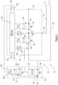
- a vehicle braking system 10 for a vehicle which includes a towing vehicle and a trailer.
- the braking system 10 includes a service line (yellow line) 14, for the supply of pressurised air to one or more service brake actuators located on the trailer and an emergency line (red line) 16 which provides the supply of pressurised air to the trailer, and is also used to operate an emergency brake on the trailer in the event of a failure in the service line 14, or associated circuitry.
- the braking system 10 includes a trailer control module 12.
- the trailer control module 12 includes a first port 18, for receiving a supply of pressurised air from a reservoir, and a second port 20 which is a delivery port for providing a pressurised air control signal via the service line 14.
- a third port 22 of the trailer control valve 12 is an exhaust port, and a fourth port 24 is provided for the pressurised air control signal from a parking brake via a parking brake supply line 25.
- the trailer control valve 12 also includes an electronic control unit (ECU) 26.
- the ECU is a microcontroller which receives and provides signals indicative of pressure in the service line 14, supply line 16, parking brake supply line 25, etc., as well as receiving and providing signals indicative of braking demand and required pressure.
- the ECU may receive and/or provide signals indicative of other characteristics of the braking system 10.
- the ECU 26 receives electrical signals via a first pressure transducer 28 which converts a measure of pressure in the service line 14 and/or emergency line 16 to a voltage.
- a second pressure transducer 30 is connected between the fourth port 24 and the ECU to provide electronic signals relating to the pressure in the parking brake supply line 25.
- the ECU 26 provides signals to a supply valve 32 and an exhaust valve which control the supply of pressurised air to the or each trailer brake actuator.
- the supply valve 32 and the exhaust valve 34 may be solenoid operated valves, with the solenoids being controlled by signals from the ECU 26.
- the supply valve 32 includes an inlet 36 which is connected to the first port 18, and hence to the emergency line 16, and an outlet 38 which is connected to the exhaust valve 34 and to the first pressure transducer 28. In a first condition, the inlet 36 is disconnected from the outlet 38. In a second condition, the inlet 36 is fluidly communicable with the outlet 38. In an embodiment, the supply valve 36 is biased to its first condition, for example by a spring 40.
- the supply valve is normally closed, until the ECU 26 provides an electrical signal, i.e. a voltage, to the solenoid to override the bias, and place the supply valve in the second, open condition, such that pressurised air can be supplied to the exhaust valve 34.
- the exhaust valve 34 also includes an inlet 42 and an outlet 44. In a first condition, the inlet 42 is fluidly communicable with the outlet 44. In a second condition, the inlet is disconnected from the outlet 44.
- the exhaust valve is biased to its first condition, for example by a spring 46. In other words, the exhaust valve 34 is normally open, unless and until the ECU 26 provides a signal, i.e. a voltage, to the solenoid of the exhaust valve 34 to override the bias, and place the exhaust valve 34 in the second, closed condition.
- supply and exhaust valves 32, 34 need not be solenoid valves and may be pneumatically controlled valves.
- the ECU 26 is communicable with a first transceiver which provides signals from a first electrical braking control circuit via a CANBUS connection 50.
- the first electrical braking control circuit may control the operation of brakes on a front axle of the vehicle, for example.
- the ECU is communicable with a second transceiver which provides signals from a second electrical braking control circuit via a further CANBUS connection 52.
- the second braking control circuit may control the operation of brakes on a rear axle of the vehicle.
- the first and second braking control circuits provide braking demand signals in response to the application of a braking demand made by the driver.
- the first and second electrical braking control circuits may be independently operable.
- the ECU 26 may be communicable with the emergency line restrictor (ELR) valve 15 via a third transceiver 54.
- the ECU 26 may be communicable with the ELR valve 15 via a CANBUS, or via a direct solenoid connection (as shown in Figure 1 ).
- the ECU is communicable with a fourth transceiver 56 which enables the transfer of data between the towing vehicle and the trailer.
- the fourth transceiver may follow the ISO11992 standard.
- the ELR valve 15 acts to throttle the flow of pressurised fluid from the reservoir into the emergency line 16 in the event of a rupture of in the service line 14 (see below) so that pressure drops in both, to activate the emergency braking mechanism in the trailer.
- the ELR valve 15 includes a throttle valve 62 which includes an input 64 which is fluidly communicable with the reservoir of pressurised fluid and an output 66 which is fluidly communicable with the emergency line 16. In a first condition, the inlet 64 is fluidly communicable with the outlet 66 such that the emergency line 16 is pressurised. In a second condition, the flow of fluid from the inlet 64 to the outlet 66 is throttled, to reduce the flow of pressurised fluid, and to reduce the pressure in the emergency line 66.
- the throttle valve 62 is biased to its first condition, preferably by a spring.
- the throttle valve 62 is controlled by a control valve 68, which includes an inlet 70, which is communicable with the reservoir via a first port.
- An outlet 72 is communicable with the throttle valve to control the condition of the throttle valve 62.
- the control valve 68 is solenoid controlled by a solenoid 69, and is electrically communicable with the ECU 26.
- a solenoid 69 In a first condition, the inlet 70 is closed, and the outlet 72 vents through an exhaust port 74.
- the inlet 70 In a second condition, the inlet 70 is fluidly communicable with the outlet 72, to move the throttle valve into its second condition and the exhaust port 74 is closed.
- the ELR valve is shown as being external to the trailer control module 12, and is controlled by a solenoid which receives a signal from the ECU 26.
- the ELR valve 15 is connected between the first port 18 and an emergency line connection between the towing vehicle and the trailer.
- the ELR valve 15 is integral with the trailer control module 12.
- the solenoid of the control valve 68 is controlled by the ECU 26.
- the embodiment of the trailer control module 12 shown in Figure 2 includes an additional pressure transducer 29, which provides the ECU 26 with signals which indicate the pressure in the emergency line 16.
- the trailer control module 12 is shown in normal operating mode.
- the third transceiver 54 has been replaced by a diagnostic connection 55 which is operable to provide information about the operating status of the ECU 26.
- the transceiver 54 is not required in this configuration of the trailer control module 12 because the ELR valve 15 is integral with the trailer control module 12. No service brake demand input is being made to the ECU 26 from the first or second braking circuit via CANBUS connection 50 or 52.
- the exhaust valve 34 is vented via the exhaust port 22, therefore the service line 14 is not pressurised.
- the ELR valve 15 is maintained in its first condition, such that the emergency line 16 is pressurised, and the supply of pressurised fluid to the emergency line 16 is un-throttled.
- the control valve 68 vents. In the condition shown in Figure 3 , the parking brake is not applied, therefore the transducer 30 provides a signal indicating that the parking brake line 25 is pressurised. If the transducer were to provide a signal indicating that the park brake is on because line 25 is vented, it would be possible to pressurise service line 14 to apply the service brake as a park brake.
- the trailer control module is shown in normal operating mode, with a braking demand being made via the first CANBUS connection 50 and/or the second CANBUS connection 52, i.e. via the first and/or second braking circuit(s).
- the transducer 29 ensures that the emergency line 16 remains pressurised.
- the transducer 28 provides an output to open the supply valve 32, so as to pressurise the service line 14, by the supply of pressurised fluid from the reservoir, through the supply valve 32.
- the or each brake actuator is operated to apply the or each brake to an associated trailer wheel.
- Opening the supply valve 32 also allows the flow of pressurised fluid between the supply valve 32 and the exhaust valve 34, which is closed to maintain pressure in the supply line 14.
- the ELR valve 15 remains in its first condition, i.e. un-throttled, so as to maintain pressure in the emergency line 16.
- the trailer control module is shown in a normal operating mode, but where there is a failure in the service line 14, for example the service line 14 may have ruptured, meaning that the requisite pressure cannot be achieved and/or maintained to apply the service brake or to prevent the service brake from disengaging.
- the trailer control module 12 is able to overcome this problem, as follows.
- the ECU 26 attempts to pressurise the service line 14 by opening the supply valve 32, as described above. Since the requisite pressure cannot be reached and/or maintained in the service line 14, the transducer 28 indicates a drop in pressure in the service line 14 to the ECU 26.
- the ELR valve solenoid 69 is activated by a signal from the ECU 26, to move the control valve 68 into its second condition, and hence move the throttle valve 62 into its second, throttled condition.
- the supply of pressurised fluid from the reservoir into the emergency line 16 is throttled, and since the supply valve 32 is open, the emergency line 16 is exhausted, which applies the emergency brake in the trailer.
- the parking brake line 25 remains pressurised, such that the parking brake is not applied.
- the trailer control module has CANBUS connection 56 (ISO 11992) via which the towing vehicle is able to communicate with the trailer, the braking demand signal from the brake pedal via the CAN connector(s) 50, 52 to the ECU 26, can be communicated to the trailer via the CANBUS connection 56.
- the service line 14 is effectively redundant, and may be vented.
- the configuration of the trailer control module is similar to that shown in Figure 3 , i.e. the exhaust valve 34 is vented via the exhaust port 22, and the service line 14 is not pressurised.
- the ELR valve 15 is maintained in its first condition, such that the emergency line 16 is pressurised, and the supply of pressurised fluid to the emergency line 16 is un-throttled.
- the control valve 68 vents.
- the parking brake is not being applied, because the transducer 30 provides a signal indicating that the parking brake supply line 25 is pressurised.
- the difference between this situation and the situation shown in Figure 3 is that when there is a braking demand from the CANBUS connection(s) 50, 52, the ECU 26 provides a signal to the trailer via CANBUS connection 56, and circumvents the need to pressurise the service line 14.
- the service line 14 is isolated from the emergency line by the supply valve 32.
- the service line 14 Whilst the service line 14 is effectively redundant in this arrangement, it can provide a back-up in the event that the towing vehicle is connected to a vehicle which does not have the capability to communicate with the CANBUS 56, or in the event that the CANBUS connection 56 is present between the towing vehicle and the trailer, but fails. In such a situation, the braking system operates as described in relation to Figure 5 , above.
- Figures 1 and 2 show solenoid valves as the supply valve 32 and the exhaust valve 34, whereas Figures 3-5 indicate fast acting valves, which may be as described in UK patent application number 1719309.5 . It will be understood that any appropriate type of valve may be used.
- a vehicle 200 having a front axle 202, which in an embodiment is a steering axle; a first rear axle 204, which in an embodiment may be driven; and a second rear axle 206.
- a foot brake modulator 300 is provided to receive an input to indicate a braking demand, for example from a brake demand source, i.e. a brake pedal.
- the foot brake modulator 300 provides an input data signal (indicated by a dashed line in Figure 7 ) indicative of the braking demand to a vehicle ECU 340.
- the ECU 340 may also be in communication with a yaw sensor 320 and/or a steer angle sensor 350.
- the yaw sensor 320 and the steer angle sensor 350 are operable to provide data signals (shown by dotted lines in Figure 7 ) to the ECU 340.
- the data signals can be used by the ECU 340 to modify braking demand signals transmitted by the ECU 340, for example.
- Each wheel end unit includes a brake torque control and diagnostic module 310, which are also in communication with the ECU 340.
- Each brake torque control and diagnostic module 310 is capable of receiving brake control information from and sending sensor information to the ECU 340.
- Each brake torque control module 310 may be powered via its connection to the ECU 340.
- Each wheel end unit includes a mechanical actuator for applying the brake associated with the wheel.
- the ECU 340 is capable of setting the brake torque at each individual wheel unit.
- One or more of the wheel end units may be in communication with a wheel speed sensor which provides data indicative of the speed of an associated wheel to the diagnostic module 310, which can then transmit the wheel speed data to the ECU 340.
- a trailer control module 330 is in communication with the ECU 340.
- the trailer control module 330 may be of any appropriate type, including any of the embodiments of a trailer control module described herein.
- the trailer control module may be supplied with power via its connection to the ECU 340, and may exchange data, e.g. sensor data with the ECU 340.
- each wheel end unit includes a fast acting brake valve 370 which is communicable with the ECU 340, and is able to control the associated brake actuator in response to a signal from the ECU 340.
- the braking system is flexible enough that other wheel end controls can be utilised without significantly altering the architecture, or significantly altering the functionality of the braking system.
- the embodiment shown in Figure 6C includes a relay-based modulator 380 with an associated ECU at each wheel end unit, in place of the corresponding fast acting valve 370.
- each wheel end unit includes an electro-mechanical brake 390 in place of the corresponding fast acting valve 370.
- the vehicle ECU 340 receives signals from the yaw sensor 320, the steer angle sensor 350 and the vehicle speed sensor 360.
- the ECU 340 provides signals to each brake torque control and diagnostics module 310, which is operable to communicate with the associated wheel end unit to set the brake torque at each wheel end by the wheel end control which is utilised, e.g. fast acting valve 370, relay based modulator with ECU 380 or electro-mechanical brake 390.
- a 'mini-modulator' may be used as an appropriate wheel end control. Such a control is disclosed in patent applications GB 2467957 , GB2497602 and/or EP2576300 .
Landscapes
- Engineering & Computer Science (AREA)
- Transportation (AREA)
- Mechanical Engineering (AREA)
- Physics & Mathematics (AREA)
- Fluid Mechanics (AREA)
- Regulating Braking Force (AREA)
- Valves And Accessory Devices For Braking Systems (AREA)
Claims (6)
- Un module de commande de remorque (12) pour un système de freinage (10), le module de commande de remorque (12) comprenant une unité de commande électronique (26), servant à recevoir un signal indicatif d'une demande de freinage en provenance d'au moins un circuit de commande de freinage électrique et à fournir des signaux à une soupape d'alimentation (32) et une soupape d'échappement (34) qui commandent l'alimentation en air sous pression d'un réservoir à un ou plusieurs actionneurs de frein de remorque par l'intermédiaire d'une ligne de service (14) et d'une ligne d'alimentation (16), caractérisé en ce que l'unité de commande électronique (26) sert à commander une soupape de réduction de ligne d'urgence (15) qui, à son tour, sert à commander l'écoulement du fluide sous pression du réservoir à une ligne d'alimentation (14, 16) en cas de chute de pression dans la ligne de service (14).
- Un module de commande de remorque (12) selon la revendication 1, dans lequel l'unité de commande électronique (26) reçoit des signaux du ou de chaque circuit de commande de freinage via une connexion CANBUS respective (50, 52).
- Un module de commande de remorque (12) selon les revendications 1 ou 2, dans lequel la soupape de réduction de ligne d'urgence (15) peut communiquer avec l'unité de commande électronique (26) via une connexion CANBUS.
- Un module de commande de remorque (12) selon les revendications 1 ou 2, dans lequel la soupape de réduction de ligne d'urgence (15) est intégrée au module de commande de remorque (12).
- Un module de commande de remorque (12) selon une quelconque des revendications 1 à 4, comprenant un ou plusieurs transducteurs de pression (28, 29, 30) servant à fournir des signaux à l'unité de commande électronique (26) qui sont indicatifs de la pression dans au moins une de la ligne de service (14) et la ligne d'alimentation (16, 25), et à commander au moins une de la soupape d'alimentation (32) et la soupape d'échappement (34) en réponse à des signaux reçus de l'unité de commande électronique (26).
- Un module de commande de remorque (12) selon la revendication 1, dans lequel l'unité de commande électronique (26) sert à commander la soupape de réduction de ligne d'urgence (15) qui, à son tour, sert à commander l'écoulement du fluide sous pression du réservoir à une ligne d'alimentation (14, 16) en cas de chute de pression dans la ligne de service (14), quand il n'y a pas de possibilité de communication avec une connexion CANBUS (56), ou en cas de panne dans la connexion CANBUS (56).
Applications Claiming Priority (3)
| Application Number | Priority Date | Filing Date | Title |
|---|---|---|---|
| GB1719344.2A GB2569282A (en) | 2017-11-21 | 2017-11-21 | Braking system |
| GB1719415.0A GB2569104B (en) | 2017-11-21 | 2017-11-22 | Braking system |
| PCT/EP2018/082128 WO2019101818A2 (fr) | 2017-11-21 | 2018-11-21 | Système de freinage |
Publications (3)
| Publication Number | Publication Date |
|---|---|
| EP3713801A2 EP3713801A2 (fr) | 2020-09-30 |
| EP3713801B1 true EP3713801B1 (fr) | 2024-10-30 |
| EP3713801B8 EP3713801B8 (fr) | 2024-12-04 |
Family
ID=60805733
Family Applications (1)
| Application Number | Title | Priority Date | Filing Date |
|---|---|---|---|
| EP18811476.3A Active EP3713801B8 (fr) | 2017-11-21 | 2018-11-21 | Système de freinage |
Country Status (5)
| Country | Link |
|---|---|
| US (1) | US11661040B2 (fr) |
| EP (1) | EP3713801B8 (fr) |
| CN (1) | CN111372827A (fr) |
| GB (2) | GB2569282A (fr) |
| WO (1) | WO2019101818A2 (fr) |
Families Citing this family (8)
| Publication number | Priority date | Publication date | Assignee | Title |
|---|---|---|---|---|
| US12522189B2 (en) * | 2019-06-07 | 2026-01-13 | Hl Mando Corporation | Control device structure of brake system |
| DE202019107179U1 (de) | 2019-12-20 | 2021-03-23 | Haldex Brake Products Aktiebolag | Nutzfahrzeug-Bremsventilaktuator und Nutzfahrzeug-Bremsventil |
| DE202020104139U1 (de) | 2020-07-17 | 2021-10-20 | Haldex Brake Products Aktiebolag | Schwenkanker-Bremsventilaktuator |
| KR102935122B1 (ko) * | 2021-03-11 | 2026-03-06 | 현대자동차주식회사 | 자동차의 제동 제어 시스템 및 방법 |
| DE202021103036U1 (de) | 2021-06-04 | 2021-07-20 | Haldex Brake Products Aktiebolag | Fahrzeugrad-Steuereinheit und Lenk- und/oder Bremssystem eines Fahrzeugs |
| CN115028101B (zh) * | 2022-06-21 | 2025-12-09 | 徐州重型机械有限公司 | 起重机的制动控制系统和起重机 |
| US12605976B2 (en) | 2022-12-08 | 2026-04-21 | Bendix Commercial Vehicle Systems Llc | System and method for failsafe operation of a tractor protection control module |
| KR20250014952A (ko) | 2023-07-24 | 2025-02-03 | 현대자동차주식회사 | EMB(electro mechanical brake) 비상제동 장치 및 비상제동 방법 |
Family Cites Families (27)
| Publication number | Priority date | Publication date | Assignee | Title |
|---|---|---|---|---|
| US3761139A (en) * | 1972-03-27 | 1973-09-25 | Allis Chalmers | Vehicle braking system with spring applied parking brake |
| US4076325A (en) * | 1976-03-17 | 1978-02-28 | Proven Environmental Products, Inc. | Pneumatic braking system for tractor-trailer combinations |
| IT1149523B (it) * | 1982-02-01 | 1986-12-03 | Magneti Marelli Spa | Impianto pneumatico di frenatura di rimorchi |
| DE3521446A1 (de) * | 1985-06-14 | 1986-12-18 | Knorr-Bremse AG, 8000 München | Schaltungsanordnung zur erkennung eines leitungsbruches bei einer elektro-pneumatischen fahrzeugbremsanlage mit vom zugfahrzeug gesteuerter anhaengerbremse |
| GB2270355B (en) * | 1992-09-03 | 1995-10-04 | Grau Ltd | Braking systems |
| KR100224552B1 (ko) * | 1996-03-15 | 1999-10-15 | 하나와 요시카즈 | 자동차용 로크 방지 브레이크 제어 시스템 |
| US5707117A (en) * | 1996-07-19 | 1998-01-13 | General Motors Corporation | Active brake control diagnostic |
| JPH10109629A (ja) * | 1996-10-03 | 1998-04-28 | Unisia Jecs Corp | 自動変速装置と制動装置の総合制御装置 |
| DE19826130A1 (de) * | 1998-06-12 | 1999-12-16 | Bosch Gmbh Robert | Elektromechanisches Bremssystem für ein Kraftfahrzeug |
| JP2000168525A (ja) * | 1998-12-04 | 2000-06-20 | Toyota Motor Corp | 車両旋回特性制御装置 |
| DE19955798A1 (de) * | 1999-11-19 | 2001-05-23 | Wabco Gmbh & Co Ohg | Einrichtung zur Anhängerkennung |
| KR20020047550A (ko) * | 2000-12-13 | 2002-06-22 | 이계안 | 앤티록브레이크시스템의 제동안정성 개선장치 |
| US6623089B2 (en) * | 2001-08-29 | 2003-09-23 | Delphi Technologies, Inc. | Enhanced yaw rate estimation and diagnosis for vehicular applications |
| DE102005058799A1 (de) * | 2005-12-09 | 2007-06-14 | Wabco Gmbh | Elektropneumatische Bremssteuerungseinrichtung |
| GB2450468B (en) * | 2007-03-22 | 2011-06-01 | Knorr Bremse Systeme F R Nutzfahrzeuge Gmbh | Trailer electronic braking system |
| GB0705789D0 (en) * | 2007-03-26 | 2007-05-02 | Haldex Brake Products Ltd | Vehicle braking system |
| DE102007047691A1 (de) * | 2007-10-05 | 2009-04-09 | Wabco Gmbh | Elektropneumatischer Feststellbremsmodulator zur Steuerung einer Feststellbremsfunktion von Bremsen eines Anhängefahrzeugs in einem Fahrzeugzug |
| US8249789B2 (en) * | 2008-10-29 | 2012-08-21 | Bedix Commercial Vehicle Systems LLC | Spring brake valve |
| DE102009008351A1 (de) * | 2009-02-11 | 2010-08-19 | Knorr-Bremse Systeme für Nutzfahrzeuge GmbH | Druckluftversorgungssystem für Lastkraftwagenanhänger und Druckluftversorgungsverfahren |
| GB2499460B (en) * | 2012-02-20 | 2019-04-03 | Knorr Bremse Systeme Fuer Nutzfahrzeuge Gmbh | Trailer access point |
| DE102012101501B4 (de) * | 2012-02-24 | 2016-05-04 | Haldex Brake Products Gmbh | Landwirtschaftliches Zugfahrzeug |
| GB2500221A (en) * | 2012-03-14 | 2013-09-18 | Tractair Ltd | Vehicle brake apparatus having a trailer with an electro-pneumatic valve, controlled based on a vehicle parameter signal |
| ITMO20120320A1 (it) * | 2012-12-21 | 2014-06-21 | Cnh Italia Spa | Metodo ed apparato per controllare la frenatura di una combinazione trattore rimorchio. |
| GB2525642B (en) | 2014-05-01 | 2017-11-22 | Jaguar Land Rover Ltd | Automatically controlling vehicle speed in accordance with a set-speed |
| DE102014107399B4 (de) * | 2014-05-26 | 2020-03-26 | Knorr-Bremse Systeme für Nutzfahrzeuge GmbH | Elektronisch geregeltes, elektro-pneumatisches Bremssystem |
| GB2536949B (en) * | 2015-04-02 | 2021-05-12 | Knorr Bremse Systeme Fuer Nutzfahrzeuge Gmbh | Trailer brake system |
| EP3190014B1 (fr) * | 2016-01-08 | 2018-03-14 | Haldex Brake Products Aktiebolag | Installation de freinage pour un tracteur |
-
2017
- 2017-11-21 GB GB1719344.2A patent/GB2569282A/en not_active Withdrawn
- 2017-11-22 GB GB1719415.0A patent/GB2569104B/en active Active
-
2018
- 2018-11-21 WO PCT/EP2018/082128 patent/WO2019101818A2/fr not_active Ceased
- 2018-11-21 US US16/764,063 patent/US11661040B2/en active Active
- 2018-11-21 EP EP18811476.3A patent/EP3713801B8/fr active Active
- 2018-11-21 CN CN201880075238.7A patent/CN111372827A/zh active Pending
Also Published As
| Publication number | Publication date |
|---|---|
| US11661040B2 (en) | 2023-05-30 |
| US20200384963A1 (en) | 2020-12-10 |
| GB2569282A (en) | 2019-06-19 |
| GB201719415D0 (en) | 2018-01-03 |
| CN111372827A (zh) | 2020-07-03 |
| WO2019101818A2 (fr) | 2019-05-31 |
| GB201719344D0 (en) | 2018-01-03 |
| GB2569104B (en) | 2023-02-08 |
| WO2019101818A3 (fr) | 2019-07-18 |
| EP3713801A2 (fr) | 2020-09-30 |
| GB2569104A (en) | 2019-06-12 |
| EP3713801B8 (fr) | 2024-12-04 |
Similar Documents
| Publication | Publication Date | Title |
|---|---|---|
| EP3713801B1 (fr) | Système de freinage | |
| CN114650938B (zh) | 电子气动控制模块 | |
| US7784879B2 (en) | Electronic control air management with parking brake and trailer supply control | |
| US10137877B2 (en) | Brake system for motor vehicles | |
| US9205821B2 (en) | Brake system for motor vehicles | |
| CN113039102B (zh) | 用作车桥调制器和挂车控制模块的中继阀模块 | |
| EP3626557B1 (fr) | Système de frein pour un véhicule | |
| US8702179B2 (en) | Vehicle brake system | |
| CN114761294B (zh) | 单稳态和容错设计的驻车制动阀组件 | |
| JP2019514770A (ja) | 商用車の電子制御可能なエアブレーキシステム及びエアブレーキシステムを電子制御するための方法 | |
| CN117677549A (zh) | 具有旁通阀的运行安全的停车制动阀单元 | |
| CN101312864A (zh) | 电气动制动控制装置 | |
| CN110785330A (zh) | 车辆制动系统 | |
| CN112533805B (zh) | 具有关断阀的电气动的停驻制动设施以及用于对受电子控制的气动制动系统进行控制的方法 | |
| EP3626560B1 (fr) | Système de freinage pour véhicule et véhicule | |
| US11679748B2 (en) | Electronically controlled pneumatic brake system comprising an electronically controlled trailer control module | |
| CN114761295B (zh) | 用于驻车制动功能部的防失效阀单元以及驻车制动阀设施 | |
| CN112739590B (zh) | 用于自动驾驶车辆的冗余制动系统 | |
| WO2019123224A1 (fr) | Système de freinage par câble pour véhicules | |
| US20250206282A1 (en) | Service brake ventilation unit for an operationally reliable parking brake assembly | |
| EP3626558B1 (fr) | Système de frein pour véhicule | |
| US20240182012A1 (en) | Electronically slip-controllable power brake system | |
| EP4228941B1 (fr) | Modulateur de pression de freinage et utilisation d'un modulateur de pression de freinage | |
| USH1912H (en) | Remotely controlled brake system | |
| WO2025040428A1 (fr) | Modulateur de pression de frein électropneumatique |
Legal Events
| Date | Code | Title | Description |
|---|---|---|---|
| STAA | Information on the status of an ep patent application or granted ep patent |
Free format text: STATUS: UNKNOWN |
|
| STAA | Information on the status of an ep patent application or granted ep patent |
Free format text: STATUS: THE INTERNATIONAL PUBLICATION HAS BEEN MADE |
|
| PUAI | Public reference made under article 153(3) epc to a published international application that has entered the european phase |
Free format text: ORIGINAL CODE: 0009012 |
|
| STAA | Information on the status of an ep patent application or granted ep patent |
Free format text: STATUS: REQUEST FOR EXAMINATION WAS MADE |
|
| 17P | Request for examination filed |
Effective date: 20200520 |
|
| AK | Designated contracting states |
Kind code of ref document: A2 Designated state(s): AL AT BE BG CH CY CZ DE DK EE ES FI FR GB GR HR HU IE IS IT LI LT LU LV MC MK MT NL NO PL PT RO RS SE SI SK SM TR |
|
| AX | Request for extension of the european patent |
Extension state: BA ME |
|
| DAV | Request for validation of the european patent (deleted) | ||
| DAX | Request for extension of the european patent (deleted) | ||
| STAA | Information on the status of an ep patent application or granted ep patent |
Free format text: STATUS: EXAMINATION IS IN PROGRESS |
|
| 17Q | First examination report despatched |
Effective date: 20221125 |
|
| GRAP | Despatch of communication of intention to grant a patent |
Free format text: ORIGINAL CODE: EPIDOSNIGR1 |
|
| STAA | Information on the status of an ep patent application or granted ep patent |
Free format text: STATUS: GRANT OF PATENT IS INTENDED |
|
| INTG | Intention to grant announced |
Effective date: 20240528 |
|
| P01 | Opt-out of the competence of the unified patent court (upc) registered |
Free format text: CASE NUMBER: APP_39112/2024 Effective date: 20240701 |
|
| GRAS | Grant fee paid |
Free format text: ORIGINAL CODE: EPIDOSNIGR3 |
|
| GRAA | (expected) grant |
Free format text: ORIGINAL CODE: 0009210 |
|
| STAA | Information on the status of an ep patent application or granted ep patent |
Free format text: STATUS: THE PATENT HAS BEEN GRANTED |
|
| REG | Reference to a national code |
Ref country code: DE Ref legal event code: R081 Ref document number: 602018076053 Country of ref document: DE Owner name: HALDEX AKTIEBOLAG, SE Free format text: FORMER OWNER: HALDEX BRAKE PRODUCTS AB, LANDSKRONA, SE |
|
| AK | Designated contracting states |
Kind code of ref document: B1 Designated state(s): AL AT BE BG CH CY CZ DE DK EE ES FI FR GB GR HR HU IE IS IT LI LT LU LV MC MK MT NL NO PL PT RO RS SE SI SK SM TR |
|
| REG | Reference to a national code |
Ref country code: GB Ref legal event code: FG4D |
|
| REG | Reference to a national code |
Ref country code: CH Ref legal event code: EP |
|
| RAP2 | Party data changed (patent owner data changed or rights of a patent transferred) |
Owner name: HALDEX AKTIEBOLAG |
|
| REG | Reference to a national code |
Ref country code: DE Ref legal event code: R096 Ref document number: 602018076053 Country of ref document: DE |
|
| REG | Reference to a national code |
Ref country code: CH Ref legal event code: PK Free format text: BERICHTIGUNG B8 |
|
| REG | Reference to a national code |
Ref country code: IE Ref legal event code: FG4D |
|
| REG | Reference to a national code |
Ref country code: LT Ref legal event code: MG9D |
|
| REG | Reference to a national code |
Ref country code: NL Ref legal event code: MP Effective date: 20241030 |
|
| PG25 | Lapsed in a contracting state [announced via postgrant information from national office to epo] |
Ref country code: HR Free format text: LAPSE BECAUSE OF FAILURE TO SUBMIT A TRANSLATION OF THE DESCRIPTION OR TO PAY THE FEE WITHIN THE PRESCRIBED TIME-LIMIT Effective date: 20241030 Ref country code: PT Free format text: LAPSE BECAUSE OF FAILURE TO SUBMIT A TRANSLATION OF THE DESCRIPTION OR TO PAY THE FEE WITHIN THE PRESCRIBED TIME-LIMIT Effective date: 20250228 Ref country code: IS Free format text: LAPSE BECAUSE OF FAILURE TO SUBMIT A TRANSLATION OF THE DESCRIPTION OR TO PAY THE FEE WITHIN THE PRESCRIBED TIME-LIMIT Effective date: 20250228 |
|
| PG25 | Lapsed in a contracting state [announced via postgrant information from national office to epo] |
Ref country code: NL Free format text: LAPSE BECAUSE OF FAILURE TO SUBMIT A TRANSLATION OF THE DESCRIPTION OR TO PAY THE FEE WITHIN THE PRESCRIBED TIME-LIMIT Effective date: 20241030 Ref country code: FI Free format text: LAPSE BECAUSE OF FAILURE TO SUBMIT A TRANSLATION OF THE DESCRIPTION OR TO PAY THE FEE WITHIN THE PRESCRIBED TIME-LIMIT Effective date: 20241030 |
|
| REG | Reference to a national code |
Ref country code: AT Ref legal event code: MK05 Ref document number: 1736618 Country of ref document: AT Kind code of ref document: T Effective date: 20241030 |
|
| PG25 | Lapsed in a contracting state [announced via postgrant information from national office to epo] |
Ref country code: BG Free format text: LAPSE BECAUSE OF FAILURE TO SUBMIT A TRANSLATION OF THE DESCRIPTION OR TO PAY THE FEE WITHIN THE PRESCRIBED TIME-LIMIT Effective date: 20241030 |
|
| PG25 | Lapsed in a contracting state [announced via postgrant information from national office to epo] |
Ref country code: ES Free format text: LAPSE BECAUSE OF FAILURE TO SUBMIT A TRANSLATION OF THE DESCRIPTION OR TO PAY THE FEE WITHIN THE PRESCRIBED TIME-LIMIT Effective date: 20241030 |
|
| PG25 | Lapsed in a contracting state [announced via postgrant information from national office to epo] |
Ref country code: NO Free format text: LAPSE BECAUSE OF FAILURE TO SUBMIT A TRANSLATION OF THE DESCRIPTION OR TO PAY THE FEE WITHIN THE PRESCRIBED TIME-LIMIT Effective date: 20250130 |
|
| PG25 | Lapsed in a contracting state [announced via postgrant information from national office to epo] |
Ref country code: LV Free format text: LAPSE BECAUSE OF FAILURE TO SUBMIT A TRANSLATION OF THE DESCRIPTION OR TO PAY THE FEE WITHIN THE PRESCRIBED TIME-LIMIT Effective date: 20241030 Ref country code: AT Free format text: LAPSE BECAUSE OF FAILURE TO SUBMIT A TRANSLATION OF THE DESCRIPTION OR TO PAY THE FEE WITHIN THE PRESCRIBED TIME-LIMIT Effective date: 20241030 Ref country code: GR Free format text: LAPSE BECAUSE OF FAILURE TO SUBMIT A TRANSLATION OF THE DESCRIPTION OR TO PAY THE FEE WITHIN THE PRESCRIBED TIME-LIMIT Effective date: 20250131 |
|
| PG25 | Lapsed in a contracting state [announced via postgrant information from national office to epo] |
Ref country code: PL Free format text: LAPSE BECAUSE OF FAILURE TO SUBMIT A TRANSLATION OF THE DESCRIPTION OR TO PAY THE FEE WITHIN THE PRESCRIBED TIME-LIMIT Effective date: 20241030 |
|
| PG25 | Lapsed in a contracting state [announced via postgrant information from national office to epo] |
Ref country code: RS Free format text: LAPSE BECAUSE OF FAILURE TO SUBMIT A TRANSLATION OF THE DESCRIPTION OR TO PAY THE FEE WITHIN THE PRESCRIBED TIME-LIMIT Effective date: 20250130 |
|
| REG | Reference to a national code |
Ref country code: CH Ref legal event code: PL |
|
| PG25 | Lapsed in a contracting state [announced via postgrant information from national office to epo] |
Ref country code: SM Free format text: LAPSE BECAUSE OF FAILURE TO SUBMIT A TRANSLATION OF THE DESCRIPTION OR TO PAY THE FEE WITHIN THE PRESCRIBED TIME-LIMIT Effective date: 20241030 |
|
| PG25 | Lapsed in a contracting state [announced via postgrant information from national office to epo] |
Ref country code: MC Free format text: LAPSE BECAUSE OF FAILURE TO SUBMIT A TRANSLATION OF THE DESCRIPTION OR TO PAY THE FEE WITHIN THE PRESCRIBED TIME-LIMIT Effective date: 20241030 |
|
| PG25 | Lapsed in a contracting state [announced via postgrant information from national office to epo] |
Ref country code: DK Free format text: LAPSE BECAUSE OF FAILURE TO SUBMIT A TRANSLATION OF THE DESCRIPTION OR TO PAY THE FEE WITHIN THE PRESCRIBED TIME-LIMIT Effective date: 20241030 |
|
| PG25 | Lapsed in a contracting state [announced via postgrant information from national office to epo] |
Ref country code: LU Free format text: LAPSE BECAUSE OF NON-PAYMENT OF DUE FEES Effective date: 20241121 |
|
| REG | Reference to a national code |
Ref country code: CH Ref legal event code: PL |
|
| PG25 | Lapsed in a contracting state [announced via postgrant information from national office to epo] |
Ref country code: CH Free format text: LAPSE BECAUSE OF NON-PAYMENT OF DUE FEES Effective date: 20241130 |
|
| PG25 | Lapsed in a contracting state [announced via postgrant information from national office to epo] |
Ref country code: RO Free format text: LAPSE BECAUSE OF FAILURE TO SUBMIT A TRANSLATION OF THE DESCRIPTION OR TO PAY THE FEE WITHIN THE PRESCRIBED TIME-LIMIT Effective date: 20241030 |
|
| PG25 | Lapsed in a contracting state [announced via postgrant information from national office to epo] |
Ref country code: SK Free format text: LAPSE BECAUSE OF FAILURE TO SUBMIT A TRANSLATION OF THE DESCRIPTION OR TO PAY THE FEE WITHIN THE PRESCRIBED TIME-LIMIT Effective date: 20241030 |
|
| PG25 | Lapsed in a contracting state [announced via postgrant information from national office to epo] |
Ref country code: CZ Free format text: LAPSE BECAUSE OF FAILURE TO SUBMIT A TRANSLATION OF THE DESCRIPTION OR TO PAY THE FEE WITHIN THE PRESCRIBED TIME-LIMIT Effective date: 20241030 |
|
| PG25 | Lapsed in a contracting state [announced via postgrant information from national office to epo] |
Ref country code: IT Free format text: LAPSE BECAUSE OF FAILURE TO SUBMIT A TRANSLATION OF THE DESCRIPTION OR TO PAY THE FEE WITHIN THE PRESCRIBED TIME-LIMIT Effective date: 20241030 |
|
| REG | Reference to a national code |
Ref country code: DE Ref legal event code: R097 Ref document number: 602018076053 Country of ref document: DE |
|
| REG | Reference to a national code |
Ref country code: BE Ref legal event code: MM Effective date: 20241130 |
|
| PLBE | No opposition filed within time limit |
Free format text: ORIGINAL CODE: 0009261 |
|
| STAA | Information on the status of an ep patent application or granted ep patent |
Free format text: STATUS: NO OPPOSITION FILED WITHIN TIME LIMIT |
|
| PG25 | Lapsed in a contracting state [announced via postgrant information from national office to epo] |
Ref country code: SE Free format text: LAPSE BECAUSE OF FAILURE TO SUBMIT A TRANSLATION OF THE DESCRIPTION OR TO PAY THE FEE WITHIN THE PRESCRIBED TIME-LIMIT Effective date: 20241030 |
|
| 26N | No opposition filed |
Effective date: 20250731 |
|
| PG25 | Lapsed in a contracting state [announced via postgrant information from national office to epo] |
Ref country code: BE Free format text: LAPSE BECAUSE OF NON-PAYMENT OF DUE FEES Effective date: 20241130 |
|
| PG25 | Lapsed in a contracting state [announced via postgrant information from national office to epo] |
Ref country code: IE Free format text: LAPSE BECAUSE OF NON-PAYMENT OF DUE FEES Effective date: 20241121 |
|
| PGFP | Annual fee paid to national office [announced via postgrant information from national office to epo] |
Ref country code: DE Payment date: 20251106 Year of fee payment: 8 |
|
| PGFP | Annual fee paid to national office [announced via postgrant information from national office to epo] |
Ref country code: GB Payment date: 20251120 Year of fee payment: 8 |
|
| PGFP | Annual fee paid to national office [announced via postgrant information from national office to epo] |
Ref country code: FR Payment date: 20251120 Year of fee payment: 8 |
|
| PG25 | Lapsed in a contracting state [announced via postgrant information from national office to epo] |
Ref country code: HU Free format text: LAPSE BECAUSE OF FAILURE TO SUBMIT A TRANSLATION OF THE DESCRIPTION OR TO PAY THE FEE WITHIN THE PRESCRIBED TIME-LIMIT; INVALID AB INITIO Effective date: 20181121 |
|
| PG25 | Lapsed in a contracting state [announced via postgrant information from national office to epo] |
Ref country code: CY Free format text: LAPSE BECAUSE OF FAILURE TO SUBMIT A TRANSLATION OF THE DESCRIPTION OR TO PAY THE FEE WITHIN THE PRESCRIBED TIME-LIMIT; INVALID AB INITIO Effective date: 20181121 |