EP3714130B1 - Procédé et appareil de nettoyage d'un espace annulaire - Google Patents
Procédé et appareil de nettoyage d'un espace annulaire Download PDFInfo
- Publication number
- EP3714130B1 EP3714130B1 EP18808092.3A EP18808092A EP3714130B1 EP 3714130 B1 EP3714130 B1 EP 3714130B1 EP 18808092 A EP18808092 A EP 18808092A EP 3714130 B1 EP3714130 B1 EP 3714130B1
- Authority
- EP
- European Patent Office
- Prior art keywords
- casing
- fluid
- tool
- annulus
- pressure
- Prior art date
- Legal status (The legal status is an assumption and is not a legal conclusion. Google has not performed a legal analysis and makes no representation as to the accuracy of the status listed.)
- Active
Links
Images




Classifications
-
- E—FIXED CONSTRUCTIONS
- E21—EARTH OR ROCK DRILLING; MINING
- E21B—EARTH OR ROCK DRILLING; OBTAINING OIL, GAS, WATER, SOLUBLE OR MELTABLE MATERIALS OR A SLURRY OF MINERALS FROM WELLS
- E21B37/00—Methods or apparatus for cleaning boreholes or wells
-
- E—FIXED CONSTRUCTIONS
- E21—EARTH OR ROCK DRILLING; MINING
- E21B—EARTH OR ROCK DRILLING; OBTAINING OIL, GAS, WATER, SOLUBLE OR MELTABLE MATERIALS OR A SLURRY OF MINERALS FROM WELLS
- E21B17/00—Drilling rods or pipes; Flexible drill strings; Kellies; Drill collars; Sucker rods; Cables; Casings; Tubings
- E21B17/22—Rods or pipes with helical structure
-
- E—FIXED CONSTRUCTIONS
- E21—EARTH OR ROCK DRILLING; MINING
- E21B—EARTH OR ROCK DRILLING; OBTAINING OIL, GAS, WATER, SOLUBLE OR MELTABLE MATERIALS OR A SLURRY OF MINERALS FROM WELLS
- E21B21/00—Methods or apparatus for flushing boreholes, e.g. by use of exhaust air from motor
-
- E—FIXED CONSTRUCTIONS
- E21—EARTH OR ROCK DRILLING; MINING
- E21B—EARTH OR ROCK DRILLING; OBTAINING OIL, GAS, WATER, SOLUBLE OR MELTABLE MATERIALS OR A SLURRY OF MINERALS FROM WELLS
- E21B23/00—Apparatus for displacing, setting, locking, releasing or removing tools, packers or the like in boreholes or wells
- E21B23/004—Indexing systems for guiding relative movement between telescoping parts of downhole tools
-
- E—FIXED CONSTRUCTIONS
- E21—EARTH OR ROCK DRILLING; MINING
- E21B—EARTH OR ROCK DRILLING; OBTAINING OIL, GAS, WATER, SOLUBLE OR MELTABLE MATERIALS OR A SLURRY OF MINERALS FROM WELLS
- E21B29/00—Cutting or destroying pipes, packers, plugs or wire lines, located in boreholes or wells, e.g. cutting of damaged pipes, of windows; Deforming of pipes in boreholes or wells; Reconditioning of well casings while in the ground
- E21B29/10—Reconditioning of well casings, e.g. straightening
-
- E—FIXED CONSTRUCTIONS
- E21—EARTH OR ROCK DRILLING; MINING
- E21B—EARTH OR ROCK DRILLING; OBTAINING OIL, GAS, WATER, SOLUBLE OR MELTABLE MATERIALS OR A SLURRY OF MINERALS FROM WELLS
- E21B33/00—Sealing or packing boreholes or wells
- E21B33/10—Sealing or packing boreholes or wells in the borehole
- E21B33/12—Packers; Plugs
-
- E—FIXED CONSTRUCTIONS
- E21—EARTH OR ROCK DRILLING; MINING
- E21B—EARTH OR ROCK DRILLING; OBTAINING OIL, GAS, WATER, SOLUBLE OR MELTABLE MATERIALS OR A SLURRY OF MINERALS FROM WELLS
- E21B33/00—Sealing or packing boreholes or wells
- E21B33/10—Sealing or packing boreholes or wells in the borehole
- E21B33/12—Packers; Plugs
- E21B33/126—Packers; Plugs with fluid-pressure-operated elastic cup or skirt
-
- E—FIXED CONSTRUCTIONS
- E21—EARTH OR ROCK DRILLING; MINING
- E21B—EARTH OR ROCK DRILLING; OBTAINING OIL, GAS, WATER, SOLUBLE OR MELTABLE MATERIALS OR A SLURRY OF MINERALS FROM WELLS
- E21B33/00—Sealing or packing boreholes or wells
- E21B33/10—Sealing or packing boreholes or wells in the borehole
- E21B33/13—Methods or devices for cementing, for plugging holes, crevices or the like
-
- E—FIXED CONSTRUCTIONS
- E21—EARTH OR ROCK DRILLING; MINING
- E21B—EARTH OR ROCK DRILLING; OBTAINING OIL, GAS, WATER, SOLUBLE OR MELTABLE MATERIALS OR A SLURRY OF MINERALS FROM WELLS
- E21B33/00—Sealing or packing boreholes or wells
- E21B33/10—Sealing or packing boreholes or wells in the borehole
- E21B33/13—Methods or devices for cementing, for plugging holes, crevices or the like
- E21B33/14—Methods or devices for cementing, for plugging holes, crevices or the like for cementing casings into boreholes
-
- E—FIXED CONSTRUCTIONS
- E21—EARTH OR ROCK DRILLING; MINING
- E21B—EARTH OR ROCK DRILLING; OBTAINING OIL, GAS, WATER, SOLUBLE OR MELTABLE MATERIALS OR A SLURRY OF MINERALS FROM WELLS
- E21B34/00—Valve arrangements for boreholes or wells
- E21B34/06—Valve arrangements for boreholes or wells in wells
- E21B34/14—Valve arrangements for boreholes or wells in wells operated by movement of tools, e.g. sleeve valves operated by pistons or wire line tools
- E21B34/142—Valve arrangements for boreholes or wells in wells operated by movement of tools, e.g. sleeve valves operated by pistons or wire line tools unsupported or free-falling elements, e.g. balls, plugs, darts or pistons
-
- E—FIXED CONSTRUCTIONS
- E21—EARTH OR ROCK DRILLING; MINING
- E21B—EARTH OR ROCK DRILLING; OBTAINING OIL, GAS, WATER, SOLUBLE OR MELTABLE MATERIALS OR A SLURRY OF MINERALS FROM WELLS
- E21B37/00—Methods or apparatus for cleaning boreholes or wells
- E21B37/08—Methods or apparatus for cleaning boreholes or wells cleaning in situ of down-hole filters, screens, e.g. casing perforations, or gravel packs
-
- E—FIXED CONSTRUCTIONS
- E21—EARTH OR ROCK DRILLING; MINING
- E21B—EARTH OR ROCK DRILLING; OBTAINING OIL, GAS, WATER, SOLUBLE OR MELTABLE MATERIALS OR A SLURRY OF MINERALS FROM WELLS
- E21B43/00—Methods or apparatus for obtaining oil, gas, water, soluble or meltable materials or a slurry of minerals from wells
- E21B43/02—Subsoil filtering
- E21B43/04—Gravelling of wells
-
- E—FIXED CONSTRUCTIONS
- E21—EARTH OR ROCK DRILLING; MINING
- E21B—EARTH OR ROCK DRILLING; OBTAINING OIL, GAS, WATER, SOLUBLE OR MELTABLE MATERIALS OR A SLURRY OF MINERALS FROM WELLS
- E21B43/00—Methods or apparatus for obtaining oil, gas, water, soluble or meltable materials or a slurry of minerals from wells
- E21B43/11—Perforators; Permeators
- E21B43/116—Gun or shaped-charge perforators
-
- E—FIXED CONSTRUCTIONS
- E21—EARTH OR ROCK DRILLING; MINING
- E21B—EARTH OR ROCK DRILLING; OBTAINING OIL, GAS, WATER, SOLUBLE OR MELTABLE MATERIALS OR A SLURRY OF MINERALS FROM WELLS
- E21B2200/00—Special features related to earth drilling for obtaining oil, gas or water
- E21B2200/06—Sleeve valves
Definitions
- the present disclosure relates to a method and apparatus for washing an annulus. Some examples may involve washing an annulus as part of well abandonment.
- casing strings normally run concentrically within one another or suspended inside the next largest casing above as a liner.
- Each casing or liner generally extends deeper in measured depth (MD) than the previous larger size casing or liner.
- MD measured depth
- casing is run into the well starting with the casing "shoe” and ending with the casing hanger. Once at the planned depth the casing is cemented in place around the casing shoe. The cement supports and isolates the formation and casing from the main wellbore.
- drilling continues with progressively smaller drill bits through the cemented casing shoe until pressure and formation integrity require the next casing string be run and cemented. This process continues until passing through the producing or receiving formation.
- production tubing can be run from surface to the zone of interest and the tubing and production casing perforated to allow the flow of fluid out of the well in the case of a producer or into the formation in the case of an injection well.
- the annuli between the casings is normally a combination of hard cement around the shoe, contaminated softer cement on top, with the original drilling fluid on top of that.
- weighting solids in the mud such as barite
- the weighting solids in the mud such as barite
- the casing can be removed by mechanical cutting and pulling with a spear, provided the casing is free.
- a stuck casing can be "pilot milled” from the top down after pulling out the free section of casing.
- the casing can also be "section milled” by running a hydro/mechanical tool to the target depth, opening the arms on the tool then applying weight and milling away a window or section in which to place the remedial cement barrier. This can be in "open hole” with the formation or inside the next largest casing.
- This technique involves running a tool into a casing to perform the perf and wash operation into the well.
- This can, of itself, provide problems if, for example, the tool encounters a surge of pressure within the casing.
- a surge in pressure may urge the tool, and any tubing or equipment attached thereto, back through the casing towards the surface of the well. In turn this may, for example, cause tubing to spool out of the casing at the surface, which may cause a danger to personnel working at surface.
- WO 2015/026239 A2 teaches a method of performing a plug and abandonment operation in a well by the use of a combined perforate and wash tool, the tool comprising a perforation tool at a lower end, at least one lower sealing arrangement arranged below a fluid displacement arrangement comprising a plurality of radial holes, and at least one sealing arrangement arranged above the plurality of radial holes.
- the method comprises the steps of: a) lowering the tool to the desired location in the well, b) perforating at least a section of the well, if the section is not already perforated, c) washing said perforated section by pumping washing and/or cleaning fluid through the radial holes in the displacement arrangement, d) sealing off a lower portion of the well at a location below the perforated section by the use of the lower sealing arrangement, e) sealing off the well in a lower portion of the perforated section by using the upper sealing arrangement, f) pumping sealing fluid through the plurality of radial holes in the displacement arrangement; and, g) lifting the tool through, and above, the perforated section, while continuing pumping of the sealing fluid.
- WO 2012/105852 A1 teaches a tool for the handling of wells through a formation, and which is taken out of operation with a device for a closing plug of a material that can be hardened, such as concrete, where there is a casing pipe in the well that is cemented against the wall in the bore hole with concrete.
- the tool is characterised in that it comprises an assembled unit from the following three sections; a perforating lance comprising a number of explosive charges to form by detonation a row of holes in the pipe and out into the surrounding layer of concrete, a cleaning unit for mechanical cleaning of the inner wall of the pipe in the perforated area and a flushing unit to loosen, dissolve and flush away the hardened cement material between the outer wall of the pipe and the wall of the bore hole.
- WO 2015/034369 A1 teaches a method for isolation of a permeable zone in a subterranean well, wherein the well is provided with a pipe body, wherein the method comprises the following steps: (A) lowering a perforation tool into the pipe body; (B) forming holes in the pipe body along a longitudinal section; (C) pumping a flushing fluid out through outlets in a flushing tool, into the pipe body and further out into an annulus; (D) pumping a fluidized plugging material out through the flushing tool, into the pipe body and further out into the annulus; and, (E) placing the fluidized plugging material along the longitudinal section so as to form a plug across the cross section of the well, whereby the plug fills the pipe body and the annulus.
- WO2014/109643 A1 teaches a petroleum well drill or coiled tubing string mounted on a fishing tool.
- the tool comprises a main body comprising a lower housing with a magnet having at least one magnet surface facing downwards in said well at a lower end of said lower housing and arranged for catching and holding undesired magnetic objects present in said well.
- the main body provided with a connector to said drill - or coiled tubing string at its upper end.
- the tool further comprises a generally cylindrical upper housing with a central channel with laterally directed curl flow forming nozzles through the cylindrical wall of said upper housing, said nozzles leading out into one or more helical grooves between helical ridges, said magnet comprising permanent magnets arranged in a magnetization pattern which concentrates their combined magnetic flux through said downwards facing surface.
- An aspect of the present disclosure relates to a method for washing an annulus that at least partially surrounds a casing in a well according to appended claim 1.
- the method may be used to wash the annulus in a well to remove debris therefrom, or to remove an existing cement sheath in the annulus, by injecting washing fluid from the injection aperture of the tool and through the first casing aperture and into the annulus.
- the annulus may be between the casing and a formation, or between two sections of casing.
- the washing fluid may re-enter the casing from the annulus by passing through the second casing aperture.
- the reduced pressure in the inflow region may assist flow from the annulus and into the casing. That is, the reduced pressure may provide a "suction" effect within the casing.
- the fluid which has reentered the casing may be flowed to surface.
- Further operations may include, for example, cementing operations, monitoring operations, treatment operations, steps to abandon the well (e.g. to plug the well) or the like. Having already washed the annulus, the efficacy of further operations may be improved. For example, cementing operations may be able to be performed more easily due to a reduction in obstructive debris or oil residue in the annulus, which may allow the cement to have a better bond with the casing.
- Washing the annulus may provide a localised region of increased flow velocity in the annulus, which may be achieved by the removal of blockages such as debris from the annulus. Increased flow velocity may assist to ensure that further operations are performed more fully and/or more quickly.
- the injection aperture may inject the washing fluid into a region between the tool and the casing.
- the inflow region may be remote from the delivery of the washing fluid from the injection region.
- the inflow region may be axially spaced apart from the injection region.
- the method may comprise reducing the pressure in the inflow region by generating a localised fluid turbulence within the casing, thereby creating the inflow region within the casing having reduced pressure relative to the annulus.
- the method comprises reducing the pressure in the inflow region by providing a localised increase in a velocity of a fluid within the casing.
- the fluid in this case is defined as an operating fluid.
- the velocity of the operating fluid may be increased by, for example, swirling said fluid within the casing. Swirling the operating fluid may create a vortex of operating fluid in the inflow region.
- the method may comprise providing a localised increase in a velocity of the operating fluid delivered into the casing from the tool.
- the operating fluid may be delivered into a region which is remote from the injection aperture of the tool.
- a pressure reduction apparatus is provided on the tool to facilitate or provide a pressure reduction in the inflow region.
- the pressure reduction apparatus comprises at least one fluid aperture through which the operating fluid can be flowed (e.g. injected) into the casing.
- the pressure reduction apparatus may be configured to establish a desired flow regime within the casing to encourage or provide a reduced pressure in the inflow region, for example a turbulent flow regime.
- the pressure reduction apparatus may direct an operating fluid being flowed therefrom in a specific direction, e.g. with a component of velocity directed circumferentially and/or helically and/or vertically relative to the tool.
- the operating fluid may be the same fluid as the washing fluid. A portion of the washing fluid may be separated from a main flow of washing fluid and used as the operating fluid. Alternatively, the operating fluid may be different to the washing fluid (e.g. an entirely different fluid flow and/or entirely different fluid).
- the operating and/or washing fluid may be selected to have specific properties, e.g. a preferred density, to enable either or both of the operating and washing fluid to wash the annulus or create an increase in fluid velocity most effectively.
- the method may comprise flowing the operating fluid through the at least one fluid aperture or nozzle on the pressure reduction apparatus, the at least one fluid aperture or nozzle being configured to provide a direction to the flow therefrom.
- the at least one fluid aperture or nozzle may be shaped to provide a flow direction to the operating fluid.
- the at least one fluid aperture or nozzle may be configured to create a jet of operating fluid.
- the method may comprise flowing the operating fluid through multiple fluid apertures or nozzles located on the pressure reduction apparatus.
- the pressure reduction apparatus comprises one or more vanes.
- the vane or vanes may assist to direct the flow of operating fluid from the at least one fluid aperture or nozzle, for example to generate a swirl of operating fluid.
- At least one fluid aperture or nozzle of the pressure reduction apparatus may be posited intermediate two vanes.
- At least one fluid aperture or nozzle of the pressure reduction apparatus is located on a vane.
- the vane may have a side portion and a tip portion, and the fluid aperture or nozzle may be located on the side portion or the tip portion of the vane.
- the method may comprise flowing the operating fluid through a plurality of fluid apertures or nozzles located on the side and/or tip portions of the vane or vanes
- the method may comprise fluidly operating the pressure reduction apparatus (i.e. using a fluid to operate the pressure reduction apparatus).
- the degree of operation of the pressure reduction apparatus may be controlled by the operating fluid. For example, a reduced flow of operating fluid may correspondingly diminish the operation of the pressure reduction apparatus, for example by reducing flow through the at least one fluid aperture or nozzle of the pressure reduction apparatus.
- the method may comprise varying the configuration of the at least one fluid aperture or nozzle.
- the method may comprise configuring the at least one fluid aperture or nozzle to an open, closed and/or intermediate configuration.
- the pressure reduction apparatus may comprise a restriction component which may function to restrict flow of operating fluid through the at least one fluid aperture or nozzle of the pressure reduction apparatus, for example by occluding or partially occluding the at least one fluid aperture or nozzle.
- the restriction component may be able to be moved relative to the pressure reduction apparatus in order to restrict the flow of operating fluid through the at least one fluid aperture or nozzle.
- the restriction component may be, for example, a sleeve.
- the restriction component may be operated by, for example, a dropped ball, a dart, hydraulic action, via a wire extending from surface, or the like.
- An indexing tool may be used to control operation of the restriction component.
- the indexing tool may be used to control the movement of the restriction component to incrementally close or open the at least one fluid aperture or nozzle of the pressure reduction apparatus by occluding the at least one fluid aperture or nozzle with the restriction component.
- the indexing tool may comprise a ratchet system, for example.
- the indexing tool may be operated by dropping an object into the well, which may contact the indexing tool to move the restriction component. Additionally or alternatively, the indexing tool may be controlled by hydraulic action, wireline, or the like.
- the method may comprise perforating the casing to provide one or both of the first and second casing apertures.
- the method may comprise perforating the casing to provide a plurality of first casing apertures.
- the method may comprise perforating the casing to provide a plurality of second casing apertures.
- the method may comprise providing a perforation system to provide one or both of the first and second casing apertures.
- the perforation system may be integrated into the tool.
- the perforation system may be, for example, an array of TCP guns.
- the perforation system may be run into the well ahead of the tool, for example on a leading end of the tool.
- the perforation system may be released from the tool after use.
- the perforation system may be retrieved to the surface of the well, or may be dropped down the well.
- the method may comprise providing a perforated section of casing, having existing perforations, in the well.
- the existing perforations may provide one or both of the first and second casing apertures. As such, the method may not require perforation of the casing with the perforation system.
- the method may comprise opening existing perforations on the casing, for example an existing first and second casing aperture.
- the method may comprise providing a sealing arrangement between the tool and the casing to restrict flow of the washing fluid in the casing.
- the sealing arrangement may define an injection region within the casing.
- the sealing arrangement may function to isolate the injection region from the inflow region.
- the sealing arrangement provided between the tool and the casing may be or comprise, for example, a cup seal arrangement.
- the sealing arrangement may ensure that the flow of washing fluid from the injection region to the pressure reduction apparatus is via the annulus, i.e. the sealing arrangement may be, at least partially, provided intermediate the injection region on the tool and the inflow region such that the washing fluid may flow from the injection region to the inflow region via the annulus.
- the sealing arrangement may be operated by flow through the injection aperture. For example, flow through the injection aperture may activate the sealing arrangement.
- the method may comprise providing a plurality of seals on the tool, e.g. a plurality of cup seals.
- Two seals may be provided on the tool, e.g. two cup seals.
- Each of the plurality of seals may be axially separated relative to the tool.
- Each of the two seals may be provided on opposing axial sides of the injection aperture.
- each of the plurality of cup seals may be oppositely oriented on the tool.
- the plurality of seals may assist in flowing the washing fluid from the tool into the annulus, while preventing the washing fluid from dispersing in a region between the tool and the casing without, or with minimised, flow into the annulus.
- the method may comprise using the tool to inject a washing fluid into the annulus, which may initially collect in the injection region between the tool and the casing.
- the volume of fluid able to collect in the injection region may be limited by the presence of a seal on either side of the injection aperture, e.g. uphole and downhole of the injection aperture.
- the sealing arrangement may assist to improve the efficiency of the flow of fluid from the injection region to the annulus.
- the plurality of seals may be used to assist in establishing the positioning of the tool in the well.
- the seals may permit pressure testing in the injection region to establish positioning of the tool relative to the first and second casing apertures.
- washing fluid injected from the tool may flow into the annulus.
- the washing fluid may collect between the tool and the casing, causing an increase in pressure of the washing fluid in the injection region between the sealing arrangement.
- the method may comprise detecting an increase and/or decrease in pressure of the washing fluid.
- the tool may be equipped with a pressure sensor to assist herewith.
- the method may comprise bypassing a resident fluid in the casing around the tool, for example when positioning the tool in the casing. Bypassing a resident fluid around the tool may allow easier movement and placement of the tool inside the casing.
- the method may comprise flowing a resident fluid through a bypass arrangement located in the tool.
- a bypass arrangement may extend from a downhole region of the tool to an uphole region of the tool.
- the method may comprise providing one or more downhole bypass fluid ports and one or more uphole bypass fluid ports on the tool to allow fluid to enter and exit the bypass arrangement.
- Downhole bypass fluid ports may be provided on the tool further downhole of the injection aperture, and sealing arrangement if present, while uphole bypass fluid ports may be provided on the tool further uphole of the injection aperture, and sealing arrangement if present.
- the bypass arrangement may facilitate the flow of fluid between regions downhole and uphole of the tool, thereby bypassing components which restrict, or which may be intended to restrict, the flow of fluid in the casing such as a sealing arrangement or a plug.
- the bypass arrangement may facilitate easier placement of the tool in the casing, by mitigating against the occurrence of a high differential pressure occurring across uphole and downhole regions of the tool.
- the method may comprise flowing more than one fluid, e.g. more than one washing fluid, through the tool.
- the method may comprise flowing a first fluid through the tool.
- the first fluid may be, for example, water.
- a second fluid may be flowed through the tool.
- the second fluid may be a spacer fluid.
- the spacer fluid may be, for example water, or a water based fluid, combined with additional chemicals, for example surfactants.
- a third fluid may be flowed through the tool.
- the third fluid may be, for example, cement.
- each fluid may be separated by a separator object, such as a dart. Said separator object may restrict the mixing of each different fluid when in the tool string.
- the method may comprise dropping or delivering a flow restrictor, such as a dart, into the tool.
- a flow restrictor such as a dart
- the flow restrictor may seat in a restrictor seat.
- the flow restrictor may block, or restrict, fluid flow through the tool downhole of the flow restrictor. As such the flow restrictor may block fluid flow through a central bore of the tool.
- the pressure in the tool may increase.
- the method may comprise detecting an increase in pressure in the tool as a result of the flow restrictor seating in the restrictor seat. Such an increase in pressure may be detectable at surface.
- the flow restrictor may assist the user to know when a subsequent fluid (e.g.
- a first fluid or a second fluid or a third fluid has reached the tool, by providing a surge in pressure in the tool.
- the flow restrictor may be able to be removed from the tool by increasing the pressure in the tool. The increase in pressure may force the dart, or dropped object, to displace from the restrictor seat, becoming dislodged from the tool and passing therethrough.
- the method may comprise flowing the washing fluid from the injection aperture and into the annulus at the same time as the tool is moved relative to the casing.
- the method may comprise moving the tool through the casing from an uphole location to a downhole location (i.e. top-down), or vice versa (i.e. bottom-up), while at the same time flowing the washing fluid from the injection aperture and into the annulus.
- the washing fluid may be flowed through or filled into the entire annulus by movement of the tool through the casing.
- the apertures through which the washing fluid flows between casing and annulus may change.
- the casing may comprise a plurality of casing apertures. As the tool is moved through the casing, at least one of the plurality of casing apertures may function as a first casing aperture (i.e.
- an aperture that has functioned as a first aperture may also function as a second aperture, and vice versa.
- the washing fluid may be flowed into the annulus, moving the tool in a bottom-up configuration.
- a first casing aperture previously used to flow washing fluid from the injection region to the annulus may subsequently be used as second casing aperture to flow washing fluid from the annulus to the inflow region.
- the method may comprise flowing the washing fluid into the annulus at a rate proportionate to the velocity of movement of the tool through the casing.
- the method may comprise moving the tool through the casing in an incremental step-wise motion while flowing the washing fluid into the annulus.
- the tool may be held stationary while washing fluid is flowed into the annulus for a predetermined period of time (e.g. 5 minutes), before being moved through the casing to a different location where the tool is again held stationary while washing fluid is flowed into the annulus.
- the alternation of flowing washing fluid into the annulus and moving the tool through the casing may be repeated as many times as is deemed necessary to wash the annulus.
- Such movement of the tool through the casing may ensure that an even volume of the washing fluid is flowed into or through the casing.
- the method may comprise removing the tool from the casing. Removal of the tool from the casing may comprise rotation of a work string to which the tool is connected, while the tool remains stationary. As such, the tool may be connected to the string via a swivel arrangement. Such rotation of the string may assist to stir up solids in the casing, and thereby assist in clearing the solids from the well, as the string is rotated.
- the method may comprise operating a single use component to assist in the removal of the tool from the casing.
- the method may comprise pressurisation of the tool to rupture a burst disk, or dislodge an object e.g. a dart, on a downhole section of the tool and permit fluid flow from the tool into the casing.
- Operation of the single use component may permit the tool to be more easily removed from the well, for example by allowing fluid (e.g. cement) in the tool or associated string to flow out of the tool and remain in the well, as the tool is lifted.
- the single use component comprises a dislodged object
- the tool may be reused, and the dislodged object replaced by dropping another similar object into the tool.
- the single use component may be the flow restrictor.
- the method may comprise the setting of a plug in the well, for example extending the entire diameter of the well, both inside and outside of the casing.
- the tool may comprise a plug, which may be detached from the tool and set in the casing downhole of the tool.
- the plug may be attached to the tool via a release mechanism, such as a pressure-release mechanism.
- the method may comprise increasing the pressure of the fluid within the tool to release the plug.
- the plug may facilitate further operations using the tool, for example cementing operations, e.g. by supporting a plug of cement from below.
- the plug may be set downhole of the first and second casing apertures.
- the plug may be, for example, a cement plug.
- the plug may be made of a synthetic material, for example a plastics material, rubber, or the like.
- the method may comprise using the tool to perform cementing operations.
- the cementing operations may comprise flowing cement into the annulus between the casing and the formation, or between two casings.
- the cementing operations may comprise flowing cement into the casing.
- the cementing operations may comprise flowing cement from the tool and into the annulus via the injection region.
- the cementing operations may comprise flowing the cement from the annulus and into the inflow region uphole of the sealing arrangement.
- the method may comprise providing the tool with a cement bypass arrangement.
- the cementing operations may comprise flowing the cement through the cement bypass arrangement from a region between the tool and the casing uphole of a sealing arrangement associated with the injection aperture and into the casing downhole of the sealing arrangement.
- the cement bypass arrangement may be the same as the bypass arrangement. I.e. the cementing operations may comprise flowing cement from the annulus into a region between the tool and the casing, and through an uphole bypass fluid port of the bypass arrangement so as to pass the cement into the casing from a downhole bypass fluid port.
- the cementing operations may comprise filling a region of the casing below the tool with cement, to create a cement plug.
- the method may comprise forming the cement plug on top of a conventional plug already placed in the well.
- the cementing operations may comprise filling the entire annulus adjacent the casing apertures with cement.
- the cementing operations may comprise filling the casing adjacent the first casing aperture and the second casing aperture from an uphole region to a downhole region.
- the method may comprise flowing cement from the at least one injection aperture and into the annulus at the same time as the tool is moved relative to the casing.
- the method may comprise moving the tool through the casing from an uphole location to a downhole location (i.e. top-down), or vice versa (i.e. bottom-up), while at the same time flowing the cement from the injection aperture and into the annulus and/or casing.
- the cement may be flowed through or filled into an entire circumference of the annulus by movement of the tool through the casing.
- the apertures through which the cement flows may change.
- at least one of the plurality of casing apertures may function as a first casing aperture (i.e.
- an aperture that has functioned as a first aperture may also function as a second aperture, and vice versa.
- the cement may be flowed into the annulus, moving the tool in a top-down configuration.
- the method may comprise flowing cement into the annulus at a rate proportionate to the velocity of movement of the tool through the casing.
- the method may comprise moving the tool in a continuous motion (e.g. a single continuous motion) through the casing while flowing cement into the annulus. Such movement of the tool through the casing may ensure that an even volume of the cement is flowed into or through the casing.
- the method may comprise providing a pressure bypass arrangement on the tool to reduce the effect of a surge in well fluid pressure on the tool.
- a high pressure fluid may pass through the pressure bypass arrangement on the tool, reducing the pressure acting on the surface of the tool and thereby the magnitude of force acting on the tool as a result of the high pressure.
- a "kick" of fluid pressure (for example following the creation of a perforation in the casing and providing communication to a surrounding formation) may move in an uphole direction through the tool. This may reduce the movement of the tool as a result of the high pressure "kick", and thus reduce the safety risks of using the tool.
- the pressure bypass arrangement may form an integral part of the tool.
- the method may comprise configuring the pressure bypass arrangement to permit flow of a fluid therethrough when the tool is being run into the casing.
- the pressure bypass arrangement may comprise a port that may be opened when the tool is being run into the casing to permit fluid flow therethrough. Permitting flow through the pressure bypass arrangement when the tool is being run in the casing may permit the tool to be run into the well with reduced fluid resistance, for example because fluid is more able to bypass the pressure bypass arrangement.
- the pressure bypass arrangement may mitigate against the occurrence of a high differential pressure occurring across an uphole and a downhole section of the pressure bypass arrangement.
- the pressure bypass arrangement may comprise a central bore through which a fluid may flow.
- the pressure bypass arrangement may comprise at least one pressure bypass port to allow fluid, e.g. a high pressure fluid, to flow out of the central bore and into the casing, for example.
- the pressure bypass arrangement may comprise an actuation mechanism to selectively open and close the pressure bypass port.
- the actuation mechanism may be in the form of a sleeve.
- the actuation mechanism may be controlled or actuated by a fluid flowing in the central bore.
- the force of a fluid flowing in the central bore may act upon the actuation mechanism to bias the actuation mechanism to open the at least one pressure bypass port.
- the actuation mechanism may be normally biased towards the closed position.
- the actuation mechanism may be normally biased towards the closed position by action of a biasing member, for example a spring.
- An aspect of the present disclosure relates to a downhole apparatus for washing an annulus in a well according to appended claim 10.
- the downhole apparatus may be positioned in a well, and a washing fluid passed through the fluid injection port into an annulus to wash the annulus.
- the downhole apparatus comprises a pressure reduction apparatus to establish a pressure differential between the annulus and the downhole tool such that the washing fluid flows from the fluid injection port and towards the pressure reduction apparatus, thereby washing the annulus.
- the pressure reduction tool comprises at least one fluid aperture for passing a fluid therethrough.
- the fluid passing through the at least one fluid aperture is an operating fluid.
- the operating fluid may be the same as the washing fluid.
- the at least one fluid aperture may be configured or positioned to direct an operating fluid being flowed therefrom in a specific direction.
- the pressure reduction apparatus comprises at least one fluid aperture configured to impart a helical component of velocity to the operating fluid when passed therethrough.
- the at least one fluid aperture may comprise a nozzle, for example to augment the speed of a fluid passing therethrough, and/or to control the flow direction of a fluid passing therethrough.
- the pressure reduction tool comprises a vane or vanes extending helically relative to the axis of the tool.
- the vane or vanes may assist to control the direction of an operating fluid passing through the at least one fluid aperture in the pressure reduction tool.
- the vane or vanes may assist to induce a swirling or helical motion of a fluid.
- the at least one fluid aperture of the pressure reduction tool is located on the helically extending vane or vanes. In this way, the positioning of the at least one fluid aperture, combined with the shape of the helically extending vane or vanes may assist to provide a swirling or helical motion of a fluid passing therethrough.
- the downhole apparatus comprises a sealing arrangement.
- the sealing arrangement may comprise more than one seal.
- the downhole apparatus may comprise an upper seal (e.g. a cup seal) located uphole of the fluid injection port.
- the downhole apparatus may comprise a lower seal (e.g. a cup seal) located downhole of the fluid injection port.
- the upper seal and the lower seal are or comprise a cup seal, the upper seal and the lower seal may be oriented opposite one another.
- the downhole apparatus may comprise a bypass arrangement having an uphole bypass port positioned uphole of the sealing arrangement and a downhole bypass port positioned downhole of the sealing arrangement.
- a bypass arrangement may allow a fluid to flow through and/or past the downhole apparatus, without the flow being restricted by the sealing arrangement.
- resident fluid may provide resistance to motion as a result of the restrictions of the sealing arrangement.
- the bypass arrangement may reduce such resistance to motion of the tool.
- a user may be able to open and close the uphole and/or downhole bypass ports to provide variable operation of the bypass arrangement.
- the downhole apparatus may comprise a releasable plug arrangement.
- the releasable plug arrangement may be able to be positioned in a casing, for example.
- the releasable plug arrangement may facilitate the performance of cementing operations, for example, such as by supporting a plug of cement from below.
- the downhole apparatus may comprise a flow restrictor seating arrangement.
- the flow restrictor seating arrangement may be configured to catch a flow restrictor such as a dart, or other object, released from the surface of the well.
- the flow restrictor may enter the tool, and block or restrict fluid flow through the central bore of the external housing. While a flow restrictor is in place, fluid may flow from the tool only via the injection ports.
- a flow restrictor such as a dart, or dropped object, may be dislodged from the flow restrictor seating arrangement by the user.
- the user may dislodge the flow restrictor by increasing the fluid pressure in the tool.
- fluid flow may once again be established through the bore of the external housing.
- the bore of the external housing may extend along the entire axial length of the downhole apparatus e.g. along the entire axial length of the downhole apparatus in the configuration in which washing operations are performed.
- the downhole apparatus may comprise a pressure bypass arrangement.
- the pressure bypass arrangement may facilitate running the tool into the casing by permitting the flow of a fluid past or through the tool when the tool is run downhole.
- the pressure bypass arrangement may be located uphole of the pressure reduction tool and the seal or sealing arrangement.
- a described example relates to a method for plugging a well which includes a wellbore casing and an annulus at least partially surrounding the wellbore casing, comprising:
- the method may comprise providing a plug in the annulus.
- the method may comprise providing a plug within the casing.
- the method may comprise providing a cement plug.
- the cement plug may be provided above a support plug.
- the method may comprise setting the support plug.
- the support plug may be, for example, a plug made from synthetic plastics or rubber material.
- the support plug may support the cement plug.
- the support plug may permit the cement plug to be formed thereon.
- the cement plug may be provided by flowing cement via a cement bypass arrangement to, for example, bypass a sealing arrangement on the tool.
- the cement bypass arrangement may extend through the tool.
- the cement plug may be provided by flowing cement via the injection aperture to an uphole region of the bypass arrangement, and exiting from a downhole region of the cement bypass arrangement.
- the cement may be flowed from the injection aperture and through the first casing aperture into the annulus, and flowed from the annulus back through the second casing apertures and into the uphole region of the bypass arrangement.
- the cement bypass arrangement may permit cement to be disposed in a location downhole of the tool.
- Figure 1 is a schematic illustration of a tool 10 used for washing an annulus region in a well.
- the tool 10 is attached to a tool string 12 via disconnect 14, and the tool string 12 is itself attached to a work string (not shown).
- the work string may be, for example, jointed pipe and/or coiled tubing, and may be used to convey the tool 10 into the well, and conduct fluid, e.g. a washing fluid, between the surface and the tool 10.
- the tool 10 comprises injection apertures 16 through which a fluid can be flowed, with cup seals 18, 20 provided on either axial side of the injection apertures 16.
- the cup seals 18, 20 provide a seal between the tool and the casing 40 and define an injection region 39 therebetween.
- the tool 10 further includes a pressure reduction apparatus 34 positioned uphole of the cup seals 18, 20 and the injection apertures 16, wherein the pressure reduction apparatus 34 comprises a plurality of fluid apertures 32 and vanes 36.
- the apertures 32 may be placed, and shaped, so as to confer a substantial circumferential component of velocity to an operating fluid flowing therethrough.
- the apertures 32 may include nozzles, designed to increase the velocity to the operating fluid, and/or eject the operating fluid from the pressure reduction apparatus 34 in a helical direction.
- vanes 36 are configured to encourage flow in a radial direction of the fluid flowing from the apertures 32. As such, fluid passing from the pressure reduction apparatus 34 tends to swirl around the apparatus 34, thereby increasing the speed of fluid flow in this region and establishing a localised reduction in pressure. As will be described in more detail below, this area of reduced pressure encourages flow from an annulus region surrounding the casing 40, and as such the area adjacent the pressure reduction apparatus 34 within the casing 40 may be defined as an inflow region 23.
- the tool 10 further includes a perforation system 26 at the leading end of the tool 10 for use in establishing perforations in the casing 40.
- the perforation system 26 may comprise, for example, TCP guns, fluid jet perforating devices, chemical cutting devices, tubing punches, or the like. It should be noted that, although a perforation system 26 is shown in this example, in other examples a perforation system may not be necessary. Instead, the tool 10 may be run into a section of casing having pre-existing perforations, for example.
- the tool 10 further includes a burst disk sub 30, dart sub 22 and dart catcher 24.
- a dart (not shown) may be used to seat in the dart sub 22, thereby blocking flow through the dart sub 22.
- fluid may only pass from the tool through the injection apertures 16 or the apertures 32 of the pressure reduction apparatus 34.
- the tool 10 includes a plug 28 axially downhole of the dart sub 22 and dart catcher 24.
- the plug 28 is attached to the tool 10 via a pressure release mechanism, such that the plug 28 may be released upon pressurisation of the fluid in the tool 10.
- a pressure release mechanism such that there are several known release mechanisms that would be suitable for this purpose.
- Figure 2 shows a section of the tool 10 in greater detail, including the casing 40 in which the tool 10 has been placed, and a surrounding formation 42.
- An annulus 46 is defined between the casing 40 and formation 42, and in the present example the annulus is filled with cement 44 which is to be at least partially removed by action of the tool. In alternative examples the annulus 46 may be filled with debris, for example from the original well drilling operation.
- Perforations 38 in the casing 40 created by the perforation system 26 ( Figure 1 ), establish fluid communication between the casing 40 and annulus 46. In this respect the presence of the seals 18, 20 provide or create a communication path between the injection region 39 and the inflow region 23 via the annulus 46.
- washing fluid is pumped from surface and exits the tool 10 via the injection apertures 16 and into the injection region 39, and then into the annulus 46 via one or more of the casing perforations 38, illustrated by arrows A.
- a perforation 38 which provides such communication of fluid into the annulus 46 may be defined as a first casing aperture 38a.
- a plurality of first casing apertures 38a may accommodate flow into the annulus 46.
- a perforation 38 which provides such communication of fluid from the annulus 46 may be defined as a second casing aperture 38b.
- a plurality of second casing apertures 38b may accommodate flow from the annulus 46.
- the washing fluid and entrained cement debris may then flow to surface in the direction of arrows B.
- a portion of the washing fluid also flows from the apertures 32 of the pressure reduction apparatus 34 (indicated by arrows G) and into the inflow region 23.
- the swirling motion of the fluid caused by the pressure reduction apparatus 34 creates a localised region of relatively lower pressure, at least relative to the pressure within the annulus 46.
- This lower pressure within the inflow region 23 assists to draw or encourage the washing fluid and cement debris into the casing 40 from the annulus 46. This can assist in providing a better cleaning or washing within the annulus 46.
- the tool 10 can be moved uphole and downhole relative to the casing 40 to wash an extended length of the annulus 46.
- the inflow region 23 and injection region 39 move with the tool 10.
- a perforation 38 which at one stage functioned as a first casing aperture 38a (i.e., to allow flow into the annulus 46), may later function as second casing aperture 38b (i.e., to allow flow from the annulus 46).
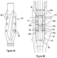
- FIGs 3A and 3B illustrate an example of the pressure reduction apparatus 34.
- the pressure reduction apparatus 34 comprises the apertures 32 and vanes 36, which as noted above encourage a swirling or turbulent flow region within the inflow region 23 ( Figures 1 and 2 ).
- Apertures 32 are located on the outer circumferential surface of the vanes 36 (i.e. the tips of the vanes), as well as in the recessed sections between the vanes 36.
- FIG. 3B illustrates a sectional view of the pressure reduction apparatus 34.
- the pressure reduction apparatus 34 comprises a flow distribution sleeve 50 which includes a plurality of radial ports 56, wherein the flow distribution sleeve 50 is mounted within the apparatus 34 to define a distribution annulus 57 which communicates with all of the apertures 32. When the radial ports 56 are opened, fluid may thus flow from the apparatus 34.
- the pressure reduction apparatus 34 further includes an internal sleeve system 52 which functions to selectively close and open the radial ports 56 in the flow distribution sleeve 50, thus to selectively permit flow from the pressure reduction apparatus 34.
- the sleeve system 52 includes an upper sleeve 52a and a lower sleeve 52b, with the upper and lower sleeves 52a, 52b initially fastened to the flow distribution sleeve 50 via respective shear pins 54a, 54b. While the present example uses shear pins, multiple alternative options are possible, and in some cases resettable options may be used.
- the lower sleeve 52b closes the radial ports 56 in the flow distribution sleeve 50.
- Each sleeve 52a, 52b includes a respective seat 53a, 53b for receiving an object, such as a ball or dart, dropped from surface.
- the seat 53b of the lower sleeve 52b defines a smaller diameter than the seat 53a of the upper sleeve 52a to facilitate sequential operation using appropriately sized objects.
- an object (not shown) is dropped to engage the seat 53b of the lower sleeve 52b.
- the impact force, and/or pressure developed behind the object shears pins 54b with the lower sleeve 52b then moved to open the ports 56 and permit a fluid (e.g. a washing fluid) to flow from a main bore 58 of the pressure reduction apparatus 34 and ultimately through the fluid apertures 32.
- the object responsible for shifting the lower sleeve 52b may be removed, for example by being degradable, pushed past its seat 53b or the like, thus maintaining the main bore 58 open.
- FIGs 4A and 4B illustrate the tool 10 in use for washing a casing 40.
- the tool 10 is held adjacent the perforations 38 closest to the surface. Washing fluid is flowed through the injection apertures 16 and passes through the perforations 38 in the casing 40.
- the washing fluid flows in the direction of arrows C, through the annulus 46 and back inside the casing 40.
- the pressure reduction apparatus 34 encourages the washing fluid to re-enter the casing via perforations 38 adjacent, or nearest to, the pressure reduction apparatus 34.
- Washing fluid is continually flowed through the injection apertures 16 as the tool 10 is moved downhole, as shown in Figure 4B .
- the rate of movement downhole of the tool 10 is proportional to the rate at which washing fluid is flowed through the injection apertures 16.
- the tool may be moved in an incremental step-wise motion. Alternatively, the tool may be moved in a continuous motion through the casing. As the tool is moved, washing fluid is flowed through perforations 38 further downhole, thereby washing the section of the casing 40 located further downhole.
- the operation described in Figures 4A and 4B may be performed multiple times to improve the quality of the washing of the casing. Further, the operation may be performed multiple times, using more than one type of washing fluid.
- the plug 28 of the tool 10 is illustrated in Figure 4A .
- the plug 28 may be installed or set in the casing 40, to act as a support for future operations, for example future cementing operations.
- the plug 28 may be set in the casing 40 once the tool 10 has reached the position show in Figure 4B , or alternatively, the tool 10 may be moved further downhole before the plug 28 is set.
- a bypass arrangement such as that described later with reference to Figures 7A to 7C may be used to mitigate against such issues.
- FIGs 5A and 5B illustrate a use of the tool 10 to flow a fluid such as cement into the casing.
- a fluid such as cement into the casing.
- Such flow of cement may be performed immediately following a washing operation as described above.
- the tool 10 is placed with the injection apertures 16 adjacent the furthest downhole of the perforations 38 in the casing 40.
- plug 28 is placed in the casing to support a cement plug formed on top thereof.
- Cement is then flowed through the tool 10, through the injection ports 16, and through the perforations 38 in the casing 40 in the direction of arrows D.
- the cement will re-enter the casing 40 and flow through upper bypass ports 60.
- Upper bypass ports 60 then direct the cement through a fluid bypass (not visible) and out through lower bypass ports 62.
- the cement is then able to fill the casing below the tool 10 and on top of the previously set plug.
- the tool 10 can be moved uphole, while continually flowing cement though the tool 10. In this way, the tool 10 can be used to place cement in the annulus 46 and the casing 40.
- the rate of movement of the tool 10 in the uphole direction is proportionate to the rate at which the cement is flowed through the tool 10 so as to allow an even distribution of cement in the casing 40 and annulus 46.
- the tool 10 can be moved in a continuous motion through the casing 40, or in an incremental step-wise motion.
- the flowing of cement into the casing 40 may be performed after the casing has been washed.
- the washing of the casing may permit a better bond to be achieved between the casing and the cement.
- Figure 6 schematically illustrates the tool 10 as described above with the addition of a pressure bypass arrangement 260.
- the pressure bypass arrangement 260 is located above the tool.
- the pressure bypass arrangement 260 may be provided separately from the tool 10, or as an integrated feature.
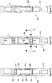
- FIGS 7A to 7C illustrate the internal detail of the pressure bypass arrangement 260.
- the pressure bypass arrangement 260 forms a part of the tool 10, and comprises an array of pressure bypass ports 264.
- Figure 7A illustrates the pressure bypass arrangement 260 in a normally closed configuration, meaning that a sleeve assembly 266 of the pressure bypass arrangement 260 is occluding the array of pressure bypass ports 264.
- the sleeve assembly 266 is partially housed in an annulus 268 formed between a shear sleeve 270 and an outer housing 272 of the pressure bypass arrangement, and partially housing in a central bore 280 of the pressure bypass arrangement 260.
- Spring 274 biases the sleeve 266 towards the closed position.
- the shear sleeve 270 is attached to a flapper valve assembly comprising a flapper valve 278 which can be opened to allow fluid through the central bore 280 of the pressure bypass arrangement 260 and closed to substantially block flow therethrough.
- the flapper valve 278 comprises a flapper aperture 282, in this example located in the centre thereof, to allow a reduced fluid flow therethrough.
- Figure 7B illustrates the pressure bypass arrangement 260 in a run-in configuration.
- fluid flowing in the uphole direction as a result of the tool 210 being run downhole impinges on the sleeve assembly 266 and flapper valve 278, and creates a build-up of pressure beneath the flapper valve 278.
- the sleeve assembly 266 moves in an uphole direction, compressing the spring 274. This has the effect of removing the occlusion to the pressure bypass ports 264 caused by the sleeve assembly 266 to allow fluid communication between the central bore 280 and the casing (not shown).
- a fluid in the central bore 280 is then permitted to flow from the central bore and into the casing in the direction of arrows D.
- some fluid is also permitted to continue to flow through the central bore 280 of the pressure bypass arrangement, in the direction of arrows E.
- the tool 210 may be run downhole more quickly.
- Figure 7C illustrates the pressure bypass arrangement 260 in a circulating configuration.
- the tool 210 may be used to circulate a fluid in a well (not shown).
- fluid is flowing in the downhole direction, as illustrated by arrows F, through the central bore 280 of the pressure bypass arrangement, and flapper valve 278 is opened.
- the downhole flow of fluid causes spring 274 to bias the sleeve assembly 266 towards the downhole direction, thereby closing the array of pressure bypass ports 264.
- the pressure bypass arrangement 260 may improve the safety of operation of the tool 10 by allowing the tool to react more preferably to sudden influxes, or kicks, of pressurised fluid in a well.
- a sudden influx of pressure into the pressure bypass arrangement may create a brief flow of fluid in the uphole direction through the pressure bypass arrangement.
- Such an up-flow of fluid may act on the sleeve assembly 266 in an uphole direction to open pressure bypass ports 264, thus allowing the pressurised fluid to escape from the tool 210 and into the casing (not shown).
- an operator may be able to avoid an influx of pressure physically moving the tool 10, and the entire associated tool string, back uphole, as sudden uphole movement of the tool string may cause safety concerns at the surface of the well.
Landscapes
- Engineering & Computer Science (AREA)
- Geology (AREA)
- Life Sciences & Earth Sciences (AREA)
- Mining & Mineral Resources (AREA)
- Environmental & Geological Engineering (AREA)
- Fluid Mechanics (AREA)
- Physics & Mathematics (AREA)
- General Life Sciences & Earth Sciences (AREA)
- Geochemistry & Mineralogy (AREA)
- Mechanical Engineering (AREA)
- Cleaning In General (AREA)
- Earth Drilling (AREA)
- Processing Of Solid Wastes (AREA)
- Pipe Accessories (AREA)
- Cleaning By Liquid Or Steam (AREA)
Claims (15)
- Procédé de lavage d'un espace annulaire qui entoure au moins partiellement un tubage (40) dans un puits, comprenant les étapes suivantes :positionnement d'un outil (10) à l'intérieur d'un tubage d'un puits de forage (40) ;écoulement d'un fluide de lavage depuis une ouverture d'injection (16) sur l'outil (10) dans l'espace annulaire à travers une première ouverture du tubage (38a) dans le tubage (40);formation d'un zone d'afflux (23) à l'intérieur du tubage (40), ayant une pression réduite par rapport à l'espace annulaire, à l'aide d'un appareil de réduction de la pression (34), dans lequel l'appareil de réduction de la pression (34) comprend au moins une ouverture de fluide (32) disposée sur au moins une aube à extension hélicoïdale (36) configurée pour conférer une composante de vitesse hélicoïdale à un fluide opérationnel quand il passe à travers l'appareil de réduction de la pression (34) ;écoulement du fluide de lavage depuis l'espace annulaire et à l'intérieur de la zone d'afflux (23) du tubage (40) à travers une deuxième ouverture du tubage (38b) dans le tubage (40).
- Procédé selon la revendication 1, comprenant la réduction de la pression dans la zone d'afflux (23) en accroissant la vitesse du fluide de lavage dans celle-ci ; et/ou la fourniture d'un appareil de réduction de la pression sur l'outil pour faciliter l'établissement d'une vitesse accrue du fluide opérationnel dans le tubage pour réduire la pression dans la zone d'afflux ;comprenant en outre optionnellement l'écoulement du fluide opérationnel depuis une ouverture de fluide (16) dans l'appareil de réduction de la pression (34), pour établir un tourbillon de fluide ;dans lequel l'ouverture de fluide (16) établit en outre optionnellement une direction de l'écoulement de fluide opérationnel à partir de celle-ci.
- Procédé selon la revendication 2, comprenant l'envoi du fluide opérationnel en utilisant l'au moins une aube (36) sur l'appareil de réduction de la pression (34).
- Procédé selon l'une quelconque des revendications précédentes, comprenant la perforation du tubage (40) pour former au moins une des première et deuxième ouvertures (38a, 38b) du tubage ; et/ou
comprenant la fourniture d'un agencement d'étanchéité (18, 20) entre l'outil (10) et le tubage pour restreindre l'écoulement du fluide de lavage dans le tubage (40), dans lequel l'agencement d'étanchéité (18, 20) est optionnellement positionné près de l'ouverture d'injection (16) sur l'outil (10). - Procédé selon l'une quelconque des revendications précédentes, comprenant l'écoulement d'un fluide qui réside à l'intérieur du tubage (40) à travers un agencement de dérivation dans l'outil (10) ; et/ou
comprenant l'écoulement du fluide de lavage depuis l'ouverture d'injection (16) et dans l'espace annulaire en même temps que l'outil (10) est déplacé par rapport au tubage (40). - Procédé selon l'une quelconque des revendications 1 à 5, comprenant les étapes suivantes :arrêt de l'écoulement du fluide de lavage depuis l'ouverture d'injection (16) ;déplacement de l'outil (10) vers un emplacement différent dans le tubage (40) ; etrétablissement de l'écoulement du fluide de lavage à travers l'ouverture d'injection (16);
- Procédé selon l'une quelconque des revendications précédentes, comprenant la mise en place d'un bouchon (28) en fond de trou de l'outil (10) ; et/ou
comprenant l'installation d'un bouchon (28) en fond de trou des première et deuxième ouvertures du tubage (38a, 38b). - Procédé selon l'une quelconque des revendications précédentes, comprenant l'utilisation de l'outil (10) pour exécuter des opérations de cimentation ; et/ou
comprenant la fourniture d'un agencement de dérivation de ciment (60, 62) sur l'outil (10), comprenant optionnellement l'écoulement du ciment à travers l'agencement de dérivation du ciment (60, 62) depuis une zone vers le haut de l'ouverture d'injection (16) et d'une zone en fond de trou de l'ouverture d'injection (16) ; comprenant en outre optionnellement le remplissage d'une zone du tubage (40) au-dessous de l'outil avec du ciment pour former un bouchon de ciment. - Procédé selon l'une quelconque des revendications précédentes, comprenant la fourniture d'un agencement de dérivation de la pression (260) ;dans lequel l'agencement de dérivation de la pression (260) fait optionnellement partie intégrante de l'outil (10) ; et/oudans lequel l'agencement de dérivation de la pression (260) comprend au moins un orifice de dérivation de la pression (264), dans lequel l'agencement de dérivation de la pression (260) comprend optionnellement un mécanisme d'actionnement pour ouvrir et fermer sélectivement l'orifice de dérivation de la pression (264).
- Appareil de fond de trou (10) pour laver un espace annulaire qui entoure au moins partiellement un tubage (40) dans un puits tel que décrit dans la revendication 1, comprenant :un boîtier externe (272) comportant un alésage (280) s'étendant à travers celui-ci ;un orifice d'injection de fluide positionné sur le boîtier, dans lequel un fluide de lavage est pompé à travers l'orifice d'injection de fluide (16) ; etun appareil de réduction de la pression (34) positionné vers le haut de l'orifice d'injection de fluide (16), l'appareil de réduction de la pression (34) étant configuré pour former une zone d'afflux (23) à l'intérieur du tubage (40), ayant une pression réduite par rapport à l'espace annulaire, dans lequel l'appareil de réduction de la pression (34) comprend au moins une ouverture de fluide (32) disposée sur au moins une aube à extension héliocoïdale (36), configurée pour conférer une composante de vitesse hélicoïdale à un fluide opérationnel lors de son passage à travers l'appareil de réduction de la pression (34) ; etun agencement d'étanchéité positionné près de l'ouverture d'injection sur l'appareil et entre l'appareil et le tubage, dans lequel, en service, le fluide de lavage s'écoule vers l'appareil de réduction de la pression (34) à travers l'espace annulaire pour laver l'espace annulaire dans le puits.
- Appareil de fond de trou (10) selon la revendication 10, dans lequel ladite au moins une aube (36) s'étend de manière hélicoïdale par rapport à l'axe de l'outil.
- Appareil de fond de trou (10) selon les revendications 10 ou 11, dans lequel l'agencement d'étanchéité comprend :un joint d'étanchéité supérieur (18) disposé en tête de puits de l'orifice d'injection de fluide (16) ; et/oucomprenant un joint d'étanchéité inférieur (20) disposé en fond de trou de l'orifice d'injection de fluide (16), comprenant optionnellement un agencement de dérivation (60, 62) comportant un orifice de dérivation vers le haut (60) positionné vers le haut du joint d'étanchéité supérieur (16) et un orifice de dérivation en fond de trou (62) positionné en fond de trou du joint d'étanchéité inférieur (20).
- Appareil de fond de trou selon l'une quelconque des revendications 10 à 12, comprenant un agencement de bouchon amovible (28) ; et/ouun agencement de siège de fléchette (24) disposé dans l'alésage (280) du boîtier (272) ; et/ouun agencement de dérivation de la pression (260).
- Procédé de bouchage d'un puits qui inclut un tubage de puits de forage (40) et un espace annulaire entourant au moins partiellement le tubage du puits (40) comprenant les étapes suivantes :lavage de l'espace annulaire qui entoure au moins partiellement un tubage (40) en appliquant le procédé selon la revendication 1 ; etfourniture d'un bouchon (28) dans le puits de forage.
- Procédé selon la revendication 14, comprenant la fourniture d'un bouchon (28) dans l'espace annulaire et à l'intérieur du tubage (40).
Applications Claiming Priority (2)
| Application Number | Priority Date | Filing Date | Title |
|---|---|---|---|
| GB1719216.2A GB2568529B (en) | 2017-11-20 | 2017-11-20 | Method and apparatus for washing an annulus |
| PCT/GB2018/053345 WO2019097259A1 (fr) | 2017-11-20 | 2018-11-19 | Procédé et appareil de nettoyage d'un espace annulaire |
Publications (2)
| Publication Number | Publication Date |
|---|---|
| EP3714130A1 EP3714130A1 (fr) | 2020-09-30 |
| EP3714130B1 true EP3714130B1 (fr) | 2022-08-31 |
Family
ID=60805593
Family Applications (1)
| Application Number | Title | Priority Date | Filing Date |
|---|---|---|---|
| EP18808092.3A Active EP3714130B1 (fr) | 2017-11-20 | 2018-11-19 | Procédé et appareil de nettoyage d'un espace annulaire |
Country Status (7)
| Country | Link |
|---|---|
| US (1) | US11261704B2 (fr) |
| EP (1) | EP3714130B1 (fr) |
| AU (1) | AU2018369713B2 (fr) |
| CA (1) | CA3082964C (fr) |
| GB (1) | GB2568529B (fr) |
| MY (1) | MY202580A (fr) |
| WO (1) | WO2019097259A1 (fr) |
Families Citing this family (17)
| Publication number | Priority date | Publication date | Assignee | Title |
|---|---|---|---|---|
| GB201918328D0 (en) | 2019-12-12 | 2020-01-29 | Morgan Mike | Downhole tool and methods |
| US11242734B2 (en) * | 2020-01-10 | 2022-02-08 | Baker Hughes Oilfield Operations Llc | Fluid retrieval using annular cleaning system |
| NO346617B1 (en) | 2020-03-09 | 2022-10-31 | Hydra Systems As | A fluid diverter tool, system and method of diverting a fluid flow in a well |
| CN114439432B (zh) * | 2020-10-20 | 2024-03-22 | 中国石油化工股份有限公司 | 液压整形充填防砂一体化管柱及方法 |
| GB202019133D0 (en) * | 2020-12-04 | 2021-01-20 | Hrg Well Solutions Ltd | Annulus remediation system and method |
| US11519241B2 (en) * | 2021-02-18 | 2022-12-06 | Saudi Arabian Oil Company | Drill assembly having a stinger with downward oriented cups |
| US12163400B2 (en) * | 2021-03-29 | 2024-12-10 | Conocophillips Company | Plug and abandon operation in a hydrocarbon well by cementing the annulus through apertures in the casing |
| NO346353B1 (en) * | 2021-05-11 | 2022-06-20 | Archer Oiltools As | Toolstring and method for inner casing perforating, shattering annulus cement, and washing the first annulus in a second casing, and cementing said annulus, and a tool therefor |
| CN115898308B (zh) * | 2021-08-11 | 2024-12-27 | 中国石油天然气股份有限公司 | 固井水泥的清理装置及方法 |
| US11702914B1 (en) * | 2022-03-29 | 2023-07-18 | Saudi Arabian Oil Company | Sand flushing above blanking plug |
| US11867021B2 (en) * | 2022-04-27 | 2024-01-09 | Saudi Arabian Oil Company | Off-bottom cementing pod |
| CN115126450B (zh) * | 2022-08-31 | 2022-11-22 | 山东普瑞思德石油技术有限公司 | 一种带自复位与原位置反洗井功能的底部充填工具 |
| CN116446827B (zh) * | 2023-06-16 | 2024-06-28 | 山东普瑞思德石油技术有限公司 | 一种可自调底部充填工具 |
| CN116498232B (zh) * | 2023-06-28 | 2023-09-19 | 北京城建集团有限责任公司 | 一种回灌井洗井装置和回灌井系统 |
| NO20240039A1 (en) * | 2024-01-12 | 2025-07-14 | Archer Oiltools As | Downhole washing tool |
| NO349368B1 (en) * | 2024-03-08 | 2025-12-22 | Archer Oiltools As | Validation of a well annulus washing operation |
| NO349712B1 (en) * | 2024-06-14 | 2026-04-13 | Archer Oiltools As | A method for use in a well intervention and an apparatus for a well intervention. |
Family Cites Families (9)
| Publication number | Priority date | Publication date | Assignee | Title |
|---|---|---|---|---|
| US3367420A (en) * | 1966-03-07 | 1968-02-06 | Gulf Research Development Co | Method of consolidation of incompetent subsurface formations |
| NO335972B1 (no) * | 2011-01-12 | 2015-04-07 | Hydra Systems As | Fremgangsmåte for kombinert rengjøring og plugging i en brønn, vaskeverktøy for retningsstyrt spyling i en brønn, samt anvendelse av vaskeverktøyet |
| NO335153B1 (no) * | 2011-02-03 | 2014-10-06 | Tco As | Verktøy og fremgangsmåte for avstenging av en brønn |
| US9222323B2 (en) * | 2013-01-14 | 2015-12-29 | Archer Oil Tools As | Petroleum well drill—or coiled tubing string mounted fishing tool |
| DK3036395T3 (da) * | 2013-08-21 | 2017-11-06 | Archer Oiltools As | Et-trins-perforerings- og vaskeværktøj for lukning og exit fra borehuller (plug and abandonment, P & A) |
| US9334712B2 (en) * | 2013-08-21 | 2016-05-10 | Archer Oil Tools As | One trip perforating and washing tool for plugging and abandoning wells |
| NO339191B1 (no) * | 2013-09-06 | 2016-11-14 | Hydra Systems As | Fremgangsmåte for isolering av en permeabel sone i en underjordisk brønn |
| NO20140029A1 (no) * | 2014-01-10 | 2015-07-13 | Archer Oil Tools As | Fremgangsmåte og anordning for kutting, perforering, vasking og trekking av fôringsrør i en brønn |
| AU2016415289B2 (en) | 2016-07-21 | 2021-09-23 | Landmark Graphics Corporation | Method for slim hole single trip remedial or plug and abandonment cement barrier |
-
2017
- 2017-11-20 GB GB1719216.2A patent/GB2568529B/en active Active
-
2018
- 2018-11-19 US US16/764,876 patent/US11261704B2/en active Active
- 2018-11-19 CA CA3082964A patent/CA3082964C/fr active Active
- 2018-11-19 MY MYPI2020002434A patent/MY202580A/en unknown
- 2018-11-19 EP EP18808092.3A patent/EP3714130B1/fr active Active
- 2018-11-19 AU AU2018369713A patent/AU2018369713B2/en active Active
- 2018-11-19 WO PCT/GB2018/053345 patent/WO2019097259A1/fr not_active Ceased
Also Published As
| Publication number | Publication date |
|---|---|
| CA3082964C (fr) | 2025-06-17 |
| US20200340332A1 (en) | 2020-10-29 |
| EP3714130A1 (fr) | 2020-09-30 |
| GB2568529B (en) | 2021-02-24 |
| GB2568529A (en) | 2019-05-22 |
| AU2018369713A1 (en) | 2020-06-11 |
| US11261704B2 (en) | 2022-03-01 |
| CA3082964A1 (fr) | 2019-05-23 |
| AU2018369713B2 (en) | 2023-11-09 |
| MY202580A (en) | 2024-05-09 |
| GB201719216D0 (en) | 2018-01-03 |
| WO2019097259A1 (fr) | 2019-05-23 |
Similar Documents
| Publication | Publication Date | Title |
|---|---|---|
| CA3082964C (fr) | Procédé et appareil de nettoyage d’un espace annulaire | |
| US20190353006A1 (en) | Tools and methods for use in completion of a wellbore | |
| CN103201454B (zh) | 多功能隔离工具及使用方法 | |
| CA2916480C (fr) | Appareil et procede de forage et de raclage de tubage en une seule manuvre | |
| CA3077883C (fr) | Outillage de fond avec securite pour debris, et methode d'utilisation | |
| NO20190541A1 (en) | Frac and gravel packing system having return path and method | |
| CA2799967A1 (fr) | Outil de traitement de fluide de fond de trou | |
| CA2820704A1 (fr) | Vanne de fracturation | |
| DK2935771T3 (en) | METHOD AND DEVICE FOR TREATING AN UNDERGROUND AREA | |
| CA3046814A1 (fr) | Ensemble d'outil et procede de forage de puits ramifies et multilateraux avec sifflet deviateur | |
| CA2901074A1 (fr) | Dispositif de manchon servant aux operations de completion de trou de forage | |
| NO20231046A1 (en) | Open hole multi-zone single trip completion system |
Legal Events
| Date | Code | Title | Description |
|---|---|---|---|
| STAA | Information on the status of an ep patent application or granted ep patent |
Free format text: STATUS: UNKNOWN |
|
| STAA | Information on the status of an ep patent application or granted ep patent |
Free format text: STATUS: THE INTERNATIONAL PUBLICATION HAS BEEN MADE |
|
| PUAI | Public reference made under article 153(3) epc to a published international application that has entered the european phase |
Free format text: ORIGINAL CODE: 0009012 |
|
| STAA | Information on the status of an ep patent application or granted ep patent |
Free format text: STATUS: REQUEST FOR EXAMINATION WAS MADE |
|
| 17P | Request for examination filed |
Effective date: 20200515 |
|
| AK | Designated contracting states |
Kind code of ref document: A1 Designated state(s): AL AT BE BG CH CY CZ DE DK EE ES FI FR GB GR HR HU IE IS IT LI LT LU LV MC MK MT NL NO PL PT RO RS SE SI SK SM TR |
|
| AX | Request for extension of the european patent |
Extension state: BA ME |
|
| DAV | Request for validation of the european patent (deleted) | ||
| DAX | Request for extension of the european patent (deleted) | ||
| STAA | Information on the status of an ep patent application or granted ep patent |
Free format text: STATUS: EXAMINATION IS IN PROGRESS |
|
| 17Q | First examination report despatched |
Effective date: 20210601 |
|
| GRAP | Despatch of communication of intention to grant a patent |
Free format text: ORIGINAL CODE: EPIDOSNIGR1 |
|
| STAA | Information on the status of an ep patent application or granted ep patent |
Free format text: STATUS: GRANT OF PATENT IS INTENDED |
|
| INTG | Intention to grant announced |
Effective date: 20220517 |
|
| GRAS | Grant fee paid |
Free format text: ORIGINAL CODE: EPIDOSNIGR3 |
|
| GRAA | (expected) grant |
Free format text: ORIGINAL CODE: 0009210 |
|
| STAA | Information on the status of an ep patent application or granted ep patent |
Free format text: STATUS: THE PATENT HAS BEEN GRANTED |
|
| RBV | Designated contracting states (corrected) |
Designated state(s): AL AT BE BG CH CY CZ DE DK EE ES FI FR GR HR HU IE IS IT LI LT LU LV MC MK MT NL NO PL PT RO RS SE SI SK SM TR |
|
| AK | Designated contracting states |
Kind code of ref document: B1 Designated state(s): AL AT BE BG CH CY CZ DE DK EE ES FI FR GR HR HU IE IS IT LI LT LU LV MC MK MT NL NO PL PT RO RS SE SI SK SM TR |
|
| REG | Reference to a national code |
Ref country code: CH Ref legal event code: EP |
|
| REG | Reference to a national code |
Ref country code: AT Ref legal event code: REF Ref document number: 1515411 Country of ref document: AT Kind code of ref document: T Effective date: 20220915 |
|
| REG | Reference to a national code |
Ref country code: DE Ref legal event code: R096 Ref document number: 602018040083 Country of ref document: DE |
|
| REG | Reference to a national code |
Ref country code: IE Ref legal event code: FG4D |
|
| REG | Reference to a national code |
Ref country code: NL Ref legal event code: FP |
|
| REG | Reference to a national code |
Ref country code: NO Ref legal event code: T2 Effective date: 20220831 |
|
| REG | Reference to a national code |
Ref country code: LT Ref legal event code: MG9D |
|
| PG25 | Lapsed in a contracting state [announced via postgrant information from national office to epo] |
Ref country code: SE Free format text: LAPSE BECAUSE OF FAILURE TO SUBMIT A TRANSLATION OF THE DESCRIPTION OR TO PAY THE FEE WITHIN THE PRESCRIBED TIME-LIMIT Effective date: 20220831 Ref country code: RS Free format text: LAPSE BECAUSE OF FAILURE TO SUBMIT A TRANSLATION OF THE DESCRIPTION OR TO PAY THE FEE WITHIN THE PRESCRIBED TIME-LIMIT Effective date: 20220831 Ref country code: LV Free format text: LAPSE BECAUSE OF FAILURE TO SUBMIT A TRANSLATION OF THE DESCRIPTION OR TO PAY THE FEE WITHIN THE PRESCRIBED TIME-LIMIT Effective date: 20220831 Ref country code: LT Free format text: LAPSE BECAUSE OF FAILURE TO SUBMIT A TRANSLATION OF THE DESCRIPTION OR TO PAY THE FEE WITHIN THE PRESCRIBED TIME-LIMIT Effective date: 20220831 Ref country code: FI Free format text: LAPSE BECAUSE OF FAILURE TO SUBMIT A TRANSLATION OF THE DESCRIPTION OR TO PAY THE FEE WITHIN THE PRESCRIBED TIME-LIMIT Effective date: 20220831 |
|
| REG | Reference to a national code |
Ref country code: AT Ref legal event code: MK05 Ref document number: 1515411 Country of ref document: AT Kind code of ref document: T Effective date: 20220831 |
|
| PG25 | Lapsed in a contracting state [announced via postgrant information from national office to epo] |
Ref country code: PL Free format text: LAPSE BECAUSE OF FAILURE TO SUBMIT A TRANSLATION OF THE DESCRIPTION OR TO PAY THE FEE WITHIN THE PRESCRIBED TIME-LIMIT Effective date: 20220831 Ref country code: IS Free format text: LAPSE BECAUSE OF FAILURE TO SUBMIT A TRANSLATION OF THE DESCRIPTION OR TO PAY THE FEE WITHIN THE PRESCRIBED TIME-LIMIT Effective date: 20221231 Ref country code: HR Free format text: LAPSE BECAUSE OF FAILURE TO SUBMIT A TRANSLATION OF THE DESCRIPTION OR TO PAY THE FEE WITHIN THE PRESCRIBED TIME-LIMIT Effective date: 20220831 Ref country code: GR Free format text: LAPSE BECAUSE OF FAILURE TO SUBMIT A TRANSLATION OF THE DESCRIPTION OR TO PAY THE FEE WITHIN THE PRESCRIBED TIME-LIMIT Effective date: 20221201 |
|
| PG25 | Lapsed in a contracting state [announced via postgrant information from national office to epo] |
Ref country code: SM Free format text: LAPSE BECAUSE OF FAILURE TO SUBMIT A TRANSLATION OF THE DESCRIPTION OR TO PAY THE FEE WITHIN THE PRESCRIBED TIME-LIMIT Effective date: 20220831 Ref country code: RO Free format text: LAPSE BECAUSE OF FAILURE TO SUBMIT A TRANSLATION OF THE DESCRIPTION OR TO PAY THE FEE WITHIN THE PRESCRIBED TIME-LIMIT Effective date: 20220831 Ref country code: PT Free format text: LAPSE BECAUSE OF FAILURE TO SUBMIT A TRANSLATION OF THE DESCRIPTION OR TO PAY THE FEE WITHIN THE PRESCRIBED TIME-LIMIT Effective date: 20230102 Ref country code: ES Free format text: LAPSE BECAUSE OF FAILURE TO SUBMIT A TRANSLATION OF THE DESCRIPTION OR TO PAY THE FEE WITHIN THE PRESCRIBED TIME-LIMIT Effective date: 20220831 Ref country code: DK Free format text: LAPSE BECAUSE OF FAILURE TO SUBMIT A TRANSLATION OF THE DESCRIPTION OR TO PAY THE FEE WITHIN THE PRESCRIBED TIME-LIMIT Effective date: 20220831 Ref country code: CZ Free format text: LAPSE BECAUSE OF FAILURE TO SUBMIT A TRANSLATION OF THE DESCRIPTION OR TO PAY THE FEE WITHIN THE PRESCRIBED TIME-LIMIT Effective date: 20220831 Ref country code: AT Free format text: LAPSE BECAUSE OF FAILURE TO SUBMIT A TRANSLATION OF THE DESCRIPTION OR TO PAY THE FEE WITHIN THE PRESCRIBED TIME-LIMIT Effective date: 20220831 |
|
| PG25 | Lapsed in a contracting state [announced via postgrant information from national office to epo] |
Ref country code: SK Free format text: LAPSE BECAUSE OF FAILURE TO SUBMIT A TRANSLATION OF THE DESCRIPTION OR TO PAY THE FEE WITHIN THE PRESCRIBED TIME-LIMIT Effective date: 20220831 Ref country code: EE Free format text: LAPSE BECAUSE OF FAILURE TO SUBMIT A TRANSLATION OF THE DESCRIPTION OR TO PAY THE FEE WITHIN THE PRESCRIBED TIME-LIMIT Effective date: 20220831 |
|
| REG | Reference to a national code |
Ref country code: DE Ref legal event code: R119 Ref document number: 602018040083 Country of ref document: DE Ref country code: DE Ref legal event code: R097 Ref document number: 602018040083 Country of ref document: DE |
|
| PG25 | Lapsed in a contracting state [announced via postgrant information from national office to epo] |
Ref country code: MC Free format text: LAPSE BECAUSE OF FAILURE TO SUBMIT A TRANSLATION OF THE DESCRIPTION OR TO PAY THE FEE WITHIN THE PRESCRIBED TIME-LIMIT Effective date: 20220831 Ref country code: AL Free format text: LAPSE BECAUSE OF FAILURE TO SUBMIT A TRANSLATION OF THE DESCRIPTION OR TO PAY THE FEE WITHIN THE PRESCRIBED TIME-LIMIT Effective date: 20220831 |
|
| REG | Reference to a national code |
Ref country code: CH Ref legal event code: PL |
|
| PLBE | No opposition filed within time limit |
Free format text: ORIGINAL CODE: 0009261 |
|
| STAA | Information on the status of an ep patent application or granted ep patent |
Free format text: STATUS: NO OPPOSITION FILED WITHIN TIME LIMIT |
|
| REG | Reference to a national code |
Ref country code: BE Ref legal event code: MM Effective date: 20221130 |
|
| PG25 | Lapsed in a contracting state [announced via postgrant information from national office to epo] |
Ref country code: LI Free format text: LAPSE BECAUSE OF NON-PAYMENT OF DUE FEES Effective date: 20221130 Ref country code: CH Free format text: LAPSE BECAUSE OF NON-PAYMENT OF DUE FEES Effective date: 20221130 |
|
| 26N | No opposition filed |
Effective date: 20230601 |
|
| PG25 | Lapsed in a contracting state [announced via postgrant information from national office to epo] |
Ref country code: SI Free format text: LAPSE BECAUSE OF FAILURE TO SUBMIT A TRANSLATION OF THE DESCRIPTION OR TO PAY THE FEE WITHIN THE PRESCRIBED TIME-LIMIT Effective date: 20220831 Ref country code: LU Free format text: LAPSE BECAUSE OF NON-PAYMENT OF DUE FEES Effective date: 20221119 |
|
| P01 | Opt-out of the competence of the unified patent court (upc) registered |
Effective date: 20230908 |
|
| PG25 | Lapsed in a contracting state [announced via postgrant information from national office to epo] |
Ref country code: IE Free format text: LAPSE BECAUSE OF NON-PAYMENT OF DUE FEES Effective date: 20221119 Ref country code: DE Free format text: LAPSE BECAUSE OF NON-PAYMENT OF DUE FEES Effective date: 20230601 |
|
| PG25 | Lapsed in a contracting state [announced via postgrant information from national office to epo] |
Ref country code: FR Free format text: LAPSE BECAUSE OF NON-PAYMENT OF DUE FEES Effective date: 20221130 Ref country code: BE Free format text: LAPSE BECAUSE OF NON-PAYMENT OF DUE FEES Effective date: 20221130 |
|
| PG25 | Lapsed in a contracting state [announced via postgrant information from national office to epo] |
Ref country code: CY Free format text: LAPSE BECAUSE OF FAILURE TO SUBMIT A TRANSLATION OF THE DESCRIPTION OR TO PAY THE FEE WITHIN THE PRESCRIBED TIME-LIMIT Effective date: 20220831 |
|
| PG25 | Lapsed in a contracting state [announced via postgrant information from national office to epo] |
Ref country code: MK Free format text: LAPSE BECAUSE OF FAILURE TO SUBMIT A TRANSLATION OF THE DESCRIPTION OR TO PAY THE FEE WITHIN THE PRESCRIBED TIME-LIMIT Effective date: 20220831 Ref country code: IT Free format text: LAPSE BECAUSE OF FAILURE TO SUBMIT A TRANSLATION OF THE DESCRIPTION OR TO PAY THE FEE WITHIN THE PRESCRIBED TIME-LIMIT Effective date: 20220831 Ref country code: HU Free format text: LAPSE BECAUSE OF FAILURE TO SUBMIT A TRANSLATION OF THE DESCRIPTION OR TO PAY THE FEE WITHIN THE PRESCRIBED TIME-LIMIT; INVALID AB INITIO Effective date: 20181119 |
|
| PG25 | Lapsed in a contracting state [announced via postgrant information from national office to epo] |
Ref country code: BG Free format text: LAPSE BECAUSE OF FAILURE TO SUBMIT A TRANSLATION OF THE DESCRIPTION OR TO PAY THE FEE WITHIN THE PRESCRIBED TIME-LIMIT Effective date: 20220831 |
|
| PG25 | Lapsed in a contracting state [announced via postgrant information from national office to epo] |
Ref country code: MT Free format text: LAPSE BECAUSE OF FAILURE TO SUBMIT A TRANSLATION OF THE DESCRIPTION OR TO PAY THE FEE WITHIN THE PRESCRIBED TIME-LIMIT Effective date: 20220831 |
|
| PGFP | Annual fee paid to national office [announced via postgrant information from national office to epo] |
Ref country code: NL Payment date: 20251003 Year of fee payment: 8 |
|
| PG25 | Lapsed in a contracting state [announced via postgrant information from national office to epo] |
Ref country code: TR Free format text: LAPSE BECAUSE OF FAILURE TO SUBMIT A TRANSLATION OF THE DESCRIPTION OR TO PAY THE FEE WITHIN THE PRESCRIBED TIME-LIMIT Effective date: 20220831 |
|
| PGFP | Annual fee paid to national office [announced via postgrant information from national office to epo] |
Ref country code: NO Payment date: 20251113 Year of fee payment: 8 |