EP3714468B1 - Filterentlüftung für becken mit verbrauchtem brennstoff eines reaktorsicherheitsbehälters - Google Patents
Filterentlüftung für becken mit verbrauchtem brennstoff eines reaktorsicherheitsbehälters Download PDFInfo
- Publication number
- EP3714468B1 EP3714468B1 EP18881147.5A EP18881147A EP3714468B1 EP 3714468 B1 EP3714468 B1 EP 3714468B1 EP 18881147 A EP18881147 A EP 18881147A EP 3714468 B1 EP3714468 B1 EP 3714468B1
- Authority
- EP
- European Patent Office
- Prior art keywords
- spent fuel
- containment
- pool
- effluent
- water pool
- Prior art date
- Legal status (The legal status is an assumption and is not a legal conclusion. Google has not performed a legal analysis and makes no representation as to the accuracy of the status listed.)
- Active
Links
Images
Classifications
-
- G—PHYSICS
- G21—NUCLEAR PHYSICS; NUCLEAR ENGINEERING
- G21C—NUCLEAR REACTORS
- G21C13/00—Pressure vessels; Containment vessels; Containment in general
- G21C13/02—Details
- G21C13/022—Ventilating arrangements
-
- G—PHYSICS
- G21—NUCLEAR PHYSICS; NUCLEAR ENGINEERING
- G21C—NUCLEAR REACTORS
- G21C9/00—Emergency protection arrangements structurally associated with the reactor, e.g. safety valves provided with pressure equalisation devices
- G21C9/004—Pressure suppression
-
- G—PHYSICS
- G21—NUCLEAR PHYSICS; NUCLEAR ENGINEERING
- G21C—NUCLEAR REACTORS
- G21C13/00—Pressure vessels; Containment vessels; Containment in general
- G21C13/10—Means for preventing contamination in the event of leakage, e.g. double wall
-
- G—PHYSICS
- G21—NUCLEAR PHYSICS; NUCLEAR ENGINEERING
- G21C—NUCLEAR REACTORS
- G21C19/00—Arrangements for treating, for handling, or for facilitating the handling of, fuel or other materials which are used within the reactor, e.g. within its pressure vessel
-
- G—PHYSICS
- G21—NUCLEAR PHYSICS; NUCLEAR ENGINEERING
- G21C—NUCLEAR REACTORS
- G21C19/00—Arrangements for treating, for handling, or for facilitating the handling of, fuel or other materials which are used within the reactor, e.g. within its pressure vessel
- G21C19/02—Details of handling arrangements
- G21C19/06—Magazines for holding fuel elements or control elements
- G21C19/07—Storage racks; Storage pools
-
- G—PHYSICS
- G21—NUCLEAR PHYSICS; NUCLEAR ENGINEERING
- G21C—NUCLEAR REACTORS
- G21C19/00—Arrangements for treating, for handling, or for facilitating the handling of, fuel or other materials which are used within the reactor, e.g. within its pressure vessel
- G21C19/28—Arrangements for introducing fluent material into the reactor core; Arrangements for removing fluent material from the reactor core
- G21C19/30—Arrangements for introducing fluent material into the reactor core; Arrangements for removing fluent material from the reactor core with continuous purification of circulating fluent material, e.g. by extraction of fission products deterioration or corrosion products, impurities, e.g. by cold traps
- G21C19/303—Arrangements for introducing fluent material into the reactor core; Arrangements for removing fluent material from the reactor core with continuous purification of circulating fluent material, e.g. by extraction of fission products deterioration or corrosion products, impurities, e.g. by cold traps specially adapted for gases
-
- G—PHYSICS
- G21—NUCLEAR PHYSICS; NUCLEAR ENGINEERING
- G21C—NUCLEAR REACTORS
- G21C19/00—Arrangements for treating, for handling, or for facilitating the handling of, fuel or other materials which are used within the reactor, e.g. within its pressure vessel
- G21C19/28—Arrangements for introducing fluent material into the reactor core; Arrangements for removing fluent material from the reactor core
- G21C19/30—Arrangements for introducing fluent material into the reactor core; Arrangements for removing fluent material from the reactor core with continuous purification of circulating fluent material, e.g. by extraction of fission products deterioration or corrosion products, impurities, e.g. by cold traps
- G21C19/307—Arrangements for introducing fluent material into the reactor core; Arrangements for removing fluent material from the reactor core with continuous purification of circulating fluent material, e.g. by extraction of fission products deterioration or corrosion products, impurities, e.g. by cold traps specially adapted for liquids
-
- Y—GENERAL TAGGING OF NEW TECHNOLOGICAL DEVELOPMENTS; GENERAL TAGGING OF CROSS-SECTIONAL TECHNOLOGIES SPANNING OVER SEVERAL SECTIONS OF THE IPC; TECHNICAL SUBJECTS COVERED BY FORMER USPC CROSS-REFERENCE ART COLLECTIONS [XRACs] AND DIGESTS
- Y02—TECHNOLOGIES OR APPLICATIONS FOR MITIGATION OR ADAPTATION AGAINST CLIMATE CHANGE
- Y02E—REDUCTION OF GREENHOUSE GAS [GHG] EMISSIONS, RELATED TO ENERGY GENERATION, TRANSMISSION OR DISTRIBUTION
- Y02E30/00—Energy generation of nuclear origin
- Y02E30/30—Nuclear fission reactors
Definitions
- This invention pertains in general to nuclear reactor containment systems, and, more particularly, to nuclear reactor containment ventilation filtration systems for safely reducing pressure buildup within a containment without the release of harmful contaminants.
- nuclear power plants must be designed to ensure that even in the event of accidents, a mechanism will be provided to prevent or minimize the escape of radioactive material and noble gases.
- the reactor system is typically housed within a primary containment structure that is constructed from steel and reinforced concrete.
- the primary containment vessel is designed to be capable of withstanding large pressures which may result from various postulated accident scenarios. However, if a scenario is postulated to be sufficiently severe, the containment vessel itself could fail from gradually increasing pressure. Although the likelihood of such an event is considered very small, the health risks associated with exposing the surrounding population to the radioactive releases of such an event has led many to believe that a mechanism should be provided to vent the containment in a controlled manner and filter the gases to minimize the release of radioactivity. That is, it is desirable to both provide a pressure release device for the containment vessel and a mechanism for filtering any gases that may be released by the containment before they are released into the atmosphere.
- Leach discloses a fission product scrubbing system for a nuclear reactor. Specifically, a second compartment in fluid communication with the containment is partially filled with water. In the event of a large pressure increase, a ruptured disc disposed within a vent pipe emanating from the secondary compartment bursts to relieve pressure. When the rupture disc blows, radioactive gases and vapors from the containment pass through the water filled secondary compartment and are then released through the now open vent pipe.
- the document US 2015/194226 discloses an apparatus for suppressing containment pressure of a PWR type nuclear reactor.
- the apparatus known from D1 comprises large volume of water making up the spent fuel pool in order to ensure that spent fuel remains submerged even in an event of prolonged interruption of the outside water supply.
- the apparatus requires short length of a piping to flow steam from reactor containment into the spent fuel pool since the spent fuel pool is located close to the serviced nuclear reactor.
- the apparatus can place the filters at the inlets to enable clean-up process by replacing only the filters at the inlets of the contaminated reactor radiological containment structure.
- US 2015/194226 does not disclose a chemical injection system configured to release a chemical into the spent fuel storage water pool to facilitate a reaction with the atmospheric effluent to be released to substantially neuter any deleterious environmental impact of the atmospheric effluent to be released.
- This invention provides a filtered venting system for a nuclear power generating facility having a containment for housing a nuclear reactor and for confining radiation leaked from the nuclear reactor.
- the containment has a ventilation outlet for providing a controlled release to the environment surrounding the containment, for an atmospheric pressure buildup within the containment in the event the pressure of an atmospheric effluent within the containment is built up to a level that exceeded a preselected value.
- the nuclear power generating facility also has, outside the containment, an associated spent fuel storage water pool, including a filter system for filtering contaminants released from or on route to the ventilation outlet.
- the filter system includes a dedicated piping system that is connected between an interior of the containment or the ventilation outlet and the spent fuel storage water pool, for fluidly communicating any atmospheric effluent to be released from inside of the containment through the spent fuel storage water pool.
- the filter system also includes one or more valves connected to the dedicated piping system for controlling the release of the atmospheric effluent to be released; and a chemical injection system configured to release a chemical into the spent fuel storage water pool to facilitate a reaction with the atmospheric effluent to be released to substantially neuter any deleterious environmental impact of the atmospheric effluent to be released.
- a control system is connected to one or more of the chemical injection systems and/or the one or more of the valves and is configured to control the release of the chemical and/or the release of the atmospheric effluent.
- the dedicated piping system includes a check valve configured to prevent spent fuel pool water from being drawn into the containment.
- the control system includes a manually actuated, remotely operated valve(s) in the dedicated piping system, the valve(s) being configured to isolate the dedicated vent piping under normal operating conditions, unless activated.
- this configuration of valve(s) for isolation will be located outside of the containment building and will comply with the regulated requirements for isolation of piping that penetrates a containment building.
- the manually actuated, remote operated valve(s) is configured in the dedicated piping system to be in parallel with a passively operated valve structured to release the atmospheric effluent to the spent fuel water pool if a pressure is sensed within the containment in excess of a given pressure.
- the dedicated piping system has an outlet in a lower portion of the spent fuel water pool that releases the atmospheric effluent to the spent fuel water pool through a sparger.
- the chemical injection system releases the chemical into the spent fuel water pool through a chemical injection header that is supported just above the sparger within the spent fuel storage water pool.
- the chemical injection header and the sparger are supported within the spent fuel storage water pool at an elevation below the area that is used to transfer fuel into and out of the spent fuel storage water pool and, preferably, as low as possible to maximize transit time of the released effluent through the water pool.
- the invention also contemplates a method for operating such a filter system that includes the step of sensing a pressure buildup within the nuclear containment.
- the method routs a portion of the atmospheric effluent through the spent fuel pool when the pressure buildup within the containment reaches a preselected value and releases a chemical into the spent fuel pool to facilitate a reaction with the effluent to be released to substantially neuter any deleterious environmental impact of the effluent to be released.
- the routing step and the releasing step are performed at the same time and the atmospheric effluent is introduced into water in the spent fuel pool through a sparger supported near or at a bottom of the spent fuel pool.
- the releasing step releases the chemical into water within the spent fuel pool at an elevation near the bottom of the spent fuel pool just above the sparger.
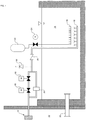
- Figure 1 is a schematic view of a reactor containment building spent fuel pool filter vent in accordance with this invention.
- This invention involves an application specific design of piping, valves, control logic and a chemical injection system to effectively employ the concepts of a wet filtered vent design, such as the one described in U.S. Patent No. 9,502,144 , without the addition of a wet filter vent filtration tank.
- a wet filtered vent design such as the one described in U.S. Patent No. 9,502,144
- FIG 1 shows a schematic representation of a portion of a nuclear containment and adjacent spent fuel pool.
- This invention uses ventilation piping 10 that directs a pressure relief discharge from the containment vessel 12 into the plant's existing spent fuel pool 14 through an engineered sparger design (or existing spent fuel pool cooling system sparger) 16. Isolation of the ventilation piping is achieved via conventional, remotely operated valve(s) 18, controlled to open by manual actuation by the plant operator.
- An alternate bypass system with passive pressure relief valve 20, is available in the event of an operator error or mechanical failure of the isolation valve(s) 18.
- the bypass system automatically opens the valve 20, which is a passive pressure relief device, if a preselected pressure is sensed in the containment.
- the contaminated aerosol release will be filtered via the spent fuel pool inventory, which will be treated with conventional wet filtration chemistry control via a passive chemical injection system 22 for gas (e.g., iodine, cesium, xenon) and fission product particulates removal.
- gas e.g., iodine, cesium, xenon
- the chemicals will be released into the pool inventory simultaneous with the ventilation release to the pool (i.e., opening of the ventilation isolation valves 18 or 20) via a controlled opening of the chemical injection system isolation valve 24.
- the chemicals will be injected directly above the sparger outlets 16 via a chemical injection header 26.
- the chemical injection header and the sparger are supported in the spent fuel pool at an elevation, preferably, as low as possible in the pool and below the operating level necessary for fuel transfer into and out of the pool.
- the chemical injection header 26 is, preferably, positioned just above and over the sparger 16.
Landscapes
- Physics & Mathematics (AREA)
- Engineering & Computer Science (AREA)
- Plasma & Fusion (AREA)
- General Engineering & Computer Science (AREA)
- High Energy & Nuclear Physics (AREA)
- Structure Of Emergency Protection For Nuclear Reactors (AREA)
Claims (11)
- Nukleare Energieerzeugungsanlage mit einem Sicherheitsbehälter (12) zur Einhausung eines Kernreaktors und zur Eindämmung von Strahlung, die aus dem Kernreaktor austritt, wobei der Sicherheitsbehälter einen Entlüftungsauslass (10) aufweist, um in dem Fall, dass der Druck eines atmosphärischen Effluenten sich bis zu einem Niveau aufbaut, das einen vorgewählten Wert überschritten hat, eine kontrollierte Freisetzung für einen innerhalb des Sicherheitsbehälters aufgebauten atmosphärischen Druck an die den Sicherheitsbehälter umgebende Umgebung bereitzustellen, und die nukleare Energieerzeugungsanlage (10) außerhalb des Sicherheitsbehälters auch ein zugehöriges Abkling-Speicherbecken (14) für abgebrannten Brennstoff aufweist, und das ein Filtersystem (16, 26) zum Filtern von Verunreinigungen, die von dem oder auf dem Weg zum Entlüftungsauslass (10) freigesetzt werden, beinhaltet, wobei das Filtersystem umfasst:ein dediziertes Rohrleitungssystem, das zwischen einem Inneren des Sicherheitsbehälters (12) oder dem Entlüftungsauslass und dem Abkling-Speicherbecken (14) für abgebrannten Brennstoff verbunden ist, um jeglichen atmosphärischen Effluenten, der von innerhalb des Sicherheitsbehälters freigesetzt werden soll, fluidmäßig durch das Abkling-Speicherbecken für abgebrannten Brennstoff zu kommunizieren;ein oder mehrere Ventile (18, 20), die mit dem dedizierten Rohrleitungssystem verbunden sind, um die Freisetzung des atmosphärischen Effluenten, der freigesetzt werden soll, zu steuern;ein Chemikalien-Einspritzsystem (22, 24, 26), das dazu ausgestaltet ist, eine Chemikalie in das Abkling-Speicherbecken (14) für abgebrannten Brennstoff freizusetzen, um eine Reaktion mit dem atmosphärischen Effluenten, der freigesetzt werden soll, zu ermöglichen, um im Wesentlichen jeglichen schädlichen Umwelteinfluss des atmosphärischen Effluenten, der freigesetzt werden soll, zu neutralisieren; undein Steuersystem (24), das mit einem oder mehreren der Chemikalien-Einspritzsysteme und/oder dem einen oder den mehreren von den Ventilen (18) verbunden und dazu ausgestaltet ist,die Freisetzung der Chemikalie und/oder die Freisetzung des atmosphärischen Effluenten zu steuern.
- Nukleare Energieerzeugungsanlage nach Anspruch 1, wobei das dedizierte Rohrleitungssystem ein Rückschlagventil (28) beinhaltet, das dazu ausgestaltet ist, zu verhindern, dass Wasser aus dem Abklingbecken (14) in den Sicherheitsbehälter (12) gesaugt wird.
- Nukleare Energieerzeugungsanlage nach Anspruch 1, wobei das Steuersystem ein manuell betätigtes, ferngesteuertes Ventil (18) in dem dedizierten Rohrleitungssystem beinhaltet, wobei das Ventil dazu ausgestaltet ist, unter normalen Betriebsbedingungen den atmosphärischen Effluenten von dem Abklingbecken (14) zu isolieren, solange es nicht betätigt wird.
- Nukleare Energieerzeugungsanlage nach Anspruch 3, wobei das manuell betätigte, ferngesteuerte Ventil (18) in dem dedizierten Rohrleitungssystem dazu ausgestaltet ist, parallel zu einem passiv betätigten Ventil (20) zu arbeiten, das dazu aufgebaut ist, den atmosphärischen Effluenten in das Abklingbecken (14) freizusetzen, wenn ein Druck, der einen gegebenen Druck überschreitet, innerhalb des Sicherheitsbehälters (12) erfasst wird,.
- Nukleare Energieerzeugungsanlage nach Anspruch 1, wobei das dedizierte Rohrleitungssystem einen Auslass (16) in einem unteren Abschnitt des Abklingbeckens (14) aufweist, der den atmosphärischen Effluenten über einen Sprinkler (16) an das Abklingbecken freisetzt.
- Nukleare Energieerzeugungsanlage nach Anspruch 5, wobei das Chemikalien-Einspritzsystem (20, 24, 26) die Chemikalie durch eine Chemikalien-Einspritz-Sammelleitung (26), die genau über dem Sprinkler (16) innerhalb des Abkling-Speicherbeckens für abgebrannten Brennstoff getragen wird, in das Abklingbecken (14) freisetzt.
- Nukleare Energieerzeugungsanlage nach Anspruch 6, wobei die Chemikalien-Einspritzsammelleitung (26) und der Sprinkler (16) innerhalb des Abkling-Speicherbeckens für abgebrannten Brennstoff (14) auf einer Höhe unter einem Niveau (30) getragen werden, das verwendet wird, um Brennstoff in das und aus dem Abkling-Speicherbecken für abgebrannten Brennstoff zu überführen.
- Verfahren zum Freisetzen eines atmosphärischen Effluenten innerhalb eines nuklearen Sicherheitsbehälters (12) an eine den nuklearen Sicherheitsbehälter umgebende Atmosphäre, wobei der Sicherheitsbehälter ein zugehöriges Abklingbecken (14) außerhalb des Sicherheitsbehälters aufweist, wobei das Verfahren die Schritte umfasst:Erfassen eines Druckaufbaus innerhalb des Sicherheitsbehälters (12);Leiten eines Teils des atmosphärischen Effluenten durch das Abklingbecken (14), wenn ein Druckaufbau innerhalb des nuklearen Sicherheitsbehälters (12) einen vorgewählten Wert erreicht;undFreisetzen einer Chemikalie (22) in das Abklingbecken (14), um eine Reaktion mit dem Effluenten, der freigesetzt werden soll, zu ermöglichen, um im Wesentlichen jeglichen schädlichen Umwelteinfluss des Effluenten, der freigesetzt werden soll, zu neutralisieren.
- Verfahren nach Anspruch 8, umfassend den Schritt, dass der Leitungsschritt und der Freisetzungsschritt ungefähr zur selben Zeit ausgeführt werden.
- Verfahren nach Anspruch 8, wobei der Leitungsschritt den Schritt des Einleitens des atmosphärischen Effluenten in Wasser in dem Abklingbecken (14) durch einen Sprinkler (16) beinhaltet, der nahe einem oder an einem Boden des Abklingbeckens getragen wird.
- Verfahren nach Anspruch 10, wobei der Freisetzungsschritt die Chemikalie (22) auf einer Höhe nahe dem Boden des Abklingbeckens genau über dem Sprinkler (16) in das Wasser innerhalb des Abklingbeckens (14) freisetzt.
Applications Claiming Priority (2)
| Application Number | Priority Date | Filing Date | Title |
|---|---|---|---|
| US15/819,264 US11227696B2 (en) | 2017-11-21 | 2017-11-21 | Reactor containment building spent fuel pool filter vent |
| PCT/US2018/058607 WO2019103815A1 (en) | 2017-11-21 | 2018-11-01 | Reactor containment building spent fuel pool filter vent |
Publications (3)
| Publication Number | Publication Date |
|---|---|
| EP3714468A1 EP3714468A1 (de) | 2020-09-30 |
| EP3714468A4 EP3714468A4 (de) | 2021-08-18 |
| EP3714468B1 true EP3714468B1 (de) | 2022-01-05 |
Family
ID=66534518
Family Applications (1)
| Application Number | Title | Priority Date | Filing Date |
|---|---|---|---|
| EP18881147.5A Active EP3714468B1 (de) | 2017-11-21 | 2018-11-01 | Filterentlüftung für becken mit verbrauchtem brennstoff eines reaktorsicherheitsbehälters |
Country Status (7)
| Country | Link |
|---|---|
| US (2) | US11227696B2 (de) |
| EP (1) | EP3714468B1 (de) |
| JP (1) | JP7095101B2 (de) |
| KR (1) | KR102599439B1 (de) |
| ES (1) | ES2907638T3 (de) |
| HU (1) | HUE057991T2 (de) |
| WO (1) | WO2019103815A1 (de) |
Families Citing this family (3)
| Publication number | Priority date | Publication date | Assignee | Title |
|---|---|---|---|---|
| US11227696B2 (en) | 2017-11-21 | 2022-01-18 | Westinghouse Electric Company Llc | Reactor containment building spent fuel pool filter vent |
| WO2022019572A1 (ko) | 2020-07-20 | 2022-01-27 | 주식회사 엘지에너지솔루션 | 이차전지용 세퍼레이터, 이의 제조방법, 이를 포함하는 이차전지의 제조방법 및 이에 의해 제조된 이차전지 |
| CN116230274B (zh) * | 2023-02-06 | 2025-10-17 | 中核核电运行管理有限公司 | 重水堆乏燃料运输容器跌落处置方法 |
Family Cites Families (16)
| Publication number | Priority date | Publication date | Assignee | Title |
|---|---|---|---|---|
| DE2430724C3 (de) * | 1974-06-26 | 1978-06-08 | Kraftwerk Union Ag, 4330 Muelheim | Steuerbares Ventil |
| DE2931140C2 (de) | 1979-08-01 | 1984-06-07 | Hochtemperatur-Kernkraftwerk GmbH (HKG) Gemeinsames Europäisches Unternehmen, 4701 Uentrop | Druckentlastung für Kernreaktoren im Störfall |
| US4610840A (en) * | 1984-12-27 | 1986-09-09 | Westinghouse Electric Corp. | Fission product scrubbing system for a nuclear reactor |
| DE10328773B3 (de) | 2003-06-25 | 2005-02-17 | Framatome Anp Gmbh | Kerntechnische Anlage |
| JP4374243B2 (ja) | 2003-12-24 | 2009-12-02 | 日立Geニュークリア・エナジー株式会社 | 沸騰水型原子力発電プラントにおける使用済燃料貯蔵設備 |
| JP2012230078A (ja) * | 2011-04-27 | 2012-11-22 | Hitachi-Ge Nuclear Energy Ltd | 除染装置、除染方法、原子力プラント及びその改造方法 |
| US8958522B2 (en) * | 2011-06-02 | 2015-02-17 | Westinghouse Electric Company Llc | Fuel handling area passive filtration design |
| DE102012005204B3 (de) | 2012-03-16 | 2013-01-17 | Westinghouse Electric Germany Gmbh | Reaktordruckentlastungsfiltersystem |
| US9502144B2 (en) | 2012-07-06 | 2016-11-22 | Westinghouse Electric Company Llc | Filter for a nuclear reactor containment ventilation system |
| JP5898018B2 (ja) | 2012-08-27 | 2016-04-06 | 日立Geニュークリア・エナジー株式会社 | 原子炉格納容器のフィルタベント装置および原子炉格納容器 |
| KR101503288B1 (ko) * | 2013-10-31 | 2015-03-18 | 티더블유앤씨(주) | 원자력시설용 비상 포집장치 |
| US20150194226A1 (en) * | 2014-01-06 | 2015-07-09 | Babcock & Wilcox Mpower, Inc. | Reactor containment pressure suppression |
| KR101555692B1 (ko) | 2014-03-02 | 2015-09-25 | 주식회사 미래와도전 | 격납건물 내부에 설치되는 원자로 여과배기 계통 |
| CN106463190B (zh) * | 2014-04-25 | 2019-02-15 | 赛瑞丹公司 | 包含多面体硼烷阴离子或碳硼烷阴离子的水性溶液的池及其使用方法 |
| US11227696B2 (en) | 2017-11-21 | 2022-01-18 | Westinghouse Electric Company Llc | Reactor containment building spent fuel pool filter vent |
| CN109147981A (zh) * | 2018-08-22 | 2019-01-04 | 上海核工程研究设计院有限公司 | 一种核电站安全壳过滤排气系统 |
-
2017
- 2017-11-21 US US15/819,264 patent/US11227696B2/en active Active
-
2018
- 2018-11-01 EP EP18881147.5A patent/EP3714468B1/de active Active
- 2018-11-01 HU HUE18881147A patent/HUE057991T2/hu unknown
- 2018-11-01 JP JP2020545222A patent/JP7095101B2/ja active Active
- 2018-11-01 KR KR1020207017520A patent/KR102599439B1/ko active Active
- 2018-11-01 ES ES18881147T patent/ES2907638T3/es active Active
- 2018-11-01 WO PCT/US2018/058607 patent/WO2019103815A1/en not_active Ceased
-
2022
- 2022-01-18 US US17/648,280 patent/US11862349B2/en active Active
Also Published As
| Publication number | Publication date |
|---|---|
| KR20200089709A (ko) | 2020-07-27 |
| ES2907638T3 (es) | 2022-04-25 |
| HUE057991T2 (hu) | 2022-07-28 |
| EP3714468A4 (de) | 2021-08-18 |
| US11862349B2 (en) | 2024-01-02 |
| EP3714468A1 (de) | 2020-09-30 |
| US11227696B2 (en) | 2022-01-18 |
| WO2019103815A1 (en) | 2019-05-31 |
| US20190156960A1 (en) | 2019-05-23 |
| JP2021504720A (ja) | 2021-02-15 |
| KR102599439B1 (ko) | 2023-11-06 |
| US20220215974A1 (en) | 2022-07-07 |
| JP7095101B2 (ja) | 2022-07-04 |
Similar Documents
| Publication | Publication Date | Title |
|---|---|---|
| EP2870607B1 (de) | Filter für ein belüftungssystem eines kernreaktorbehälters | |
| US11862349B2 (en) | Injecting reactant into a spent fuel pool to react with radioactive effluent released into the pool from a nuclear reactor containment | |
| EP2680272B1 (de) | Kernkraftanlage und passives Containment-Kühlsystem | |
| US11515051B2 (en) | Nuclear power plant | |
| CN109243634A (zh) | 反应堆安全系统 | |
| JPH02268295A (ja) | 原子炉系 | |
| US20190189299A1 (en) | Main stream for reducing release of radioactive material to atmosphere under severe accident | |
| KR930011015B1 (ko) | 원자로용 핵분열 생성물 분류추출 시스템 | |
| CN210167124U (zh) | 一种安全壳卸压过滤系统 | |
| JP6754719B2 (ja) | 原子炉格納容器ベントシステム | |
| EP2955719A2 (de) | Kernkraftanlage und reaktorgebäudegasbehandlungssystem | |
| WO2015156853A2 (en) | Reactor containment pressure suppression | |
| Schlueter et al. | Filtered vented containments | |
| JP2012230058A (ja) | 原子炉格納容器の減圧装置 | |
| JPH03235093A (ja) | 原子炉格納容器減圧装置 | |
| JP2772053B2 (ja) | 原子炉格納容器のベント装置及び内圧低減方法 | |
| JP2015135299A (ja) | ベントフィルタシステム設備 | |
| JP2685902B2 (ja) | 原子炉格納容器 | |
| Lee et al. | NUMERICAL STUDY ON THERMAL-HYDRAULIC CHARACTERISTIC DEPENDING ON OUTLET ORIFICE SIZE UNDER ACCIDENT CONDITION IN CFVS | |
| JPH03209193A (ja) | 原子炉格納容器ベント装置 | |
| JPH0551115B2 (de) | ||
| JP2015059884A (ja) | 非常用排気装置 |
Legal Events
| Date | Code | Title | Description |
|---|---|---|---|
| STAA | Information on the status of an ep patent application or granted ep patent |
Free format text: STATUS: THE INTERNATIONAL PUBLICATION HAS BEEN MADE |
|
| PUAI | Public reference made under article 153(3) epc to a published international application that has entered the european phase |
Free format text: ORIGINAL CODE: 0009012 |
|
| STAA | Information on the status of an ep patent application or granted ep patent |
Free format text: STATUS: REQUEST FOR EXAMINATION WAS MADE |
|
| 17P | Request for examination filed |
Effective date: 20200520 |
|
| AK | Designated contracting states |
Kind code of ref document: A1 Designated state(s): AL AT BE BG CH CY CZ DE DK EE ES FI FR GB GR HR HU IE IS IT LI LT LU LV MC MK MT NL NO PL PT RO RS SE SI SK SM TR |
|
| AX | Request for extension of the european patent |
Extension state: BA ME |
|
| DAV | Request for validation of the european patent (deleted) | ||
| DAX | Request for extension of the european patent (deleted) | ||
| A4 | Supplementary search report drawn up and despatched |
Effective date: 20210716 |
|
| RIC1 | Information provided on ipc code assigned before grant |
Ipc: G21C 13/02 20060101AFI20210712BHEP Ipc: G21C 13/10 20060101ALI20210712BHEP Ipc: G21C 19/303 20060101ALI20210712BHEP Ipc: G21C 19/07 20060101ALI20210712BHEP Ipc: G21C 9/004 20060101ALI20210712BHEP |
|
| RIC1 | Information provided on ipc code assigned before grant |
Ipc: G21C 9/004 20060101ALI20210830BHEP Ipc: G21C 19/07 20060101ALI20210830BHEP Ipc: G21C 19/303 20060101ALI20210830BHEP Ipc: G21C 13/10 20060101ALI20210830BHEP Ipc: G21C 13/02 20060101AFI20210830BHEP |
|
| GRAP | Despatch of communication of intention to grant a patent |
Free format text: ORIGINAL CODE: EPIDOSNIGR1 |
|
| STAA | Information on the status of an ep patent application or granted ep patent |
Free format text: STATUS: GRANT OF PATENT IS INTENDED |
|
| GRAS | Grant fee paid |
Free format text: ORIGINAL CODE: EPIDOSNIGR3 |
|
| INTG | Intention to grant announced |
Effective date: 20211012 |
|
| GRAA | (expected) grant |
Free format text: ORIGINAL CODE: 0009210 |
|
| STAA | Information on the status of an ep patent application or granted ep patent |
Free format text: STATUS: THE PATENT HAS BEEN GRANTED |
|
| AK | Designated contracting states |
Kind code of ref document: B1 Designated state(s): AL AT BE BG CH CY CZ DE DK EE ES FI FR GB GR HR HU IE IS IT LI LT LU LV MC MK MT NL NO PL PT RO RS SE SI SK SM TR |
|
| REG | Reference to a national code |
Ref country code: GB Ref legal event code: FG4D |
|
| REG | Reference to a national code |
Ref country code: CH Ref legal event code: EP |
|
| REG | Reference to a national code |
Ref country code: AT Ref legal event code: REF Ref document number: 1461291 Country of ref document: AT Kind code of ref document: T Effective date: 20220115 |
|
| REG | Reference to a national code |
Ref country code: DE Ref legal event code: R096 Ref document number: 602018029374 Country of ref document: DE |
|
| REG | Reference to a national code |
Ref country code: IE Ref legal event code: FG4D |
|
| REG | Reference to a national code |
Ref country code: SE Ref legal event code: TRGR |
|
| REG | Reference to a national code |
Ref country code: FI Ref legal event code: FGE |
|
| REG | Reference to a national code |
Ref country code: LT Ref legal event code: MG9D Ref country code: ES Ref legal event code: FG2A Ref document number: 2907638 Country of ref document: ES Kind code of ref document: T3 Effective date: 20220425 |
|
| REG | Reference to a national code |
Ref country code: NL Ref legal event code: MP Effective date: 20220105 |
|
| REG | Reference to a national code |
Ref country code: AT Ref legal event code: MK05 Ref document number: 1461291 Country of ref document: AT Kind code of ref document: T Effective date: 20220105 |
|
| PG25 | Lapsed in a contracting state [announced via postgrant information from national office to epo] |
Ref country code: NL Free format text: LAPSE BECAUSE OF FAILURE TO SUBMIT A TRANSLATION OF THE DESCRIPTION OR TO PAY THE FEE WITHIN THE PRESCRIBED TIME-LIMIT Effective date: 20220105 |
|
| REG | Reference to a national code |
Ref country code: HU Ref legal event code: AG4A Ref document number: E057991 Country of ref document: HU |
|
| PG25 | Lapsed in a contracting state [announced via postgrant information from national office to epo] |
Ref country code: RS Free format text: LAPSE BECAUSE OF FAILURE TO SUBMIT A TRANSLATION OF THE DESCRIPTION OR TO PAY THE FEE WITHIN THE PRESCRIBED TIME-LIMIT Effective date: 20220105 Ref country code: PT Free format text: LAPSE BECAUSE OF FAILURE TO SUBMIT A TRANSLATION OF THE DESCRIPTION OR TO PAY THE FEE WITHIN THE PRESCRIBED TIME-LIMIT Effective date: 20220505 Ref country code: NO Free format text: LAPSE BECAUSE OF FAILURE TO SUBMIT A TRANSLATION OF THE DESCRIPTION OR TO PAY THE FEE WITHIN THE PRESCRIBED TIME-LIMIT Effective date: 20220405 Ref country code: LT Free format text: LAPSE BECAUSE OF FAILURE TO SUBMIT A TRANSLATION OF THE DESCRIPTION OR TO PAY THE FEE WITHIN THE PRESCRIBED TIME-LIMIT Effective date: 20220105 Ref country code: HR Free format text: LAPSE BECAUSE OF FAILURE TO SUBMIT A TRANSLATION OF THE DESCRIPTION OR TO PAY THE FEE WITHIN THE PRESCRIBED TIME-LIMIT Effective date: 20220105 |
|
| PG25 | Lapsed in a contracting state [announced via postgrant information from national office to epo] |
Ref country code: PL Free format text: LAPSE BECAUSE OF FAILURE TO SUBMIT A TRANSLATION OF THE DESCRIPTION OR TO PAY THE FEE WITHIN THE PRESCRIBED TIME-LIMIT Effective date: 20220105 Ref country code: LV Free format text: LAPSE BECAUSE OF FAILURE TO SUBMIT A TRANSLATION OF THE DESCRIPTION OR TO PAY THE FEE WITHIN THE PRESCRIBED TIME-LIMIT Effective date: 20220105 Ref country code: GR Free format text: LAPSE BECAUSE OF FAILURE TO SUBMIT A TRANSLATION OF THE DESCRIPTION OR TO PAY THE FEE WITHIN THE PRESCRIBED TIME-LIMIT Effective date: 20220406 Ref country code: AT Free format text: LAPSE BECAUSE OF FAILURE TO SUBMIT A TRANSLATION OF THE DESCRIPTION OR TO PAY THE FEE WITHIN THE PRESCRIBED TIME-LIMIT Effective date: 20220105 |
|
| PG25 | Lapsed in a contracting state [announced via postgrant information from national office to epo] |
Ref country code: IS Free format text: LAPSE BECAUSE OF FAILURE TO SUBMIT A TRANSLATION OF THE DESCRIPTION OR TO PAY THE FEE WITHIN THE PRESCRIBED TIME-LIMIT Effective date: 20220505 |
|
| REG | Reference to a national code |
Ref country code: DE Ref legal event code: R097 Ref document number: 602018029374 Country of ref document: DE |
|
| PG25 | Lapsed in a contracting state [announced via postgrant information from national office to epo] |
Ref country code: SM Free format text: LAPSE BECAUSE OF FAILURE TO SUBMIT A TRANSLATION OF THE DESCRIPTION OR TO PAY THE FEE WITHIN THE PRESCRIBED TIME-LIMIT Effective date: 20220105 Ref country code: SK Free format text: LAPSE BECAUSE OF FAILURE TO SUBMIT A TRANSLATION OF THE DESCRIPTION OR TO PAY THE FEE WITHIN THE PRESCRIBED TIME-LIMIT Effective date: 20220105 Ref country code: RO Free format text: LAPSE BECAUSE OF FAILURE TO SUBMIT A TRANSLATION OF THE DESCRIPTION OR TO PAY THE FEE WITHIN THE PRESCRIBED TIME-LIMIT Effective date: 20220105 Ref country code: EE Free format text: LAPSE BECAUSE OF FAILURE TO SUBMIT A TRANSLATION OF THE DESCRIPTION OR TO PAY THE FEE WITHIN THE PRESCRIBED TIME-LIMIT Effective date: 20220105 Ref country code: DK Free format text: LAPSE BECAUSE OF FAILURE TO SUBMIT A TRANSLATION OF THE DESCRIPTION OR TO PAY THE FEE WITHIN THE PRESCRIBED TIME-LIMIT Effective date: 20220105 |
|
| PLBE | No opposition filed within time limit |
Free format text: ORIGINAL CODE: 0009261 |
|
| STAA | Information on the status of an ep patent application or granted ep patent |
Free format text: STATUS: NO OPPOSITION FILED WITHIN TIME LIMIT |
|
| PG25 | Lapsed in a contracting state [announced via postgrant information from national office to epo] |
Ref country code: AL Free format text: LAPSE BECAUSE OF FAILURE TO SUBMIT A TRANSLATION OF THE DESCRIPTION OR TO PAY THE FEE WITHIN THE PRESCRIBED TIME-LIMIT Effective date: 20220105 |
|
| 26N | No opposition filed |
Effective date: 20221006 |
|
| PG25 | Lapsed in a contracting state [announced via postgrant information from national office to epo] |
Ref country code: SI Free format text: LAPSE BECAUSE OF FAILURE TO SUBMIT A TRANSLATION OF THE DESCRIPTION OR TO PAY THE FEE WITHIN THE PRESCRIBED TIME-LIMIT Effective date: 20220105 |
|
| REG | Reference to a national code |
Ref country code: DE Ref legal event code: R119 Ref document number: 602018029374 Country of ref document: DE |
|
| PG25 | Lapsed in a contracting state [announced via postgrant information from national office to epo] |
Ref country code: MC Free format text: LAPSE BECAUSE OF FAILURE TO SUBMIT A TRANSLATION OF THE DESCRIPTION OR TO PAY THE FEE WITHIN THE PRESCRIBED TIME-LIMIT Effective date: 20220105 |
|
| REG | Reference to a national code |
Ref country code: CH Ref legal event code: PL |
|
| REG | Reference to a national code |
Ref country code: BE Ref legal event code: MM Effective date: 20221130 |
|
| PG25 | Lapsed in a contracting state [announced via postgrant information from national office to epo] |
Ref country code: LI Free format text: LAPSE BECAUSE OF NON-PAYMENT OF DUE FEES Effective date: 20221130 Ref country code: IT Free format text: LAPSE BECAUSE OF FAILURE TO SUBMIT A TRANSLATION OF THE DESCRIPTION OR TO PAY THE FEE WITHIN THE PRESCRIBED TIME-LIMIT Effective date: 20220105 Ref country code: CH Free format text: LAPSE BECAUSE OF NON-PAYMENT OF DUE FEES Effective date: 20221130 |
|
| PG25 | Lapsed in a contracting state [announced via postgrant information from national office to epo] |
Ref country code: LU Free format text: LAPSE BECAUSE OF NON-PAYMENT OF DUE FEES Effective date: 20221101 |
|
| PG25 | Lapsed in a contracting state [announced via postgrant information from national office to epo] |
Ref country code: IE Free format text: LAPSE BECAUSE OF NON-PAYMENT OF DUE FEES Effective date: 20221101 Ref country code: DE Free format text: LAPSE BECAUSE OF NON-PAYMENT OF DUE FEES Effective date: 20230601 |
|
| PG25 | Lapsed in a contracting state [announced via postgrant information from national office to epo] |
Ref country code: BE Free format text: LAPSE BECAUSE OF NON-PAYMENT OF DUE FEES Effective date: 20221130 |
|
| PG25 | Lapsed in a contracting state [announced via postgrant information from national office to epo] |
Ref country code: CY Free format text: LAPSE BECAUSE OF FAILURE TO SUBMIT A TRANSLATION OF THE DESCRIPTION OR TO PAY THE FEE WITHIN THE PRESCRIBED TIME-LIMIT Effective date: 20220105 |
|
| PG25 | Lapsed in a contracting state [announced via postgrant information from national office to epo] |
Ref country code: MK Free format text: LAPSE BECAUSE OF FAILURE TO SUBMIT A TRANSLATION OF THE DESCRIPTION OR TO PAY THE FEE WITHIN THE PRESCRIBED TIME-LIMIT Effective date: 20220105 |
|
| PG25 | Lapsed in a contracting state [announced via postgrant information from national office to epo] |
Ref country code: TR Free format text: LAPSE BECAUSE OF FAILURE TO SUBMIT A TRANSLATION OF THE DESCRIPTION OR TO PAY THE FEE WITHIN THE PRESCRIBED TIME-LIMIT Effective date: 20220105 |
|
| PG25 | Lapsed in a contracting state [announced via postgrant information from national office to epo] |
Ref country code: MT Free format text: LAPSE BECAUSE OF FAILURE TO SUBMIT A TRANSLATION OF THE DESCRIPTION OR TO PAY THE FEE WITHIN THE PRESCRIBED TIME-LIMIT Effective date: 20220105 |
|
| PGFP | Annual fee paid to national office [announced via postgrant information from national office to epo] |
Ref country code: HU Payment date: 20251030 Year of fee payment: 8 |
|
| PGFP | Annual fee paid to national office [announced via postgrant information from national office to epo] |
Ref country code: GB Payment date: 20251119 Year of fee payment: 8 |
|
| PGFP | Annual fee paid to national office [announced via postgrant information from national office to epo] |
Ref country code: FI Payment date: 20251010 Year of fee payment: 8 |
|
| PGFP | Annual fee paid to national office [announced via postgrant information from national office to epo] |
Ref country code: FR Payment date: 20251118 Year of fee payment: 8 |
|
| PGFP | Annual fee paid to national office [announced via postgrant information from national office to epo] |
Ref country code: SE Payment date: 20251118 Year of fee payment: 8 |
|
| PGFP | Annual fee paid to national office [announced via postgrant information from national office to epo] |
Ref country code: CZ Payment date: 20251029 Year of fee payment: 8 |
|
| PGFP | Annual fee paid to national office [announced via postgrant information from national office to epo] |
Ref country code: BG Payment date: 20251024 Year of fee payment: 8 |
|
| PGFP | Annual fee paid to national office [announced via postgrant information from national office to epo] |
Ref country code: ES Payment date: 20260105 Year of fee payment: 8 |