EP3714520B1 - Traversée de câble - Google Patents
Traversée de câble Download PDFInfo
- Publication number
- EP3714520B1 EP3714520B1 EP18815508.9A EP18815508A EP3714520B1 EP 3714520 B1 EP3714520 B1 EP 3714520B1 EP 18815508 A EP18815508 A EP 18815508A EP 3714520 B1 EP3714520 B1 EP 3714520B1
- Authority
- EP
- European Patent Office
- Prior art keywords
- cable
- housing
- opening
- sealing element
- cover
- Prior art date
- Legal status (The legal status is an assumption and is not a legal conclusion. Google has not performed a legal analysis and makes no representation as to the accuracy of the status listed.)
- Active
Links
Images


Classifications
-
- H—ELECTRICITY
- H02—GENERATION; CONVERSION OR DISTRIBUTION OF ELECTRIC POWER
- H02G—INSTALLATION OF ELECTRIC CABLES OR LINES, OR OF COMBINED OPTICAL AND ELECTRIC CABLES OR LINES
- H02G3/00—Installations of electric cables or lines or protective tubing therefor in or on buildings, equivalent structures or vehicles
- H02G3/22—Installations of cables or lines through walls, floors or ceilings, e.g. into buildings
-
- H—ELECTRICITY
- H02—GENERATION; CONVERSION OR DISTRIBUTION OF ELECTRIC POWER
- H02G—INSTALLATION OF ELECTRIC CABLES OR LINES, OR OF COMBINED OPTICAL AND ELECTRIC CABLES OR LINES
- H02G15/00—Cable fittings
- H02G15/013—Sealing means for cable inlets
-
- H—ELECTRICITY
- H05—ELECTRIC TECHNIQUES NOT OTHERWISE PROVIDED FOR
- H05K—PRINTED CIRCUITS; CASINGS OR CONSTRUCTIONAL DETAILS OF ELECTRIC APPARATUS; MANUFACTURE OF ASSEMBLAGES OF ELECTRICAL COMPONENTS
- H05K5/00—Casings, cabinets or drawers for electric apparatus
- H05K5/02—Details
- H05K5/0217—Mechanical details of casings
-
- H—ELECTRICITY
- H05—ELECTRIC TECHNIQUES NOT OTHERWISE PROVIDED FOR
- H05K—PRINTED CIRCUITS; CASINGS OR CONSTRUCTIONAL DETAILS OF ELECTRIC APPARATUS; MANUFACTURE OF ASSEMBLAGES OF ELECTRICAL COMPONENTS
- H05K5/00—Casings, cabinets or drawers for electric apparatus
- H05K5/02—Details
- H05K5/0247—Electrical details of casings, e.g. terminals, passages for cables or wiring
-
- H—ELECTRICITY
- H05—ELECTRIC TECHNIQUES NOT OTHERWISE PROVIDED FOR
- H05K—PRINTED CIRCUITS; CASINGS OR CONSTRUCTIONAL DETAILS OF ELECTRIC APPARATUS; MANUFACTURE OF ASSEMBLAGES OF ELECTRICAL COMPONENTS
- H05K5/00—Casings, cabinets or drawers for electric apparatus
- H05K5/02—Details
- H05K5/03—Covers
-
- H—ELECTRICITY
- H01—ELECTRIC ELEMENTS
- H01R—ELECTRICALLY-CONDUCTIVE CONNECTIONS; STRUCTURAL ASSOCIATIONS OF A PLURALITY OF MUTUALLY-INSULATED ELECTRICAL CONNECTING ELEMENTS; COUPLING DEVICES; CURRENT COLLECTORS
- H01R13/00—Details of coupling devices of the kinds covered by groups H01R12/70 or H01R24/00 - H01R33/00
- H01R13/46—Bases; Cases
- H01R13/516—Means for holding or embracing insulating body, e.g. casing, hoods
- H01R13/518—Means for holding or embracing insulating body, e.g. casing, hoods for holding or embracing several coupling parts, e.g. frames
-
- H—ELECTRICITY
- H01—ELECTRIC ELEMENTS
- H01R—ELECTRICALLY-CONDUCTIVE CONNECTIONS; STRUCTURAL ASSOCIATIONS OF A PLURALITY OF MUTUALLY-INSULATED ELECTRICAL CONNECTING ELEMENTS; COUPLING DEVICES; CURRENT COLLECTORS
- H01R13/00—Details of coupling devices of the kinds covered by groups H01R12/70 or H01R24/00 - H01R33/00
- H01R13/46—Bases; Cases
- H01R13/52—Dustproof, splashproof, drip-proof, waterproof, or flameproof cases
- H01R13/5205—Sealing means between cable and housing, e.g. grommet
-
- H—ELECTRICITY
- H01—ELECTRIC ELEMENTS
- H01R—ELECTRICALLY-CONDUCTIVE CONNECTIONS; STRUCTURAL ASSOCIATIONS OF A PLURALITY OF MUTUALLY-INSULATED ELECTRICAL CONNECTING ELEMENTS; COUPLING DEVICES; CURRENT COLLECTORS
- H01R2107/00—Four or more poles
-
- H—ELECTRICITY
- H02—GENERATION; CONVERSION OR DISTRIBUTION OF ELECTRIC POWER
- H02B—BOARDS, SUBSTATIONS OR SWITCHING ARRANGEMENTS FOR THE SUPPLY OR DISTRIBUTION OF ELECTRIC POWER
- H02B1/00—Frameworks, boards, panels, desks, casings; Details of substations or switching arrangements
- H02B1/26—Casings; Parts thereof or accessories therefor
- H02B1/30—Cabinet-type casings; Parts thereof or accessories therefor
- H02B1/305—Cable entries
-
- H—ELECTRICITY
- H02—GENERATION; CONVERSION OR DISTRIBUTION OF ELECTRIC POWER
- H02G—INSTALLATION OF ELECTRIC CABLES OR LINES, OR OF COMBINED OPTICAL AND ELECTRIC CABLES OR LINES
- H02G3/00—Installations of electric cables or lines or protective tubing therefor in or on buildings, equivalent structures or vehicles
- H02G3/02—Details
- H02G3/08—Distribution boxes; Connection or junction boxes
- H02G3/18—Distribution boxes; Connection or junction boxes providing line outlets
Definitions
- the invention relates to a cable bushing of a particularly pre-assembled electrical cable.
- the invention also relates in particular to a cable feedthrough provided with a seal in a housing.
- the cable entry of the DE 10 2006 062 609 A1 is an example of the type in which pressure is provided on a seal for sealing by means of a screw connection.
- the DE 299 11 305 U1 shows a cable-plug feed-through system for housings that accommodate electrical and/or electronic components, with two half-shells that can be fixed to a housing wall by screws in the area of an opening, with flexible and/or elastic inserts inserted into the half-shells with a passage hole with one of the passage hole running towards the edge of the insert Insertion slot for the cable with plug, whereby the two half-shells hold the inserts in the half-shells and against the housing wall with a pressure and sealing connection.
- the two half-shells accommodate the inserts in molds in a form-fitting manner and are fastened to the housing wall with screws by a cover frame that extends over the half-shells.
- the cover frame presses with a conical pressing surface against a conical shell edge of the half-shells, whereby the inserts are pressed together.
- the inserts and the half-shells have different Shore hardness.
- the DE 197 23 032 C1 shows a sealed cable entry for introducing electrical cables into connector housings or switching devices with at least two slotted sealing elements arranged one above the other, which are inserted one above the other into a frame part in such a way that the pre-punched slots are each arranged above the non-pre-punched area of the other sealing element.
- a flat, screw-on pressure part exerts contact pressure on the sealing elements when screwed on.
- the DE 10 2010 046 857 B3 shows a cable bushing, in particular for a distribution cabinet for telecommunications and data technology, comprising a wall or floor plate that has at least one opening in which a cable with a sealing element is arranged.
- the sealing element is arranged in a tapered recess of the wall or floor plate, and a pressure element exerts a force on the sealing element, the pressure element pressing the sealing element in the direction of the taper.
- the JP S57 161 282 U shows a housing bushing for several cables, whereby the cables are sealed via a seal with slotted cable openings.
- the EP 0 901 190 A2 attempts to eliminate the disadvantages mentioned and provides a cable bushing provided with a seal for a cable pre-assembled with a plug into a housing, in which an opening is provided on a wall of the housing for the passage of a plug.
- the breakthrough is made with a two-part and assembleable hood with passages for one or several cables are covered, into which a block-shaped and flexible and / or elastic insert is inserted with a cable insertion hole slotted towards its insert edge. The insert applies pressure to the hood and the housing wall so that a sealing connection is provided.
- the slot in the block-shaped insert allows the cable to be inserted into the cable insertion hole. Since the insert is block-shaped and only at its edge is under axial pressure from the housing and wall only towards the insert hole, the slot of the insert is designed in a zigzag shape to ensure the seal. In addition, the dimensions of the breakthrough are significantly limited, particularly in terms of its width. Even with several inserts, wedge-shaped formations formed only on the edge of an insert, which interact with corresponding projections on the hood, only cause a pressing pressure on the edge of an adjacent insert and therefore have no influence on the sealing of the hood, the slot and the insertion hole with the cable .
- the zigzag-shaped slot of the insert also requires very complicated and therefore expensive handling when inserting the cable, since the insert has to be opened at the slot both axially upwards and downwards as well as radially, which is time-consuming and therefore expensive.
- the cable entry is the EP 0 901 190 A2 Due to the elasticity of the insert elements, it is only suitable for a breakthrough with limited dimensions.
- the object of the invention is therefore to provide a simple and easy-to-handle and assemble and accordingly also cost-effective cable bushing for, in particular, pre-assembled electrical cables, in particular in a housing.
- the further task is to provide a corresponding cable bushing with a reliable seal, which is also suitable for a large number of different housings and cables.
- the present invention particularly includes a cable feedthrough for at least one cable into a housing with an opening, which is provided with a cover comprising at least two housing shells and having at least one opening.
- the parting plane of the housing shells runs centrally through the opening of the cover, and at least one elastic and/or flexible sealing element is provided to seal the housing, which includes a cable passage with a slot towards its side edge.
- a counter-pressure plate comprising at least one cable passage and covering the opening of the housing is provided, which cooperates with the sealing element and the cover to seal the housing, the sealing element having a predetermined Oversize is arranged between the cover and the counter-pressure plate and is therefore under axial pressing pressure.
- the sealing element has a first cylinder which rests on the counter-pressure plate and is rounded in the vicinity of the opening of the cover, and the opening of the cover is conically widened on the inside starting from an edge of the opening of the cover, thereby providing a contour which cooperates with the rounding of the sealing element in such a way that the sealing element provides the seal in particular of the cable, the cover and its slot under the pressing pressure and under axial and radial compression without the occurrence of a shear force.
- the provision of the counter-pressure plate covering the opening of the housing is particularly advantageous since the counter-pressure plate counteracts the pressing pressure over the entire opening, especially in its central area, so that an effective seal is provided over the entire opening by means of the sealing element.
- the opening of the housing is not limited in its dimensions, so that access to the interior of the housing is also ensured for a large number of cables pre-assembled with plugs of considerable dimensions.
- the cable bushing according to the invention can therefore be flexibly adapted and handled for a large number of different housings and cables.
- the cable passage of the counter-pressure plate can suitably comprise at least one continuous opening and at least one lateral cable inlet for the lateral insertion of the cable into the opening.
- the counter-pressure plate can suitably rest in the vicinity of the opening of the housing on a support formed on the inside of a wall of the housing, which can be a projection that projects into the interior of the housing by a predetermined amount, so that a stable positioning of the counter-pressure plate is provided on the support and also provides access to the interior of the Housing is not affected by its opening.
- the support can also be designed as a step on a wall of the housing. For the stable positioning of the counter-pressure plate in the housing and the cover on the housing, an edge of the housing surrounding the opening protrudes suitably beyond the counter-pressure plate.
- the counter-pressure plate can particularly advantageously be designed in one piece, after which it is particularly easy to handle and is also particularly stable in relation to pressure acting in particular on its central area.
- the counter-pressure plate can be designed in two pieces and can be composed of two essentially identical half-plates, the parting plane of which runs centrally through its opening.
- Such a two-piece counter-pressure plate is designed to provide a stable counter-pressure, particularly in the area of its parting plane, with a corresponding thickness (thickness).
- the half-plates can also be designed to be stepped corresponding to one another, which also increases the stability of a correspondingly assembled counter-pressure plate.
- the counter-pressure plate can be designed to be assembled from a plurality of individual, essentially identically designed plate elements, each with at least one cable passage for receiving a cable.
- an edge of a plate element that corresponds to an intended adjacent plate element can suitably have a contour that corresponds to the edge of the adjacent plate element, the contours being designed, for example, to correspond in a dovetail-like or rail-like manner can be, so that a desirable cohesion of the plate elements assembled to form the counter-pressure plate is provided.
- the opening of the cover of the housing is particularly advantageously expanded conically on the inside starting from its edge, whereby a contour is provided which interacts with the sealing element in such a way that the sealing element experiences axial and radial compression under the pressing pressure without undesirable shear forces occurring.
- This measure achieves a particularly effective and reliable seal between the cable, the sealing element and the cover, and also desirably closes the slot of the sealing element tightly.
- suitable measures can be provided for the stable fixation of the cover on the housing as well as for the stable assembly of the housing shells to form the cover.
- the housing and cover and the housing shells can be designed so that they can be locked together.
- the cover and the housing can also be screwed together, for which suitable holes can be provided in the housing and the cover.
- a cable already positioned in the housing as intended can also be easily inserted between the two separate housing shells, after which the two housing shells are assembled to form the cover with the cable inserted into their opening.
- the sides of the two housing shells corresponding to the parting plane of the housing shells can be suitably designed as contours that correspond to one another and which interlock with each other in a form-fitting manner in such a way that the cover is also sealed in the area of the parting plane of their housing shells.
- the sealing element can advantageously comprise the first cylinder with a first diameter and a second cylinder with a second smaller diameter, the cable passage being formed axially through the first and second cylinders, and the slot advantageously extending in the longitudinal direction through the first and second cylinders lateral edge of the sealing element extends.
- the sealing element is particularly easy to handle, since it is designed to be suitable for inserting a cable that is already positioned in the housing into its thereby exposed cable passage by simply inserting it from the side using an easy-to-handle, merely radial opening of its slot.
- the advantageous design of the slot in the longitudinal direction is possible in particular after, as stated at the beginning, an advantageous compression of the sealing element is provided by means of the cable bushing according to the invention without the occurrence of undesirable shear forces that may impair the sealing of the slot.
- the first cylinder of the sealing element can suitably rest on the counter-pressure plate and can advantageously be rounded in the vicinity of the opening of the cover, whereby the sealing element cooperates particularly advantageously with the conically enlarged opening of the cover described above, so that the sealing element is under the axial pressing pressure of the Cover experiences axial and radial compression.
- the second cylinder of the sealing element can be arranged in a form-fitting manner with the opening of the counter-pressure plate in the opening, whereby the sealing element is also stably positioned on the counter-pressure plate.
- the housing of a cable bushing described above can be made of plastic and/or metal and the cover can be made of a suitable type Be plastic after the cover is composed of two form-fitting corresponding housing shells.
- the counter-pressure plate can be suitably formed from metal with a predetermined thickness (thickness).
- the sealing element is advantageously formed in one piece from a suitable flexible and/or elastic sealing material, whereby the sealing element can also be designed as a blind plug without the cable passage and the slot.
- a cable bushing according to the invention described above is particularly suitable for at least one pre-assembled electrical cable, which can be provided with a plug, it being desirable in particular to position the plug properly in the housing before installing the cable bushing.
- a cable bushing according to the invention can also be designed for a large number of cables.
- a cable bushing according to the invention can be handled and assembled in a simple manner and is therefore also cost-effective and allows a reliable seal and flexible use with a large number of differently designed cables and housings.
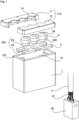
- FIG 1 shows a perspective exploded view of a cable bushing according to an embodiment of the invention with a Housing 1 with a cover 112, a counter-pressure plate 2 and several sealing elements 3 together with a suitable pre-assembled cable 4 with only a few reference numbers for the sake of clarity.
- the pre-assembled cable 4 includes a large number of strands 41, which are connected to a plug 40, and is for cable entry Fig. 1 suitable.
- a detailed description of the assembly of the cable gland with the cable 4 follows with reference to Figure 4a to d and Figure 5a to d and Figure 6a .
- the housing 1 includes an upper opening 10, which allows access to the interior of the housing 1 and is suitable for positioning the pre-assembled cable 4 with its plug 40 in the housing 1 in a simple manner as intended.
- the housing 1 also includes a cover 112 composed of two housing shells 11, 12 with a plurality of openings 14 for receiving a cable 4 and further cables 4 already positioned in the housing 1, a composite cover 112 placed on the opening 10 covering the opening 10 of the Housing 1 is closed.
- a support 102 for the counter-pressure plate 2 is provided near the opening 10.
- the counter-pressure plate 2 comprises a cable passage 234 with a cable inlet 24 and an opening 23, which allow a cable 4 that has already been positioned as intended in the housing 1 to be received.
- a sealing element 3 made of flexible and / or elastic material comprises an axial cable passage 34 with a slot 340, which starting from the cable passage 34 to a lateral edge of the sealing element 3.
- the sealing element 3 is designed to be suitable for receiving a cable 4 that has already been positioned as intended in the housing 1 by inserting it laterally through the slot 340 into its axial cable passage 34.
- a sealing element 3 arranged between the cover 112 and the counter-pressure plate 2 is also designed with a predetermined oversize compared to the cover 112 placed on the housing 1 and the counter-pressure plate 2 inserted into the housing 1, whereby it partially engages in a form-fitting manner in the opening 23 of the counter-pressure plate 2 and also a predetermined press and sealing connection between cable 4, sealing element 3, counter-pressure plate 2 and cover 112 is provided.
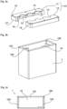
- Figure 2a shows the shell-shaped cover 112 of the housing 1 with its two housing shells 11 and 12, the parting plane of which runs centrally through the openings 14 for the cable 4 to pass through.
- the openings 14 of the cover 112 are conically expanded on the inside, starting from the edge of the openings 14 with the contour 13, in order to suitably cooperate with sealing elements 3, which will be described below with reference to Fig. 3a and b to be discribed.
- the cover 112 includes holes 15 suitable for screws.
- the sides of the two housing shells 11 and 12 corresponding to their parting plane are each designed as mutually corresponding contours 16, which interlock with each other in a form-fitting manner in such a way that the cover 112 is also sealed in the area of the parting plane.
- Cover 112 is made of a suitable plastic for this purpose.
- the cover 112 can include a further cord-like sealing element in the area of its parting plane.
- Figure 2b shows the housing 1 of Figure 1 with the opening 10 and a support 102 for the counter pressure plate 2
- Figure 2c shows a top view of the housing 1 of Figure 2b from above.
- the opening 10 has the edge 101 for placing the cover 112, which corresponds to the edge 111 of the cover 112.
- holes 105 are provided for fixing the cover 112 by means of screws, which correspond to the holes 15 in the cover 112.
- a support 102 suitable for the counter-pressure plate 2 is also provided in the housing 1 near the opening 10.
- the edition 102 of the execution of Figure 1 and 2 is designed for this purpose, for example, as two tiers, each of which extends over two opposite walls of the housing 1 and which partially continue on adjacent, also opposite walls.
- the edition 102 of the execution of Fig. 2b and c can also be designed as a projection which extends from the wall of the housing 1 by a predetermined amount into the interior of the housing 1, so that a stable positioning of the counter-pressure plate 2 on the support 102 is provided, and thereby also provides access to it Interior of the housing 1 is not affected by the opening 10 when inserting the pre-assembled cable 4.
- the edition 102 of the execution of Fig. 2b and c is particularly suitable for the one-piece counter-pressure plate 2 of the version Fig. 1 and 3c .
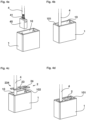
- Figure 3a shows an embodiment of a sealing element 3 from Figure 1 together with a sealing element 3 designed as a blind plug essentially include a first cylinder 31 with a first diameter on a second cylinder 32 with a second smaller diameter.
- the sealing element 3 includes the axial cable passage 34, from which the lateral slot 340 extends in the longitudinal direction through the first 31 and second 32 cylinders to the lateral edge of the sealing element 3.
- the elastic and/or flexible sealing element 3 can simply be opened radially to its axis via the slot 340, thereby exposing the cable passage 34 for the lateral insertion of the cable 4.
- the first cylinder 31 is designed to be rounded at the top in the vicinity of its opening 14 for suitable interaction with the cone 13 of the inner contour of the cover 112, which will also be described below with reference to Figure 6b and c is described.
- Figure 3b shows three sealing elements 3, which according to the embodiment of Figure 3a are designed and different than the individual sealing elements 3 of Figure 3a at the lower edge of the first cylinder 31 are connected to one another via a flat connection, for example a sealing element 3 can be designed as a blind plug.
- the connection of the sealing elements 3 only at the lower edge of their first cylinders 31 ensures that the sealing elements 3 are not impaired in their intended function by the connection.
- Figure 3c shows the counter pressure plate 2 of Figure 1 from above and Figure 3d a modification of the counter pressure plate 2 from Figure 3c , which are essentially two-dimensional with a predetermined thickness.
- the counter pressure plate 2 from Fig. 3c includes the cable outlets 234, each with a side cable inlet 24 and an opening 23, which allow a cable 4 that has already been positioned as intended in the housing 1 to be received.
- the extend Cable inlets 24 starting from the openings 23 each to a lateral edge of the counter-pressure plate 2, so that the openings 23 for the lateral insertion of a cable 4 are accessible via the cable inlets 24.
- the counter pressure plate 2 from Figure 3c is advantageously designed in one piece and is particularly suitable for the design of the housing 1 with the support 102 of Figure 2b and c.
- the counter pressure plate 2 from Figure 3d corresponds to the version of with its openings 23 Figure 3c , and is different from the counter pressure plate 2 of Figure 3c Like the cover 112, it is designed in two pieces and is composed of two essentially identical half-plates 20, 21, the parting plane of which runs centrally through the openings 23.
- the counter-pressure plate 2 has a cable passage 234 with a cable inlet 24 common to all openings 23, which is closed when its two half-plates 20, 21 are joined together.
- the counter pressure plate 2 from Figure 3d is for the design of the housing 1 with the support 102 of Figure 2b and c also suitable, whereby for a particularly stable and secure support, a correspondingly modified housing 1 can also include a closed support 102 that runs completely around its inner walls.
- the counter pressure plate 2 from Figure 3d is also particularly suitable for the design of the sealing elements 3 of Fig. 3b .
- the counter pressure plate 2 of the version Figure 3e comprises three individual plate elements 22, each provided with a cable passage 234, which essentially forms the counter-pressure plate 2 of Figure 3c corresponding counter pressure plate 2 can be assembled.
- the three plate elements 22 are essentially identical with their cable inlet 24 and their opening 23.
- the edges assigned to their respective adjacent plate elements 22 can suitably have contours that correspond to one another. This option is in Figure 3e each with dashed lines illustrated.
- the edges of the plate elements 22 can be designed, for example, in a dovetail-like or rail-like manner, so that a desirable cohesion of the plate elements 22 assembled to form the counter-pressure plate 2 is provided.
- a correspondingly modified housing 1 can also include a closed support 102 that runs completely around its inner walls.
- the sealing element 3 is under a press and sealing connection, the counter-pressure plate 2 being designed to be sufficiently stable to provide a counter-pressure on the sealing element 3, which also determines the material and the thickness of the counter-pressure plate 2.
- the counter-pressure plate 2 is suitably made of metal and the thickness of the counter-pressure plate 2 is of the design Figure 3d compared to the execution of Figure 3c increased in order to counteract pressure, particularly in the area of the parting plane of their half plates 20, 21.
- the area of the parting plane of the half-plates 20, 21 can also be designed to be stepped corresponding to one another, whereby the stability of a correspondingly assembled counter-pressure plate 2 is also increased in the area of the assembled gradations.
- the counter pressure plate 2 from Figure 3d can also be dimensioned in such a way that it rests directly on the edge 101 of the opening 10 of the housing 1, whereby the counter-pressure plate 2 can comprise a step, a contour or a profile on its edge, which is positively connected to the edge 101 of the housing 1 and /or the edge 111 of the Cover 112 corresponds. This possibility is indicated by the dashed line in Figure 3d indicated.
- further sealing measures can also be taken between the housing 1, the counter-pressure plate 2 and the cover 112 at their edges.
- such a counter-pressure plate 2 can also include suitable bores that correspond to the bores 15 and 105 of the cover 112 and the housing 1.
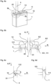
- Figures 4a to 4d show steps for assembling the cable gland Fig. 1 using the example of just a pre-assembled cable 4, where in Figure 1 the cable 4 is equipped with a plug 40 on its strands 41 and is inserted into the opening 10 of the housing 1 from above. In Figure 4b the plug 40 and the cable 4 are positioned at their predetermined position in the housing 1. The cable 4 protrudes from the housing 1.
- Figure 4c shows that outside the housing 1 via a cable inlet 24 of a cable passage 234 into an opening 23 of the counter-pressure plate 2 of Figure 1 and 3c inserted cable 4
- Figure 4d shows the counter-pressure plate 2 inserted as intended into the housing 1 on the support 102.
- the counter-pressure plate 2 is arranged near the opening 10 of the housing 1, and the edge 101 of the housing 1 protrudes upwards beyond the counter-pressure plate 2.
- the protruding edge 101 is desirable for the positioning of the counter-pressure plate 2 and for its interaction, in particular with the edge 111 of the cover 112.
- Figures 5a to 5d show further steps in assembling the cable gland Figure 1 following the steps of Figures 4a to 4d , where in Figure 5a , the cable 4 is inserted as intended via the slot 340 of a sealing element 3 into its axial cable passage 34.
- the other similar sealing elements 3 are designed as blind plugs without cable passage 34 and slot 340 to provide a suitable seal.
- the housing shells 11 and 12 are suitably positioned relative to the cable 4 so that they face the cover 112 of Figure 5d can be assembled, their contours 16 interlocking and the cable 4 being arranged in an opening 14 with its inside conical contour 13.
- the cover 112 is placed under pressure with its edge 111 onto the edge 101 of the opening 10 of the housing 1, with a pressing pressure P being exerted on the first cylinders 31 of the elastic and/or flexible sealing elements 3, which are designed with a predetermined oversize, and to them corresponding compression and development of its sealing effect.
- the cover 112 is fixed to the housing 1 by means of suitable screws (not shown) through the holes 15 and 105 of the cover 112 and housing 1, after which the fully assembled cable bushing of Figure 6a is provided.
- Figure 6b shows the above description of the installation of the cable gland with reference Figure 5d and 6a an enlarged view of section A1 of a longitudinal section through the line SL-SL of Figure 6a centrally along the axis of the cable 4, and Figure 6c shows an enlarged view of section A2 of Figure 6b .
- Figure 6d shows an enlarged view of section A3 of Fig. 6b with a modified design of the edge 101 of the housing 1, on which the edge 111 of the cover 112 rests, which is suitable for providing a further desirable seal of the housing 1, the edge 101 and the edge 111 each having corresponding, positively interlocking contours.
- a suitable sealing ring can also be provided in addition to or as an alternative to the above contour.
Landscapes
- Engineering & Computer Science (AREA)
- Architecture (AREA)
- Civil Engineering (AREA)
- Structural Engineering (AREA)
- Microelectronics & Electronic Packaging (AREA)
- Installation Of Indoor Wiring (AREA)
- Cable Accessories (AREA)
Claims (12)
- Traversée de câble pour au moins un câble (4) dans un boîtier (1) doté d'une ouverture (10), qui est pourvue d'un couvercle (112) comprenant au moins deux coques de boîtier (11, 12) et doté d'au moins une ouverture (14), un plan de séparation des coques de boîtier (11, 12) s'étendant centralement à travers l'ouverture (14) ; et au moins un élément d'étanchéité (3) élastique et/ou souple étant prévu pour réaliser l'étanchéité du boîtier (1), lequel élément d'étanchéité comprend un passage de câble (34) doté d'une fente (340) vers son bord latéral, une plaque de contre-pression (2) comprenant au moins un passage de câble (234) et recouvrant l'ouverture (10) étant prévue, laquelle coopère avec l'élément d'étanchéité (3) et le couvercle (112) pour réaliser l'étanchéité du boîtier (1), l'élément d'étanchéité (3) étant disposé avec une surdimension prédéfinie entre le couvercle (112) et la plaque de contre-pression (2) et étant soumis à une pression axiale (P), l'élément d'étanchéité (3) présentant un premier cylindre (31) qui repose sur la plaque de contre-pression (2) et est arrondi dans l'environnement de l'ouverture (14) du couvercle (112), et l'ouverture (14) du couvercle (112) s'élargissant en forme de cône du côté intérieur à partir d'un bord de l'ouverture (14), de sorte qu'un contour (13) soit produit, lequel coopère avec l'arrondi de l'élément d'étanchéité (3) de telle sorte que l'élément d'étanchéité (3) soumis à la pression (P) subit une compression (K) axiale (A) et radiale (R) sans qu'aucune force de cisaillement ne survienne.
- Traversée de câble selon la revendication 1,
caractérisée en ce que
le passage de câble (234) de la plaque de contre-pression (2) comprend au moins une ouverture traversante (23) et au moins une entrée de câble (24) latérale pour l'insertion latérale du câble (4) dans l'ouverture (23). - Traversée de câble selon la revendication 1 ou 2,
caractérisée en ce
qu'un support (102) sur lequel la plaque de contre-pression (2) repose est formé dans l'environnement de l'ouverture (10) du côté intérieur sur une paroi du boîtier (1). - Traversée de câble selon l'une des revendications précédentes 1 à 3,
caractérisée en ce que
la plaque de contre-pression (2) est formée d'une seule pièce. - Traversée de câble selon l'une des revendications précédentes 1 à 3,
caractérisée en ce que
la plaque de contre-pression (2) est formée en deux pièces et se compose de deux demi-plaques (20, 21) formées de manière sensiblement identique, plaques dont le plan de séparation s'étend centralement à travers l'ouverture (23) de la plaque de contre-pression (2). - Traversée de câble selon l'une des revendications précédentes 1 à 3,
caractérisée en ce que
la plaque de contre-pression (2) se compose d'une pluralité d'éléments de plaques (22) individuels dotés respectivement d'au moins un passage de câble (234). - Traversée de câble selon l'une des revendications précédentes 1 à 6,
caractérisée en ce que
les côtés des deux coques de boîtier (11, 12) correspondant au plan de séparation des coques de boîtier (11, 12) sont formés respectivement en tant que contours (16) correspondant les uns aux autres, lesquels viennent en prise avec complémentarité de formes les uns dans les autres de telle sorte que le couvercle (112) est rendu étanche également dans la région du plan de séparation. - Traversée de câble selon l'une des revendications précédentes 1 à 7,
caractérisée en ce que
l'élément d'étanchéité (3) comprend le premier cylindre (31) doté d'un premier diamètre et un deuxième cylindre (32) doté d'un deuxième diamètre plus petit, le passage de câble (34) étant formé axialement à travers le premier (31) et le deuxième (32) cylindre, et la fente (340) s'étendant dans la direction longitudinale à travers le premier (31) et le deuxième (32) cylindre jusqu'à un bord latéral de l'élément d'étanchéité (3). - Traversée de câble selon la revendication 8,
caractérisée en ce que
le deuxième cylindre (32) est disposé dans l'ouverture (23) avec complémentarité de formes avec l'ouverture (23) de la plaque de contre-pression (2). - Traversée de câble selon l'une des revendications précédentes 1 à 9,
caractérisée en ce que
le câble (4) est un câble électrique (4) préfabriqué qui peut être pourvu d'un connecteur (40). - Traversée de câble selon l'une des revendications précédentes 1 à 10,
caractérisée en ce quele boîtier (1) est formé à partir de matière synthétique et/ou de métal et le couvercle (112) est formé à partir de matière synthétique, et la plaque de contre-pression (2) est formée à partir de matière synthétique et de préférence à partir de métal présentant une épaisseur (épaisseur) prédéfinie, etl'élément d'étanchéité (3) est formé d'une seule pièce à partir d'une matière d'étanchéité souple et/ou élastique appropriée. - Traversée de câble selon l'une des revendications précédentes 1 à 11, l'élément d'étanchéité (3) étant formé en tant que plot de remplissage sans le passage de câble (34) et la fente (340).
Applications Claiming Priority (3)
| Application Number | Priority Date | Filing Date | Title |
|---|---|---|---|
| DE102017127774 | 2017-11-24 | ||
| DE102017129923.8A DE102017129923A1 (de) | 2017-11-24 | 2017-12-14 | Kabeldurchführung |
| PCT/DE2018/100930 WO2019101268A1 (fr) | 2017-11-24 | 2018-11-14 | Traversée de câble |
Publications (2)
| Publication Number | Publication Date |
|---|---|
| EP3714520A1 EP3714520A1 (fr) | 2020-09-30 |
| EP3714520B1 true EP3714520B1 (fr) | 2024-02-21 |
Family
ID=66442086
Family Applications (1)
| Application Number | Title | Priority Date | Filing Date |
|---|---|---|---|
| EP18815508.9A Active EP3714520B1 (fr) | 2017-11-24 | 2018-11-14 | Traversée de câble |
Country Status (5)
| Country | Link |
|---|---|
| US (1) | US11038333B2 (fr) |
| EP (1) | EP3714520B1 (fr) |
| CN (1) | CN111373618B (fr) |
| DE (1) | DE102017129923A1 (fr) |
| WO (1) | WO2019101268A1 (fr) |
Families Citing this family (11)
| Publication number | Priority date | Publication date | Assignee | Title |
|---|---|---|---|---|
| GB2607454B (en) * | 2020-03-17 | 2025-02-19 | Mitsubishi Electric Corp | Circuit box |
| US11505953B1 (en) * | 2020-04-30 | 2022-11-22 | Concrete Voids LLC | Concrete beam conduit guide |
| US11510331B2 (en) * | 2020-09-10 | 2022-11-22 | Dell Products, L.P. | Profile-modeling cable clip for sealing airflow in an information handling system (IHS) chassis |
| GB2600950A (en) * | 2020-11-12 | 2022-05-18 | Continental Automotive Gmbh | Electronic assembly and method of producing the same |
| CN112706632A (zh) * | 2020-12-23 | 2021-04-27 | 中车永济电机有限公司 | 充电机柜体的密封结构 |
| US20220224097A1 (en) * | 2021-01-14 | 2022-07-14 | Quanta Computer Inc. | Cable-entry device for an electronic chassis |
| US12126152B2 (en) * | 2021-04-29 | 2024-10-22 | APG Vision LLC | Ball mount with integrated cable gland |
| CN113328358A (zh) * | 2021-05-18 | 2021-08-31 | 中国建筑第八工程局有限公司 | 配电箱和桥架连接处的封堵装置及其使用方法 |
| DE102021122931A1 (de) * | 2021-09-06 | 2023-03-09 | Endress+Hauser Flowtec Ag | Elektrische Durchführung und Elektronikgehäuse |
| EP4160292A1 (fr) * | 2021-09-30 | 2023-04-05 | Corning Research & Development Corporation | Système d'étanchéité pour fermetures de télécommunication |
| FR3129040B1 (fr) * | 2021-11-10 | 2024-05-31 | Speedinnov | Armoire électrique, notamment pour un véhicule ferroviaire |
Citations (5)
| Publication number | Priority date | Publication date | Assignee | Title |
|---|---|---|---|---|
| JPS57161282U (fr) * | 1981-04-02 | 1982-10-09 | ||
| DE19723032C1 (de) * | 1997-06-02 | 1998-10-01 | Harting Kgaa | Abgedichtete Kabeleinführung |
| EP0901190A2 (fr) * | 1997-09-06 | 1999-03-10 | Rose-Elektrotechnik GmbH + Co KG Elektrotechnische Fabrik | Système de traversée câble-fiche |
| DE29911305U1 (de) * | 1999-06-29 | 1999-11-04 | Rose-Elektrotechnik Gmbh & Co Kg Elektrotechnische Fabrik, 32457 Porta Westfalica | Kabel-Stecker-Durchführsystem |
| DE102010046857B3 (de) * | 2010-09-29 | 2011-12-15 | Adc Gmbh | Kabeldurchführung und Verfahren zur Durchführung eines Kabels durch eine Öffnung in einer Wand- oder Bodenplatte |
Family Cites Families (18)
| Publication number | Priority date | Publication date | Assignee | Title |
|---|---|---|---|---|
| DE20217273U1 (de) * | 2002-11-09 | 2003-01-16 | HARTING Electric GmbH & Co. KG, 32339 Espelkamp | Befestigungsvorrichtung für Steckverbinder |
| DE10350433A1 (de) * | 2003-10-29 | 2005-07-07 | Krone Gmbh | Wandauslassdose |
| DE102006062609A1 (de) | 2005-07-28 | 2008-07-03 | Hidde, Axel R., Dr. | Kabeldurch-/-einführungselement zum Dichten, Klemmen, Schirmen und Leiten |
| DE202005020026U1 (de) * | 2005-12-22 | 2006-03-16 | Harting Electric Gmbh & Co. Kg | Halterahmen für Steckermodule |
| JP2008028267A (ja) * | 2006-07-24 | 2008-02-07 | Fanuc Ltd | 電気回路ユニットのシール構造 |
| US7411128B2 (en) * | 2006-09-26 | 2008-08-12 | Lapp Engineering & Co. | Cable feed-through and cable feed-through system |
| DE102008022908B4 (de) * | 2008-05-09 | 2014-11-27 | Yamaichi Electronics Deutschland Gmbh | Anschlußdose, Verwendungen einer Anschlußdose und Verfahren |
| DE102011103351B3 (de) * | 2011-05-27 | 2012-09-13 | Phoenix Contact Gmbh & Co. Kg | Dichtungselement und Anschlussgehäuse mit einem Dichtungselement |
| DE202012101639U1 (de) | 2012-05-03 | 2013-08-06 | Weidmüller Interface GmbH & Co. KG | Durchführungsgehäuse |
| US9121244B2 (en) * | 2012-06-14 | 2015-09-01 | Schlumberger Technology Corporation | Elastically responsive unibody shear valve |
| JP6272887B2 (ja) * | 2012-10-24 | 2018-01-31 | ポール スミス デイビッド | 大きな流量容量のために流体力制御を行う電気油圧式の圧力低減及び解放バルブ |
| DE102014003038B4 (de) * | 2014-03-07 | 2021-09-30 | Murrplastik Systemtechnik Gmbh | Leitungsdurchführung |
| US9494761B2 (en) * | 2014-07-31 | 2016-11-15 | All Systems Broadband, Inc. | Bracket for securing multiple fiber optic cables to a termination box |
| DE102015114697B4 (de) * | 2015-09-03 | 2020-03-26 | Harting Electric Gmbh & Co. Kg | Halterahmen für Steckverbindermodule |
| DE102015114702B4 (de) * | 2015-09-03 | 2019-01-31 | Harting Electric Gmbh & Co. Kg | Halterahmen |
| DE102016114577A1 (de) * | 2016-08-05 | 2018-02-08 | Harting Electric Gmbh & Co. Kg | Vorrichtung und Verfahren zur Kabeldurchführung durch einen Wanddurchbruch |
| WO2018053132A1 (fr) * | 2016-09-15 | 2018-03-22 | Proserv Operations, Inc. | Composants de commande de circuit hydraulique à faible frottement |
| DE102018101790A1 (de) * | 2018-01-26 | 2019-08-01 | Harting Electric Gmbh & Co. Kg | Dichteinsatz |
-
2017
- 2017-12-14 DE DE102017129923.8A patent/DE102017129923A1/de not_active Withdrawn
-
2018
- 2018-11-14 US US16/762,103 patent/US11038333B2/en active Active
- 2018-11-14 CN CN201880075346.4A patent/CN111373618B/zh active Active
- 2018-11-14 EP EP18815508.9A patent/EP3714520B1/fr active Active
- 2018-11-14 WO PCT/DE2018/100930 patent/WO2019101268A1/fr not_active Ceased
Patent Citations (5)
| Publication number | Priority date | Publication date | Assignee | Title |
|---|---|---|---|---|
| JPS57161282U (fr) * | 1981-04-02 | 1982-10-09 | ||
| DE19723032C1 (de) * | 1997-06-02 | 1998-10-01 | Harting Kgaa | Abgedichtete Kabeleinführung |
| EP0901190A2 (fr) * | 1997-09-06 | 1999-03-10 | Rose-Elektrotechnik GmbH + Co KG Elektrotechnische Fabrik | Système de traversée câble-fiche |
| DE29911305U1 (de) * | 1999-06-29 | 1999-11-04 | Rose-Elektrotechnik Gmbh & Co Kg Elektrotechnische Fabrik, 32457 Porta Westfalica | Kabel-Stecker-Durchführsystem |
| DE102010046857B3 (de) * | 2010-09-29 | 2011-12-15 | Adc Gmbh | Kabeldurchführung und Verfahren zur Durchführung eines Kabels durch eine Öffnung in einer Wand- oder Bodenplatte |
Also Published As
| Publication number | Publication date |
|---|---|
| EP3714520A1 (fr) | 2020-09-30 |
| CN111373618A (zh) | 2020-07-03 |
| DE102017129923A1 (de) | 2019-05-29 |
| US11038333B2 (en) | 2021-06-15 |
| US20200358276A1 (en) | 2020-11-12 |
| WO2019101268A1 (fr) | 2019-05-31 |
| CN111373618B (zh) | 2021-12-10 |
Similar Documents
| Publication | Publication Date | Title |
|---|---|---|
| EP3714520B1 (fr) | Traversée de câble | |
| DE10244408B4 (de) | Durchgangstülle mit Kunststoffeinsatz | |
| EP1606867B1 (fr) | Dispositif de traversee de cable | |
| EP2764591B1 (fr) | Traversée de câbles et procédé de montage d'une traversée de câbles | |
| DE102006016882B4 (de) | Steckverbinder | |
| EP3517816B1 (fr) | Connecteur avec boîtier | |
| EP3494621B1 (fr) | Dispositif et procédé de passage de câbles à travers une ouverture de mur | |
| EP3652831B1 (fr) | Passe-câble à décharge de traction | |
| DE102017208477A1 (de) | Kabeldurchführung | |
| EP3566274B1 (fr) | Entrée de câble | |
| WO2021170175A1 (fr) | Dispositif d'entrée de câble pour armoire de commande, son agencement et son procédé de fonctionnement | |
| EP2034562B1 (fr) | Connecteur à fiches doté d'un corps d'isolation en une pièce | |
| EP2024979B1 (fr) | Dispositif pour absorber le bruit | |
| EP1595318B1 (fr) | Passage de cables | |
| EP0844694A2 (fr) | Dispositif de serrage | |
| EP3963163B1 (fr) | Dispositif de bouchon | |
| DE102023125550B3 (de) | Einschubdichtung für ein Installationsgehäuse | |
| DE102010046857B3 (de) | Kabeldurchführung und Verfahren zur Durchführung eines Kabels durch eine Öffnung in einer Wand- oder Bodenplatte | |
| EP4591404A1 (fr) | Élément de contact électrique, insert de connecteur enfichable et connecteur enfichable industriel modulaire le comprenant | |
| EP0550839B1 (fr) | Boîte de jonction en forme de caisson pour câble électronique | |
| EP1480309B1 (fr) | Bouchon de fermeture d'une ouverture prévue pour le passage de câbles | |
| DE19723032C1 (de) | Abgedichtete Kabeleinführung | |
| DE8337725U1 (de) | Stecker für Schwachstromgeräte | |
| DE3412347A1 (de) | Schutzkontaktstecker in wasserdichter ausfuehrung | |
| DE102010018596B4 (de) | Kabeldurchführung |
Legal Events
| Date | Code | Title | Description |
|---|---|---|---|
| STAA | Information on the status of an ep patent application or granted ep patent |
Free format text: STATUS: UNKNOWN |
|
| STAA | Information on the status of an ep patent application or granted ep patent |
Free format text: STATUS: THE INTERNATIONAL PUBLICATION HAS BEEN MADE |
|
| PUAI | Public reference made under article 153(3) epc to a published international application that has entered the european phase |
Free format text: ORIGINAL CODE: 0009012 |
|
| STAA | Information on the status of an ep patent application or granted ep patent |
Free format text: STATUS: REQUEST FOR EXAMINATION WAS MADE |
|
| 17P | Request for examination filed |
Effective date: 20200522 |
|
| AK | Designated contracting states |
Kind code of ref document: A1 Designated state(s): AL AT BE BG CH CY CZ DE DK EE ES FI FR GB GR HR HU IE IS IT LI LT LU LV MC MK MT NL NO PL PT RO RS SE SI SK SM TR |
|
| AX | Request for extension of the european patent |
Extension state: BA ME |
|
| DAV | Request for validation of the european patent (deleted) | ||
| DAX | Request for extension of the european patent (deleted) | ||
| STAA | Information on the status of an ep patent application or granted ep patent |
Free format text: STATUS: EXAMINATION IS IN PROGRESS |
|
| 17Q | First examination report despatched |
Effective date: 20220214 |
|
| P01 | Opt-out of the competence of the unified patent court (upc) registered |
Effective date: 20230603 |
|
| GRAP | Despatch of communication of intention to grant a patent |
Free format text: ORIGINAL CODE: EPIDOSNIGR1 |
|
| STAA | Information on the status of an ep patent application or granted ep patent |
Free format text: STATUS: GRANT OF PATENT IS INTENDED |
|
| INTG | Intention to grant announced |
Effective date: 20230911 |
|
| GRAS | Grant fee paid |
Free format text: ORIGINAL CODE: EPIDOSNIGR3 |
|
| GRAA | (expected) grant |
Free format text: ORIGINAL CODE: 0009210 |
|
| STAA | Information on the status of an ep patent application or granted ep patent |
Free format text: STATUS: THE PATENT HAS BEEN GRANTED |
|
| AK | Designated contracting states |
Kind code of ref document: B1 Designated state(s): AL AT BE BG CH CY CZ DE DK EE ES FI FR GB GR HR HU IE IS IT LI LT LU LV MC MK MT NL NO PL PT RO RS SE SI SK SM TR |
|
| RAP3 | Party data changed (applicant data changed or rights of an application transferred) |
Owner name: HARTING ELECTRIC STIFTUNG & CO. KG |
|
| REG | Reference to a national code |
Ref country code: GB Ref legal event code: FG4D Free format text: NOT ENGLISH |
|
| REG | Reference to a national code |
Ref country code: CH Ref legal event code: EP |
|
| REG | Reference to a national code |
Ref country code: DE Ref legal event code: R096 Ref document number: 502018014153 Country of ref document: DE |
|
| REG | Reference to a national code |
Ref country code: IE Ref legal event code: FG4D Free format text: LANGUAGE OF EP DOCUMENT: GERMAN |
|
| REG | Reference to a national code |
Ref country code: LT Ref legal event code: MG9D |
|
| REG | Reference to a national code |
Ref country code: NL Ref legal event code: MP Effective date: 20240221 |
|
| PG25 | Lapsed in a contracting state [announced via postgrant information from national office to epo] |
Ref country code: IS Free format text: LAPSE BECAUSE OF FAILURE TO SUBMIT A TRANSLATION OF THE DESCRIPTION OR TO PAY THE FEE WITHIN THE PRESCRIBED TIME-LIMIT Effective date: 20240621 |
|
| PG25 | Lapsed in a contracting state [announced via postgrant information from national office to epo] |
Ref country code: LT Free format text: LAPSE BECAUSE OF FAILURE TO SUBMIT A TRANSLATION OF THE DESCRIPTION OR TO PAY THE FEE WITHIN THE PRESCRIBED TIME-LIMIT Effective date: 20240221 |
|
| PG25 | Lapsed in a contracting state [announced via postgrant information from national office to epo] |
Ref country code: GR Free format text: LAPSE BECAUSE OF FAILURE TO SUBMIT A TRANSLATION OF THE DESCRIPTION OR TO PAY THE FEE WITHIN THE PRESCRIBED TIME-LIMIT Effective date: 20240522 |
|
| PG25 | Lapsed in a contracting state [announced via postgrant information from national office to epo] |
Ref country code: HR Free format text: LAPSE BECAUSE OF FAILURE TO SUBMIT A TRANSLATION OF THE DESCRIPTION OR TO PAY THE FEE WITHIN THE PRESCRIBED TIME-LIMIT Effective date: 20240221 Ref country code: RS Free format text: LAPSE BECAUSE OF FAILURE TO SUBMIT A TRANSLATION OF THE DESCRIPTION OR TO PAY THE FEE WITHIN THE PRESCRIBED TIME-LIMIT Effective date: 20240521 Ref country code: NL Free format text: LAPSE BECAUSE OF FAILURE TO SUBMIT A TRANSLATION OF THE DESCRIPTION OR TO PAY THE FEE WITHIN THE PRESCRIBED TIME-LIMIT Effective date: 20240221 |
|
| PG25 | Lapsed in a contracting state [announced via postgrant information from national office to epo] |
Ref country code: ES Free format text: LAPSE BECAUSE OF FAILURE TO SUBMIT A TRANSLATION OF THE DESCRIPTION OR TO PAY THE FEE WITHIN THE PRESCRIBED TIME-LIMIT Effective date: 20240221 |
|
| PG25 | Lapsed in a contracting state [announced via postgrant information from national office to epo] |
Ref country code: RS Free format text: LAPSE BECAUSE OF FAILURE TO SUBMIT A TRANSLATION OF THE DESCRIPTION OR TO PAY THE FEE WITHIN THE PRESCRIBED TIME-LIMIT Effective date: 20240521 Ref country code: NO Free format text: LAPSE BECAUSE OF FAILURE TO SUBMIT A TRANSLATION OF THE DESCRIPTION OR TO PAY THE FEE WITHIN THE PRESCRIBED TIME-LIMIT Effective date: 20240521 Ref country code: NL Free format text: LAPSE BECAUSE OF FAILURE TO SUBMIT A TRANSLATION OF THE DESCRIPTION OR TO PAY THE FEE WITHIN THE PRESCRIBED TIME-LIMIT Effective date: 20240221 Ref country code: LT Free format text: LAPSE BECAUSE OF FAILURE TO SUBMIT A TRANSLATION OF THE DESCRIPTION OR TO PAY THE FEE WITHIN THE PRESCRIBED TIME-LIMIT Effective date: 20240221 Ref country code: IS Free format text: LAPSE BECAUSE OF FAILURE TO SUBMIT A TRANSLATION OF THE DESCRIPTION OR TO PAY THE FEE WITHIN THE PRESCRIBED TIME-LIMIT Effective date: 20240621 Ref country code: HR Free format text: LAPSE BECAUSE OF FAILURE TO SUBMIT A TRANSLATION OF THE DESCRIPTION OR TO PAY THE FEE WITHIN THE PRESCRIBED TIME-LIMIT Effective date: 20240221 Ref country code: GR Free format text: LAPSE BECAUSE OF FAILURE TO SUBMIT A TRANSLATION OF THE DESCRIPTION OR TO PAY THE FEE WITHIN THE PRESCRIBED TIME-LIMIT Effective date: 20240522 Ref country code: FI Free format text: LAPSE BECAUSE OF FAILURE TO SUBMIT A TRANSLATION OF THE DESCRIPTION OR TO PAY THE FEE WITHIN THE PRESCRIBED TIME-LIMIT Effective date: 20240221 Ref country code: ES Free format text: LAPSE BECAUSE OF FAILURE TO SUBMIT A TRANSLATION OF THE DESCRIPTION OR TO PAY THE FEE WITHIN THE PRESCRIBED TIME-LIMIT Effective date: 20240221 Ref country code: BG Free format text: LAPSE BECAUSE OF FAILURE TO SUBMIT A TRANSLATION OF THE DESCRIPTION OR TO PAY THE FEE WITHIN THE PRESCRIBED TIME-LIMIT Effective date: 20240221 |
|
| PG25 | Lapsed in a contracting state [announced via postgrant information from national office to epo] |
Ref country code: PL Free format text: LAPSE BECAUSE OF FAILURE TO SUBMIT A TRANSLATION OF THE DESCRIPTION OR TO PAY THE FEE WITHIN THE PRESCRIBED TIME-LIMIT Effective date: 20240221 Ref country code: PT Free format text: LAPSE BECAUSE OF FAILURE TO SUBMIT A TRANSLATION OF THE DESCRIPTION OR TO PAY THE FEE WITHIN THE PRESCRIBED TIME-LIMIT Effective date: 20240621 |
|
| PG25 | Lapsed in a contracting state [announced via postgrant information from national office to epo] |
Ref country code: SE Free format text: LAPSE BECAUSE OF FAILURE TO SUBMIT A TRANSLATION OF THE DESCRIPTION OR TO PAY THE FEE WITHIN THE PRESCRIBED TIME-LIMIT Effective date: 20240221 Ref country code: PT Free format text: LAPSE BECAUSE OF FAILURE TO SUBMIT A TRANSLATION OF THE DESCRIPTION OR TO PAY THE FEE WITHIN THE PRESCRIBED TIME-LIMIT Effective date: 20240621 Ref country code: PL Free format text: LAPSE BECAUSE OF FAILURE TO SUBMIT A TRANSLATION OF THE DESCRIPTION OR TO PAY THE FEE WITHIN THE PRESCRIBED TIME-LIMIT Effective date: 20240221 Ref country code: LV Free format text: LAPSE BECAUSE OF FAILURE TO SUBMIT A TRANSLATION OF THE DESCRIPTION OR TO PAY THE FEE WITHIN THE PRESCRIBED TIME-LIMIT Effective date: 20240221 |
|
| PG25 | Lapsed in a contracting state [announced via postgrant information from national office to epo] |
Ref country code: DK Free format text: LAPSE BECAUSE OF FAILURE TO SUBMIT A TRANSLATION OF THE DESCRIPTION OR TO PAY THE FEE WITHIN THE PRESCRIBED TIME-LIMIT Effective date: 20240221 |
|
| PG25 | Lapsed in a contracting state [announced via postgrant information from national office to epo] |
Ref country code: SM Free format text: LAPSE BECAUSE OF FAILURE TO SUBMIT A TRANSLATION OF THE DESCRIPTION OR TO PAY THE FEE WITHIN THE PRESCRIBED TIME-LIMIT Effective date: 20240221 |
|
| PG25 | Lapsed in a contracting state [announced via postgrant information from national office to epo] |
Ref country code: CZ Free format text: LAPSE BECAUSE OF FAILURE TO SUBMIT A TRANSLATION OF THE DESCRIPTION OR TO PAY THE FEE WITHIN THE PRESCRIBED TIME-LIMIT Effective date: 20240221 Ref country code: EE Free format text: LAPSE BECAUSE OF FAILURE TO SUBMIT A TRANSLATION OF THE DESCRIPTION OR TO PAY THE FEE WITHIN THE PRESCRIBED TIME-LIMIT Effective date: 20240221 |
|
| PG25 | Lapsed in a contracting state [announced via postgrant information from national office to epo] |
Ref country code: SK Free format text: LAPSE BECAUSE OF FAILURE TO SUBMIT A TRANSLATION OF THE DESCRIPTION OR TO PAY THE FEE WITHIN THE PRESCRIBED TIME-LIMIT Effective date: 20240221 |
|
| PG25 | Lapsed in a contracting state [announced via postgrant information from national office to epo] |
Ref country code: SM Free format text: LAPSE BECAUSE OF FAILURE TO SUBMIT A TRANSLATION OF THE DESCRIPTION OR TO PAY THE FEE WITHIN THE PRESCRIBED TIME-LIMIT Effective date: 20240221 Ref country code: SK Free format text: LAPSE BECAUSE OF FAILURE TO SUBMIT A TRANSLATION OF THE DESCRIPTION OR TO PAY THE FEE WITHIN THE PRESCRIBED TIME-LIMIT Effective date: 20240221 Ref country code: RO Free format text: LAPSE BECAUSE OF FAILURE TO SUBMIT A TRANSLATION OF THE DESCRIPTION OR TO PAY THE FEE WITHIN THE PRESCRIBED TIME-LIMIT Effective date: 20240221 Ref country code: EE Free format text: LAPSE BECAUSE OF FAILURE TO SUBMIT A TRANSLATION OF THE DESCRIPTION OR TO PAY THE FEE WITHIN THE PRESCRIBED TIME-LIMIT Effective date: 20240221 Ref country code: DK Free format text: LAPSE BECAUSE OF FAILURE TO SUBMIT A TRANSLATION OF THE DESCRIPTION OR TO PAY THE FEE WITHIN THE PRESCRIBED TIME-LIMIT Effective date: 20240221 Ref country code: CZ Free format text: LAPSE BECAUSE OF FAILURE TO SUBMIT A TRANSLATION OF THE DESCRIPTION OR TO PAY THE FEE WITHIN THE PRESCRIBED TIME-LIMIT Effective date: 20240221 |
|
| REG | Reference to a national code |
Ref country code: DE Ref legal event code: R097 Ref document number: 502018014153 Country of ref document: DE |
|
| PG25 | Lapsed in a contracting state [announced via postgrant information from national office to epo] |
Ref country code: IT Free format text: LAPSE BECAUSE OF FAILURE TO SUBMIT A TRANSLATION OF THE DESCRIPTION OR TO PAY THE FEE WITHIN THE PRESCRIBED TIME-LIMIT Effective date: 20240221 |
|
| PLBE | No opposition filed within time limit |
Free format text: ORIGINAL CODE: 0009261 |
|
| STAA | Information on the status of an ep patent application or granted ep patent |
Free format text: STATUS: NO OPPOSITION FILED WITHIN TIME LIMIT |
|
| PG25 | Lapsed in a contracting state [announced via postgrant information from national office to epo] |
Ref country code: IT Free format text: LAPSE BECAUSE OF FAILURE TO SUBMIT A TRANSLATION OF THE DESCRIPTION OR TO PAY THE FEE WITHIN THE PRESCRIBED TIME-LIMIT Effective date: 20240221 |
|
| 26N | No opposition filed |
Effective date: 20241122 |
|
| PG25 | Lapsed in a contracting state [announced via postgrant information from national office to epo] |
Ref country code: SI Free format text: LAPSE BECAUSE OF FAILURE TO SUBMIT A TRANSLATION OF THE DESCRIPTION OR TO PAY THE FEE WITHIN THE PRESCRIBED TIME-LIMIT Effective date: 20240221 |
|
| REG | Reference to a national code |
Ref country code: CH Ref legal event code: PL |
|
| PG25 | Lapsed in a contracting state [announced via postgrant information from national office to epo] |
Ref country code: MC Free format text: LAPSE BECAUSE OF FAILURE TO SUBMIT A TRANSLATION OF THE DESCRIPTION OR TO PAY THE FEE WITHIN THE PRESCRIBED TIME-LIMIT Effective date: 20240221 |
|
| PG25 | Lapsed in a contracting state [announced via postgrant information from national office to epo] |
Ref country code: LU Free format text: LAPSE BECAUSE OF NON-PAYMENT OF DUE FEES Effective date: 20241114 |
|
| REG | Reference to a national code |
Ref country code: CH Ref legal event code: PL |
|
| PG25 | Lapsed in a contracting state [announced via postgrant information from national office to epo] |
Ref country code: CH Free format text: LAPSE BECAUSE OF NON-PAYMENT OF DUE FEES Effective date: 20241130 |
|
| REG | Reference to a national code |
Ref country code: BE Ref legal event code: MM Effective date: 20241130 |
|
| PG25 | Lapsed in a contracting state [announced via postgrant information from national office to epo] |
Ref country code: BE Free format text: LAPSE BECAUSE OF NON-PAYMENT OF DUE FEES Effective date: 20241130 |
|
| PG25 | Lapsed in a contracting state [announced via postgrant information from national office to epo] |
Ref country code: IE Free format text: LAPSE BECAUSE OF NON-PAYMENT OF DUE FEES Effective date: 20241114 |
|
| PGFP | Annual fee paid to national office [announced via postgrant information from national office to epo] |
Ref country code: DE Payment date: 20251126 Year of fee payment: 8 |
|
| PGFP | Annual fee paid to national office [announced via postgrant information from national office to epo] |
Ref country code: GB Payment date: 20251125 Year of fee payment: 8 |
|
| PG25 | Lapsed in a contracting state [announced via postgrant information from national office to epo] |
Ref country code: AT Free format text: LAPSE BECAUSE OF NON-PAYMENT OF DUE FEES Effective date: 20241114 |
|
| PGFP | Annual fee paid to national office [announced via postgrant information from national office to epo] |
Ref country code: FR Payment date: 20251124 Year of fee payment: 8 |
|
| REG | Reference to a national code |
Ref country code: AT Ref legal event code: MM01 Ref document number: 1659954 Country of ref document: AT Kind code of ref document: T Effective date: 20241114 |
|
| PG25 | Lapsed in a contracting state [announced via postgrant information from national office to epo] |
Ref country code: HU Free format text: LAPSE BECAUSE OF FAILURE TO SUBMIT A TRANSLATION OF THE DESCRIPTION OR TO PAY THE FEE WITHIN THE PRESCRIBED TIME-LIMIT; INVALID AB INITIO Effective date: 20181114 |
|
| PG25 | Lapsed in a contracting state [announced via postgrant information from national office to epo] |
Ref country code: CY Free format text: LAPSE BECAUSE OF FAILURE TO SUBMIT A TRANSLATION OF THE DESCRIPTION OR TO PAY THE FEE WITHIN THE PRESCRIBED TIME-LIMIT; INVALID AB INITIO Effective date: 20181114 |