EP3714601B1 - Rendu de trame de référence basée sur un champ de mouvement pour une prédiction à compensation de mouvement en codage vidéo - Google Patents
Rendu de trame de référence basée sur un champ de mouvement pour une prédiction à compensation de mouvement en codage vidéo Download PDFInfo
- Publication number
- EP3714601B1 EP3714601B1 EP18769923.6A EP18769923A EP3714601B1 EP 3714601 B1 EP3714601 B1 EP 3714601B1 EP 18769923 A EP18769923 A EP 18769923A EP 3714601 B1 EP3714601 B1 EP 3714601B1
- Authority
- EP
- European Patent Office
- Prior art keywords
- frame
- block
- reference frame
- motion field
- motion
- Prior art date
- Legal status (The legal status is an assumption and is not a legal conclusion. Google has not performed a legal analysis and makes no representation as to the accuracy of the status listed.)
- Active
Links
Images




Classifications
-
- H—ELECTRICITY
- H04—ELECTRIC COMMUNICATION TECHNIQUE
- H04N—PICTORIAL COMMUNICATION, e.g. TELEVISION
- H04N19/00—Methods or arrangements for coding, decoding, compressing or decompressing digital video signals
- H04N19/50—Methods or arrangements for coding, decoding, compressing or decompressing digital video signals using predictive coding
- H04N19/503—Methods or arrangements for coding, decoding, compressing or decompressing digital video signals using predictive coding involving temporal prediction
- H04N19/51—Motion estimation or motion compensation
- H04N19/573—Motion compensation with multiple frame prediction using two or more reference frames in a given prediction direction
-
- H—ELECTRICITY
- H04—ELECTRIC COMMUNICATION TECHNIQUE
- H04N—PICTORIAL COMMUNICATION, e.g. TELEVISION
- H04N19/00—Methods or arrangements for coding, decoding, compressing or decompressing digital video signals
- H04N19/10—Methods or arrangements for coding, decoding, compressing or decompressing digital video signals using adaptive coding
- H04N19/134—Methods or arrangements for coding, decoding, compressing or decompressing digital video signals using adaptive coding characterised by the element, parameter or criterion affecting or controlling the adaptive coding
- H04N19/146—Data rate or code amount at the encoder output
- H04N19/147—Data rate or code amount at the encoder output according to rate distortion criteria
-
- H—ELECTRICITY
- H04—ELECTRIC COMMUNICATION TECHNIQUE
- H04N—PICTORIAL COMMUNICATION, e.g. TELEVISION
- H04N19/00—Methods or arrangements for coding, decoding, compressing or decompressing digital video signals
- H04N19/10—Methods or arrangements for coding, decoding, compressing or decompressing digital video signals using adaptive coding
- H04N19/169—Methods or arrangements for coding, decoding, compressing or decompressing digital video signals using adaptive coding characterised by the coding unit, i.e. the structural portion or semantic portion of the video signal being the object or the subject of the adaptive coding
- H04N19/17—Methods or arrangements for coding, decoding, compressing or decompressing digital video signals using adaptive coding characterised by the coding unit, i.e. the structural portion or semantic portion of the video signal being the object or the subject of the adaptive coding the unit being an image region, e.g. an object
- H04N19/176—Methods or arrangements for coding, decoding, compressing or decompressing digital video signals using adaptive coding characterised by the coding unit, i.e. the structural portion or semantic portion of the video signal being the object or the subject of the adaptive coding the unit being an image region, e.g. an object the region being a block, e.g. a macroblock
-
- H—ELECTRICITY
- H04—ELECTRIC COMMUNICATION TECHNIQUE
- H04N—PICTORIAL COMMUNICATION, e.g. TELEVISION
- H04N19/00—Methods or arrangements for coding, decoding, compressing or decompressing digital video signals
- H04N19/10—Methods or arrangements for coding, decoding, compressing or decompressing digital video signals using adaptive coding
- H04N19/169—Methods or arrangements for coding, decoding, compressing or decompressing digital video signals using adaptive coding characterised by the coding unit, i.e. the structural portion or semantic portion of the video signal being the object or the subject of the adaptive coding
- H04N19/182—Methods or arrangements for coding, decoding, compressing or decompressing digital video signals using adaptive coding characterised by the coding unit, i.e. the structural portion or semantic portion of the video signal being the object or the subject of the adaptive coding the unit being a pixel
-
- H—ELECTRICITY
- H04—ELECTRIC COMMUNICATION TECHNIQUE
- H04N—PICTORIAL COMMUNICATION, e.g. TELEVISION
- H04N19/00—Methods or arrangements for coding, decoding, compressing or decompressing digital video signals
- H04N19/44—Decoders specially adapted therefor, e.g. video decoders which are asymmetric with respect to the encoder
-
- H—ELECTRICITY
- H04—ELECTRIC COMMUNICATION TECHNIQUE
- H04N—PICTORIAL COMMUNICATION, e.g. TELEVISION
- H04N19/00—Methods or arrangements for coding, decoding, compressing or decompressing digital video signals
- H04N19/50—Methods or arrangements for coding, decoding, compressing or decompressing digital video signals using predictive coding
- H04N19/503—Methods or arrangements for coding, decoding, compressing or decompressing digital video signals using predictive coding involving temporal prediction
- H04N19/51—Motion estimation or motion compensation
-
- H—ELECTRICITY
- H04—ELECTRIC COMMUNICATION TECHNIQUE
- H04N—PICTORIAL COMMUNICATION, e.g. TELEVISION
- H04N19/00—Methods or arrangements for coding, decoding, compressing or decompressing digital video signals
- H04N19/50—Methods or arrangements for coding, decoding, compressing or decompressing digital video signals using predictive coding
- H04N19/503—Methods or arrangements for coding, decoding, compressing or decompressing digital video signals using predictive coding involving temporal prediction
- H04N19/51—Motion estimation or motion compensation
- H04N19/567—Motion estimation based on rate distortion criteria
-
- H—ELECTRICITY
- H04—ELECTRIC COMMUNICATION TECHNIQUE
- H04N—PICTORIAL COMMUNICATION, e.g. TELEVISION
- H04N19/00—Methods or arrangements for coding, decoding, compressing or decompressing digital video signals
- H04N19/50—Methods or arrangements for coding, decoding, compressing or decompressing digital video signals using predictive coding
- H04N19/503—Methods or arrangements for coding, decoding, compressing or decompressing digital video signals using predictive coding involving temporal prediction
- H04N19/51—Motion estimation or motion compensation
- H04N19/577—Motion compensation with bidirectional frame interpolation, i.e. using B-pictures
-
- H—ELECTRICITY
- H04—ELECTRIC COMMUNICATION TECHNIQUE
- H04N—PICTORIAL COMMUNICATION, e.g. TELEVISION
- H04N19/00—Methods or arrangements for coding, decoding, compressing or decompressing digital video signals
- H04N19/70—Methods or arrangements for coding, decoding, compressing or decompressing digital video signals characterised by syntax aspects related to video coding, e.g. related to compression standards
Definitions
- Digital video streams may represent video using a sequence of frames or still images.
- Digital video can be used for various applications including, for example, video conferencing, high definition video entertainment, video advertisements, or sharing of user-generated videos.
- a digital video stream can contain a large amount of data and consume a significant amount of computing or communication resources of a computing device for processing, transmission or storage of the video data.
- Various approaches have been proposed to reduce the amount of data in video streams, including compression and other encoding techniques.
- JVET-G1001, 19 August 2017 (2017-08-19 ) discloses sub-block based affine transform prediction including deriving a motion vector for each of a plurality of sub-blocks of a block, the motion vector of the center sample of each sub-block rounded to 1/16 fraction accuracy, and applying motion compensation interpolation filters to generate a prediction of each sub-block with the derived motion vector.
- This disclosure relates generally to encoding and decoding video data and more particularly relates to rendering a motion field-based reference frame used for motion compensated prediction in video compression.
- a method includes determining a first frame to be predicted, the first frame being in a video sequence; determining a first reference frame from the video sequence for forward inter prediction of the first frame; determining a second reference frame from the video sequence for backward inter prediction of the first frame; determining a respective motion field for each of at least some blocks of the first frame using at least one of the first reference frame and the second reference frame; determining parameters forming an affine homographic model for a block of the first frame using the motion field for the block of the first frame, wherein the affine homographic model maps the block of the first frame to pixels in a reconstructed reference frame, the affine homographic model comprising a matrix of parameters defining a rotation and an associated vector defining a translation, which are obtained as a result of an optimization process defined by an objective function; generating a motion field-based reference frame, wherein generating a motion field-based reference frame includes generating a block of the
- An apparatus includes a non-transitory storage medium or memory and a processor.
- the medium includes instructions executable by the processor to carry out the method comprising determining a first frame to be predicted, the first frame being in a video sequence; determining a respective motion field for each of at least some blocks of the first frame using at least one of a first reference frame from the video sequence for forward inter prediction of the first frame or a second reference frame from the video sequence for backward inter prediction of the first frame; determining parameters forming an affine homographic model for a block of the first frame using the motion field for the block of the first frame, wherein the affine homographic model maps the block of the first frame to pixels in a reconstructed reference frame, the affine homographic model comprising a matrix of parameters defining a rotation and an associated vector defining a translation, which are obtained as a result of an optimization process defined by an objective function; generating a motion field-based reference frame, wherein generating a motion field- based reference frame includes generating
- a video stream can be compressed by a variety of techniques to reduce bandwidth required transmit or store the video stream.
- a video stream can be encoded into a bitstream, which involves compression, and is then transmitted to a decoder that can decode or decompress the video stream to prepare it for viewing or further processing. Compression of the video stream often exploits spatial and temporal correlation of video signals through spatial and/or motion compensated prediction.
- Motion compensated prediction uses one or more motion vectors to generate a block (also called a prediction block) that resembles a current block to be encoded using previously encoded and decoded pixels. By encoding the motion vector(s), and the difference between the two blocks, a decoder receiving the encoded signal can re-create the current block.
- Motion compensated prediction may also be referred to as inter prediction.
- Each motion vector used to generate a prediction block in the inter-prediction process refers to a frame other than a current frame, i.e., a reference frame.
- Reference frames can be located before or after the current frame in the sequence of the video stream, and may be frames that are reconstructed before being used as a reference frame. In some cases, there may be three or more reference frames used to encode or decode blocks of the current frame of the video sequence.
- One may be a frame that is referred to as a golden frame.
- Another may be a most recently encoded or decoded frame.
- Another may be an alternative reference frame that is encoded or decoded before one or more frames in a sequence, but which is displayed after those frames in an output display order.
- the alternative reference frame is a reference frame usable for backwards prediction.
- One or more forward and/or backward reference frames can be used to encode or decode a block.
- the efficacy of a reference frame when used to encode or decode a block within a current frame can be measured based on a resulting signal-to-noise ratio or other measures of rate-distortion.
- the pixels that form prediction blocks are obtained directly from one or more of the available reference frames.
- the reference pixel blocks or their linear combinations are used for prediction of the given coding block in the current frame.
- This direct, block-based prediction may not capture the true motion activity available from the reference frames. That is, motion other than translational motion, e.g., general affine motion of objects, is not efficiently captured. For this reason, motion compensated prediction accuracy can suffer.
- implementations of the teachings herein describe the generation or rendering of a reference frame temporally co-located with the current coding frame using motion field estimation.
- This reference frame is referred to as a motion field-based reference frame herein.
- Rendering the motion field-based reference frame involves initially building up a motion field estimation for the current frame via linear projection of the motion vectors from bi-directional reference frames. For any given block in the current frame, the estimated motion vectors assigned to it as well as its surrounding neighbors are available. Such closed boundary motion information allows a relatively precise estimate of an affine homographic model that maps the current block towards pixels in a reference frame. The resulting motion field-based reference frame is capable of handling a non-translational motion model.
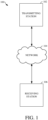
- FIG. 1 is a schematic of a video encoding and decoding system 100.
- a transmitting station 102 can be, for example, a computer having an internal configuration of hardware such as that described in FIG. 2 .
- the processing of the transmitting station 102 can be distributed among multiple devices.
- a network 104 can connect the transmitting station 102 and a receiving station 106 for encoding and decoding of the video stream.
- the video stream can be encoded in the transmitting station 102 and the encoded video stream can be decoded in the receiving station 106.
- the network 104 can be, for example, the Internet.
- the network 104 can also be a local area network (LAN), wide area network (WAN), virtual private network (VPN), cellular telephone network or any other means of transferring the video stream from the transmitting station 102 to, in this example, the receiving station 106.
- the receiving station 106 in one example, can be a computer having an internal configuration of hardware such as that described in FIG. 2 . However, other suitable implementations of the receiving station 106 are possible. For example, the processing of the receiving station 106 can be distributed among multiple devices.
- an implementation can omit the network 104.
- a video stream can be encoded and then stored for transmission at a later time to the receiving station 106 or any other device having a non-transitory storage medium or memory.
- the receiving station 106 receives (e.g., via the network 104, a computer bus, and/or some communication pathway) the encoded video stream and stores the video stream for later decoding.
- a real-time transport protocol RTP
- a transport protocol other than RTP may be used, e.g., a Hypertext Transfer Protocol (HTTP) based video streaming protocol.
- HTTP Hypertext Transfer Protocol
- the transmitting station 102 and/or the receiving station 106 may include the ability to both encode and decode a video stream as described below.
- the receiving station 106 could be a video conference participant who receives an encoded video bitstream from a video conference server (e.g., the transmitting station 102) to decode and view and further encodes and transmits its own video bitstream to the video conference server for decoding and viewing by other participants.
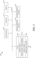
- FIG. 2 is a block diagram of an example of a computing device 200 that can implement a transmitting station or a receiving station.
- the computing device 200 can implement one or both of the transmitting station 102 and the receiving station 106 of FIG. 1 .
- the computing device 200 can be in the form of a computing system including multiple computing devices, or in the form of one computing device, for example, a mobile phone, a tablet computer, a laptop computer, a notebook computer, a desktop computer, and the like.
- a CPU 202 in the computing device 200 can be a central processing unit.
- the CPU 202 can be any other type of device, or multiple devices, capable of manipulating or processing information now-existing or hereafter developed.
- the disclosed implementations can be practiced with one processor as shown, e.g., the CPU 202, advantages in speed and efficiency can be achieved using more than one processor.
- a memory 204 in computing device 200 can be a read only memory (ROM) device or a random access memory (RAM) device in an implementation. Any other suitable type of storage device or non-transitory storage medium can be used as the memory 204.
- the memory 204 can include code and data 206 that is accessed by the CPU 202 using a bus 212.
- the memory 204 can further include an operating system 208 and application programs 210, the application programs 210 including at least one program that permits the CPU 202 to perform the methods described here.
- the application programs 210 can include applications 1 through N, which further include a video coding application that performs the methods described here.
- Computing device 200 can also include a secondary storage 214, which can, for example, be a memory card used with a mobile computing device. Because the video communication sessions may contain a significant amount of information, they can be stored in whole or in part in the secondary storage 214 and loaded into the memory 204 as needed for processing.
- the computing device 200 can also include or be in communication with an image-sensing device 220, for example a camera, or any other image-sensing device 220 now existing or hereafter developed that can sense an image such as the image of a user operating the computing device 200.
- the image-sensing device 220 can be positioned such that it is directed toward the user operating the computing device 200.
- the position and optical axis of the image-sensing device 220 can be configured such that the field of vision includes an area that is directly adjacent to the display 218 and from which the display 218 is visible.
- the computing device 200 can also include or be in communication with a sound-sensing device 222, for example a microphone, or any other sound-sensing device now existing or hereafter developed that can sense sounds near the computing device 200.
- the sound-sensing device 222 can be positioned such that it is directed toward the user operating the computing device 200 and can be configured to receive sounds, for example, speech or other utterances, made by the user while the user operates the computing device 200.
- the frame 306 may be further subdivided into blocks 310, which can contain data corresponding to, for example, 16 ⁇ 16 pixels in the frame 306.
- the blocks 310 can also be arranged to include data from one or more segments 308 of pixel data.
- the blocks 310 can also be of any other suitable size such as 4x4 pixels, 8x8 pixels, 16x8 pixels, 8x16 pixels, 16x16 pixels, or larger. Unless otherwise noted, the terms block and macroblock are used interchangeably herein.
- FIG. 5 is a block diagram of a decoder 500 according to implementations of this disclosure.
- the decoder 500 can be implemented in the receiving station 106, for example, by providing a computer software program stored in the memory 204.
- the computer software program can include machine instructions that, when executed by a processor such as the CPU 202, cause the receiving station 106 to decode video data in the manner described in FIG. 5 .
- the decoder 500 can also be implemented in hardware included in, for example, the transmitting station 102 or the receiving station 106.
- the decoder 500 similar to the reconstruction path of the encoder 400 discussed above, includes in one example the following stages to perform various functions to produce an output video stream 516 from the compressed bitstream 420: an entropy decoding stage 502, a dequantization stage 504, an inverse transform stage 506, an intra/inter prediction stage 508, a reconstruction stage 510, a loop filtering stage 512 and a post filtering stage 514.
- stages to perform various functions to produce an output video stream 516 from the compressed bitstream 420 includes in one example the following stages to perform various functions to produce an output video stream 516 from the compressed bitstream 420: an entropy decoding stage 502, a dequantization stage 504, an inverse transform stage 506, an intra/inter prediction stage 508, a reconstruction stage 510, a loop filtering stage 512 and a post filtering stage 514.
- Other structural variations of the decoder 500 can be used to decode the compressed bitstream 420.
- the data elements within the compressed bitstream 420 can be decoded by the entropy decoding stage 502 to produce a set of quantized transform coefficients.
- the dequantization stage 504 dequantizes the quantized transform coefficients (e.g., by multiplying the quantized transform coefficients by the quantizer value), and the inverse transform stage 506 inverse transforms the dequantized transform coefficients to produce a derivative residual that can be identical to that created by the inverse transform stage 412 in the encoder 400.
- the decoder 500 can use the intra/inter prediction stage 508 to create the same prediction block as was created in the encoder 400, e.g., at the intra/inter prediction stage 402.
- the prediction block can be added to the derivative residual to create a reconstructed block.
- the loop filtering stage 512 can be applied to the reconstructed block to reduce blocking artifacts.
- the post filtering stage 514 may be a deblocking filter that is applied to the reconstructed block to reduce blocking distortion.
- the result is output as the output video stream 516.
- the output video stream 516 can also be referred to as a decoded video stream, and the terms will be used interchangeably herein.
- Other variations of the decoder 500 can be used to decode the compressed bitstream 420.
- the decoder 500 can produce the output video stream 516 without the post filtering stage 514.
- a reference frame buffer may store reference frames used to encode or decode blocks of frames of a video sequence.
- reference frames may be identified as a last frame LAST_FRAME, a golden frame GOLDEN_FRAME, or an alternative reference frame ALTREF_FRAME.
- a frame header of a reference frame may include a virtual index to a location within the reference frame buffer at which the reference frame is stored.
- a reference frame mapping may map the virtual index of a reference frame to a physical index of memory at which the reference frame is stored. Where two reference frames are the same frame, those reference frames will have the same physical index even if they have different virtual indexes.
- the number and type of reference frames stored within a reference frame buffer may differ.
- the reference frames stored in a reference frame buffer can be used to identify motion vectors for predicting blocks of frames to be encoded or decoded. Different reference frames may be used depending on the type of prediction used to predict a current block of a current frame. For example, in bi-prediction, blocks of the current frame can be forward predicted using either frame stored as the LAST_FRAME or the GOLDEN_FRAME, and backward predicted using a frame stored as the ALTREF_FRAME.
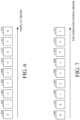
- FIG. 6 is a diagram of a group of frames in a display order of the video sequence.
- the group of frames is preceded by a frame 600, which can be referred to as a key frame or an overlay frame in some cases, and comprises eight frames 602 - 616.
- No block within the frame 600 is inter predicted using reference frames of the group of frames.
- the frame 600 is a key (also referred to as intra-predicted frame) in this example, which refers to its status that predicted blocks within the frame are only predicted using intra prediction.
- the frame 600 can be an overlay frame, which is an inter-predicted frame that can be a reconstructed frame of a previous group of frames.
- an inter-predicted frame at least some of the predicted blocks are predicted using inter prediction.
- the number of frames forming each group of frames can vary according to the video spatial / temporal characteristics and other encoded configurations, such as the key frame interval selected for random access or error resilience, for example.
- the coding order for each group of frames can differ from the display order. This allows a frame located after a current frame in the video sequence to be used as a reference frame for encoding the current frame.
- a decoder such as the decoder 500, may share a common group coding structure with an encoder, such as the encoder 400.
- the group coding structure assigns different roles that respective frames within the group may play in the reference buffer (e.g., a last frame, an alternative reference frame, etc.) and defines or indicates the coding order for the frames within a group.
- FIG. 7 is a diagram of an example of a coding order for the group of frames of FIG. 6 .
- the coding order of FIG. 7 is associated with a first group coding structure whereby a single backward reference frame is available for each frame of the group. Because the encoding and decoding order is the same, the order shown in FIG. 7 is generally referred to herein as a coding order.
- the key or overlay frame 600 is designated the golden frame in a reference frame buffer, such as the GOLDEN_FRAME in a reference frame buffer.
- the frame 600 is intra-predicted in this example, so it does not require a reference frame, but an overlay frame as the frame 600, being a reconstructed frame from a previous group, also does not use a reference frame of the current group of frames.
- the final frame 616 in the group is designated an alternative reference frame in a reference frame buffer, such as the ALTREF_FRAME.
- the frame 616 is coded out of the display order after the frame 600 so as to provide a backward reference frame for each of the remaining frames 602 - 614.
- the frame 600 serves as an available reference frame for blocks of the frame 616.
- FIG. 7 is only one example of a coding order for a group of frames. Other group coding structures may designate one or more different or additional frames for forward and/or backward prediction.
- an available reference frame may be a motion field-based reference frame portion rendered by a motion field.
- the motion field-based reference frame may be referred to as a co-located reference frame herein because the dimensions are the same as the current frame.
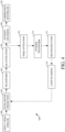
- FIG. 8 is a flowchart diagram of a method or process 800 for motion compensated prediction of a frame of a video sequence using a reference frame rendered based on a motion field.
- the process 800 can be implemented, for example, as a software program that may be executed by computing devices such as transmitting station 102 or receiving station 106.
- the software program can include machine-readable instructions that may be stored in a memory such as the memory 204 or the secondary storage 214, and that, when executed by a processor, such as CPU 202, may cause the computing device to perform the process 800.
- the process 800 can be implemented using specialized hardware or firmware. Some computing devices may have multiple memories or processors, and the operations described in the process 800 can be distributed using multiple processors, memories, or both.
- a current frame to be predicted is determined.
- Frames may be coded, and hence predicted, in any order, such as in the coding order shown in FIG. 7 .
- the frames to be predicted may also be referred to as a first, second, third, etc. frame.
- the label of first, second, etc. does not necessarily indicate an order of the frames. Instead the label is used to distinguish one current frame from another herein unless otherwise stated.
- the frame may be processed in units of blocks in a block coding order, such as a raster scan order.
- the frame may also be processed in units of blocks according to receipt of their encoded residuals within an encoded bitstream.
- forward and backward reference frames may be determined.
- the forward and backward reference frames are the nearest reconstructed frames before and after (e.g., in display order) the current frame, such as the current frame at frame index X described below.
- the process 800 may not be performed for the current frame. Instead, the current frame can be predicted according to any known technique (such as intra prediction or inter prediction using linear motion vectors).
- the process 800 can advance to 806 to determine a motion field for the current frame. Determining the motion field may include performing linear projection of the motion vectors from the reference frames, which is described in more detail with reference to FIG. 9 .
- FIG. 9 is a diagram used to explain linear projection of the motion vectors according to the teachings herein.
- the motion field of the current frame may be estimated using the nearest available reconstructed (e.g., reference) frames before and after the current frame, additional reference frames, or different reference frames.
- the current frame has a frame index X.
- the motion field of the current frame includes motion vectors from the current frame towards, in this example, reference frames Ref0, Ref1, and Ref1_Ref0, or more reference frames if available.
- the motion vectors may be stored with regard to respective 8x8 blocks of the current frame, but different size blocks, or other portions of the current frame, may be considered, e.g., in the frame scan order. In other words, the description herein uses an 8x8 block to describe the processing at 806, but this is an example only.
- the teachings may be applied to frame portions that are formed of other than blocks and to blocks of different sizes.
- the reference frame Ref0 is a reference frame that may be used for forward prediction of the current frame
- the reference frame Ref1 is a reference frame that may be used for backward prediction of the current frame.
- the immediately preceding, or last, frame 604 e.g., the reconstructed frame stored in a reference frame buffer as the LAST_FRAME
- the frame 616 e.g., the reconstructed frame stored in a reference frame buffer as the ALTREF_FRAME
- motion vectors may be projected between the pixels in the reference frames Ref0 and Ref1 to the pixels in the current frame assuming that the motion field is linear in time.
- the frame index X for the current frame is 3
- the frame index A for the reference frame Ref0 is 2
- the frame index C for the reference frame Ref1 is 8.
- the frame index C_R0 for the reference frame Ref1_Ref0 may be 1, for example.
- Linear projection may be illustrated starting with reference frame Ref1, having a frame index C.
- a motion vector MV_ref1 goes from reference frame Ref1 to the reference frame for the reference frame Ref1, namely Ref1_Ref0, whose frame index is C_R0.
- a motion vector contains two components, a row and column, to represent the spatial offset. Accordingly, the block located at (ref_row, ref_col) within reference frame Ref1 was predicted using the motion vector MV_ref1 and reference frame Ref1_Ref0 in this example.
- Block_row ref_row + MV_ref1 . row * C ⁇ X / C ⁇ C_R0 ;
- Block_col ref_col + MV_ref1.col * (C - X) / (C - C_R0), where MV_ref1.row is a first (e.g., a vertical) component of the motion vector MV_ref1, and MV_ref1.col is a second (e.g., a horizontal) component of the motion vector MV_ref1.
- the projected block position within the current frame is (Block_row, Block_col).
- MV_0.row is a first (e.g., a vertical) component of the motion vector MV_0
- MV_0.col is a second (e.g., a horizontal) component of the motion vector MV_0.
- the collection of motion vectors MV_0 and MV_1 for the blocks of the current frame forms the motion field for the current frame.
- the reference frame nearest to the current frame in natural order may be selected as the reconstructed reference frame.
- the reconstructed reference frame may be the first reference frame for forward inter prediction used to generate the motion field, the second reference frame for backward inter prediction used to generate the motion field, or some other reference frame from the video sequence.
- the frame 604 (the first reference frame) may be used as the closest reconstructed reference frame.
- the rendering may be processed in units of 8x8 blocks, for example.
- Rendering a block within the motion field-based reference frame can include applying the affine homographic model to the block to populate pixel values for pixel positions of the block.
- Rendering the block can including mapping a pixel at a pixel position (x, y) in the block towards a pixel position (x', y') in the reconstructed reference frame by applying the affine homographic model to the block according to: RB ⁇ t ⁇ ⁇ where B is the vector whose elements are the pixels positions of the block.
- the block may be co-located with a block (e.g., the current block Cur_Blk) of the frame being encoded that was used to generate the affine homographic model that is applied.
- Rendering a block within the motion field-based reference frame can include, for each pixel position in the block, using the affine homographic model to map the pixel position in the block to the pixel position within the reconstructed reference frame, and generating the block for the motion field-based reference frame by assigning a pixel value of the pixel position within the reconstructed reference frame to the pixel position in the current block.
- the processing at 808 can be repeated for each block of the motion field-based reference frame using a respective affine homographic model generated for the spatially co-located block of the frame being predicted. That is, each block comprising non-overlapping portions of the frame to be predicted can be processed to generating a respective affine homographic model for each block at 806. Then, at 808, the motion field-based reference frame may be generated by, for each of the blocks of the motion field-based reference frame, applying the respective affine homographic model for each block of the frame to a co-located block of the motion field-based reference frame to populate pixel positions within the co-located block using pixel values from the reconstructed reference frame.
- Generating the prediction block at an encoder can include performing a motion search within the motion field-based reference frame to select the best matching prediction block for the current block.
- the prediction block is generated at the encoder, the resulting residual can be further processed, such as using the lossy encoding process described with regard to the encoder 400 of FIG. 4 .
- the process 800 may form part of a rate distortion loop for the current block that uses various prediction modes, including one or more intra prediction modes and both single and compound inter prediction modes using the available prediction frames for the current frame.
- a single inter prediction mode uses only a single forward or backward reference frame for inter prediction.
- a compound inter prediction mode uses both a forward and a backward reference frame for inter prediction.
- the rate e.g., the number of bits
- the distortion may be calculated as the differences between pixel values of the block before encoding and after decoding. The differences can be a sum of absolute differences or some other measure that captures the accumulated error for blocks of the frames.
- a flag may be encoded into the bitstream to indicate whether or not a motion field-based reference frame is available for use in encoding the current frame.
- the flag may be encoded when any single block within the current frame is encoded using a motion field-based reference frame block, in an example. Where the motion field-based reference frame is available for a current frame, it is possible to include an additional flag or other indicator (e.g., at the block level) indicating whether or not the current block was encoded by inter prediction using the motion field-based reference frame.
- performing a prediction process using the motion field-based reference frame at 810 may result from a determination that a motion field-based reference frame is available for decoding the current frame.
- the determination is made by inspecting a flag that indicates that at least one block of the current frame was encoded using the motion field-based reference frame.
- a residual corresponding to a current block to be reconstructed may be decoded.
- Performing the prediction process at 810 in the decoder can include generating a prediction block for the residual. Generating the prediction block can include using an inter-prediction mode decoded from the encoded bitstream, such as from a block header.
- a flag or indicator can be decoded to determine the inter-prediction mode.
- the prediction block for the current block to be decoded is generated using pixels of the motion field-based reference frame and a motion vector mode and/or a motion vector. That is, for example, pixel positions of a prediction block may be determined using a motion vector of the prediction block that is determined from the encoded bitstream, and values for the pixel positions of the prediction block may be determined from the motion field-based reference frame.
- pixels are shown along a grid 1100 with w representing a pixel location along a first axis of the grid 1100 and with y representing a pixel location along a second axis of the grid 1100.
- the grid 1100 represents pixel locations of a portion of the current frame.
- the processing at 806 and 808 may be performed as part of the processing at 810.
- the prediction process at 810 can include finding pixel locations for the reference block used to encode the current block (e.g., from header information, such as a motion vector).
- header information such as a motion vector
- the reference block is located, all of the blocks that are spanned by (i.e., overlap) the pixel locations of the reference block are identified. This may include extending the reference block size by half of the filter length at each boundary to consider sub-pixel interpolation filters.
- the sub-pixel interpolation filter length L is used to extend the reference block to the boundaries represented by the outer dashed line 1106.
- the motion vector results in a reference block that does not align perfectly with the full-pel locations.
- the darkened area in FIG. 11 represents the full-pel locations. All of the reference blocks that overlap the full-pel locations are identified.
- a first reference block that is co-located with the current block Assuming the block sizes are the same as the current coding block 1102, a first reference block that is co-located with the current block, a second reference block that is above the first reference block, two reference blocks that extend from the left of the first reference block, and two reference blocks that extend from the left of the second reference block are identified.
- the process 800 may be performed at 806 and 808 for only some blocks within the current frame so as to produce the co-located, motion field-based reference blocks. This can include blocks within the current frame that are co-located with the identified reference blocks, plus any blocks within the current frame that are co-located with spatial neighboring block(s) not already identified that are used for forming the affine homographic model for a block.
- reference block(s) for a subsequent block may overlap one or more reference blocks identified in the decoding process of the current block.
- the motion field estimation need be performed for any of the identified blocks only once to further reduce computing requirements at the decoder.
- a reference block generated at 808 may be stored for use in decoding other blocks of the current frame. Accordingly, the motion field-based reference frame may include only some blocks with pixel values.
- the decoded residual for the current block from the encoded bitstream can be combined with the prediction block to form a reconstructed block as described by example with regard to the decoder 500 of FIG. 5 .
- the motion field effectively provides a closed boundary information for any block of interest, such that the affine homographic model can be estimated more precisely.
- the motion field rendered reference frame allows the encoder to run an effective motion search, resulting in good prediction quality.
- This co-located reference frame can be used to eliminate the use of a rendered frame may have 1 or 2 pixels offset from the current frame.
- process 800 is depicted and described as a series of steps or operations. However, the steps or operations in accordance with this disclosure can occur in various orders and/or concurrently. Additionally, other steps or operations not presented and described herein may be used. Furthermore, not all illustrated steps or operations may be required to implement a method in accordance with the disclosed subject matter.
- encoding and decoding illustrate some examples of encoding and decoding techniques. However, it is to be understood that encoding and decoding, as those terms are used in the claims, could mean compression, decompression, transformation, or any other processing or change of data.
- example is used herein to mean serving as an example, instance, or illustration. Any aspect or design described herein as “example” is not necessarily to be construed as preferred or advantageous over other aspects or designs. Rather, use of the word “example” is intended to present concepts in a concrete fashion.
- the term “or” is intended to mean an inclusive “or” rather than an exclusive “or”. That is, unless specified otherwise, or clear from context, "X includes A or B” is intended to mean any of the natural inclusive permutations. That is, if X includes A; X includes B; or X includes both A and B, then "X includes A or B" is satisfied under any of the foregoing instances.
- Implementations of the transmitting station 102 and/or the receiving station 106 can be realized in hardware, software, or any combination thereof.
- the hardware can include, for example, computers, intellectual property (IP) cores, application-specific integrated circuits (ASICs), programmable logic arrays, optical processors, programmable logic controllers, microcode, microcontrollers, servers, microprocessors, digital signal processors or any other suitable circuit.
- IP intellectual property
- ASICs application-specific integrated circuits
- programmable logic arrays optical processors
- programmable logic controllers programmable logic controllers
- microcode microcontrollers
- servers microprocessors, digital signal processors or any other suitable circuit.
- signal processors digital signal processors or any other suitable circuit.
- the transmitting station 102 or the receiving station 106 can be implemented using a general purpose computer or general purpose processor with a computer program that, when executed, carries out any of the respective methods, algorithms and/or instructions described herein.
- a special purpose computer/processor can be utilized that contains other hardware for carrying out any of the methods, algorithms, or instructions described herein.
- the transmitting station 102 and the receiving station 106 can, for example, be implemented on computers in a video conferencing system.
- the transmitting station 102 can be implemented on a server and the receiving station 106 can be implemented on a device separate from the server, such as a hand-held communications device.
- the transmitting station 102 can encode content using an encoder 400 into an encoded video signal and transmit the encoded video signal to the communications device.
- the communications device can then decode the encoded video signal using a decoder 500.
- the communications device can decode content stored locally on the communications device, for example, content that was not transmitted by the transmitting station 102.
- the receiving station 106 can be a generally stationary personal computer rather than a portable communications device and/or a device including an encoder 400 may also include a decoder 500.
- implementations of the present disclosure can take the form of a computer program product accessible from, for example, a computer-usable or computer-readable medium.
- a computer-usable or computer-readable medium can be any device that can, for example, tangibly contain, store, communicate, or transport the program for use by or in connection with any processor.
- the medium can be, for example, an electronic, magnetic, optical, electromagnetic, or a semiconductor device. Other suitable mediums are also available.
Landscapes
- Engineering & Computer Science (AREA)
- Multimedia (AREA)
- Signal Processing (AREA)
- Compression Or Coding Systems Of Tv Signals (AREA)
Claims (15)
- Procédé, comprenant :la détermination d'une première trame à prédire, la première trame étant dans une séquence vidéo ;la détermination d'une première trame de référence à partir de la séquence vidéo pour une inter-prédiction aval de la première trame ;la détermination d'une seconde trame de référence à partir de la séquence vidéo pour une inter-prédiction amont de la première trame ;la détermination d'un champ de mouvement respectif pour chacun d'au moins certains blocs de la première trame en utilisant au moins l'une de la première trame de référence et de la seconde trame de référence ;la détermination des paramètres formant un modèle homographique affine pour un bloc de la première trame en utilisant le champ de mouvement pour le bloc de la première trame, dans lequel le modèle homographique affine mappe le bloc de la première trame à des pixels dans une trame de référence reconstruite, le modèle homographique affine comprenant une matrice de paramètres définissant une rotation et un vecteur associé définissant une translation, qui sont obtenus à la suite d'un processus d'optimisation défini par une fonction objective ;la génération d'une trame de référence basée sur un champ de mouvement, dans lequel la génération d'une trame de référence basée sur un champ de mouvement comporte la génération d'un bloc de la trame de référence basée sur un champ de mouvement qui est colocalisé avec le bloc de la première trame en appliquant le modèle homographique affine au bloc pour renseigner les valeurs de pixels de la trame de référence reconstruite ; etla réalisation d'un processus de prédiction pour la première trame en utilisant la trame de référence basée sur un champ de mouvement.
- Procédé selon la revendication 1, dans lequel la détermination du champ de mouvement comprend :la réalisation d'une projection linéaire en utilisant des vecteurs de mouvement de l'une de la première trame de référence ou de la seconde trame de référence ; eten utilisant la projection linéaire pour déterminer les vecteurs de mouvement se prolongeant des blocs de la première trame à au moins l'une de la première trame de référence ou de la seconde trame de référence.
- Procédé selon la revendication 1, dans lequel la détermination du champ de mouvement comprend :la projection d'un vecteur de mouvement pour prédire un bloc de la seconde trame de référence sur une trame actuelle afin de définir une position de bloc projetée dans la première trame ;l'estimation d'un vecteur de mouvement à partir de la position de bloc projetée vers la première trame de référence en utilisant le vecteur de mouvement pour prédire le bloc de la seconde trame de référence ; etl'estimation d'un vecteur de mouvement à partir de la position de bloc projetée vers la seconde trame de référence en utilisant le vecteur de mouvement pour prédire le bloc de la seconde trame de référence.
- Procédé selon la revendication 3, dans lequel :le vecteur de mouvement pour prédire le bloc de la seconde trame de référence est associé à une trame de référence pour prédire la seconde trame de référence ayant un indice de trame de référence,la trame actuelle a un indice de trame actuelle,la première trame de référence a un premier indice de trame de référence,la seconde trame de référence a un second indice de trame de référence,l'estimation du vecteur de mouvement à partir de la position de bloc projetée vers la première trame de référence comprend la modification du vecteur de mouvement pour prédire le bloc de la seconde trame de référence en utilisant l'indice de trame de référence, l'indice de trame actuelle, le premier indice de trame et le second indice de trame ; etl'estimation du vecteur de mouvement à partir de la position de bloc projetée vers la seconde trame de référence comprend la modification du vecteur de mouvement pour prédire le bloc de la seconde trame de référence en utilisant l'indice de trame de référence, l'indice de trame actuelle, le premier indice de trame et le second indice de trame.
- Procédé selon l'une quelconque des revendications 1 à 4, dans lequel le rendu du bloc actuel comprend, pour chaque position de pixel dans le bloc actuel :en utilisant le modèle homographique affine pour mapper la position de pixel dans le bloc actuel à une position de pixel dans la trame de référence reconstruite ; etla génération du bloc pour la trame de référence basée sur un champ de mouvement en attribuant une valeur de pixel de la position de pixel dans la trame de référence reconstruite à la position de pixel dans le bloc actuel ; éventuellement, dans lequel la détermination du champ de mouvement respectif pour les blocs de la trame actuelle comprend l'hypothèse que chaque champ de mouvement pour un bloc est linéaire dans le temps.
- Procédé selon l'une quelconque des revendications 1 à 5, dans lequel la trame de référence reconstruite est l'une de la première trame de référence ou de la seconde trame de référence ; et/ou
dans lequel la réalisation du processus de prédiction pour la première trame en utilisant la trame de référence basée sur un champ de mouvement comprend la réalisation d'une recherche de mouvement dans la trame de référence basée sur un champ de mouvement pour un premier bloc à prédire qui se trouve dans la première trame. - Procédé selon l'une quelconque des revendications 1 à 6, comprenant également :
la détermination d'un premier vecteur de mouvement utilisé pour coder un premier bloc de la première trame, dans lequel :
la détermination du champ de mouvement respectif pour les blocs de la première trame comprend la détermination d'un champ de mouvement respectif pour chaque bloc de la première trame qui chevauche les positions de pixel identifiées par le premier vecteur de mouvement. - Procédé selon l'une quelconque des revendications 1 à 7, dans lequel la détermination des paramètres formant le modèle homographique affine en utilisant le champ de mouvement comprend, pour le bloc de la première trame, la détermination des paramètres formant le modèle homographique affine pour le bloc en utilisant les positions centrales du bloc et au moins deux blocs voisins et en utilisant le champ de mouvement du bloc et les au moins deux blocs voisins.
- Appareil, comprenant :un processeur ; etun support de stockage non transitoire qui comporte des instructions exécutables par le processeur pour mettre en œuvre un procédé comprenant :la détermination d'une première trame à prédire, la première trame étant dans une séquence vidéo ;la détermination d'un champ de mouvement respectif pour chacun d'au moins certains blocs de la première trame en utilisant au moins l'une d'une première trame de référence de la séquence vidéo pour l'inter-prédiction aval de la première trame ou une seconde trame de référence de la séquence vidéo pour l'inter-prédiction amont de la première trame ;la détermination des paramètres formant un modèle homographique affine pour un bloc de la première trame en utilisant le champ de mouvement pour le bloc de la première trame, dans lequel le modèle homographique affine mappe le bloc de la première trame à des pixels dans une trame de référence reconstruite, le modèle homographique affine comprenant une matrice de paramètres définissant une rotation et un vecteur associé définissant une translation, qui sont obtenus à la suite d'un processus d'optimisation défini par une fonction objective ;la génération d'une trame de référence basée sur un champ de mouvement, dans lequel la génération d'une trame de référence basée sur un champ de mouvement comporte la génération d'un bloc de la trame de référence basée sur un champ de mouvement qui est colocalisé avec le bloc de la première trame en appliquant le modèle homographique affine au bloc pour renseigner les valeurs de pixels de la trame de référence reconstruite ; etla réalisation d'un processus de prédiction pour la première trame en utilisant la trame de référence basée sur un champ de mouvement.
- Appareil selon la revendication 9, dans lequel les instructions pour générer le bloc de la trame de référence basée sur un champ de mouvement comprennent des instructions pour appliquer le modèle homographique affine au bloc en mappant une valeur de pixel à une position de pixel dans la trame de référence reconstruite à une position de pixel dans le bloc selon :
 B est un vecteur dont les éléments sont des emplacements de pixel dans le bloc ;Γ est un vecteur 1×5 dont les entrées sont toutes des uns ;
 a, b, c, d, e et f sont les paramètres, qui sont des valeurs entières.
 - Appareil selon la revendication 9 ou 10, dans lequel le modèle homographique affine comprend une matrice à 6 paramètres.
- Appareil selon l'une quelconque des revendications 9 à 11, dans lequel :les au moins certains des blocs de la première trame comprennent tous les blocs de la première trame, chaque bloc comprenant des parties ne se chevauchant pas de la première trame,les instructions pour déterminer les paramètres formant un modèle homographique affine comprennent des instructions pour générer un modèle homographique affine respectif pour chaque bloc de la première trame, etles instructions de rendu du bloc de la trame de référence basée sur un champ de mouvement comprennent, pour chacun des blocs de la trame de référence basée sur un champ de mouvement :l'application du modèle homographique affine respectif pour chaque bloc de la première trame à un bloc colocalisé de la trame de référence basée sur un champ de mouvement pour renseigner les positions de pixel dans le bloc colocalisé en utilisant des valeurs de pixel provenant d'une trame de référence reconstruite ; et/oudans lequel les instructions pour réaliser le processus de prédiction pour la première trame en utilisant la trame de référence basée sur un champ de mouvement comprennent des instructions pour réaliser une recherche de mouvement dans la trame de référence basée sur un champ de mouvement pour un bloc dans la première trame à prédire.
- Appareil selon l'une quelconque des revendications 9 à 12, dans lequel les instructions comprennent également des instructions pour :
décoder un résidu correspondant à un premier bloc à reconstruire, dans lequel la réalisation du processus de prédiction pour la première trame en utilisant la trame de référence basée sur un champ de mouvement comprend :la détermination de positions de pixel d'un bloc de prédiction du premier bloc en utilisant un vecteur de mouvement du premier bloc ; etla détermination de valeurs des positions de pixel du bloc de prédiction à partir de la trame de référence basée sur un champ de mouvement. - Appareil selon l'une quelconque des revendications 9 à 13, dans lequel les instructions pour déterminer des paramètres du modèle homographique affine en utilisant le champ de mouvement comprennent des instructions, pour un bloc de la première trame, afin de déterminer les paramètres formant le modèle homographique affine pour le bloc en utilisant une position de pixel centrale et un champ de mouvement du bloc, une position de pixel centrale et un champ de mouvement d'un premier bloc voisin situé au-dessus du bloc, une position de pixel centrale et un champ de mouvement d'un deuxième bloc voisin situé en dessous du bloc, une position de pixel centrale et un champ de mouvement d'un troisième bloc voisin situé à gauche du bloc, une position de pixel centrale et un champ de mouvement d'un quatrième bloc voisin situé à droite du bloc.
- Appareil selon l'une quelconque des revendications 9 à 14, dans lequel la trame de référence reconstruite est une trame reconstruite de la séquence vidéo la plus proche de la première trame.
Applications Claiming Priority (3)
| Application Number | Priority Date | Filing Date | Title |
|---|---|---|---|
| US201762588505P | 2017-11-20 | 2017-11-20 | |
| US15/893,978 US11025950B2 (en) | 2017-11-20 | 2018-02-12 | Motion field-based reference frame rendering for motion compensated prediction in video coding |
| PCT/US2018/047223 WO2019099084A1 (fr) | 2017-11-20 | 2018-08-21 | Rendu de trame de référence basée sur un champ de mouvement pour une prédiction à compensation de mouvement en codage vidéo |
Publications (2)
| Publication Number | Publication Date |
|---|---|
| EP3714601A1 EP3714601A1 (fr) | 2020-09-30 |
| EP3714601B1 true EP3714601B1 (fr) | 2025-03-05 |
Family
ID=66533557
Family Applications (1)
| Application Number | Title | Priority Date | Filing Date |
|---|---|---|---|
| EP18769923.6A Active EP3714601B1 (fr) | 2017-11-20 | 2018-08-21 | Rendu de trame de référence basée sur un champ de mouvement pour une prédiction à compensation de mouvement en codage vidéo |
Country Status (4)
| Country | Link |
|---|---|
| US (1) | US11025950B2 (fr) |
| EP (1) | EP3714601B1 (fr) |
| CN (1) | CN110692246B (fr) |
| WO (1) | WO2019099084A1 (fr) |
Families Citing this family (10)
| Publication number | Priority date | Publication date | Assignee | Title |
|---|---|---|---|---|
| US11070813B2 (en) * | 2018-06-29 | 2021-07-20 | Intel Corporation | Global motion estimation and modeling for accurate global motion compensation for efficient video processing or coding |
| US11665365B2 (en) * | 2018-09-14 | 2023-05-30 | Google Llc | Motion prediction coding with coframe motion vectors |
| CN114208186B (zh) | 2019-07-25 | 2023-12-22 | 北京字节跳动网络技术有限公司 | 帧内块复制虚拟缓冲区的尺寸限制 |
| BR112022001305A2 (pt) * | 2019-07-25 | 2022-03-22 | Beijing Bytedance Network Tech Co Ltd | Método para processamento de vídeo, aparelho de processamento de vídeo, e, meio legível por computador |
| CN113676735A (zh) * | 2019-09-23 | 2021-11-19 | 杭州海康威视数字技术股份有限公司 | 编解码方法方法、装置及设备 |
| KR102735189B1 (ko) | 2019-09-23 | 2024-11-28 | 두인 비전 컴퍼니 리미티드 | 가상 파이프라인 데이터 유닛에 기초한 인트라 블록 복사 가상 버퍼의 설정 |
| WO2021185306A1 (fr) | 2020-03-18 | 2021-09-23 | Beijing Bytedance Network Technology Co., Ltd. | Mémoire tampon de copie intra-bloc et mise à jour de prédicteur de palette |
| CN113556567B (zh) * | 2020-04-24 | 2022-11-25 | 华为技术有限公司 | 帧间预测的方法和装置 |
| CN113068041B (zh) * | 2021-03-12 | 2022-02-08 | 天津大学 | 一种智能仿射运动补偿编码方法 |
| CN121397163B (zh) * | 2025-12-23 | 2026-03-24 | 瀚博半导体(上海)股份有限公司 | 视频处理方法、装置、计算设备、介质及程序产品 |
Family Cites Families (7)
| Publication number | Priority date | Publication date | Assignee | Title |
|---|---|---|---|---|
| US6285711B1 (en) * | 1998-05-20 | 2001-09-04 | Sharp Laboratories Of America, Inc. | Block matching-based method for estimating motion fields and global affine motion parameters in digital video sequences |
| CN103026707B (zh) * | 2010-07-21 | 2016-11-09 | 杜比实验室特许公司 | 使用用于视频编码的高级运动模型的参考处理 |
| US20150015792A1 (en) * | 2012-03-05 | 2015-01-15 | Thomson Licensing | Filtering a displacement field between video frames |
| WO2014122131A1 (fr) * | 2013-02-05 | 2014-08-14 | Thomson Licensing | Procédé pour générer un champ de mouvement pour une séquence vidéo |
| US9230303B2 (en) * | 2013-04-16 | 2016-01-05 | The United States Of America, As Represented By The Secretary Of The Navy | Multi-frame super-resolution of image sequence with arbitrary motion patterns |
| CN107240147B (zh) * | 2017-05-26 | 2020-01-14 | 清华大学 | 图像渲染方法及系统 |
| US10511852B1 (en) * | 2018-07-13 | 2019-12-17 | Tencent America LLC | Method and apparatus for video coding |
-
2018
- 2018-02-12 US US15/893,978 patent/US11025950B2/en active Active
- 2018-08-21 CN CN201880036760.4A patent/CN110692246B/zh active Active
- 2018-08-21 WO PCT/US2018/047223 patent/WO2019099084A1/fr not_active Ceased
- 2018-08-21 EP EP18769923.6A patent/EP3714601B1/fr active Active
Also Published As
| Publication number | Publication date |
|---|---|
| WO2019099084A1 (fr) | 2019-05-23 |
| EP3714601A1 (fr) | 2020-09-30 |
| CN110692246A (zh) | 2020-01-14 |
| CN110692246B (zh) | 2023-01-03 |
| US20190158873A1 (en) | 2019-05-23 |
| US11025950B2 (en) | 2021-06-01 |
Similar Documents
| Publication | Publication Date | Title |
|---|---|---|
| US12244818B2 (en) | Selective reference block generation without full reference frame generation | |
| EP3714601B1 (fr) | Rendu de trame de référence basée sur un champ de mouvement pour une prédiction à compensation de mouvement en codage vidéo | |
| US10986361B2 (en) | Video coding using reference motion vectors | |
| US10555000B2 (en) | Multi-level compound prediction | |
| US11284107B2 (en) | Co-located reference frame interpolation using optical flow estimation | |
| EP3622712B1 (fr) | Vecteurs de mouvement de référence déformés pour compression vidéo | |
| WO2019040134A1 (fr) | Estimation de flux optique pour prédiction à compensation de mouvement en codage vidéo | |
| GB2548450A (en) | Motion vector prediction through scaling | |
| US12206842B2 (en) | Motion field estimation based on motion trajectory derivation | |
| US8908767B1 (en) | Temporal motion vector prediction | |
| EP3744101B1 (fr) | Filtrage temporel adaptatif pour rendu de trame de référence alternative | |
| US10448013B2 (en) | Multi-layer-multi-reference prediction using adaptive temporal filtering | |
| US20250301147A1 (en) | Local Motion Extension In Video Coding | |
| US20250287032A1 (en) | Motion Refinement For A Co-Located Reference Frame |
Legal Events
| Date | Code | Title | Description |
|---|---|---|---|
| STAA | Information on the status of an ep patent application or granted ep patent |
Free format text: STATUS: UNKNOWN |
|
| STAA | Information on the status of an ep patent application or granted ep patent |
Free format text: STATUS: THE INTERNATIONAL PUBLICATION HAS BEEN MADE |
|
| PUAI | Public reference made under article 153(3) epc to a published international application that has entered the european phase |
Free format text: ORIGINAL CODE: 0009012 |
|
| STAA | Information on the status of an ep patent application or granted ep patent |
Free format text: STATUS: REQUEST FOR EXAMINATION WAS MADE |
|
| 17P | Request for examination filed |
Effective date: 20191213 |
|
| AK | Designated contracting states |
Kind code of ref document: A1 Designated state(s): AL AT BE BG CH CY CZ DE DK EE ES FI FR GB GR HR HU IE IS IT LI LT LU LV MC MK MT NL NO PL PT RO RS SE SI SK SM TR |
|
| AX | Request for extension of the european patent |
Extension state: BA ME |
|
| DAV | Request for validation of the european patent (deleted) | ||
| DAX | Request for extension of the european patent (deleted) | ||
| STAA | Information on the status of an ep patent application or granted ep patent |
Free format text: STATUS: EXAMINATION IS IN PROGRESS |
|
| 17Q | First examination report despatched |
Effective date: 20221129 |
|
| GRAP | Despatch of communication of intention to grant a patent |
Free format text: ORIGINAL CODE: EPIDOSNIGR1 |
|
| STAA | Information on the status of an ep patent application or granted ep patent |
Free format text: STATUS: GRANT OF PATENT IS INTENDED |
|
| RIC1 | Information provided on ipc code assigned before grant |
Ipc: H04N 19/51 20140101ALI20240912BHEP Ipc: H04N 19/577 20140101ALI20240912BHEP Ipc: H04N 19/567 20140101ALI20240912BHEP Ipc: H04N 19/147 20140101ALI20240912BHEP Ipc: H04N 19/70 20140101ALI20240912BHEP Ipc: H04N 19/176 20140101AFI20240912BHEP |
|
| INTG | Intention to grant announced |
Effective date: 20240925 |
|
| GRAS | Grant fee paid |
Free format text: ORIGINAL CODE: EPIDOSNIGR3 |
|
| GRAA | (expected) grant |
Free format text: ORIGINAL CODE: 0009210 |
|
| STAA | Information on the status of an ep patent application or granted ep patent |
Free format text: STATUS: THE PATENT HAS BEEN GRANTED |
|
| P01 | Opt-out of the competence of the unified patent court (upc) registered |
Free format text: CASE NUMBER: APP_1341/2025 Effective date: 20250109 |
|
| AK | Designated contracting states |
Kind code of ref document: B1 Designated state(s): AL AT BE BG CH CY CZ DE DK EE ES FI FR GB GR HR HU IE IS IT LI LT LU LV MC MK MT NL NO PL PT RO RS SE SI SK SM TR |
|
| REG | Reference to a national code |
Ref country code: GB Ref legal event code: FG4D |
|
| REG | Reference to a national code |
Ref country code: CH Ref legal event code: EP |
|
| REG | Reference to a national code |
Ref country code: DE Ref legal event code: R096 Ref document number: 602018079823 Country of ref document: DE |
|
| REG | Reference to a national code |
Ref country code: IE Ref legal event code: FG4D |
|
| PG25 | Lapsed in a contracting state [announced via postgrant information from national office to epo] |
Ref country code: RS Free format text: LAPSE BECAUSE OF FAILURE TO SUBMIT A TRANSLATION OF THE DESCRIPTION OR TO PAY THE FEE WITHIN THE PRESCRIBED TIME-LIMIT Effective date: 20250605 |
|
| PG25 | Lapsed in a contracting state [announced via postgrant information from national office to epo] |
Ref country code: FI Free format text: LAPSE BECAUSE OF FAILURE TO SUBMIT A TRANSLATION OF THE DESCRIPTION OR TO PAY THE FEE WITHIN THE PRESCRIBED TIME-LIMIT Effective date: 20250305 |
|
| REG | Reference to a national code |
Ref country code: NL Ref legal event code: MP Effective date: 20250305 |
|
| PG25 | Lapsed in a contracting state [announced via postgrant information from national office to epo] |
Ref country code: ES Free format text: LAPSE BECAUSE OF FAILURE TO SUBMIT A TRANSLATION OF THE DESCRIPTION OR TO PAY THE FEE WITHIN THE PRESCRIBED TIME-LIMIT Effective date: 20250305 |
|
| REG | Reference to a national code |
Ref country code: LT Ref legal event code: MG9D |
|
| PG25 | Lapsed in a contracting state [announced via postgrant information from national office to epo] |
Ref country code: NO Free format text: LAPSE BECAUSE OF FAILURE TO SUBMIT A TRANSLATION OF THE DESCRIPTION OR TO PAY THE FEE WITHIN THE PRESCRIBED TIME-LIMIT Effective date: 20250605 |
|
| PG25 | Lapsed in a contracting state [announced via postgrant information from national office to epo] |
Ref country code: HR Free format text: LAPSE BECAUSE OF FAILURE TO SUBMIT A TRANSLATION OF THE DESCRIPTION OR TO PAY THE FEE WITHIN THE PRESCRIBED TIME-LIMIT Effective date: 20250305 |
|
| PG25 | Lapsed in a contracting state [announced via postgrant information from national office to epo] |
Ref country code: LV Free format text: LAPSE BECAUSE OF FAILURE TO SUBMIT A TRANSLATION OF THE DESCRIPTION OR TO PAY THE FEE WITHIN THE PRESCRIBED TIME-LIMIT Effective date: 20250305 |
|
| PG25 | Lapsed in a contracting state [announced via postgrant information from national office to epo] |
Ref country code: GR Free format text: LAPSE BECAUSE OF FAILURE TO SUBMIT A TRANSLATION OF THE DESCRIPTION OR TO PAY THE FEE WITHIN THE PRESCRIBED TIME-LIMIT Effective date: 20250606 Ref country code: BG Free format text: LAPSE BECAUSE OF FAILURE TO SUBMIT A TRANSLATION OF THE DESCRIPTION OR TO PAY THE FEE WITHIN THE PRESCRIBED TIME-LIMIT Effective date: 20250305 |
|
| REG | Reference to a national code |
Ref country code: AT Ref legal event code: MK05 Ref document number: 1774027 Country of ref document: AT Kind code of ref document: T Effective date: 20250305 |
|
| PG25 | Lapsed in a contracting state [announced via postgrant information from national office to epo] |
Ref country code: NL Free format text: LAPSE BECAUSE OF FAILURE TO SUBMIT A TRANSLATION OF THE DESCRIPTION OR TO PAY THE FEE WITHIN THE PRESCRIBED TIME-LIMIT Effective date: 20250305 |
|
| PG25 | Lapsed in a contracting state [announced via postgrant information from national office to epo] |
Ref country code: SE Free format text: LAPSE BECAUSE OF FAILURE TO SUBMIT A TRANSLATION OF THE DESCRIPTION OR TO PAY THE FEE WITHIN THE PRESCRIBED TIME-LIMIT Effective date: 20250305 |
|
| PG25 | Lapsed in a contracting state [announced via postgrant information from national office to epo] |
Ref country code: SM Free format text: LAPSE BECAUSE OF FAILURE TO SUBMIT A TRANSLATION OF THE DESCRIPTION OR TO PAY THE FEE WITHIN THE PRESCRIBED TIME-LIMIT Effective date: 20250305 |
|
| PG25 | Lapsed in a contracting state [announced via postgrant information from national office to epo] |
Ref country code: PT Free format text: LAPSE BECAUSE OF FAILURE TO SUBMIT A TRANSLATION OF THE DESCRIPTION OR TO PAY THE FEE WITHIN THE PRESCRIBED TIME-LIMIT Effective date: 20250707 |
|
| PGFP | Annual fee paid to national office [announced via postgrant information from national office to epo] |
Ref country code: DE Payment date: 20250827 Year of fee payment: 8 |
|
| PG25 | Lapsed in a contracting state [announced via postgrant information from national office to epo] |
Ref country code: PL Free format text: LAPSE BECAUSE OF FAILURE TO SUBMIT A TRANSLATION OF THE DESCRIPTION OR TO PAY THE FEE WITHIN THE PRESCRIBED TIME-LIMIT Effective date: 20250305 Ref country code: IT Free format text: LAPSE BECAUSE OF FAILURE TO SUBMIT A TRANSLATION OF THE DESCRIPTION OR TO PAY THE FEE WITHIN THE PRESCRIBED TIME-LIMIT Effective date: 20250305 |
|
| PGFP | Annual fee paid to national office [announced via postgrant information from national office to epo] |
Ref country code: GB Payment date: 20250827 Year of fee payment: 8 |
|
| PG25 | Lapsed in a contracting state [announced via postgrant information from national office to epo] |
Ref country code: AT Free format text: LAPSE BECAUSE OF FAILURE TO SUBMIT A TRANSLATION OF THE DESCRIPTION OR TO PAY THE FEE WITHIN THE PRESCRIBED TIME-LIMIT Effective date: 20250305 |
|
| PG25 | Lapsed in a contracting state [announced via postgrant information from national office to epo] |
Ref country code: CZ Free format text: LAPSE BECAUSE OF FAILURE TO SUBMIT A TRANSLATION OF THE DESCRIPTION OR TO PAY THE FEE WITHIN THE PRESCRIBED TIME-LIMIT Effective date: 20250305 Ref country code: EE Free format text: LAPSE BECAUSE OF FAILURE TO SUBMIT A TRANSLATION OF THE DESCRIPTION OR TO PAY THE FEE WITHIN THE PRESCRIBED TIME-LIMIT Effective date: 20250305 |
|
| PG25 | Lapsed in a contracting state [announced via postgrant information from national office to epo] |
Ref country code: RO Free format text: LAPSE BECAUSE OF FAILURE TO SUBMIT A TRANSLATION OF THE DESCRIPTION OR TO PAY THE FEE WITHIN THE PRESCRIBED TIME-LIMIT Effective date: 20250305 |
|
| PG25 | Lapsed in a contracting state [announced via postgrant information from national office to epo] |
Ref country code: SK Free format text: LAPSE BECAUSE OF FAILURE TO SUBMIT A TRANSLATION OF THE DESCRIPTION OR TO PAY THE FEE WITHIN THE PRESCRIBED TIME-LIMIT Effective date: 20250305 |
|
| PG25 | Lapsed in a contracting state [announced via postgrant information from national office to epo] |
Ref country code: IS Free format text: LAPSE BECAUSE OF FAILURE TO SUBMIT A TRANSLATION OF THE DESCRIPTION OR TO PAY THE FEE WITHIN THE PRESCRIBED TIME-LIMIT Effective date: 20250705 |
|
| REG | Reference to a national code |
Ref country code: DE Ref legal event code: R097 Ref document number: 602018079823 Country of ref document: DE |
|
| PLBE | No opposition filed within time limit |
Free format text: ORIGINAL CODE: 0009261 |
|
| STAA | Information on the status of an ep patent application or granted ep patent |
Free format text: STATUS: NO OPPOSITION FILED WITHIN TIME LIMIT |
|
| PG25 | Lapsed in a contracting state [announced via postgrant information from national office to epo] |
Ref country code: DK Free format text: LAPSE BECAUSE OF FAILURE TO SUBMIT A TRANSLATION OF THE DESCRIPTION OR TO PAY THE FEE WITHIN THE PRESCRIBED TIME-LIMIT Effective date: 20250305 |
|
| REG | Reference to a national code |
Ref country code: CH Ref legal event code: L10 Free format text: ST27 STATUS EVENT CODE: U-0-0-L10-L00 (AS PROVIDED BY THE NATIONAL OFFICE) Effective date: 20260114 |
|
| 26N | No opposition filed |
Effective date: 20251208 |
|
| REG | Reference to a national code |
Ref country code: CH Ref legal event code: H13 Free format text: ST27 STATUS EVENT CODE: U-0-0-H10-H13 (AS PROVIDED BY THE NATIONAL OFFICE) Effective date: 20260324 |
|
| PG25 | Lapsed in a contracting state [announced via postgrant information from national office to epo] |
Ref country code: MC Free format text: LAPSE BECAUSE OF FAILURE TO SUBMIT A TRANSLATION OF THE DESCRIPTION OR TO PAY THE FEE WITHIN THE PRESCRIBED TIME-LIMIT Effective date: 20250305 |
|
| PG25 | Lapsed in a contracting state [announced via postgrant information from national office to epo] |
Ref country code: LU Free format text: LAPSE BECAUSE OF NON-PAYMENT OF DUE FEES Effective date: 20250821 |
|
| PG25 | Lapsed in a contracting state [announced via postgrant information from national office to epo] |
Ref country code: CH Free format text: LAPSE BECAUSE OF NON-PAYMENT OF DUE FEES Effective date: 20250831 |