EP3714667B1 - Module électrique de puissance - Google Patents
Module électrique de puissance Download PDFInfo
- Publication number
- EP3714667B1 EP3714667B1 EP18803422.7A EP18803422A EP3714667B1 EP 3714667 B1 EP3714667 B1 EP 3714667B1 EP 18803422 A EP18803422 A EP 18803422A EP 3714667 B1 EP3714667 B1 EP 3714667B1
- Authority
- EP
- European Patent Office
- Prior art keywords
- electrical power
- power module
- support
- module according
- supports
- Prior art date
- Legal status (The legal status is an assumption and is not a legal conclusion. Google has not performed a legal analysis and makes no representation as to the accuracy of the status listed.)
- Active
Links
Images


Classifications
-
- H—ELECTRICITY
- H05—ELECTRIC TECHNIQUES NOT OTHERWISE PROVIDED FOR
- H05K—PRINTED CIRCUITS; CASINGS OR CONSTRUCTIONAL DETAILS OF ELECTRIC APPARATUS; MANUFACTURE OF ASSEMBLAGES OF ELECTRICAL COMPONENTS
- H05K7/00—Constructional details common to different types of electric apparatus
- H05K7/20—Modifications to facilitate cooling, ventilating, or heating
- H05K7/2089—Modifications to facilitate cooling, ventilating, or heating for power electronics, e.g. for inverters for controlling motor
- H05K7/209—Heat transfer by conduction from internal heat source to heat radiating structure
-
- H—ELECTRICITY
- H02—GENERATION; CONVERSION OR DISTRIBUTION OF ELECTRIC POWER
- H02M—APPARATUS FOR CONVERSION BETWEEN AC AND AC, BETWEEN AC AND DC, OR BETWEEN DC AND DC, AND FOR USE WITH MAINS OR SIMILAR POWER SUPPLY SYSTEMS; CONVERSION OF DC OR AC INPUT POWER INTO SURGE OUTPUT POWER; CONTROL OR REGULATION THEREOF
- H02M7/00—Conversion of AC power input into DC power output; Conversion of DC power input into AC power output
- H02M7/003—Constructional details, e.g. physical layout, assembly, wiring or busbar connections
-
- H—ELECTRICITY
- H02—GENERATION; CONVERSION OR DISTRIBUTION OF ELECTRIC POWER
- H02P—CONTROL OR REGULATION OF ELECTRIC MOTORS, ELECTRIC GENERATORS OR DYNAMO-ELECTRIC CONVERTERS; CONTROLLING TRANSFORMERS, REACTORS OR CHOKE COILS
- H02P27/00—Arrangements or methods for the control of AC motors characterised by the kind of supply voltage
- H02P27/04—Arrangements or methods for the control of AC motors characterised by the kind of supply voltage using variable-frequency supply voltage, e.g. inverter or converter supply voltage
- H02P27/06—Arrangements or methods for the control of AC motors characterised by the kind of supply voltage using variable-frequency supply voltage, e.g. inverter or converter supply voltage using DC to AC converters or inverters
-
- H—ELECTRICITY
- H05—ELECTRIC TECHNIQUES NOT OTHERWISE PROVIDED FOR
- H05K—PRINTED CIRCUITS; CASINGS OR CONSTRUCTIONAL DETAILS OF ELECTRIC APPARATUS; MANUFACTURE OF ASSEMBLAGES OF ELECTRICAL COMPONENTS
- H05K1/00—Printed circuits
- H05K1/02—Details
- H05K1/0272—Adaptations for fluid transport, e.g. channels, holes
-
- H—ELECTRICITY
- H05—ELECTRIC TECHNIQUES NOT OTHERWISE PROVIDED FOR
- H05K—PRINTED CIRCUITS; CASINGS OR CONSTRUCTIONAL DETAILS OF ELECTRIC APPARATUS; MANUFACTURE OF ASSEMBLAGES OF ELECTRICAL COMPONENTS
- H05K1/00—Printed circuits
- H05K1/18—Printed circuits structurally associated with non-printed electric components
- H05K1/181—Printed circuits structurally associated with non-printed electric components associated with surface mounted components
-
- H—ELECTRICITY
- H05—ELECTRIC TECHNIQUES NOT OTHERWISE PROVIDED FOR
- H05K—PRINTED CIRCUITS; CASINGS OR CONSTRUCTIONAL DETAILS OF ELECTRIC APPARATUS; MANUFACTURE OF ASSEMBLAGES OF ELECTRICAL COMPONENTS
- H05K7/00—Constructional details common to different types of electric apparatus
- H05K7/14—Mounting supporting structure in casing or on frame or rack
- H05K7/1422—Printed circuit boards receptacles, e.g. stacked structures, electronic circuit modules or box like frames
- H05K7/1427—Housings
-
- H—ELECTRICITY
- H05—ELECTRIC TECHNIQUES NOT OTHERWISE PROVIDED FOR
- H05K—PRINTED CIRCUITS; CASINGS OR CONSTRUCTIONAL DETAILS OF ELECTRIC APPARATUS; MANUFACTURE OF ASSEMBLAGES OF ELECTRICAL COMPONENTS
- H05K7/00—Constructional details common to different types of electric apparatus
- H05K7/20—Modifications to facilitate cooling, ventilating, or heating
- H05K7/2089—Modifications to facilitate cooling, ventilating, or heating for power electronics, e.g. for inverters for controlling motor
- H05K7/20909—Forced ventilation, e.g. on heat dissipaters coupled to components
-
- H—ELECTRICITY
- H05—ELECTRIC TECHNIQUES NOT OTHERWISE PROVIDED FOR
- H05K—PRINTED CIRCUITS; CASINGS OR CONSTRUCTIONAL DETAILS OF ELECTRIC APPARATUS; MANUFACTURE OF ASSEMBLAGES OF ELECTRICAL COMPONENTS
- H05K7/00—Constructional details common to different types of electric apparatus
- H05K7/20—Modifications to facilitate cooling, ventilating, or heating
- H05K7/2089—Modifications to facilitate cooling, ventilating, or heating for power electronics, e.g. for inverters for controlling motor
- H05K7/20927—Liquid coolant without phase change
Definitions
- the invention relates to the field of electrical power modules.
- a power module typically includes semiconductors acting as switches.
- the semiconductors are mounted on an electrically insulating substrate.
- the electrical power module comprises, for example, an inverter intended to control an electric motor of an electromechanical actuator.
- Semiconductors are, for example, power transistors such as JFET, IGBT or MOSFET.
- the substrate for example, consists of a ceramic layer that has a metallization layer on each of its faces.
- the role of the substrate is to transfer the heat flow dissipated by the semiconductors.
- Such an electric power module also typically includes a baseplate that dissipates the heat flow and provides mechanical support for the electric power module.
- the baseplate is generally made of copper or aluminum, and is usually mounted on a heat sink.
- the operation of the power electrical module generates temperature cycles that can be relatively severe. Temperature cycles produce significant mechanical stresses in the substrate and at the interfaces between the substrate and the semiconductors. These mechanical and thermal stresses are the cause of multiple failure modes of the power electrical module, and tend to increase the probability of the occurrence of a failure in the power electrical module.
- the document US2016/105004A1 discloses an electrical power module comprising the characteristics of the preamble of claim 1.
- the object of the invention is to reduce the probability of a breakdown occurring in an electrical power module.
- an electrical power module comprising power components and supports each comprising at least one metal portion, the metal portions of the supports forming a substrate of the electrical power module, at least one support comprising two metal portions oriented relative to each other by an orientation angle greater than 0°, the two oriented metal portions being orthogonal to each other and a separate power component being fixed to each of said two oriented metal portions, each power component being fixed to two metal portions of two separate supports by being positioned between said two metal portions, the electrical power module being arranged so that electrical power currents originating from or destined for the power components flow in the metal portions of the supports.
- the supports of the electric power module in which the electric power currents circulate, allow simultaneous tri-modal heat dissipation, by conduction, convection and radiation. This heat dissipation is particularly efficient.
- the substrate of the electric power module is metallic and does not include a ceramic layer weakened by thermal cycles.
- An electromechanical actuator is also proposed comprising an electric power module such as that just described and an electric motor.
- the electrical power module according to the invention 1 comprises power components forming an inverter 2.
- Inverter 2 belongs to an electrical system integrated into an electromechanical actuator.
- the electromechanical actuator comprises a three-phase electric motor 3 (as well as other elements not shown, and in particular an actuating member).
- the motor 3 is powered and controlled via the inverter 2.
- connection circuit 4 In addition to inverter 2, the electrical system includes a connection circuit 4 and an additional module 5.
- the connecting circuit 4 comprises a connecting capacitor 6, a first connecting component 7 and a second connecting component 8.
- connection circuit 4 is connected to a power generator, not shown in the Figure 1 , which produces a positive DC supply voltage on a positive supply conductor 10, and a voltage negative DC power supply on a negative power supply conductor 11.
- the power generator also produces a power supply electric current Ial which flows on the positive power supply conductor 10 and on the negative power supply conductor 11.
- the connecting capacitor 6 is connected in parallel between the positive supply conductor 10 and the negative supply conductor 11.
- the first connecting component 7, represented by an impedance, is mounted on the positive supply conductor 10.
- the second connecting component 8, represented by an impedance, is mounted on the negative supply conductor 11.
- the additional module 5 comprises, in a conventional manner, a control circuit 13, a monitoring circuit 14, a protection circuit 15 and a measuring circuit 20.
- the circuits of the additional module 5 are used in particular to control the inverter 2 and therefore the motor 3, and to monitor and protect the inverter 2 and the motor 3.
- the power components of the inverter 2 comprise a capacitor 18 connected in parallel between the positive supply conductor 10 and the negative supply conductor 11, as well as three bridge arms 16 connected in parallel and each comprising two JFET type transistors 21. In the same bridge arm 16, the two transistors 21 cut the signal alternately in the same operating phase during the sequential actuation of their trigger.
- a diode 22 is mounted between the drain and the source of each transistor 21.
- first bridge arm 16a comprising a first transistor 21a, a first diode 22a, a second transistor 21b, a second diode 22b, a second bridge arm 16b comprising a third transistor 21c, a third diode 22c, a fourth transistor 21d, a fourth diode 22d, and a third bridge arm 16c comprising a fifth transistor 21e, a fifth diode 22e, a sixth transistor 21f, a sixth diode 22f.
- a first midpoint P1 is located on the first bridge arm 16a between the first transistor 21a and the second transistor 21b.
- a second midpoint P2 is located on the second bridge arm 16b between the third transistor 21c and the fourth transistor 21d.
- a third midpoint P3 is located on the third bridge arm 16c between the fifth transistor 21e and the sixth transistor 21f.
- the first midpoint P1 is connected to a first phase Ph1 of the motor 3
- the second midpoint P2 is connected to a second phase Ph2 of the motor 3
- the third midpoint P3 is connected to a third phase Ph3 of the motor 3.
- the gates of the transistors 21 are connected to the control circuit 13 of the additional module 5.
- the control circuit 13 generates electric control currents Ic under electric control voltages Vc applied to the gates of the transistors 21 to control the transistors 21 and therefore the motor 3.
- the drains of the first transistor 21a, the third transistor 21c and the fifth transistor 21e are connected to the positive supply conductor 10.
- the sources of the second transistor 21b, the fourth transistor 21d and the sixth transistor 21f are connected to the negative supply conductor 11.
- the sources of the first transistor 21a, the third transistor 21c and the fifth transistor 21e are connected respectively to the drain of the second transistor 21b, to the drain of the fourth transistor 21d and to the drain of the sixth transistor 21f.
- the first phase current Ip1, the second phase current Ip2 and the third phase current Ip3 are alternating output currents of the inverter 2, which supply the motor 3.
- the electrical power module 1 comprises supports 30 which carry the power components of the inverter 2.
- the supports 30 are assembled together so that the electrical power module 1 has a generally tubular external shape of circular section and longitudinal axis X.
- the supports 30 here comprise a first support 30a, a second support 30b, a third support 30c, a fourth support 30d, a fifth support 30e and a sixth support 30f.
- FIG. 2 is a sectional view of the electrical power module along a plane parallel to the X axis and including the X axis.
- the first support 30a has the shape of a T.
- the first support 30a comprises a first metal portion 31 and a second metal portion 32 oriented relative to each other by an orientation angle greater than 0°.
- the first metal portion 31 and the second metal portion 32 are orthogonal to each other.
- the second support 30b, the third support 30c and the fourth support 30d have the shape of an angle right.
- the second support 30b, the third support 30c and the fourth support 30d thus each comprise a first metal portion 31 and a second metal portion 32 oriented relative to each other by an orientation angle greater than 0°.
- the first metal portion 31 and the second metal portion 32 are orthogonal to each other.
- the fifth support 30e has the shape of an F and comprises a first metal portion 31, a second metal portion 32 and a third metal portion 33.
- the second metal portion 32 of the fifth support 30e, the first metal portion 31 and the third metal portion 33 of the fifth support 30e are oriented relative to each other by an orientation angle greater than 0°.
- the second metal portion 32 of the fifth support 30e is orthogonal to the first metal portion 31 and to the third metal portion 33 of the fifth support 30e.
- the sixth support 30f has a rectilinear shape and comprises a first metal portion 31.
- the first metal portions 31 of the supports 30 are parallel to each other and to the X axis.
- the second metal portions 32 of the supports 30 are parallel to each other and are orthogonal to the X axis.
- the orientation of the metal portions between them is carried out here at the time of manufacture of the electrical power module.
- This orientation allows for the optimized integration of the electrical power module into a housing or any environment.
- access to the inputs and outputs of the electrical power module can be freely oriented in space and, in particular, to the input connectors and output connectors located on the metal portions of the supports.
- the first transistor 21a and the first diode 22a are both attached to the second metal portion 32 of the first support 30a and to the second metal portion 32 of the second support 30b by being positioned between said second metal portions 32.
- One face of the first transistor 21a and one face of the first diode 22a are fixed, by sintering a sintering material comprising a silver powder, to the second metal portion 32 of the first support 30a.
- the first support 30a is thus electrically connected to the drain of the first transistor 21a and to the cathode of the first diode 22a
- Another face of the first transistor 21a and another face of the first diode 22a are fixed, by sintering the sintering material, to the second metal portion 32 of the second support 30b.
- the second support 30b is thus electrically connected to a source of the first transistor 21a and to an anode of the first diode 22a.
- the second transistor 21b and the second diode 22b are fixed in the same way to the second metal portions 32 of the second support 30b and the third support 30c.
- the second support 30b is thus electrically connected to a source of the second transistor 21b and to an anode of the second diode 22b.
- the third support 30c is thus electrically connected to a drain of the second transistor 21b and to a cathode of the second diode 22b.
- the fourth transistor 21d and the fourth diode 22d are fixed in the same way to the second metal portions 32 of the third support 30c and the fourth 30d support.
- the third support 30c is thus electrically connected to a drain of the fourth transistor 21d and to a cathode of the fourth diode 22d.
- the fourth support 30d is thus electrically connected to a source of the fourth transistor 21d and to an anode of the fourth diode 22d.
- the third transistor 21c and the third diode 22c are fixed in the same way to the second metal portions 32 of the fourth support 30d and the fifth support 30e.
- the fourth support 30d is thus electrically connected to a source of the third transistor 21c and to an anode of the third diode 22c.
- the fifth support 30e is thus electrically connected to a drain of the third transistor 21c and to a cathode of the third diode 22c.
- the sixth transistor 21f and the sixth diode 22f are fixed in the same way to the second metal portions 32 of the third support 30c and the sixth support 30f.
- the fifth transistor 21e and the fifth diode 22e are fixed in the same way to the second metal portions 32 of the fifth support 30e and the sixth support 30f.
- the finishes of the transistors 21 and the diodes 22, that is to say the metallization of their contacts, can comprise any metallic material, and in particular the following materials: Ag, Au, Pd, Al, Cu, Ni, etc.
- Power electric currents include the supply electric current Ial, the first phase current Ip1, the second phase current Ip2 and the third phase current Ip3.
- the first support 30a is connected to the positive supply conductor 10, and the supply current Ial flows in the first metal portion 31 and in the second metal portion 32 of the first support 30a.
- the drain of the first transistor 21a and the cathode of the first diode 22a are therefore brought to the positive DC supply voltage.
- the fifth support 30e is connected to the positive supply conductor 10, and the supply current Ial flows in the first metal portion 31 and in the second metal portion 32 of the fifth support 30e.
- the drain of the third transistor 21c and of the fifth transistor 21e, and the cathode of the third diode 22c and of the fifth diode 22e, are therefore brought to the positive DC supply voltage.
- the third support 30c is connected to the negative supply conductor 11, and the supply current Ial flows in the first metal portion 31 and in the second metal portion 32 of the third support 30c.
- the sources of the second transistor 21b, of the fourth transistor 21d and of the sixth transistor 21f, and the anodes of the second diode 22b, of the fourth diode 22d and the sixth diode 22f are therefore brought to the negative DC supply voltage.
- the first phase current Ip1, the second phase current Ip2 and the third phase current Ip3 flow respectively in the second support 30b, the fourth support 30d and the sixth support 30f, to the first phase Ph1, the second phase Ph2 and the third phase Ph3 of the motor 3 respectively.
- the second support 30b, the fourth support 30d and the sixth support 30f are at least partially covered with ferromagnetic ceramic 34.
- the ferromagnetic ceramic 34 forms, on these supports, high-frequency interference filters.
- the ferromagnetic ceramic is applied by the technique of “additive manufacturing”, or via a 3D-MID (for 3D-Mechatronic Integrated Devices ) technology.
- the thickness Es of at least one support 30 is such that: 5 . Ep ⁇ Es ⁇ 30 . Ep , where Ep is an average thickness of the chips of the power components mounted on said support 30.
- first support 30a, the third support 30c, the fifth support 30e and the sixth support 30f also carry tracks 35 on which the electric control currents Ic circulate to the gates of the transistors 21.
- Each transistor 21 has a first face 36 comprising a first conductive element connected to the drain of the transistor 21 and a second conductive element connected to the gate of the transistor 21, and a second face 37 comprising a third conductive element connected to the source of the transistor 21.
- the sintering material 38 is arranged on the first conductive element, the second conductive element and the third conductive element.
- the insulating layer 39 insulates the track 35 from the metal portion 32 of the support 30 on which the power current (supply current or phase current) flows.
- Track 35 here comprises a conductive material comprising silver and an oxide.
- the conductive material is dispersed in a screen-printable binder.
- the insulating layer 39 here comprises an inorganic insulating material of the glass frit type.
- the inorganic insulating material is dispersed in a screen-printable binder.
- the electrical power module 1 allows heat dissipation via an isotropic energy transfer between the transistors 21 through the substrate constituted by the supports 30.
- Heat dissipation is a simultaneous tri-modal dissipation, by conduction, convection and radiation. Heat dissipation can be configurable, by using a thermally conductive element to manufacture the supports 30, the contours of which promote good emissivity. The “additive manufacturing” technique will be advantageously used to form these contours.
- electrical components are arranged on the outer surface of the electrical power module 1.
- the electrical components include the connecting capacitor 6, as well as a component 40 and a chip 41.
- the chip 41 is connected via “ wire bonding ” 42 to a track 43.
- the substrate 44 on which these electrical components are mounted is this time a traditional substrate.
- the arrangement of the supports 30 is based on a generic power cell 45 which comprises the first support 30a, the second support 30b and the third support 30c. It is noted that, on the Figure 4 , the second support 30b and the third support 30c are provided with heat dissipation fins 46 which promote the cooling of the electric power module.
- This generic cell 45 which forms a bridge arm 16 comprising a first transistor 48a and a second transistor 48b, can be duplicated as many times as necessary to create any power function.
- first transistor 48a and the second transistor 48b are positioned on either side of the second support 30b while being superimposed and centered relative to each other.
- a distance d between a first axis Za perpendicular to a face of the first transistor 48a and passing through a center of said face, and between a second axis Zb perpendicular to a face of the second transistor 48b and passing through a center of said face, is less than or equal to one third of a diagonal of the face having the largest surface area.
- This generic cell 45 can be configured differently, that is to say that the supports 30 can have different shapes, or be arranged differently relative to each other.
- a plurality of generic cells 45 of various shapes can be used to produce a power electrical module 1 conforming to any type of integration requirement.
- the electrical power module 1 includes a waterproof cover 50, manufactured in plastic, tubular in shape.
- the cover 50 is here fixed to the second support 30b, to the third support 30c, to the fourth support 30d and to the fifth support 30e.
- the supports 30 and the cover 50 define a channel 51 inside the electrical power module 1.
- a cooling fluid Fr for example a gas or a heat transfer liquid, thus circulates in the channel 51 defined by the supports 30 and by the cover 50.
- the fluid passes through the second support 30b, the third support 30c and the fourth support through orifices 52 made in these supports.
- the circulation of the cooling liquid in the channel 51 makes it possible to cool the electrical power module 1 very efficiently.
- the coolant provides insulation for the electrical power module.
- the circulation speed of the coolant is approximately 0.001 m/s. The circulation speed ensures that no partial discharges occur during electrical switching of the switches formed by the transistors 21.
- the contours of the supports 30 are sized to promote a large exchange surface with the cooling fluid.
- the supports 30 and, in particular, the first metal portions 31 and the second metal portions 32 are manufactured using the additive manufacturing technique.
- the material used is for example aluminum. It is thus possible to define cooling channels inside the first metal portions 31 and the second metal portions 32 of the supports 30.
- the thermal performance obtained is inversely proportional to the diameter of the cooling channels, but the balance of hydraulic pressure losses is proportional to the diameter of the cooling channels.
- cooling channel diameters between 10 ⁇ m and 800 ⁇ m we refer to micro-channel heat exchangers.
- cooling channel diameters between 1mm and 10mm we refer to mini-channel heat exchangers.
- cooling channel diameters greater than 10mm we refer to cold plates.
- a first insulator is first applied by screen printing in a thick layer on each face of the supports 30 carrying the transistors 21. Then, the components are mounted on the supports 30, and the electrical power module is assembled.
- a second insulator is then deposited by a plasma process, by vapor deposition, by evaporation or by rolling. This forms a crack-free and bubble-free coating, which has thickness variations of less than 1 ⁇ m. This coating covers and insulates all the internal and external surfaces of the electrical power module.
- the electrical power module is finally covered with a resin or integrated into a protective packaging. This preserves the electrical insulation from external mechanical stresses likely to cause scratches, impacts, crushing, etc.
- the input and output connectors, allowing the electrical power module to be connected to a motor or other equipment, are left free.
- the electrical power module described here comprises an inverter, but the invention can of course be applied to any type of electrical power module implementing any type of power function.
- bridge arms could of course be different, as could the power components used.
- first metal portions 31 and the second metal portions 32 are orthogonal to each other.
- a first metal portion and a second metal portion oriented of at least one support could however be oriented relative to each other by a different orientation angle, greater than 0°.
- orientation of the metal portions is carried out at the time of manufacture of the electrical power module. It is also possible to provide for the orientation angle(s) to be adjusted at the time of integration of the electrical power module into a housing containing said electrical power module. The metal portions are then fixed together by fixing means allowing the adjustment of the orientation angle.
Landscapes
- Engineering & Computer Science (AREA)
- Microelectronics & Electronic Packaging (AREA)
- Physics & Mathematics (AREA)
- Thermal Sciences (AREA)
- Power Engineering (AREA)
- Inverter Devices (AREA)
- Combinations Of Printed Boards (AREA)
Description
- L'invention concerne le domaine des modules électriques de puissance.
- Un module électrique de puissance comporte très classiquement des semi-conducteurs jouant le rôle d'interrupteurs. Les semi-conducteurs sont montés sur un substrat électriquement isolant.
- Le module électrique de puissance comprend par exemple un onduleur destiné à piloter un moteur électrique d'un actionneur électromécanique.
- Les semi-conducteurs sont par exemple des transistors de puissance de type JFET, IGBT ou MOSFET.
- Le substrat est par exemple constitué d'une couche en céramique qui présente, sur chacune de ses faces, une couche de métallisation. Outre l'isolation électrique, le rôle du substrat est de réaliser un transfert du flux de chaleur dissipé par les semi-conducteurs.
- Un tel module électrique de puissance comporte aussi classiquement une semelle qui évacue le flux de chaleur et qui assure un maintien mécanique du module électrique de puissance. La semelle est généralement fabriquée en cuivre ou en aluminium, et est habituellement montée sur un dissipateur thermique.
- Le fonctionnement du module électrique de puissance génère des cycles de température pouvant être relativement sévères. Les cycles de température produisent d'importantes contraintes mécaniques dans le substrat et au niveau des interfaces entre le substrat et les semi-conducteurs. Ces contraintes mécaniques et thermiques sont à l'origine de multiples modes de défaillance du module électrique de puissance, et tendent à augmenter la probabilité de la survenue d'une panne dans le module électrique de puissance. Le document
US2016/105004A1 divulgue un module électrique de puissance comprenant les caractéristiques du préambule de la revendication 1. - L'invention a pour objet de réduire la probabilité de la survenue d'une panne dans un module électrique de puissance.
- En vue de la réalisation de ce but, on propose un module électrique de puissance comportant des composants de puissance et des supports comprenant chacun au moins une portion métallique, les portions métalliques des supports formant un substrat du module électrique de puissance, au moins un support comprenant deux portions métalliques orientées l'une par rapport à l'autre d'un angle d'orientation supérieur à 0°, les deux portions métalliques orientées étant orthogonales entre elles et un composant de puissance distinct étant fixé sur chacune desdites deux portions métalliques orientées, chaque composant de puissance étant fixé à deux portions métalliques de deux supports distincts en étant positionné entre lesdites deux portions métalliques, le module électrique de puissance étant agencé de sorte que des courants électriques de puissance provenant ou à destination des composants de puissance circulent dans les portions métalliques des supports.
- Les supports du module électrique de puissance, dans lesquels circulent les courants électriques de puissance, permettent une dissipation de chaleur tri-modale simultanée, par conduction, convexion et radiation. Cette dissipation de chaleur est particulièrement efficace. Par ailleurs, le substrat du module électrique de puissance est métallique et ne comporte pas de couche céramique fragilisée par les cycles thermiques.
- On propose aussi un actionneur électromécanique comportant un module électrique de puissance tel que celui qui vient d'être décrit et un moteur électrique.
- L'invention sera mieux comprise à la lumière de la description qui suit d'un mode de mise en œuvre particulier non limitatif de l'invention.
- Il sera fait référence aux dessins annexés, parmi lesquels :
- la
figure 1 représente un schéma électrique d'un onduleur d'un module électrique de puissance selon l'invention ; - la
figure 2 est une vue en section du module électrique de puissance selon l'invention ; - la
figure 3 est une vue de détail de lafigure 2 ; - la
figure 4 est une vue en section d'une cellule de puissance générique du module électrique de puissance selon un exemple ne faisant pas partie de l'objet de la protection demandée ; - la
figure 5 est une vue en section du module électrique de puissance selon l'invention, sur laquelle un capot en plastique est représenté. - En référence à la
figure 1 , le module électrique de puissance selon l'invention 1 comprend des composants de puissance formant un onduleur 2. - L'onduleur 2 appartient à un système électrique intégré dans un actionneur électromécanique.
- Outre le système électrique, l'actionneur électromécanique comporte un moteur électrique triphasé 3 (ainsi que d'autres éléments non représentés, et notamment un organe d'actionnement). Le moteur 3 est alimenté et piloté via l'onduleur 2.
- Outre l'onduleur 2, le système électrique comporte un circuit de liaison 4 et un module additionnel 5.
- Le circuit de liaison 4 comporte une capacité de liaison 6, un premier composant de liaison 7 et un deuxième composant de liaison 8.
- Le circuit de liaison 4 est connecté à un générateur de puissance, non représenté sur la
figure 1 , qui produit une tension d'alimentation continue positive sur un conducteur d'alimentation positive 10, et une tension d'alimentation continue négative sur un conducteur d'alimentation négative 11. Le générateur de puissance produit aussi un courant électrique d'alimentation Ial qui circule sur le conducteur d'alimentation positive 10 et sur le conducteur d'alimentation négative 11. - La capacité de liaison 6 est montée en parallèle entre le conducteur d'alimentation positive 10 et le conducteur d'alimentation négative 11.
- Le premier composant de liaison 7, représenté par une impédance, est monté sur le conducteur d'alimentation positive 10. Le deuxième composant de liaison 8, représenté par une impédance, est monté sur le conducteur d'alimentation négative 11.
- Le module additionnel 5 comprend, de manière classique, un circuit de pilotage 13, un circuit de surveillance 14, un circuit de protection 15 et un circuit de mesure 20. Les circuits du module additionnel 5 sont notamment utilisés pour piloter l'onduleur 2 et donc le moteur 3, et pour surveiller et protéger l'onduleur 2 et le moteur 3.
- Les composants de puissance de l'onduleur 2 comprennent une capacité 18 montée en parallèle entre le conducteur d'alimentation positive 10 et le conducteur d'alimentation négative 11, ainsi que trois bras de pont 16 montés en parallèle et comprenant chacun deux transistor 21 de type JFET. Dans un même bras de pont 16, les deux transistors 21 découpent le signal de manière alternée dans une même phase de fonctionnement lors de l'actionnement séquentiel de leur gâchette.
- Une diode 22 est montée entre le drain et la source de chaque transistor 21.
- On définit ainsi un premier bras de pont 16a comprenant un premier transistor 21a, une première diode 22a, un deuxième transistor 21b, une deuxième diode 22b, un deuxième bras de pont 16b comprenant un troisième transistor 21c, une troisième diode 22c, un quatrième transistor 21d, une quatrième diode 22d, et un troisième bras de pont 16c comprenant un cinquième transistor 21e, une cinquième diode 22e, un sixième transistor 21f, une sixième diode 22f.
- Un premier point milieu P1 est situé sur le premier bras de pont 16a entre le premier transistor 21a et le deuxième transistor 21b. Un deuxième point milieu P2 est situé sur le deuxième bras de pont 16b entre le troisième transistor 21c et le quatrième transistor 21d. Un troisième point milieu P3 est situé sur le troisième bras de pont 16c entre le cinquième transistor 21e et le sixième transistor 21f.
- Le premier point milieu P1 est relié à une première phase Ph1 du moteur 3, le deuxième point milieu P2 est relié à une deuxième phase Ph2 du moteur 3, et le troisième point milieu P3 est relié à une troisième phase Ph3 du moteur 3.
- Les grilles des transistors 21 sont reliées au circuit de pilotage 13 du module additionnel 5. Le circuit de pilotage 13 génère des courants électriques de commande Ic sous des tensions électriques de commande Vc appliquées sur les grilles des transistors 21 pour piloter les transistors 21 et donc le moteur 3.
- Les drains du premier transistor 21a, du troisième transistor 21c et du cinquième transistor 21e sont reliés au conducteur d'alimentation positive 10.
- Les sources du deuxième transistor 21b, du quatrième transistor 21d et du sixième transistor 21f sont reliées au conducteur d'alimentation négative 11.
- Les sources du premier transistor 21a, du troisième transistor 21c et du cinquième transistor 21e sont reliées respectivement au drain du deuxième transistor 21b, au drain du quatrième transistor 21d et au drain du sixième transistor 21f.
- Un premier courant de phase Ip1, à destination de la première phase Ph1 du moteur 3, est produit par le premier bras de pont 16a. Un deuxième courant de phase Ip2, à destination de la deuxième phase Ph2 du moteur 3, est produit par le deuxième bras de pont 16b. Un troisième courant de phase Ip3, à destination de la troisième phase Ph3 du moteur 3, est produit par le troisième bras de pont 16c.
- Le premier courant de phase Ip1, le deuxième courant de phase Ip2 et le troisième courant de phase Ip3 sont des courants de sortie alternatifs de l'onduleur 2, qui alimentent le moteur 3.
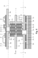
- En référence à la
figure 2 , le module électrique de puissance 1 comporte des supports 30 qui portent les composants de puissance de l'onduleur 2. - Les supports 30 sont assemblés entre eux de manière à ce que le module électrique de puissance 1 présente une forme extérieure générale tubulaire de section circulaire et d'axe longitudinal un axe X.
- Les supports 30 comprennent ici un premier support 30a, un deuxième support 30b, un troisième support 30c, un quatrième support 30d, un cinquième support 30e et un sixième support 30f.
- La
figure 2 est une vue en section du module électrique de puissance selon un plan parallèle à l'axe X et comprenant l'axe X. - Dans la vue de la
figure 2 , le premier support 30a présente la forme d'un T. Le premier support 30a comporte une première portion métallique 31 et une deuxième portion métallique 32 orientées l'une par rapport à l'autre d'un angle d'orientation supérieur à 0°. Ici, la première portion métallique 31 et la deuxième portion métallique 32 sont orthogonales entre elles. - Le deuxième support 30b, le troisième support 30c et le quatrième support 30d présentent la forme d'un angle droit. Le deuxième support 30b, le troisième support 30c et le quatrième support 30d comportent ainsi chacun une première portion métallique 31 et une deuxième portion métallique 32 orientées l'une par rapport à l'autre d'un angle d'orientation supérieur à 0°. Ici, la première portion métallique 31 et la deuxième portion métallique 32 sont orthogonales entre elles.
- Le cinquième support 30e présente la forme d'un F et comporte une première portion métallique 31, une deuxième portion métallique 32 et une troisième portion métallique 33.
- La deuxième portion métallique 32 du cinquième support 30e, la première portion métallique 31 et la troisième portion métallique 33 du cinquième support 30e sont orientées l'une par rapport à l'autre d'un angle d'orientation supérieur à 0°.
- En l'occurrence, la deuxième portion métallique 32 du cinquième support 30e est orthogonale à la première portion métallique 31 et à la troisième portion métallique 33 du cinquième support 30e.
- Le sixième support 30f présente une forme rectiligne et comporte une première portion métallique 31.
- Les premières portions métalliques 31 des supports 30 sont parallèles entre elles et à l'axe X.
- Les deuxièmes portions métalliques 32 des supports 30 sont parallèles entre elles et sont orthogonales à l'axe X.
- L'orientation entre elles des portions métalliques est ici réalisée au moment de la fabrication du module électrique de puissance.
- Cette orientation permet d'optimiser l'intégration du module électrique de puissance dans un boîtier ou dans un environnement quelconque. On peut en particulier orienter librement dans l'espace les accès aux entrées et aux sorties du module électrique de puissance et, notamment, aux connecteurs d'entrée et aux connecteurs de sortie situées sur les portions métalliques des supports.
- Le premier transistor 21a et la première diode 22a sont tous deux fixés à la deuxième portion métallique 32 du premier support 30a et à la deuxième portion métallique 32 du deuxième support 30b en étant positionnés entre lesdites deuxièmes portions métalliques 32.
- Une face du premier transistor 21a et une face de la première diode 22a sont fixées, par frittage d'un matériau de frittage comprenant une poudre d'argent, à la deuxième portion métallique 32 du premier support 30a.
- Le premier support 30a est ainsi connecté électriquement au drain du premier transistor 21a et à la cathode de la première diode 22a
- Une autre face du premier transistor 21a et une autre face de la première diode 22a sont fixées, par frittage du matériau de frittage, à la deuxième portion métallique 32 du deuxième support 30b.
- Le deuxième support 30b est ainsi connecté électriquement à une source du premier transistor 21a et à une anode de la première diode 22a.
- Le deuxième transistor 21b et la deuxième diode 22b sont fixés de la même manière aux deuxièmes portions métalliques 32 du deuxième support 30b et du troisième support 30c.
- Le deuxième support 30b est ainsi connecté électriquement à une source du deuxième transistor 21b et à une anode de la deuxième diode 22b. Le troisième support 30c est ainsi connecté électriquement à un drain du deuxième transistor 21b et à une cathode de la deuxième diode 22b.
- Le quatrième transistor 21d et la quatrième diode 22d sont fixés de la même manière aux deuxièmes portions métalliques 32 du troisième support 30c et du quatrième support 30d.
- Le troisième support 30c est ainsi connecté électriquement à un drain du quatrième transistor 21d et à une cathode de la quatrième diode 22d. Le quatrième support 30d est ainsi connecté électriquement à une source du quatrième transistor 21d et à une anode de la quatrième diode 22d.
- Le troisième transistor 21c et la troisième diode 22c sont fixés de la même manière aux deuxièmes portions métalliques 32 du quatrième support 30d et du cinquième support 30e.
- Le quatrième support 30d est ainsi connecté électriquement à une source du troisième transistor 21c et à une anode de la troisième diode 22c. Le cinquième support 30e est ainsi connecté électriquement à un drain du troisième transistor 21c et à une cathode de la troisième diode 22c.
- Le sixième transistor 21f et la sixième diode 22f sont fixés de la même manière aux deuxièmes portions métalliques 32 du troisième support 30c et du sixième support 30f.
- Le troisième support 30c est ainsi connecté électriquement à un drain du sixième transistor 21f et à une cathode de la sixième diode 22f. Le sixième support 30f est ainsi connecté électriquement à une source du sixième transistor 21f et à une anode de la sixième diode 21f.
- Le cinquième transistor 21e et la cinquième diode 22e sont fixés de la même manière aux deuxièmes portions métalliques 32 du cinquième support 30e et du sixième support 30f.
- Le cinquième support 30e est ainsi connecté électriquement à un drain du cinquième transistor 21e et à une cathode de la cinquième diode 22e. Le sixième support 30f est ainsi connecté électriquement à une source du cinquième transistor 21e et à une anode de la cinquième diode 22e.
- Les finitions des transistors 21 et des diodes 22, c'est à dire la métallisation de leurs contacts, peuvent comporter tout matériau métallique, et notamment les matériaux suivants : Ag, Au, Pd, Al, Cu, Ni, etc.
- Des courant électriques de puissance, provenant ou à destination des transistors 21, circulent dans les portions métalliques 32 des supports 30.
- Les courants électriques de puissance comprennent le courant électrique d'alimentation Ial, le premier courant de phase Ip1, le deuxième courant de phase Ip2 et le troisième courant de phase Ip3.
- Le premier support 30a est relié au conducteur d'alimentation positive 10, et le courant d'alimentation Ial circule dans la première portion métallique 31 et dans la deuxième portion métallique 32 du premier support 30a. Le drain du premier transistor 21a et la cathode de la première diode 22a sont donc portés à la tension d'alimentation continue positive.
- Le cinquième support 30e est relié au conducteur d'alimentation positive 10, et le courant d'alimentation Ial circule dans la première portion métallique 31 et dans la deuxième portion métallique 32 du cinquième support 30e. Le drain du troisième transistor 21c et du cinquième transistor 21e, et la cathode de la troisième diode 22c et de la cinquième diode 22e, sont donc portés à la tension d'alimentation continue positive.
- Le troisième support 30c est relié au conducteur d'alimentation négative 11, et le courant d'alimentation Ial circule dans la première portion métallique 31 et dans la deuxième portion métallique 32 du troisième support 30c. Les sources du deuxième transistor 21b, du quatrième transistor 21d et du sixième transistor 21f, et les anodes de la deuxième diode 22b, de la quatrième diode 22d et de la sixième diode 22f sont donc portées à la tension d'alimentation continue négative.
- Le premier courant de phase Ip1, le deuxième courant de phase Ip2 et le troisième courant de phase Ip3 circulent respectivement dans le deuxième support 30b, le quatrième support 30d et le sixième support 30f, à destination respectivement de la première phase Ph1, de la deuxième phase Ph2 et de la troisième phase Ph3 du moteur 3.
- Le deuxième support 30b, le quatrième support 30d et le sixième support 30f sont recouverts au moins partiellement de céramique ferromagnétique 34. La céramique ferromagnétique 34 forme, sur ces supports, des filtres de parasites à haute fréquence. La céramique ferromagnétique est appliquée par la technique de la « fabrication additive », ou via une technologie de 3D-MID (pour 3D-Mechatronic Integrated Devices).
- L'épaisseur Es d'au moins un support 30 est telle que :

- En référence à la
figure 3 , on note que le premier support 30a, le troisième support 30c, le cinquième support 30e et le sixième support 30f portent aussi des pistes 35 sur lesquelles circulent les courants électriques de commande Ic à destination des grilles des transistors 21. - Chaque transistor 21 présente une première face 36 comprenant un premier élément conducteur relié au drain du transistor 21 et un deuxième élément conducteur relié à la grille du transistor 21, et une deuxième face 37 comprenant un troisième élément conducteur relié à la source du transistor 21.
- Comme on l'a vu plus tôt, le matériau de frittage 38 est disposé sur le premier élément conducteur, le deuxième élément conducteur et le troisième élément conducteur.
- Entre le matériau de frittage 38 disposé sur le deuxième élément conducteur et la portion métallique 32, on trouve une piste 35 et une couche isolante 39. La couche isolante 39 isole la piste 35 de la portion métallique 32 du support 30 sur laquelle circule le courant de puissance (courant d'alimentation ou courant de phase).
- La piste 35 comporte ici un matériau conducteur comprenant de l'argent et un oxyde. Le matériau conducteur est dispersé dans un liant sérigraphiable.
- La couche isolante 39 comporte ici un matériau isolant inorganique de type fritte de verre. Le matériau isolant inorganique est dispersé dans un liant sérigraphiable.
- Le module électrique de puissance 1 permet une dissipation de chaleur via un transfert d'énergie isotrope entre les transistors 21 au travers du substrat constitué par les supports 30.
- La dissipation de chaleur est une dissipation tri-modale simultanée, par conduction, convexion et radiation. La dissipation de chaleur peut être paramétrable, en utilisant un élément conducteur thermique pour fabriquer les supports 30, dont les contours favorisent une bonne émissivité. On utilisera avantageusement la technique de « fabrication additive » pour former ces contours.
- On note par ailleurs que des composants électriques sont disposés sur la surface extérieure du module électrique de puissance 1. Les composants électriques comprennent la capacité de liaison 6, ainsi qu'un composant 40 et une puce 41. La puce 41 est reliée via un « câblage par fil » 42 (ou wire bonding) à une piste 43. Le substrat 44 sur lequel sont montés ces composants électriques est cette fois un substrat traditionnel.
- En référence à la
figure 4 , l'agencement des supports 30 est basé sur une cellule de puissance générique 45 qui comporte le premier support 30a, le deuxième support 30b et le troisième support 30c. On note que, sur lafigure 4 , le deuxième support 30b et le troisième support 30c sont munis d'ailettes de dissipation de chaleur 46 qui favorisent le refroidissement du module électrique de puissance. - Cette cellule générique 45, qui forme un bras de pont 16 comprenant un premier transistor 48a et un deuxième transistor 48b, peut être dupliquée autant de fois que nécessaire pour créer une fonction de puissance quelconque.
- On note que le premier transistor 48a et le deuxième transistor 48b sont positionnés de part et d'autre du deuxième support 30b en étant superposés et centrés l'un par rapport à l'autre. Une distance d entre un premier axe Za perpendiculaire à une face du premier transistor 48a et passant par un centre de ladite face, et entre un deuxième axe Zb perpendiculaire à une face du deuxième transistor 48b et passant par un centre de ladite face, est inférieure ou égale au tiers d'une diagonale de la face ayant une surface la plus importante.
- Cette cellule générique 45 peut être configurée différemment, c'est à dire que les supports 30 peuvent présenter des formes différentes, ou être disposés différemment les uns par rapport aux autres.
- Une pluralité de cellules génériques 45 de formes diverses peut être utilisée pour réaliser un module électrique de puissance 1 conforme à tout type d'exigence d'intégration.
- En référence à la
figure 5 , le module électrique de puissance 1 comporte un capot 50 étanche, fabriqué en plastique, de forme tubulaire. Le capot 50 est ici fixé au deuxième support 30b, au troisième support 30c, au quatrième support 30d et au cinquième support 30e. - Les supports 30 et le capot 50 définissent un canal 51 à l'intérieur du module électrique de puissance 1.
- Un fluide de refroidissement Fr, par exemple un gaz ou un liquide caloporteur, circule ainsi dans le canal 51 défini par les supports 30 et par le capot 50. Le fluide traverse le deuxième support 30b, le troisième support 30c et le quatrième support par des orifices 52 pratiqués dans ces supports. La circulation du liquide de refroidissement dans le canal 51 permet de refroidir très efficacement le module électrique de puissance 1.
- Le fluide de refroidissement assure une isolation du module électrique de puissance. La vitesse de circulation du fluide de refroidissement est ici d'environ 0,001m/s. La vitesse de circulation garantit l'absence d'apparition de décharges partielles lors des commutations électriques des interrupteurs formés par les transistors 21.
- Les contours des supports 30 sont dimensionnés pour favoriser une grande surface d'échange avec le fluide de refroidissement.
- Avantageusement, les supports 30 et, en particulier, les premières portions métalliques 31 et les deuxièmes portions métalliques 32, sont fabriqués en utilisant la technique de fabrication additive. Le matériau utilisé est par exemple l'aluminium. On peut ainsi définir des canaux de refroidissement à l'intérieur des premières portions métalliques 31 et des deuxièmes portions métalliques 32 des supports 30.
- La performance thermique obtenue est inversement proportionnelle au diamètre des canaux de refroidissement, mais le bilan des pertes de charge hydraulique est lui proportionnel au diamètre des canaux de refroidissement.
- Pour des diamètres des canaux de refroidissement compris entre 10µm et 800µm, on parle d'échangeurs de chaleur à micro-canaux. Pour des diamètres des canaux de refroidissement compris entre 1mm et 10mm, on parle d'échangeurs de chaleur à mini-canaux. Pour des diamètres des canaux de refroidissement supérieurs à 10mm, on parle de plaque froide.
- Au cours de la fabrication du module électrique de puissance, un premier isolant est tout d'abord appliqué par sérigraphie en couche épaisse sur chaque face des supports 30 portant les transistors 21. Puis, les composants sont montés sur les supports 30, et le module électrique de puissance est assemblé. Un deuxième isolant est alors déposé par un procédé plasma, par un dépôt en phase vapeur, par évaporation ou par laminage. On forme ainsi un revêtement sans fissure et sans bulle, et qui présente des variations d'épaisseur inférieures à 1µm. Ce revêtement recouvre et isole toutes les surfaces internes et externes du module électrique de puissance.
- Le module électrique de puissance est enfin recouvert par une résine ou intégré dans un emballage de protection. On préserve ainsi l'isolement électrique de contraintes mécaniques extérieures susceptibles de provoquer des rayures, des chocs, des écrasements, etc. Les connecteurs d'entrée et de sortie, permettant de relier le module électrique de puissance à un moteur ou à un autre équipement, sont eux laissés libres.
- Bien entendu, l'invention n'est pas limitée au mode de réalisation décrit mais englobe toute variante entrant dans le champ de l'invention telle que définie par les revendications.
- Le module électrique de puissance décrit ici comprend un onduleur, mais l'invention peut bien sûr s'appliquer à tout type de module de puissance électrique mettant en œuvre tout type de fonction de puissance.
- Le nombre de bras de pont pourrait bien sûr être différent, tout comme les composants de puissance utilisés.
- Bien que l'on ait indiqué que les composants sont fixés par frittage aux supports, un moyen de fixation différent pourrait être utilisé, par exemple le brasage ou le collage.
- On a décrit ici que les premières portions métalliques 31 et les deuxièmes portions métalliques 32 sont orthogonales entre elles. Une première portion métalliques et une deuxième portion métallique orientées d'au moins un support pourraient cependant être orientées l'une par rapport à l'autre d'un angle d'orientation différent, supérieur à 0°.
- On a aussi indiqué que l'orientation des portions métalliques est réalisée au moment de la fabrication du module électrique de puissance. On peut aussi prévoir que le ou les angles d'orientation soient réglés au moment de l'intégration du module électrique de puissance dans un boîtier contenant ledit module électrique de puissance. Les portions métalliques sont alors fixées entre elles par des moyens de fixation permettant d'effectuer le réglage de l'angle d'orientation.
Claims (17)
- Module électrique de puissance comportant des composants de puissance (21, 22) et des supports (30) comprenant chacun au moins une portion métallique (31, 32), les portions métalliques des supports formant un substrat du module électrique de puissance (1), , chaque composant de puissance étant fixé à deux portions métalliques de deux supports distincts en étant positionné entre lesdites deux portions métalliques, le module électrique de puissance étant agencé de sorte que des courants électriques de puissance provenant ou à destination des composants de puissance circulent dans les portions métalliques des supports, au moins un support 30c, 30e) comprenant deux portions métalliques orientées l'une par rapport à l'autre d'un angle d'orientation supérieur à 0°, caractérisé en ce que les deux portions métalliques orientées sont orthogonales entre elles, et en ce qu' un composant de puissance distinct est fixé sur chacune desdites deux portions métalliques orientées.
- Module électrique de puissance selon la revendication 1, dans lequel les deux portions métalliques orientées sont agencées de sorte que l'angle d'orientation peut être réglé au moment de l'intégration du module électrique de puissance dans un boîtier.
- Module électrique de puissance selon la revendication 1, dans lequel les composants de puissance comprennent des composants pilotables (21), le module électrique de puissance comprenant des pistes (35) dans lesquelles circulent des courants électriques de commande (Ic) à destination des composants pilotables, chaque piste étant positionnée entre deux portions métalliques de deux supports distincts, chaque piste étant isolée d'une portion métallique (32) d'un support (30) par une couche isolante (39).
- Module électrique de puissance selon la revendication 3, dans lequel au moins l'une des pistes (35) comporte un matériau conducteur comprenant de l'argent et un oxyde, le matériau conducteur étant dispersé dans un liant sérigraphiable.
- Module électrique de puissance selon la revendication 3, dans lequel au moins l'une des couches isolantes (39) comporte un matériau isolant inorganique de type fritte de verre, le matériau isolant inorganique étant dispersé dans un liant sérigraphiable.
- Module électrique de puissance selon la revendication 1, dans lequel une face de chaque composant de puissance (21, 22) est fixée à une portion métallique d'un support par frittage.
- Module électrique de puissance selon la revendication 1, dans lequel les supports sont partiellement recouverts de céramique ferromagnétique (34) formant des filtres passe-bas.
- Module électrique de puissance selon la revendication 1, dans lequel les supports délimitent un canal (51) à l'intérieur du module électrique de puissance, le module électrique de puissance étant agencé de sorte qu'un fluide circule dans le canal (51) pour refroidir le module électrique de puissance.
- Module électrique de puissance selon la revendication 8, comprenant en outre un capot (50) étanche en plastique qui délimite aussi le canal, le capot étant fixé à des supports.
- Module électrique de puissance selon la revendication 1, dans lequel les supports (30) sont fabriqués en utilisant une technique de fabrication additive.
- Module électrique de puissance selon la revendication 1, dans lequel des canaux de refroidissement sont définis à l'intérieur des supports (30).
- Module électrique de puissance selon la revendication 1, comprenant au moins trois supports (30).
- Module électrique de puissance selon la revendication 1, dans lequel une épaisseur Es d'un support (30) est telle que :

- Module électrique de puissance selon la revendication 1, les composants de puissance comprenant deux transistors (21) et deux diodes (22) formant un bras de pont (16), le module électrique de puissance comprenant un premier support (30a) dans lequel circule un courant électrique d'alimentation sous une tension d'alimentation continue positive, un deuxième support (30b) dans lequel circule un courant de sortie alternatif, et un troisième support (30c) dans lequel circule un courant électrique d'alimentation sous une tension d'alimentation continue négative.
- Module électrique de puissance selon la revendication 14, comprenant un premier transistor (48a) et un deuxième transistor (48b) d'un même bras de pont, le premier transistor (48a) et le deuxième transistor (48b) étant positionnés de part et d'autre d'un même support (30b) en étant superposés et centrés l'un par rapport à l'autre.
- Module électrique de puissance selon la revendication 15, dans lequel une distance (d) entre un premier axe (Za) perpendiculaire à une face du premier transistor (48a) et passant par un centre de ladite face, et entre un deuxième axe (Zb) perpendiculaire à une face du deuxième transistor (48b) et passant par un centre de ladite face, est inférieure ou égale au tiers d'une longueur d'une diagonale de la face ayant une surface la plus importante.
- Actionneur électromécanique comportant un module électrique de puissance selon la revendication 14 et un moteur électrique (3).
Applications Claiming Priority (2)
| Application Number | Priority Date | Filing Date | Title |
|---|---|---|---|
| FR1761015A FR3074011B1 (fr) | 2017-11-21 | 2017-11-21 | Module electrique de puissance |
| PCT/EP2018/081510 WO2019101634A1 (fr) | 2017-11-21 | 2018-11-16 | Module électrique de puissance |
Publications (2)
| Publication Number | Publication Date |
|---|---|
| EP3714667A1 EP3714667A1 (fr) | 2020-09-30 |
| EP3714667B1 true EP3714667B1 (fr) | 2025-05-14 |
Family
ID=61655867
Family Applications (1)
| Application Number | Title | Priority Date | Filing Date |
|---|---|---|---|
| EP18803422.7A Active EP3714667B1 (fr) | 2017-11-21 | 2018-11-16 | Module électrique de puissance |
Country Status (5)
| Country | Link |
|---|---|
| US (1) | US11444543B2 (fr) |
| EP (1) | EP3714667B1 (fr) |
| CN (1) | CN111373850B (fr) |
| FR (1) | FR3074011B1 (fr) |
| WO (1) | WO2019101634A1 (fr) |
Families Citing this family (10)
| Publication number | Priority date | Publication date | Assignee | Title |
|---|---|---|---|---|
| DE102019202777A1 (de) * | 2018-12-18 | 2020-06-18 | Robert Bosch Gmbh | Niederinduktive Verbindungsvorrichtung |
| CN217608150U (zh) * | 2019-06-24 | 2022-10-18 | 米沃奇电动工具公司 | 电动工具 |
| DE102019132899A1 (de) * | 2019-12-03 | 2021-08-19 | Danfoss Silicon Power Gmbh | Leistungsmodul |
| FR3114725B1 (fr) * | 2020-09-28 | 2023-11-03 | Inst Polytechnique Grenoble | Système électronique de puissance |
| FR3121278A1 (fr) | 2021-03-26 | 2022-09-30 | Safran Electronics & Defense | Procédé pour assembler un composant électronique à un substrat par pressage |
| DE102022208416B4 (de) * | 2022-08-12 | 2025-10-30 | Schaeffler Technologies AG & Co. KG | Stromschienenanordnung und Schaltanordnung |
| FR3144483B1 (fr) | 2022-12-22 | 2024-12-20 | Safran Electronics & Defense | Module électronique de puissance multi-étages et hermétique |
| FR3144399B1 (fr) | 2022-12-22 | 2026-03-13 | Safran Electronics & Defense | Module électronique de puissance multi-étages |
| IT202200026742A1 (it) * | 2022-12-23 | 2024-06-23 | Friem S P A | Apparato convertitore elettronico di potenza comprendente moduli convertitori tra loro sovrapposti ed una unità di raffreddamento a ventilazione forzata |
| DK181881B1 (en) * | 2023-03-28 | 2025-03-03 | Kk Wind Solutions As | Temperature regulation of a high-power electrical system |
Citations (1)
| Publication number | Priority date | Publication date | Assignee | Title |
|---|---|---|---|---|
| US20130069108A1 (en) * | 2011-09-16 | 2013-03-21 | Samsung Electro-Mechanics Co., Ltd. | Power semiconductor module |
Family Cites Families (33)
| Publication number | Priority date | Publication date | Assignee | Title |
|---|---|---|---|---|
| US5063475A (en) * | 1990-03-19 | 1991-11-05 | International Business Machines Corporation | Multileveled electronic assembly with cooling means |
| DE29504352U1 (de) * | 1995-03-14 | 1995-08-03 | eupec Europäische Gesellschaft für Leistungshalbleiter mbH + Co.KG, 59581 Warstein | Halbleiteranordnung mit Spannvorrichtung für scheibenförmige Leistungs-Halbleiterbauelemente |
| JPH09307038A (ja) * | 1996-05-14 | 1997-11-28 | Fuji Electric Co Ltd | 電力変換装置の冷却装置 |
| FR2765067B1 (fr) * | 1997-06-19 | 1999-07-16 | Alsthom Cge Alcatel | Module d'electronique de puissance et un dispositif d'electronique de puissance pourvu de tels modules |
| US7507903B2 (en) * | 1999-03-30 | 2009-03-24 | Daniel Luch | Substrate and collector grid structures for integrated series connected photovoltaic arrays and process of manufacture of such arrays |
| CN1292325C (zh) * | 1999-04-08 | 2006-12-27 | 富准精密工业(深圳)有限公司 | 形成散热鳍片的方法、机器及其成品 |
| JP2001237581A (ja) * | 2000-02-24 | 2001-08-31 | Toshiba Corp | 発熱素子の冷却装置 |
| JP3847676B2 (ja) * | 2002-07-15 | 2006-11-22 | 三菱電機株式会社 | パワー半導体装置 |
| US6822850B2 (en) * | 2002-09-27 | 2004-11-23 | Rockwell Automation Technologies, Inc. | Laminated bus bar for use with a power conversion configuration |
| TW200741470A (en) * | 2006-04-19 | 2007-11-01 | Tyan Computer Corp | Multi-processor system and tubelike computer architecture thereof |
| KR101203466B1 (ko) * | 2006-04-20 | 2012-11-21 | 페어차일드코리아반도체 주식회사 | 전력 시스템 모듈 및 그 제조 방법 |
| JP4719187B2 (ja) * | 2007-06-15 | 2011-07-06 | トヨタ自動車株式会社 | 半導体素子の冷却構造 |
| FR2929482B1 (fr) * | 2008-04-01 | 2013-07-05 | Thales Sa | Calculateur a l'agencement simplifie, destine a l'aeronautique |
| FR2951019B1 (fr) * | 2009-10-07 | 2012-06-08 | Valeo Etudes Electroniques | Module de puissance pour vehicule automobile |
| JP5115632B2 (ja) * | 2010-06-30 | 2013-01-09 | 株式会社デンソー | 半導体装置 |
| JP2012138473A (ja) * | 2010-12-27 | 2012-07-19 | Zycube:Kk | 半導体デバイス・電子部品の実装構造 |
| JP5807220B2 (ja) * | 2010-12-30 | 2015-11-10 | 株式会社ザイキューブ | インターポーザ及びそれを用いた半導体モジュール |
| CN103765751B (zh) * | 2011-09-02 | 2016-08-17 | 富士电机株式会社 | 电力变换装置 |
| US9048338B2 (en) * | 2011-11-04 | 2015-06-02 | Infineon Technologies Ag | Device including two power semiconductor chips and manufacturing thereof |
| WO2013088642A1 (fr) * | 2011-12-13 | 2013-06-20 | 富士電機株式会社 | Dispositif de conversion de puissance |
| CN102543988B (zh) * | 2012-03-02 | 2014-06-25 | 大连理工大学 | 金属支撑垂直结构无荧光粉白光led的制备方法 |
| CN103368359B (zh) * | 2012-04-11 | 2016-04-13 | 台达电子工业股份有限公司 | 变流器功率单元及其母线排 |
| US9521766B2 (en) * | 2012-06-27 | 2016-12-13 | CommScope Connectivity Belgium BVBA | High density telecommunications systems with cable management and heat dissipation features |
| JP5716972B2 (ja) * | 2013-02-05 | 2015-05-13 | 株式会社デンソー | 電子部品の放熱構造およびその製造方法 |
| US9215833B2 (en) * | 2013-03-15 | 2015-12-15 | Apple Inc. | Electronic device with heat dissipating electromagnetic interference shielding structures |
| JP5821890B2 (ja) * | 2013-04-17 | 2015-11-24 | トヨタ自動車株式会社 | 電力変換装置 |
| DE102013207507B3 (de) * | 2013-04-25 | 2014-07-24 | Conti Temic Microelectronic Gmbh | Leistungsmodul, Stromrichter und Antriebsanordnung mit einem Leistungsmodul |
| US9519319B2 (en) * | 2014-03-14 | 2016-12-13 | Sandisk Technologies Llc | Self-supporting thermal tube structure for electronic assemblies |
| US9148946B1 (en) * | 2014-03-28 | 2015-09-29 | Deere & Company | Electronic assembly for an inverter |
| US9531170B2 (en) * | 2014-07-22 | 2016-12-27 | Hamilton Sundstrand Corporation | Interconnects for electrical power distribution systems |
| CN105611804B (zh) * | 2015-12-30 | 2019-02-26 | 杭州华为数字技术有限公司 | 导热垫、散热器及电子产品 |
| CN206024223U (zh) * | 2016-05-26 | 2017-03-15 | 东莞联桥电子有限公司 | 一种可调式防呆散热电路板 |
| JP6654609B2 (ja) * | 2017-10-10 | 2020-02-26 | 本田技研工業株式会社 | 電力変換装置 |
-
2017
- 2017-11-21 FR FR1761015A patent/FR3074011B1/fr active Active
-
2018
- 2018-11-16 US US16/765,412 patent/US11444543B2/en active Active
- 2018-11-16 CN CN201880075479.1A patent/CN111373850B/zh active Active
- 2018-11-16 WO PCT/EP2018/081510 patent/WO2019101634A1/fr not_active Ceased
- 2018-11-16 EP EP18803422.7A patent/EP3714667B1/fr active Active
Patent Citations (1)
| Publication number | Priority date | Publication date | Assignee | Title |
|---|---|---|---|---|
| US20130069108A1 (en) * | 2011-09-16 | 2013-03-21 | Samsung Electro-Mechanics Co., Ltd. | Power semiconductor module |
Also Published As
| Publication number | Publication date |
|---|---|
| CN111373850A (zh) | 2020-07-03 |
| US11444543B2 (en) | 2022-09-13 |
| US20200336078A1 (en) | 2020-10-22 |
| FR3074011B1 (fr) | 2019-12-20 |
| FR3074011A1 (fr) | 2019-05-24 |
| EP3714667A1 (fr) | 2020-09-30 |
| CN111373850B (zh) | 2022-07-22 |
| WO2019101634A1 (fr) | 2019-05-31 |
Similar Documents
| Publication | Publication Date | Title |
|---|---|---|
| EP3714667B1 (fr) | Module électrique de puissance | |
| CA2115303C (fr) | Dispositif de refroidissement de composants electriques de puissance | |
| EP3154082B1 (fr) | Structure dbc amelioree dotee d'un support integrant un materiau a changement de phase | |
| FR2570169A1 (fr) | Perfectionnements apportes aux modules thermo-electriques a plusieurs thermo-elements pour installation thermo-electrique, et installation thermo-electrique comportant de tels modules thermo-electriques | |
| FR2829874A1 (fr) | Systeme a semi-conducteur a boitier et enveloppe | |
| FR3016266A1 (fr) | Dispositif electronique de puissance a refroidissement ameliore | |
| EP3714669B1 (fr) | Module electronique de puissance | |
| EP3494594B1 (fr) | Procédé de fabrication d'un module de puissance tridimensionnel | |
| WO2018091852A1 (fr) | Circuit intégré forme de deux puces connectées en série | |
| EP3052909B1 (fr) | Circuit imprime flexible a faible emissivite | |
| EP3241411B1 (fr) | Boitier hyperfrequence a encombrement reduit en surface et montage d'un tel boitier sur un circuit | |
| EP3035018B1 (fr) | Capteur differentiel de temperature | |
| FR2984602A1 (fr) | Dispositif de connexion electrique multicouche de materiaux supraconducteurs entre deux circuits | |
| FR2669177A1 (fr) | Procede pour realiser l'assemblage reversible d'un circuit electronique de lecture et/ou d'exploitation et d'un support conducteur ou non de l'electricite. | |
| WO2007085774A1 (fr) | Module electronique et procede d'assemblage d'un tel module | |
| EP2525402A1 (fr) | Dispositif d'isolation électrique à tension de claquage ameliorée | |
| EP3242322B1 (fr) | Dispositif electronique de puissance a structure d'interconnexion electrique plane | |
| FR3112241A1 (fr) | Dispositif de refroidissement mis en œuvre dans une application d’électronique de puissance | |
| FR3060941B1 (fr) | Module de puissance refroidi par caloduc et procede de fabrication d'un tel module | |
| EP1032114B1 (fr) | Module électrique pour alternateur de véhicule, notamment automobile, et assemblage comportant un tel alternateur et un tel module | |
| EP4062447B1 (fr) | Cadre metallique conducteur pour module électronique de puissance et procede de fabrication associe | |
| WO2018020189A2 (fr) | Module électronique de puissance d'un aéronef et procédé de fabrication associé | |
| WO2025180784A1 (fr) | Module de commutation electrique et dispositif de commutation comprenant un tel module | |
| WO2024200853A1 (fr) | Module d'éclairage comprenant un dispositif de refroidissement produisant un flux d'air par ionisation de l'air | |
| WO2024134097A1 (fr) | Module électronique de puissance multi-étages et hermétique |
Legal Events
| Date | Code | Title | Description |
|---|---|---|---|
| STAA | Information on the status of an ep patent application or granted ep patent |
Free format text: STATUS: UNKNOWN |
|
| STAA | Information on the status of an ep patent application or granted ep patent |
Free format text: STATUS: THE INTERNATIONAL PUBLICATION HAS BEEN MADE |
|
| PUAI | Public reference made under article 153(3) epc to a published international application that has entered the european phase |
Free format text: ORIGINAL CODE: 0009012 |
|
| STAA | Information on the status of an ep patent application or granted ep patent |
Free format text: STATUS: REQUEST FOR EXAMINATION WAS MADE |
|
| 17P | Request for examination filed |
Effective date: 20200520 |
|
| AK | Designated contracting states |
Kind code of ref document: A1 Designated state(s): AL AT BE BG CH CY CZ DE DK EE ES FI FR GB GR HR HU IE IS IT LI LT LU LV MC MK MT NL NO PL PT RO RS SE SI SK SM TR |
|
| AX | Request for extension of the european patent |
Extension state: BA ME |
|
| DAV | Request for validation of the european patent (deleted) | ||
| DAX | Request for extension of the european patent (deleted) | ||
| STAA | Information on the status of an ep patent application or granted ep patent |
Free format text: STATUS: EXAMINATION IS IN PROGRESS |
|
| 17Q | First examination report despatched |
Effective date: 20220414 |
|
| GRAP | Despatch of communication of intention to grant a patent |
Free format text: ORIGINAL CODE: EPIDOSNIGR1 |
|
| STAA | Information on the status of an ep patent application or granted ep patent |
Free format text: STATUS: GRANT OF PATENT IS INTENDED |
|
| INTG | Intention to grant announced |
Effective date: 20241212 |
|
| GRAS | Grant fee paid |
Free format text: ORIGINAL CODE: EPIDOSNIGR3 |
|
| GRAA | (expected) grant |
Free format text: ORIGINAL CODE: 0009210 |
|
| STAA | Information on the status of an ep patent application or granted ep patent |
Free format text: STATUS: THE PATENT HAS BEEN GRANTED |
|
| AK | Designated contracting states |
Kind code of ref document: B1 Designated state(s): AL AT BE BG CH CY CZ DE DK EE ES FI FR GB GR HR HU IE IS IT LI LT LU LV MC MK MT NL NO PL PT RO RS SE SI SK SM TR |
|
| REG | Reference to a national code |
Ref country code: GB Ref legal event code: FG4D Free format text: NOT ENGLISH |
|
| RIN1 | Information on inventor provided before grant (corrected) |
Inventor name: SRIDI-CONVERS,NAWRES Inventor name: BAILLY, ERIC Inventor name: RIOU, JEAN-CHRISTOPHE |
|
| REG | Reference to a national code |
Ref country code: CH Ref legal event code: EP |
|
| REG | Reference to a national code |
Ref country code: DE Ref legal event code: R096 Ref document number: 602018081952 Country of ref document: DE |
|
| REG | Reference to a national code |
Ref country code: IE Ref legal event code: FG4D Free format text: LANGUAGE OF EP DOCUMENT: FRENCH |
|
| REG | Reference to a national code |
Ref country code: NL Ref legal event code: MP Effective date: 20250514 |
|
| PG25 | Lapsed in a contracting state [announced via postgrant information from national office to epo] |
Ref country code: PT Free format text: LAPSE BECAUSE OF FAILURE TO SUBMIT A TRANSLATION OF THE DESCRIPTION OR TO PAY THE FEE WITHIN THE PRESCRIBED TIME-LIMIT Effective date: 20250915 Ref country code: FI Free format text: LAPSE BECAUSE OF FAILURE TO SUBMIT A TRANSLATION OF THE DESCRIPTION OR TO PAY THE FEE WITHIN THE PRESCRIBED TIME-LIMIT Effective date: 20250514 Ref country code: ES Free format text: LAPSE BECAUSE OF FAILURE TO SUBMIT A TRANSLATION OF THE DESCRIPTION OR TO PAY THE FEE WITHIN THE PRESCRIBED TIME-LIMIT Effective date: 20250514 |
|
| REG | Reference to a national code |
Ref country code: LT Ref legal event code: MG9D |
|
| PG25 | Lapsed in a contracting state [announced via postgrant information from national office to epo] |
Ref country code: NO Free format text: LAPSE BECAUSE OF FAILURE TO SUBMIT A TRANSLATION OF THE DESCRIPTION OR TO PAY THE FEE WITHIN THE PRESCRIBED TIME-LIMIT Effective date: 20250814 Ref country code: GR Free format text: LAPSE BECAUSE OF FAILURE TO SUBMIT A TRANSLATION OF THE DESCRIPTION OR TO PAY THE FEE WITHIN THE PRESCRIBED TIME-LIMIT Effective date: 20250815 |
|
| PG25 | Lapsed in a contracting state [announced via postgrant information from national office to epo] |
Ref country code: PL Free format text: LAPSE BECAUSE OF FAILURE TO SUBMIT A TRANSLATION OF THE DESCRIPTION OR TO PAY THE FEE WITHIN THE PRESCRIBED TIME-LIMIT Effective date: 20250514 Ref country code: NL Free format text: LAPSE BECAUSE OF FAILURE TO SUBMIT A TRANSLATION OF THE DESCRIPTION OR TO PAY THE FEE WITHIN THE PRESCRIBED TIME-LIMIT Effective date: 20250514 |
|
| REG | Reference to a national code |
Ref country code: AT Ref legal event code: MK05 Ref document number: 1795913 Country of ref document: AT Kind code of ref document: T Effective date: 20250514 |
|
| PG25 | Lapsed in a contracting state [announced via postgrant information from national office to epo] |
Ref country code: BG Free format text: LAPSE BECAUSE OF FAILURE TO SUBMIT A TRANSLATION OF THE DESCRIPTION OR TO PAY THE FEE WITHIN THE PRESCRIBED TIME-LIMIT Effective date: 20250514 |
|
| PG25 | Lapsed in a contracting state [announced via postgrant information from national office to epo] |
Ref country code: HR Free format text: LAPSE BECAUSE OF FAILURE TO SUBMIT A TRANSLATION OF THE DESCRIPTION OR TO PAY THE FEE WITHIN THE PRESCRIBED TIME-LIMIT Effective date: 20250514 |
|
| PG25 | Lapsed in a contracting state [announced via postgrant information from national office to epo] |
Ref country code: AT Free format text: LAPSE BECAUSE OF FAILURE TO SUBMIT A TRANSLATION OF THE DESCRIPTION OR TO PAY THE FEE WITHIN THE PRESCRIBED TIME-LIMIT Effective date: 20250514 |
|
| PG25 | Lapsed in a contracting state [announced via postgrant information from national office to epo] |
Ref country code: RS Free format text: LAPSE BECAUSE OF FAILURE TO SUBMIT A TRANSLATION OF THE DESCRIPTION OR TO PAY THE FEE WITHIN THE PRESCRIBED TIME-LIMIT Effective date: 20250814 |
|
| PG25 | Lapsed in a contracting state [announced via postgrant information from national office to epo] |
Ref country code: IS Free format text: LAPSE BECAUSE OF FAILURE TO SUBMIT A TRANSLATION OF THE DESCRIPTION OR TO PAY THE FEE WITHIN THE PRESCRIBED TIME-LIMIT Effective date: 20250914 |
|
| PG25 | Lapsed in a contracting state [announced via postgrant information from national office to epo] |
Ref country code: LV Free format text: LAPSE BECAUSE OF FAILURE TO SUBMIT A TRANSLATION OF THE DESCRIPTION OR TO PAY THE FEE WITHIN THE PRESCRIBED TIME-LIMIT Effective date: 20250514 |
|
| PG25 | Lapsed in a contracting state [announced via postgrant information from national office to epo] |
Ref country code: DK Free format text: LAPSE BECAUSE OF FAILURE TO SUBMIT A TRANSLATION OF THE DESCRIPTION OR TO PAY THE FEE WITHIN THE PRESCRIBED TIME-LIMIT Effective date: 20250514 Ref country code: SM Free format text: LAPSE BECAUSE OF FAILURE TO SUBMIT A TRANSLATION OF THE DESCRIPTION OR TO PAY THE FEE WITHIN THE PRESCRIBED TIME-LIMIT Effective date: 20250514 |
|
| PGFP | Annual fee paid to national office [announced via postgrant information from national office to epo] |
Ref country code: FR Payment date: 20251125 Year of fee payment: 8 |
|
| PG25 | Lapsed in a contracting state [announced via postgrant information from national office to epo] |
Ref country code: CZ Free format text: LAPSE BECAUSE OF FAILURE TO SUBMIT A TRANSLATION OF THE DESCRIPTION OR TO PAY THE FEE WITHIN THE PRESCRIBED TIME-LIMIT Effective date: 20250514 |
|
| PG25 | Lapsed in a contracting state [announced via postgrant information from national office to epo] |
Ref country code: EE Free format text: LAPSE BECAUSE OF FAILURE TO SUBMIT A TRANSLATION OF THE DESCRIPTION OR TO PAY THE FEE WITHIN THE PRESCRIBED TIME-LIMIT Effective date: 20250514 |
|
| PG25 | Lapsed in a contracting state [announced via postgrant information from national office to epo] |
Ref country code: SK Free format text: LAPSE BECAUSE OF FAILURE TO SUBMIT A TRANSLATION OF THE DESCRIPTION OR TO PAY THE FEE WITHIN THE PRESCRIBED TIME-LIMIT Effective date: 20250514 Ref country code: RO Free format text: LAPSE BECAUSE OF FAILURE TO SUBMIT A TRANSLATION OF THE DESCRIPTION OR TO PAY THE FEE WITHIN THE PRESCRIBED TIME-LIMIT Effective date: 20250514 |
|
| PG25 | Lapsed in a contracting state [announced via postgrant information from national office to epo] |
Ref country code: IT Free format text: LAPSE BECAUSE OF FAILURE TO SUBMIT A TRANSLATION OF THE DESCRIPTION OR TO PAY THE FEE WITHIN THE PRESCRIBED TIME-LIMIT Effective date: 20250514 |
|
| REG | Reference to a national code |
Ref country code: DE Ref legal event code: R097 Ref document number: 602018081952 Country of ref document: DE |
|
| PLBE | No opposition filed within time limit |
Free format text: ORIGINAL CODE: 0009261 |
|
| STAA | Information on the status of an ep patent application or granted ep patent |
Free format text: STATUS: NO OPPOSITION FILED WITHIN TIME LIMIT |
|
| REG | Reference to a national code |
Ref country code: CH Ref legal event code: L10 Free format text: ST27 STATUS EVENT CODE: U-0-0-L10-L00 (AS PROVIDED BY THE NATIONAL OFFICE) Effective date: 20260325 |
|
| 26N | No opposition filed |
Effective date: 20260217 |