EP3714751B1 - Papierrollen-abwickelvorrichtung und führungshülse für papierrolle - Google Patents
Papierrollen-abwickelvorrichtung und führungshülse für papierrolle Download PDFInfo
- Publication number
- EP3714751B1 EP3714751B1 EP20166879.5A EP20166879A EP3714751B1 EP 3714751 B1 EP3714751 B1 EP 3714751B1 EP 20166879 A EP20166879 A EP 20166879A EP 3714751 B1 EP3714751 B1 EP 3714751B1
- Authority
- EP
- European Patent Office
- Prior art keywords
- foolproof
- roll
- unwinder
- endpiece
- support
- Prior art date
- Legal status (The legal status is an assumption and is not a legal conclusion. Google has not performed a legal analysis and makes no representation as to the accuracy of the status listed.)
- Active
Links
Images


Classifications
-
- A—HUMAN NECESSITIES
- A47—FURNITURE; DOMESTIC ARTICLES OR APPLIANCES; COFFEE MILLS; SPICE MILLS; SUCTION CLEANERS IN GENERAL
- A47K—SANITARY EQUIPMENT; ACCESSORIES THEREFOR, e.g. TOILET ACCESSORIES
- A47K10/00—Body-drying implements; Toilet paper; Holders therefor
- A47K10/24—Towel dispensers; Toilet paper dispensers
- A47K10/32—Dispensers for paper towels or toilet paper
- A47K10/34—Dispensers for paper towels or toilet paper dispensing from a web, e.g. with mechanical dispensing means
- A47K10/38—Dispensers for paper towels or toilet paper dispensing from a web, e.g. with mechanical dispensing means the web being rolled-up
- A47K10/40—Dispensers for paper towels or toilet paper dispensing from a web, e.g. with mechanical dispensing means the web being rolled-up with extensible or collapsible roll supports or roll spindles
-
- A—HUMAN NECESSITIES
- A47—FURNITURE; DOMESTIC ARTICLES OR APPLIANCES; COFFEE MILLS; SPICE MILLS; SUCTION CLEANERS IN GENERAL
- A47K—SANITARY EQUIPMENT; ACCESSORIES THEREFOR, e.g. TOILET ACCESSORIES
- A47K10/00—Body-drying implements; Toilet paper; Holders therefor
- A47K10/24—Towel dispensers; Toilet paper dispensers
- A47K10/32—Dispensers for paper towels or toilet paper
- A47K10/34—Dispensers for paper towels or toilet paper dispensing from a web, e.g. with mechanical dispensing means
- A47K10/38—Dispensers for paper towels or toilet paper dispensing from a web, e.g. with mechanical dispensing means the web being rolled-up
- A47K10/3845—Dispensers for paper towels or toilet paper dispensing from a web, e.g. with mechanical dispensing means the web being rolled-up with devices preventing the use of non-authorised paper rolls
-
- B—PERFORMING OPERATIONS; TRANSPORTING
- B65—CONVEYING; PACKING; STORING; HANDLING THIN OR FILAMENTARY MATERIAL
- B65H—HANDLING THIN OR FILAMENTARY MATERIAL, e.g. SHEETS, WEBS, CABLES
- B65H16/00—Unwinding, paying-out webs
- B65H16/02—Supporting web roll
- B65H16/06—Supporting web roll both-ends type
-
- B—PERFORMING OPERATIONS; TRANSPORTING
- B65—CONVEYING; PACKING; STORING; HANDLING THIN OR FILAMENTARY MATERIAL
- B65H—HANDLING THIN OR FILAMENTARY MATERIAL, e.g. SHEETS, WEBS, CABLES
- B65H75/00—Storing webs, tapes, or filamentary material, e.g. on reels
- B65H75/02—Cores, formers, supports, or holders for coiled, wound, or folded material, e.g. reels, spindles, bobbins, cop tubes, cans, mandrels or chucks
- B65H75/18—Constructional details
- B65H75/185—End caps, plugs or adapters
-
- B—PERFORMING OPERATIONS; TRANSPORTING
- B65—CONVEYING; PACKING; STORING; HANDLING THIN OR FILAMENTARY MATERIAL
- B65H—HANDLING THIN OR FILAMENTARY MATERIAL, e.g. SHEETS, WEBS, CABLES
- B65H2301/00—Handling processes for sheets or webs
- B65H2301/40—Type of handling process
- B65H2301/41—Winding, unwinding
- B65H2301/413—Supporting web roll
- B65H2301/4134—Both ends type arrangement
- B65H2301/41346—Both ends type arrangement separate elements engaging each end of the roll (e.g. chuck)
-
- B—PERFORMING OPERATIONS; TRANSPORTING
- B65—CONVEYING; PACKING; STORING; HANDLING THIN OR FILAMENTARY MATERIAL
- B65H—HANDLING THIN OR FILAMENTARY MATERIAL, e.g. SHEETS, WEBS, CABLES
- B65H2701/00—Handled material; Storage means
- B65H2701/10—Handled articles or webs
- B65H2701/18—Form of handled article or web
- B65H2701/184—Wound packages
- B65H2701/1848—Dimensional aspect
- B65H2701/18482—Proportion
- B65H2701/18484—Diameter substantially equal to width, e.g. toilet paper roll
Definitions
- the present invention falls within the field of the distribution of consumables in the form of rolls of paper, of the hand towel roll, paper towel roll, toilet paper roll, etc. type.
- the present invention relates more specifically to a dispenser for a roll of paper, to a keyed end piece for a roll of paper intended to be unwound and to an assembly comprising a roll of paper, the keyed end piece according to the invention and the reel according to the 'invention.
- a roll of paper, of the hand towel roll, paper towel roll, toilet paper roll type generally comprises a plurality of sheets of paper linked together in a breakable manner, rolled up on a tube comprising an axial recess which runs the full length of the tube.
- the axial recess of the tube allows the mounting of the paper roll on a paper roll dispenser.
- Paper roll dispensers are widely used by individuals and professionals, for example in professional premises that may or may not be open to the public.
- the companies offering this type of service generally equip the rolls of paper and the dispensers in a known manner with an anti-fraud device consisting in a known manner of a misleading device, in order to prevent a customer from using a roll of paper that is not the one marketed by the company that installed the dispenser.
- a polarizer comprises a key fixed inside the axial recess made in the roller and having a male end piece protruding from one end of the tube of the roller, the male end piece being capable of cooperating with a female end of the reel, generally mounted on an arm of the reel.
- the document US 2007/075180 A1 offers a roll of paper, a sleeve for a roll of paper and a combination of a roll of paper with a dispenser.
- THE paper roll includes a hollow paper roll core with two opposite ends.
- the socket has a cylindrical body press fitted into at least one end of the core of the paper roll and the socket further comprises a circular end wall frangibly attached to a first end of the body and closing the end of the core of the roll of paper.
- the end wall is provided with a central hole for receiving pins. The end wall is designed to rupture upon removal of the paper roll from the dispenser. Thus, the sleeve cannot be reused.
- the cooperation between the male and female ends is such that only one type of paper roll, that authorized by the manufacturer who installed the dispenser, can be used with the dispenser.
- the object of the present invention aims to overcome the above drawbacks while preventing the installation on a reel of an unauthorized roll of paper.
- the invention relates to a combination of a polarizing end piece and a roll of paper intended to be unwound, said roll being of the type comprising a tube comprising an axial recess on which is wound a plurality of sheets of paper, said end piece being shaped to cooperate with a polarizer of a reel and comprising a face of cooperation intended to cooperate with a face of cooperation of the polarizer of the reel, said end piece being remarkable in that its face of cooperation of said polarizing end piece is provided to penetrate inside of the axial recess of the tube of said roller when the polarizing end piece is fixed on said roller, the polarizing end piece being made of biodegradable material such as cellulose.
- the foolproof tip made of degradable material such as cellulose facilitates the recycling of waste, in particular the recycling of the foolproof tip.
- the solution proposed by the present invention generates waste which can be recovered directly, i.e. recycled directly, without intermediate stages.
- the foolproof tip made of degradable material such as cellulose has a limited lifespan, thus making it possible to reinforce the protection of the reel so that only one type of installed paper roll can be used with the reel.
- the polarizing end piece comprises a cup concentrically receiving a female polarizing stud shaped to receive a male polarizing stud arranged on the polarizer of the reel when the polarizing end cap is fixed on the roll of paper to be reeled and when said roll is mounted on said reel;
- the keyed tip comprises a shoulder extending radially outwards from the cup and defining a bearing surface against a side wall of the roll of paper when said keyed tip is mounted in the axial recess of the tube of said roll.
- the present invention also relates to an assembly according to claim 4.
- FIGS. 1 and 2 respectively illustrating the reel 1 according to the invention and a roll 3 of paper intended to be reeled.
- the reel 1 comprises a casing 5 comprising a rear face 7 which can be hung on a wall or on a wall support by means of notches 9.
- the casing 5 also comprises a front face which has been removed from the figure 1 for better visibility.
- the reel 1 comprises an upper edge 11 and a lower edge 13.
- the reel 1 comprises a support base 15 mounted at the level of the lower edge 13 of the reel 1.
- the support base 15 adopts, for example, a parallelepiped shape having a upper wall 17, for example flat.
- the reel 1 comprises two support arms 19, 21 each comprising a first end 19a, 21a and a second end 19b, 21b.
- the first ends 19a, 21a of the arms 19, 21 are mounted on the upper wall 17 of the support base 15.
- the reel 1 also comprises a support pad 23 designed and arranged in the reel to support a first end 25 of the roll 3 of paper intended to be reeled (visible at the figure 2 ).
- the support stud 23 is mounted at the level of the second end 19b of the arm 19.
- the reel 1 further comprises an anti-fraud device 27 implemented in the reel to prevent the use of a roll of paper which does not does not conform to that authorized by the installer of the wire feeder.
- the anti-fraud device 27 comprises a polarizer 29 mounted opposite the support pad 23, which is designed and arranged in the reel 1 to support a second end 31 of the roll 3 of paper intended to be unreeled (visible at the figure 2 ).
- the corrector 29 is mounted at the level of the second end 21b of the arm 21.
- the polarizer 29 and the support pad 23 are designed and arranged in the reel to support the roll 3 intended to be unwound and to allow its rotation on an axis of rotation 33 passing through the support pad 23 and through the polarizer 29 when the roll 3 is mounted on reel 1.
- the support stud 23 and the polarizer 29 are respectively mounted on the arms 19, 21 at a location separate from the second ends 19b, 21b, for example in the middle of the arms 19, 21.
- the reel 1 comprises a casing 5 on the inner face of which are directly mounted the support stud 23 and the polarizer 29.
- the reel 1 may not comprise a support arm and supporting base.
- the roll 3 of paper comprises a tube 35 comprising an axial recess 37 which extends over the entire length of the tube 35, on which is wound a plurality of sheets of paper 39 interconnected in a divisible manner.
- the 3 roll of paper is the type of hand towel roll, paper towel roll, toilet paper roll, etc.
- the axial recess 37 of the tube 35 allows the mounting of the roll 3 of paper on the support pad 23 and on the locating device 29, thanks to a locating tip detailed in the following description.
- FIGS. 3 to 5 respectively illustrating the reel 1 in partial longitudinal section centered on the support arms 19, 21, the reel on which is mounted the roll 3 of paper intended to be unwound and the roll 3 of paper receiving a foolproof tip according to the invention.
- the support stud 23 has a support face 41 which penetrates into the axial recess 37 of the tube 35 of the roll of paper 3.
- the support face comprises a tapered portion 43 receiving at its end a shoulder 45 provided to penetrate inside the axial recess 37 of the tube 35 of the roll of paper 3, so that the end 25 of the roller 3 is supported by support face 41 of support stud 23.
- the polarizer 29 has a cooperation face 47 intended to cooperate with a polarizing tip 49 fixed to the roll 3 of paper intended to be unwound when the roll is mounted in the reel 1.
- the face of cooperation of the locating device is provided to penetrate at least partially inside the axial recess 37 of the tube 35 of the roller 3 when the roller is supported by the support stud 23 and by the locating device 29
- the cooperation face 51 of the keyed tip 49 of the roller 3 is advantageously arranged inside the axial recess 37 of the tube of the roller, which makes it possible to overcome the presence of a male protuberance presenting as this is the case in the prior art with a cooperation face which extends outside the axial recess made in the tube.
- This advantageously makes it possible to overcome the drawback linked to the risk of breakage of this protuberance which may occur during transporting or storing the paper roll.
- the cooperation between the keyed 29 of the reel and the keyed tip 49 of the roll 3 of paper is, according to one embodiment, ensured by providing a male keyed stud 53 on the keyed 49, provided to penetrate a female keyed stud 55 arranged on the foolproof tip 49 fixed on the roll 3 when the roll is mounted in the reel 1.
- the foolproof tip 49 comprises a cup 57 comprising a frustoconical outer wall 58 concentrically receiving the female foolproof stud 55.
- the outer wall 58 of the cup 57 adopts a cylindrical shape rather than a frustoconical shape.
- the female polarizing stud 55 has a frustoconical outer wall 59 extended by an outer edge 61 itself extended by a cavity 63 whose inner edge defines a stop 65 inside which is received the male polarizing stud 53 of the polarizing key 29 of the reel 1.
- the outer wall 59 of the female polarizing stud 55 adopts a cylindrical shape rather than a frustoconical shape.
- the keyed tip 49 comprises a shoulder 67 which extends radially outwards from the cup 57 from the axis of revolution 69 of the keyed tip 49.
- the shoulder is shaped to define a surface of support against a side wall 71 (visible in figure 5 ) of the roll 3 of paper when the keyed tip 49 is mounted in the axial recess 37 of the tube 35 of the roller 3.
- the presence of the shoulder 67 makes it possible to block the keyed tip 49 in translation along the recess 37 of pipe 35.
- the foolproof tip 49 can advantageously be obtained from a biodegradable material such as cellulose.
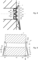
- FIG 8 is an enlargement of zone VIII of the figure 4 .
- the assembly formed by the outer wall 59 of the female polarizing stud 55, by the outer edges 61 of the female polarizing stud 55 and by the cavity 63 of the female polarizing stud 55 defines the cooperation face 51 of the polarizing tip 49.
- the cooperation face 51 has a geometry complementary to that of the cooperation face 47 of the corrector 29 of the reel 1.
- the male keyed stud 53 of the keyed 29 has a tapered outer wall 73 extended at its first end by an outer edge 75 cooperating with the cavity 63 of the female keyed stud 55 of the keyed tip 49 and at the level of its second end by two cavities 77, 79 whose inner edges define two abutments 81, 83 inside which are received the outer edges 61 of the female polarizing stud 55 of the polarizing end piece 49.
- the cavities 77, 79 are themselves same extended by a connecting edge 85 providing the connection with a cup 87 arranged on the periphery of the cooperation face 47.
- the outer wall 73 of the male foolproof stud 53 adopts a cylindrical rather than a frustoconical shape.
- the assembly formed by the connecting edge 85, by the cavities 77, 79, by the outer wall 73 of the male keyed stud 53 and by the outer edge 75 of the male keyed stud 53 defines the cooperation face 47 of the keyed 29 of the reel 1 whose geometry is complementary to that of the cooperation face 51 of the polarizing tip 49 of the roll 3 of paper.
- non-compliant is understood to mean a roll of paper which does not include a foolproof tip or a roll of paper whose face for cooperating with the foolproof tip of the roll is not shaped to cooperate with the face of cooperation of the reel locating device.
- the cup 87 arranged on the periphery of the cooperation face 47 of the corrector 29.
- the cup 87 comprises a frustoconical outer wall 89 defining a slope oriented towards the bottom edge of the reel.
- the frustoconical outer wall 89 is made of a slippery material chosen so that if a non-compliant roller is mounted on the corrector, the frictional force resulting from the contact between the recess 37 of the tube 35 of the roller 3 and the frustoconical outer wall 89 keyed 29 is such that a movement of the roller 3 to the lower edge of the reel is allowed.
- the anti-fraud device 27 may comprise one or more blocking notches 91, mounted on the lower edge of the reel, which may be formed by the support base 15 of the reel.
- the blocking ridges 91 extend from the lower edge of the reel towards the corrector 29 and are arranged so as to exert a frictional force against a lower wall 93 of the roll 3 of paper, at the level of the zone 95 shown in figure 9 , after a non-compliant roll has been driven in the direction of the lower edge 13 of the reel by the cup 87.
- the anti-fraud device 27 comprises one or more locking studs 97 which are arranged in the reel so as to exert a frictional force against the side wall 71 of the roll 3 of paper, at the level of the zone 99 shown in figure 9 , after a non-compliant roll has been driven in the direction of the lower edge of the reel by the cup 87.
- the locking pins 97 are mounted on the support arms 19, 21. When the reel does not have a support arm, the locking studs 97 are mounted directly on the inside face of the casing 5.
Landscapes
- Health & Medical Sciences (AREA)
- Public Health (AREA)
- Unwinding Webs (AREA)
Claims (9)
- Kombination aus einem manipulationssicheren Endstück (49) und einer Papierrolle (3), die dazu bestimmt ist, abgewickelt zu werden, wobei die Rolle (3) in der Art ein Rohr (35) beinhaltend ist, das eine axiale Aussparung (37) beinhaltet, um die eine Vielzahl von Papierblättern (39) gewickelt ist, wobei das manipulationssicheren Endstück (49) angepasst ist, um mit einer Manipulationssicherung (29) einer Abrollvorrichtung (1) zusammenzuwirken, und eine Zusammenwirkungsfläche (51) beinhaltet, die dazu bestimmt ist, um mit einer Zusammenwirkungsfläche (47) der Manipulationssicherung (29) der Abrollvorrichtung (1) zusammenzuwirken, wobei die Zusammenwirkungsfläche (51) des manipulationssicheren Endstücks (49) vorgesehen ist, um ins Innere der axialen Aussparung (37) des Rohres (35) der Rolle (3) einzudringen, wenn das manipulationssichere Endstück (49) an der Rolle (3) befestigt ist, dadurch gekennzeichnet, dass die manipulationssichere Endstück (49) aus biologisch abbaubarem Material, wie Cellulose gefertigt ist.
- Kombination nach Anspruch 1, dadurch gekennzeichnet, dass das manipulationssichere Endstück (49) eine Kappe (57) beinhaltet, die konzentrisch eine Manipulationssicherungs-Kuppelbuchse (55) aufnimmt, die angepasst ist, um einen Manipulationssicherungs-Kuppelstecker (53) aufzunehmen, der auf der Manipulationssicherung (29) der Abrollvorrichtung (1) angeordnet ist, wenn das manipulationssichere Endstück (49) auf der Papierrolle (3) befestigt ist, die dazu bestimmt ist, abgewickelt zu werden, und wenn die Rolle (3) auf der Abrollvorrichtung (1) montiert ist.
- Kombination nach Anspruch 2, dadurch gekennzeichnet, dass das manipulationssichere Endstück (49) einen Ansatz (67) beinhaltet, der sich radial nach außerhalb der Kappe (57) erstreckt, und eine Anlegeoberfläche an eine Seitenwand (71) der Papierrolle (3) definiert, wenn das manipulationssichere Endstück (49) in der axialen Aussparung (37) des Rohres (35) der Rolle (3) montiert ist.
- Baugruppe, Folgendes beinhaltend:- eine Kombination nach einem der vorstehenden Ansprüche,- eine Abrollvorrichtung (1), Folgendes beinhaltend:° eine Haltekuppel (23), die konfiguriert ist, um die Papierrolle (3) zu halten,° eine Betrugsbekämpfungsvorrichtung (27), die eine Manipulationssicherung (29) beinhaltet, die gegenüber der Haltekuppel (23) montiert ist,wobei die Manipulationssicherung (29) und die Haltekuppel (23) gestaltet sind, um die Rolle (3) zu halten, und um die Drehung der Rolle (3) auf einer Drehachse (33) zu erlauben, die durch die Haltekuppel (23) und durch die Manipulationssicherung (29) verläuft, wenn die Rolle (3) auf der Abrollvorrichtung (1) montiert ist,wobei die Manipulationssicherung (29) weiter eine Zusammenwirkungsfläche (47) beinhaltet, die mit dem manipulationssicheren Endstück (49) zusammenwirkt, das auf der Rolle (3) befestigt ist, wenn die Rolle (3) auf der Abrollvorrichtung (1) montiert ist,wobei die Zusammenwirkungsfläche (47) der Manipulationssicherung (29) vorgesehen ist, um mindestens teilweise ins Innere der axialen Aussparung (37) des Rohres (35) der Rolle (3) einzudringen, und um mit der Zusammenwirkungsfläche (51) des manipulationssicheren Endstücks (49) zusammenzuwirken, wenn die Rolle (3) von der Haltekuppel (23) und von der Manipulationssicherung (29) gehalten wird.
- Baugruppe nach Anspruch 4, dadurch gekennzeichnet, dass die Abrollvorrichtung (1) einen oberen Rand (11) und einen unteren Rand (13) beinhaltet, wobei die Manipulationssicherung (29) zwischen dem oberen und unteren Rand positioniert ist, und dadurch, dass:- die Manipulationssicherung (29) eine Kappe (87) beinhaltet, die eine kegelstumpfförmige Außengleitwand (89) beinhaltet, die an der Peripherie der Zusammenwirkungsfläche (47) der Manipulationssicherung (29) angeordnet ist, die eine Neigung definiert, die zum unteren Rand (13) der Abrollvorrichtung (1) gerichtet ist, um die Rolle (3) in Richtung des unteren Randes (13) zu treiben, wenn die Rolle (3) in der Abrollvorrichtung (1) montiert ist, und wenn die Rolle (3) kein manipulationssicheres Endstück (49) beinhaltet, oder wenn das manipulationssichere Endstück (49) der Rolle (3) nicht mit der Zusammenwirkungsfläche (47) der Manipulationssicherung (29) zusammenwirkt, und- die Betrugsbekämpfungsvorrichtung (27) mindestens einen Sperrgrat (91) beinhaltet, der am unteren Rand (13) der Abrollvorrichtung (1) montiert ist, der sich in Richtung der Manipulationssicherung (29) erstreckt und derart angeordnet ist, um eine Reibungskraft auf eine untere Wand (93) der Papierrolle (3) auszuüben, nachdem die Rolle (3) durch die Kappe (87) in Richtung des unteren Randes (13) getrieben worden ist.
- Baugruppe nach Anspruch 5, dadurch gekennzeichnet, dass die Betrugsbekämpfungsvorrichtung (27) mindestens einen Sperrnippel (97) beinhaltet, der angeordnet ist, um eine Reibungskraft auf eine Seitenwand (71) der Papierrolle (3) auszuüben, nachdem die Rolle (3) durch die Kappe (87) der Manipulationssicherung (29) in Richtung des unteren Randes der Abrollvorrichtung (1) getrieben worden ist.
- Baugruppe nach Anspruch 6, dadurch gekennzeichnet, dass die Abrollvorrichtung (1) zwei Haltearme (19, 21) beinhaltet, die Haltekuppel (23) und die Manipulationssicherung (29) jeweils auf jedem der Haltearme (19, 21) montiert sind, und dadurch, dass der mindestens eine Sperrnippel (97) auf mindestens einem der Haltearme (19, 21) montiert ist.
- Baugruppe nach Anspruch 7, dadurch gekennzeichnet, dass die Abrollvorrichtung (1) beinhaltet:- ein Gehäuse (5),- einen Haltesockel (15), der im Inneren des Gehäuses (5) auf Höhe des unteren Randes (13) der Abrollvorrichtung (1) montiert ist,wobei der mindestens eine Sperrgrat (91) an einer oberen Wand (17) des Haltesockels (15) montiert ist, und dadurch, dass jeder der Haltearme (19, 21) ein erstes Ende (19a, 21a) und ein zweites Ende (19b, 21b) beinhaltet, wobei das erste Ende (19a, 21a) an der oberen Wand (17) des Haltesockels (15) montiert ist, und die Haltekuppel (23) und die Manipulationssicherung (29) jeweils auf Höhe des zweiten Endes (19b, 21b) montiert sind.
- Baugruppe nach einem der Ansprüche 4 bis 8, dadurch gekennzeichnet, dass die Zusammenwirkungsfläche (47) der Manipulationssicherung (29) einen Manipulationssicherungs-Kuppelstecker (53) beinhaltet, der vorgesehen ist, um in eine Manipulationssicherungs-Kuppelbuchse (55) einzudringen, die an dem manipulationssicheren Endstück (49) angeordnet ist, das an der Rolle (3) befestigt ist, wenn die Rolle (3) in der Abrollvorrichtung (1) montiert ist.
Applications Claiming Priority (1)
| Application Number | Priority Date | Filing Date | Title |
|---|---|---|---|
| FR1903304A FR3094194B1 (fr) | 2019-03-28 | 2019-03-28 | Dévidoir de rouleau de papier et embout détrompeur pour rouleau de papier |
Publications (4)
| Publication Number | Publication Date |
|---|---|
| EP3714751A1 EP3714751A1 (de) | 2020-09-30 |
| EP3714751C0 EP3714751C0 (de) | 2023-06-07 |
| EP3714751B1 true EP3714751B1 (de) | 2023-06-07 |
| EP3714751B2 EP3714751B2 (de) | 2025-12-03 |
Family
ID=67441408
Family Applications (1)
| Application Number | Title | Priority Date | Filing Date |
|---|---|---|---|
| EP20166879.5A Active EP3714751B2 (de) | 2019-03-28 | 2020-03-30 | Papierrollen-abwickelvorrichtung und führungshülse für papierrolle |
Country Status (2)
| Country | Link |
|---|---|
| EP (1) | EP3714751B2 (de) |
| FR (1) | FR3094194B1 (de) |
Citations (6)
| Publication number | Priority date | Publication date | Assignee | Title |
|---|---|---|---|---|
| US6092760A (en) * | 1999-04-29 | 2000-07-25 | Hedrick; Renaya Willett | Easy roll |
| EP1284231A2 (de) | 2001-08-18 | 2003-02-19 | Frank Germeroth | Stopfen |
| US20070075180A1 (en) | 2005-10-03 | 2007-04-05 | Cascades Canada Inc. | Paper roll and paper roll dispenser |
| US7568653B2 (en) * | 2005-06-01 | 2009-08-04 | Sca Hygiene Products Ab | Adapter for a solid or coreless roll of hygiene paper |
| WO2012073203A2 (en) | 2010-12-02 | 2012-06-07 | Kimberly-Clark Worldwide, Inc. | Dispenser supply roll engagement system |
| US20170209006A1 (en) | 2016-01-26 | 2017-07-27 | Georgia-Pacific Consumer Products Lp | Mechanical dispenser for perforated sheet products |
Family Cites Families (1)
| Publication number | Priority date | Publication date | Assignee | Title |
|---|---|---|---|---|
| US10172501B2 (en) * | 2015-09-10 | 2019-01-08 | Von Drehle Corporation | Paper towel dispenser with roll holder and rotating plug assembly |
-
2019
- 2019-03-28 FR FR1903304A patent/FR3094194B1/fr active Active
-
2020
- 2020-03-30 EP EP20166879.5A patent/EP3714751B2/de active Active
Patent Citations (6)
| Publication number | Priority date | Publication date | Assignee | Title |
|---|---|---|---|---|
| US6092760A (en) * | 1999-04-29 | 2000-07-25 | Hedrick; Renaya Willett | Easy roll |
| EP1284231A2 (de) | 2001-08-18 | 2003-02-19 | Frank Germeroth | Stopfen |
| US7568653B2 (en) * | 2005-06-01 | 2009-08-04 | Sca Hygiene Products Ab | Adapter for a solid or coreless roll of hygiene paper |
| US20070075180A1 (en) | 2005-10-03 | 2007-04-05 | Cascades Canada Inc. | Paper roll and paper roll dispenser |
| WO2012073203A2 (en) | 2010-12-02 | 2012-06-07 | Kimberly-Clark Worldwide, Inc. | Dispenser supply roll engagement system |
| US20170209006A1 (en) | 2016-01-26 | 2017-07-27 | Georgia-Pacific Consumer Products Lp | Mechanical dispenser for perforated sheet products |
Non-Patent Citations (2)
| Title |
|---|
| ANONYMOUS: "Pappe", WIKIPEDIA, 31 January 2024 (2024-01-31), pages 1 - 5, XP093248288, Retrieved from the Internet <URL:https://de.wikipedia.org/w/index.php?title=Pappe&oldid=241719257> [retrieved on 20250210] |
| ANONYMOUS: "Zellstoff ", WIKIPEDIA, 31 January 2024 (2024-01-31), pages 1 - 6, XP093248289, Retrieved from the Internet <URL:https://de.wikipedia.org/w/index.php?title=Zellstoff&oldid=241727395> [retrieved on 20250210] |
Also Published As
| Publication number | Publication date |
|---|---|
| EP3714751C0 (de) | 2023-06-07 |
| FR3094194B1 (fr) | 2022-10-21 |
| EP3714751B2 (de) | 2025-12-03 |
| EP3714751A1 (de) | 2020-09-30 |
| FR3094194A1 (fr) | 2020-10-02 |
Similar Documents
| Publication | Publication Date | Title |
|---|---|---|
| WO2008047035A2 (fr) | Dispositif de distribution de produit fluide | |
| CA3072412A1 (fr) | Dispositif de conditionnement d'objet, ensemble et procede d'extraction correspondant | |
| EP2088909B1 (de) | Einwegendstück für eine wischmaterialrolle und spendervorrichtung für wischmaterial mit derartigem endstück | |
| EP0425334A2 (de) | Einbruchsicherer Papierrollenspender und Anpassungsvorrichtung dafür | |
| EP3253269A1 (de) | Vorrichtung zur ausgabe von streifen eines flexiblen materials auf einer spule in horizontaler oder vertikaler positionierung | |
| FR2997971A1 (fr) | Embout pour sommet de cone ou poteau de signalisation comprenant une ouverture | |
| EP3714751B1 (de) | Papierrollen-abwickelvorrichtung und führungshülse für papierrolle | |
| EP2366275B1 (de) | Vorrichtung zur Messerbefestigung auf den Rotor eines Böschungsmähers | |
| EP2056703A2 (de) | Blockierschutzvorrichtung und dynamische bremsensteuerung in einer maschine zur automatischen verteilung geschnittener wischtücher | |
| EP1870541B1 (de) | Vorrichtung zum Befestigen eines Schließstators | |
| EP2966741A1 (de) | Installationshalterung für einbaudose und elektrische geräte mit einer solchen halterung | |
| CA2452659C (fr) | Dispositif d'alimentation en papier en rouleau pour machine imprimante | |
| FR2879091A1 (fr) | Dispositif de liaison entre un rouleau sans mandrin et un distributeur, rouleau et distributeur associes | |
| WO2022101186A1 (fr) | Diffuseur pour générateur d'aérosol | |
| EP3724000B1 (de) | Rolle für möbelstück | |
| FR3062702A1 (fr) | Dispositif pour l'accouplement de deux tubes avec pre-montage | |
| FR2695114A1 (fr) | Distributeur de papier en rouleau. | |
| WO2002016217A1 (fr) | Bouchon comportant des moyens de blocage de la deformation radiale de la bague d'inviolabilite | |
| FR3167415A1 (fr) | Clip de maintien multifonction et support associé | |
| FR3066094A1 (fr) | Dispositif de fixation d’accessoires a radiateur | |
| WO2013004975A2 (fr) | Kit de reserve de papier toilette, gaine et etui d'un tel kit, procede de fabrication afferent | |
| EP3343714A1 (de) | System zum anbringen einer fassade an einer einbaudose | |
| FR3101618A1 (fr) | Gobelet à usage unique | |
| FR2660958A1 (fr) | Dispositif de protection, notamment contre la poussiere, d'un cylindre de surete, et cylindre de surete equipe d'un tel dispositif. | |
| WO2003021062A1 (fr) | Poignee de porte |
Legal Events
| Date | Code | Title | Description |
|---|---|---|---|
| PUAI | Public reference made under article 153(3) epc to a published international application that has entered the european phase |
Free format text: ORIGINAL CODE: 0009012 |
|
| STAA | Information on the status of an ep patent application or granted ep patent |
Free format text: STATUS: THE APPLICATION HAS BEEN PUBLISHED |
|
| AK | Designated contracting states |
Kind code of ref document: A1 Designated state(s): AL AT BE BG CH CY CZ DE DK EE ES FI FR GB GR HR HU IE IS IT LI LT LU LV MC MK MT NL NO PL PT RO RS SE SI SK SM TR |
|
| AX | Request for extension of the european patent |
Extension state: BA ME |
|
| RAP1 | Party data changed (applicant data changed or rights of an application transferred) |
Owner name: PAREDES FAB |
|
| STAA | Information on the status of an ep patent application or granted ep patent |
Free format text: STATUS: REQUEST FOR EXAMINATION WAS MADE |
|
| 17P | Request for examination filed |
Effective date: 20210330 |
|
| RAX | Requested extension states of the european patent have changed |
Extension state: BA Payment date: 20210330 Extension state: ME Payment date: 20210330 |
|
| RBV | Designated contracting states (corrected) |
Designated state(s): AL AT BE BG CH CY CZ DE DK EE ES FI FR GB GR HR HU IE IS IT LI LT LU LV MC MK MT NL NO PL PT RO RS SE SI SK SM TR |
|
| GRAP | Despatch of communication of intention to grant a patent |
Free format text: ORIGINAL CODE: EPIDOSNIGR1 |
|
| STAA | Information on the status of an ep patent application or granted ep patent |
Free format text: STATUS: GRANT OF PATENT IS INTENDED |
|
| RIN1 | Information on inventor provided before grant (corrected) |
Inventor name: AUROUX, MICHEL Inventor name: PONCELET, GILLES |
|
| INTG | Intention to grant announced |
Effective date: 20230104 |
|
| GRAS | Grant fee paid |
Free format text: ORIGINAL CODE: EPIDOSNIGR3 |
|
| GRAA | (expected) grant |
Free format text: ORIGINAL CODE: 0009210 |
|
| STAA | Information on the status of an ep patent application or granted ep patent |
Free format text: STATUS: THE PATENT HAS BEEN GRANTED |
|
| AK | Designated contracting states |
Kind code of ref document: B1 Designated state(s): AL AT BE BG CH CY CZ DE DK EE ES FI FR GB GR HR HU IE IS IT LI LT LU LV MC MK MT NL NO PL PT RO RS SE SI SK SM TR |
|
| REG | Reference to a national code |
Ref country code: GB Ref legal event code: FG4D Free format text: NOT ENGLISH |
|
| REG | Reference to a national code |
Ref country code: CH Ref legal event code: EP Ref country code: AT Ref legal event code: REF Ref document number: 1572234 Country of ref document: AT Kind code of ref document: T Effective date: 20230615 |
|
| REG | Reference to a national code |
Ref country code: DE Ref legal event code: R096 Ref document number: 602020011507 Country of ref document: DE |
|
| U01 | Request for unitary effect filed |
Effective date: 20230706 |
|
| U07 | Unitary effect registered |
Designated state(s): AT BE BG DE DK EE FI FR IT LT LU LV MT NL PT SE SI Effective date: 20230717 |
|
| REG | Reference to a national code |
Ref country code: LT Ref legal event code: MG9D |
|
| PG25 | Lapsed in a contracting state [announced via postgrant information from national office to epo] |
Ref country code: NO Free format text: LAPSE BECAUSE OF FAILURE TO SUBMIT A TRANSLATION OF THE DESCRIPTION OR TO PAY THE FEE WITHIN THE PRESCRIBED TIME-LIMIT Effective date: 20230907 Ref country code: ES Free format text: LAPSE BECAUSE OF FAILURE TO SUBMIT A TRANSLATION OF THE DESCRIPTION OR TO PAY THE FEE WITHIN THE PRESCRIBED TIME-LIMIT Effective date: 20230607 |
|
| PG25 | Lapsed in a contracting state [announced via postgrant information from national office to epo] |
Ref country code: RS Free format text: LAPSE BECAUSE OF FAILURE TO SUBMIT A TRANSLATION OF THE DESCRIPTION OR TO PAY THE FEE WITHIN THE PRESCRIBED TIME-LIMIT Effective date: 20230607 Ref country code: HR Free format text: LAPSE BECAUSE OF FAILURE TO SUBMIT A TRANSLATION OF THE DESCRIPTION OR TO PAY THE FEE WITHIN THE PRESCRIBED TIME-LIMIT Effective date: 20230607 Ref country code: GR Free format text: LAPSE BECAUSE OF FAILURE TO SUBMIT A TRANSLATION OF THE DESCRIPTION OR TO PAY THE FEE WITHIN THE PRESCRIBED TIME-LIMIT Effective date: 20230908 |
|
| PG25 | Lapsed in a contracting state [announced via postgrant information from national office to epo] |
Ref country code: SK Free format text: LAPSE BECAUSE OF FAILURE TO SUBMIT A TRANSLATION OF THE DESCRIPTION OR TO PAY THE FEE WITHIN THE PRESCRIBED TIME-LIMIT Effective date: 20230607 |
|
| PG25 | Lapsed in a contracting state [announced via postgrant information from national office to epo] |
Ref country code: IS Free format text: LAPSE BECAUSE OF FAILURE TO SUBMIT A TRANSLATION OF THE DESCRIPTION OR TO PAY THE FEE WITHIN THE PRESCRIBED TIME-LIMIT Effective date: 20231007 |
|
| PG25 | Lapsed in a contracting state [announced via postgrant information from national office to epo] |
Ref country code: SM Free format text: LAPSE BECAUSE OF FAILURE TO SUBMIT A TRANSLATION OF THE DESCRIPTION OR TO PAY THE FEE WITHIN THE PRESCRIBED TIME-LIMIT Effective date: 20230607 Ref country code: SK Free format text: LAPSE BECAUSE OF FAILURE TO SUBMIT A TRANSLATION OF THE DESCRIPTION OR TO PAY THE FEE WITHIN THE PRESCRIBED TIME-LIMIT Effective date: 20230607 Ref country code: RO Free format text: LAPSE BECAUSE OF FAILURE TO SUBMIT A TRANSLATION OF THE DESCRIPTION OR TO PAY THE FEE WITHIN THE PRESCRIBED TIME-LIMIT Effective date: 20230607 Ref country code: IS Free format text: LAPSE BECAUSE OF FAILURE TO SUBMIT A TRANSLATION OF THE DESCRIPTION OR TO PAY THE FEE WITHIN THE PRESCRIBED TIME-LIMIT Effective date: 20231007 Ref country code: CZ Free format text: LAPSE BECAUSE OF FAILURE TO SUBMIT A TRANSLATION OF THE DESCRIPTION OR TO PAY THE FEE WITHIN THE PRESCRIBED TIME-LIMIT Effective date: 20230607 |
|
| PG25 | Lapsed in a contracting state [announced via postgrant information from national office to epo] |
Ref country code: PL Free format text: LAPSE BECAUSE OF FAILURE TO SUBMIT A TRANSLATION OF THE DESCRIPTION OR TO PAY THE FEE WITHIN THE PRESCRIBED TIME-LIMIT Effective date: 20230607 |
|
| REG | Reference to a national code |
Ref country code: DE Ref legal event code: R026 Ref document number: 602020011507 Country of ref document: DE |
|
| PLBI | Opposition filed |
Free format text: ORIGINAL CODE: 0009260 |
|
| PLAX | Notice of opposition and request to file observation + time limit sent |
Free format text: ORIGINAL CODE: EPIDOSNOBS2 |
|
| U20 | Renewal fee for the european patent with unitary effect paid |
Year of fee payment: 5 Effective date: 20240216 |
|
| 26 | Opposition filed |
Opponent name: KRAUS & LEDERER PARTGMBB Effective date: 20240306 |
|
| PLBB | Reply of patent proprietor to notice(s) of opposition received |
Free format text: ORIGINAL CODE: EPIDOSNOBS3 |
|
| PG25 | Lapsed in a contracting state [announced via postgrant information from national office to epo] |
Ref country code: MC Free format text: LAPSE BECAUSE OF FAILURE TO SUBMIT A TRANSLATION OF THE DESCRIPTION OR TO PAY THE FEE WITHIN THE PRESCRIBED TIME-LIMIT Effective date: 20230607 |
|
| PG25 | Lapsed in a contracting state [announced via postgrant information from national office to epo] |
Ref country code: MC Free format text: LAPSE BECAUSE OF FAILURE TO SUBMIT A TRANSLATION OF THE DESCRIPTION OR TO PAY THE FEE WITHIN THE PRESCRIBED TIME-LIMIT Effective date: 20230607 |
|
| PG25 | Lapsed in a contracting state [announced via postgrant information from national office to epo] |
Ref country code: IE Free format text: LAPSE BECAUSE OF NON-PAYMENT OF DUE FEES Effective date: 20240330 |
|
| PG25 | Lapsed in a contracting state [announced via postgrant information from national office to epo] |
Ref country code: IE Free format text: LAPSE BECAUSE OF NON-PAYMENT OF DUE FEES Effective date: 20240330 |
|
| U20 | Renewal fee for the european patent with unitary effect paid |
Year of fee payment: 6 Effective date: 20250331 |
|
| PGFP | Annual fee paid to national office [announced via postgrant information from national office to epo] |
Ref country code: CH Payment date: 20250401 Year of fee payment: 6 |
|
| PG25 | Lapsed in a contracting state [announced via postgrant information from national office to epo] |
Ref country code: CY Free format text: LAPSE BECAUSE OF FAILURE TO SUBMIT A TRANSLATION OF THE DESCRIPTION OR TO PAY THE FEE WITHIN THE PRESCRIBED TIME-LIMIT; INVALID AB INITIO Effective date: 20200330 |
|
| PG25 | Lapsed in a contracting state [announced via postgrant information from national office to epo] |
Ref country code: HU Free format text: LAPSE BECAUSE OF FAILURE TO SUBMIT A TRANSLATION OF THE DESCRIPTION OR TO PAY THE FEE WITHIN THE PRESCRIBED TIME-LIMIT; INVALID AB INITIO Effective date: 20200330 |
|
| PUAH | Patent maintained in amended form |
Free format text: ORIGINAL CODE: 0009272 |
|
| STAA | Information on the status of an ep patent application or granted ep patent |
Free format text: STATUS: PATENT MAINTAINED AS AMENDED |
|
| REG | Reference to a national code |
Ref country code: CH Ref legal event code: M12 Free format text: ST27 STATUS EVENT CODE: U-0-0-M10-M12 (AS PROVIDED BY THE NATIONAL OFFICE) Effective date: 20251105 |
|
| 27A | Patent maintained in amended form |
Effective date: 20251203 |
|
| AK | Designated contracting states |
Kind code of ref document: B2 Designated state(s): AL AT BE BG CH CY CZ DE DK EE ES FI FR GB GR HR HU IE IS IT LI LT LU LV MC MK MT NL NO PL PT RO RS SE SI SK SM TR |
|
| PG25 | Lapsed in a contracting state [announced via postgrant information from national office to epo] |
Ref country code: TR Free format text: LAPSE BECAUSE OF FAILURE TO SUBMIT A TRANSLATION OF THE DESCRIPTION OR TO PAY THE FEE WITHIN THE PRESCRIBED TIME-LIMIT Effective date: 20230607 |
|
| REG | Reference to a national code |
Ref country code: CH Ref legal event code: U11 Free format text: ST27 STATUS EVENT CODE: U-0-0-U10-U11 (AS PROVIDED BY THE NATIONAL OFFICE) Effective date: 20260401 |
|
| PGFP | Annual fee paid to national office [announced via postgrant information from national office to epo] |
Ref country code: GB Payment date: 20260330 Year of fee payment: 7 |