EP3714801A1 - Minimal-invasives nahtplatzierungssystem - Google Patents
Minimal-invasives nahtplatzierungssystem Download PDFInfo
- Publication number
- EP3714801A1 EP3714801A1 EP20166182.4A EP20166182A EP3714801A1 EP 3714801 A1 EP3714801 A1 EP 3714801A1 EP 20166182 A EP20166182 A EP 20166182A EP 3714801 A1 EP3714801 A1 EP 3714801A1
- Authority
- EP
- European Patent Office
- Prior art keywords
- suture
- lumen
- placement system
- guide
- implant
- Prior art date
- Legal status (The legal status is an assumption and is not a legal conclusion. Google has not performed a legal analysis and makes no representation as to the accuracy of the status listed.)
- Granted
Links
Images


Classifications
-
- A—HUMAN NECESSITIES
- A61—MEDICAL OR VETERINARY SCIENCE; HYGIENE
- A61B—DIAGNOSIS; SURGERY; IDENTIFICATION
- A61B17/00—Surgical instruments, devices or methods
- A61B17/04—Surgical instruments, devices or methods for suturing wounds; Holders or packages for needles or suture materials
- A61B17/0469—Suturing instruments for use in minimally invasive surgery, e.g. endoscopic surgery
-
- A—HUMAN NECESSITIES
- A61—MEDICAL OR VETERINARY SCIENCE; HYGIENE
- A61B—DIAGNOSIS; SURGERY; IDENTIFICATION
- A61B17/00—Surgical instruments, devices or methods
- A61B17/04—Surgical instruments, devices or methods for suturing wounds; Holders or packages for needles or suture materials
- A61B17/0482—Needle or suture guides
-
- A—HUMAN NECESSITIES
- A61—MEDICAL OR VETERINARY SCIENCE; HYGIENE
- A61B—DIAGNOSIS; SURGERY; IDENTIFICATION
- A61B17/00—Surgical instruments, devices or methods
- A61B17/04—Surgical instruments, devices or methods for suturing wounds; Holders or packages for needles or suture materials
- A61B17/0487—Suture clamps, clips or locks, e.g. for replacing suture knots; Instruments for applying or removing suture clamps, clips or locks
-
- A—HUMAN NECESSITIES
- A61—MEDICAL OR VETERINARY SCIENCE; HYGIENE
- A61B—DIAGNOSIS; SURGERY; IDENTIFICATION
- A61B17/00—Surgical instruments, devices or methods
- A61B17/04—Surgical instruments, devices or methods for suturing wounds; Holders or packages for needles or suture materials
- A61B17/0491—Sewing machines for surgery
-
- A—HUMAN NECESSITIES
- A61—MEDICAL OR VETERINARY SCIENCE; HYGIENE
- A61B—DIAGNOSIS; SURGERY; IDENTIFICATION
- A61B17/00—Surgical instruments, devices or methods
- A61B17/0057—Implements for plugging an opening in the wall of a hollow or tubular organ, e.g. for sealing a vessel puncture or closing a cardiac septal defect
-
- A—HUMAN NECESSITIES
- A61—MEDICAL OR VETERINARY SCIENCE; HYGIENE
- A61B—DIAGNOSIS; SURGERY; IDENTIFICATION
- A61B17/00—Surgical instruments, devices or methods
- A61B17/04—Surgical instruments, devices or methods for suturing wounds; Holders or packages for needles or suture materials
- A61B17/0485—Devices or means, e.g. loops, for capturing the suture thread and threading it through an opening of a suturing instrument or needle eyelet
-
- A—HUMAN NECESSITIES
- A61—MEDICAL OR VETERINARY SCIENCE; HYGIENE
- A61B—DIAGNOSIS; SURGERY; IDENTIFICATION
- A61B17/00—Surgical instruments, devices or methods
- A61B17/04—Surgical instruments, devices or methods for suturing wounds; Holders or packages for needles or suture materials
- A61B17/06—Needles ; Sutures; Needle-suture combinations; Holders or packages for needles or suture materials
- A61B17/06066—Needles, e.g. needle tip configurations
-
- A—HUMAN NECESSITIES
- A61—MEDICAL OR VETERINARY SCIENCE; HYGIENE
- A61B—DIAGNOSIS; SURGERY; IDENTIFICATION
- A61B17/00—Surgical instruments, devices or methods
- A61B17/00234—Surgical instruments, devices or methods for minimally invasive surgery
- A61B2017/00238—Type of minimally invasive operation
- A61B2017/00243—Type of minimally invasive operation cardiac
-
- A—HUMAN NECESSITIES
- A61—MEDICAL OR VETERINARY SCIENCE; HYGIENE
- A61B—DIAGNOSIS; SURGERY; IDENTIFICATION
- A61B17/00—Surgical instruments, devices or methods
- A61B17/00234—Surgical instruments, devices or methods for minimally invasive surgery
- A61B2017/00358—Snares for grasping
-
- A—HUMAN NECESSITIES
- A61—MEDICAL OR VETERINARY SCIENCE; HYGIENE
- A61B—DIAGNOSIS; SURGERY; IDENTIFICATION
- A61B17/00—Surgical instruments, devices or methods
- A61B2017/00477—Coupling
-
- A—HUMAN NECESSITIES
- A61—MEDICAL OR VETERINARY SCIENCE; HYGIENE
- A61B—DIAGNOSIS; SURGERY; IDENTIFICATION
- A61B17/00—Surgical instruments, devices or methods
- A61B17/04—Surgical instruments, devices or methods for suturing wounds; Holders or packages for needles or suture materials
- A61B17/0401—Suture anchors, buttons or pledgets, i.e. means for attaching sutures to bone, cartilage or soft tissue; Instruments for applying or removing suture anchors
- A61B2017/0446—Means for attaching and blocking the suture in the suture anchor
- A61B2017/0454—Means for attaching and blocking the suture in the suture anchor the anchor being crimped or clamped on the suture
-
- A—HUMAN NECESSITIES
- A61—MEDICAL OR VETERINARY SCIENCE; HYGIENE
- A61B—DIAGNOSIS; SURGERY; IDENTIFICATION
- A61B90/00—Instruments, implements or accessories specially adapted for surgery or diagnosis and not covered by any of the groups A61B1/00 - A61B50/00, e.g. for luxation treatment or for protecting wound edges
- A61B90/08—Accessories or related features not otherwise provided for
- A61B2090/0807—Indication means
- A61B2090/0811—Indication means for the position of a particular part of an instrument with respect to the rest of the instrument, e.g. position of the anvil of a stapling instrument
Definitions
- the claimed invention relates to surgical devices, and more specifically to suture placement systems for use in minimally invasive surgeries.
- the RAM® Device may be used in conjunction with a SEW-EASY® Device, also sold by LSI Solutions, Inc., for the automated placement of those same sutures through a sewing cuff of a prosthetic heart valve or an annuloplasty ring.
- a SEW-EASY® Device also sold by LSI Solutions, Inc.
- surgeons are able to accomplish most of their surgical actions through very small incisions (on the order of 5cm) made in one of the intercostal spaces between a patient's ribs. This is particularly beneficial to the patient, as the previous alternatives were much larger openings, including the use of a full sternotomy.
- Minimally invasive surgery is less traumatic to patients and often enables them to be on cardio-pulmonary bypass (CPB) machines for shorter times, thereby improving patient outcomes and reducing recovery times.
- CPB cardio-pulmonary bypass
- the pressure in the right atrium is such that the blood would tend to fill partially into such a cannula, and of course, there would be blood within the right atrium which would also, unfortunately, completely obscure a surgeon's view of the right atrium and the tissues of the tricuspid valve if such an approach were to be taken. Even echocardiography, on its own, would have a difficult time allowing the surgeon to orient a suturing device through the blood field for a series of related stitches. Therefore, it would be desirable to have a minimally invasive suture placement system and method which would enable reliable suture placement around a cardiac valve, such as a tricuspid valve, even under conditions of zero direct and zero endoscopic visibility to enable minimally invasive beating heart surgery for better patient outcomes.
- a suture placement system has a plate defining a first opening spaced from a second opening.
- the suture placement system also has a first lumen having proximal and distal ends, wherein the distal end of the first lumen is coupled to the first opening.
- the suture placement system further has a second lumen having proximal and distal ends, wherein the distal end of the second lumen is coupled to the second opening.
- the suture placement system also has a guide coupled to the plate.
- a method of minimally invasive suture placement is also disclosed.
- a minimally invasive suturing device is used to place a stitch of a first implant suture in tissue.
- a first end of the implant suture is pulled through a second lumen coupled to a plate.
- the first end of the implant suture is secured relative to the second lumen such that a distal end of the second lumen is held against the tissue.
- a second end of the implant suture is secured relative to a first lumen such that a distal end of the first lumen is held against the tissue.
- a follower on the minimally invasive suturing device is slid down a guide coupled to the plate at a fixed spacing from at least one of the first and second lumens until a tissue bite area of the suturing device coupled to the follower contacts the tissue.
- a stitch of a second implant suture is placed into the tissue at a position determined at least in part by an arc which the minimally invasive suturing device is able to follow by having the follower pivot on the guide.
- the claimed invention relates to surgical devices, and more specifically to suture placement systems for use in minimally invasive surgeries.
- FIG. 1 illustrates one embodiment of a minimally invasive suturing device 30.
- the suturing device 30 has a handle 32 from which a shaft 34 extends.
- a distal sewing tip 36 resides at the end of the shaft 34.
- This particular suturing device 30 has an arcuate tissue bite area 38 facing distally along the longitudinal axis 40 of the suturing device 30.
- an implant suture for tissue implantation
- a ferrule on at least a first end of the implant suture may be loaded into the device 30 such that the ferrule on the end of the suture (not shown in this view) is held by a ferrule holder 42 in the device tip 36.
- a surgeon uses the handle 32 to manipulate the tissue bite area 38 against tissue where a suture stitch is desired.
- a lever 44 is then squeezed to actuate a needle (not visible in this view) to exit an opening 46 in the device tip 36, traverse through the tissue in the tissue bite area 38, and move into contact with the ferrule stored in the ferrule holder 42.
- the contact of the needle with the ferrule causes the ferrule to become attached to the needle, and when the surgeon releases the handle 44, the needle (with its attached ferrule) retracts back through the tissue in the tissue bite area 38 while also pulling the attached implant suture through the tissue.
- a suture stitch is formed in the tissue.
- a novel feature on the device tip 36 of this embodiment is a follower 48 coupled to the minimally invasive suturing device 30.
- the follower 48 defines an opening 50 which is configured for slideable engagement with a guide (not visible in this view, but the guide is discussed in more detail with regard to FIG. 2 ).
- FIG. 2 illustrates one embodiment of a suture placement system 52.
- the suture placement system 52 has a plate 54 defining a first opening 56 which is spaced from a second opening 58.
- the suture placement system 52 has a first lumen 60 having a proximal end 60P and a distal end 60D.
- the distal end 60D of the first lumen 60 is coupled to the first opening 56 in the plate 54.
- the suture placement system 52 also has a second lumen 62 having a proximal end 62P and a distal end 62D.
- the distal end 62D of the second lumen 62 is coupled to the second opening 58 in the plate 54.
- a guide 64 is also coupled to the plate 54.
- the second opening 58 is located between the first opening 56 and the point where the guide 64 is coupled to the plate 54.
- the guide 64 is a tube which is removably coupled to the plate 54 by an attachment suture 66 that engages the plate 54, passes through the distal end 64D of the guide tube 64, and is secured near a proximal end 64P of the guide tube 64 by a fastener 68 to keep the guide tube 64 coupled to the plate 54.
- a suitable fastener 68 is a crimpable titanium knot, such as the Ti-KNOT® fastener from LSI Solutions, Inc of Victor, NY. (www.lsisolutions.com ).
- the guide 64 could be coupled to the plate 54 using other techniques, including, but not limited to gluing, ultrasonic welding, or simply fabricating both parts from a single continuous piece of material.
- the guide 64 may have a variety of cross-sectional shapes, including, but not limited to circular, oval, square, rectangular, triangular, notched, and keyed.
- the follower 48 described in FIG. 1 is configured for slideable engagement with the guide 64 of FIG. 2 .
- the opening 50 defined by the follower 48 should have a shape which is compatible for slideable engagement with the guide 64.
- the opening 50 of the follower 48 should be sized to fit over the fastener 68 before going onto the guide 64.
- the opening 50 may comprise a partially closed opening which can be set against the guide 64 without needing to pass over the fastener 68.
- first and second lumens 60, 62 are bonded together.
- respective ends of an implantation suture will be exiting the proximal ends 60P, 62P of the lumens 60, 62.
- a single clamp may be used to grip the lumens 60, 62 to hold the suture ends in place.
- the first and second lumens 60, 62 may not be bonded together at all, but could be separate.
- at least a portion of the first and second lumens may be housed within the same suture tube.
- the suture placement system 52 also has an implant suture 70 having a first ferrule 72 on a first end 70A of the implant suture 70.
- the implant suture 70 also has a second ferrule 74 on a second end 70B of the implant suture 70.
- the implant suture 70 is partially located within the first lumen 60 such that the first end 70A of the implant suture 70 with the first ferrule 72 extends from the distal end 60D of the first lumen 60.
- the second end 70B of the implant suture 70 with the second ferrule 74 extends from the proximal end 60P of the first lumen 60.
- the implant suture 70 has one or more markings 76 to differentiate the second end 70B from the first end 70A of the implant suture 70.
- the suture placement system 52 also has a snare 78 having a snare loop 80 and a snare handle 82.
- the snare 78 is at least partially located within the second lumen 62 such that at least a portion of the snare loop 80 extends from the distal end 62D of the second lumen 62, while at least a portion of the snare handle 82 extends from the proximal end 62P of the second lumen 62.
- the snare handle 82 does not have to be a separate piece from the wire, suture, or other material which forms the snare loop 80.
- the snare handle 82 could simply be the ends of the material which forms the snare loop 80.
- FIG. 3 is a proximal-top-right perspective view of one embodiment of the plate 54 discussed above as part of the suture placement system.
- An attachment feature 84 for the guide 64 (not shown in this view) is also defined by the plate 54.
- the attachment suture 66 may be threaded around this attachment feature 84 and held in place as described above.
- the plate 54 has surface variations 86 which are configured to make the plate visible on an echocardiogram.
- the surface variations 86 take the form of notches, but other embodiments could have other shapes for surface variations, including no surface variations at all.
- the suture placement system is intended to be used in a beating heart where blood will likely obscure the distal portions of the system (including the plate) from being seen with the naked eye, loops, or an endoscope. It will be advantageous to be able to see the system on an echocardiogram, so if surface variations are not used, it may be desirable in some embodiments to coat at least a portion of the plate with a coating configured to make the plate visible on an echocardiogram. Such coatings are known to those skilled in the art. Such coatings could also be used in combination with surface variations 86. Furthermore, one or more of the plate 54, the first lumen 60, the second lumen 62, and the guide 64 may have a coating configured to make these parts visible on an echocardiogram. Additionally, it may be desirable to add such coatings to the follower 48 on the suturing device 30 and/or the distal tip 36 of the suturing device 30.
- FIGS. 4A, 4B, 4C, 4D, 4E, and 4F are proximal, left, right, distal, top, and bottom elevational views, respectively, of the plate 54 from FIG. 3 .
- the first ferrule 72 on the first end 70A of the implant suture 70 is loaded into the ferrule holder 42 of the minimally invasive suturing device 30.
- the remainder of the suture placement system 52 may be held nearby the suturing device 30 while the tissue bite area 38 is positioned against a desired tissue.
- the tissue bite area 38 is positioned against a portion of the annulus of a tricuspid valve during a minimally invasive beating heart surgery.
- echocardiography a surgeon should be able to position the tissue bite area 38 appropriately on the annulus, especially if some feature on the distal tip 36 is configured to make it echo-visible.
- the difficulty comes in trying to place subsequent stitches in appropriate relation to the first stitch of the implant suture.
- the claimed invention, and its equivalents, provide a novel solution for this difficulty.
- the suturing device 30 is removed from the blood field and the first ferrule 72 is released from the suturing device.
- the first end 70A of the implant suture 70 is pulled through the second lumen 62 by placing the first end 70A in the snare loop 80 and pulling it proximally through the second lumen 62 with the handle 82.
- the distal end 62D of the second lumen 62 and/or the second opening 58 in the plate 54 can be positioned against the tissue and the first end 70A of the implant suture 70 may be secured relative to the second lumen 62, for example, by placing a mosquito or other suitable clamp on the proximal end 62P of the second lumen 62.
- the second end 70B of the implant suture 70 is already passed through the first lumen 60. If this was not the case, an embodiment could be provided with a separate snare for pulling the second end 70B of the implant suture 70 through the first lumen 60. In our example, however, the second end 70B is already through the first lumen 60.
- the second end 70B of the implant suture 70 may then be secured relative to the first lumen 60 such that the distal end 60D of the first lumen 60 and/or the first opening 56 in the plate 54 can be positioned against the tissue and the second end 70B of the implant suture 70 may be secured relative to the first lumen 60, for example, by placing a mosquito or other suitable clamp on the proximal end 60P of the first lumen 60.
- a single clamp may be used on the proximal ends 60P, 62P of the first and second lumens 60, 62 after the suture placement system is positioned against the tissue.
- one or more integrated suture locks may come coupled to the proximal ends 60P, 62P of the first and/or second lumens 60, 62.
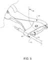
- a second implant suture 88 is then loaded into the distal tip 36 of the suturing device, and the opening 50 of the follower 48 is placed over the guide 64 (as shown in FIG. 5 ) of the suture placement system 52 which is being held in position against the tissue (not shown in this view).
- the follower 48 on the minimally invasive suturing device may then be slid down the guide 64 coupled to the plate 54 until the tissue bite area 38 of the suturing device coupled to the follower 48 contacts the tissue.
- the suturing device may then be used to place a stitch of the second implant suture 88 into the tissue at a position determined at least in part by an arc which the minimally invasive suturing device is able to follow by having the follower 48 pivot on the guide 64.
- An echocardiogram can help determine the best position for the stitch of the second implant suture relative to the annulus, and the surgeon has the confidence of a reliable spacing relative to the previous implant suture thanks to the novel suture placement system and follower disclosed herein.
- the second implant suture 88 may be part of another suture placement system so that the process may be repeated as desired until a series of stitches have been placed around the tricuspid annulus.
- This system and method enables reliable, repeatably spaced stitches to be placed in a blood field where direct or endoscopic visualization is not possible.
Landscapes
- Health & Medical Sciences (AREA)
- Life Sciences & Earth Sciences (AREA)
- Surgery (AREA)
- Heart & Thoracic Surgery (AREA)
- Engineering & Computer Science (AREA)
- Biomedical Technology (AREA)
- Nuclear Medicine, Radiotherapy & Molecular Imaging (AREA)
- Medical Informatics (AREA)
- Molecular Biology (AREA)
- Animal Behavior & Ethology (AREA)
- General Health & Medical Sciences (AREA)
- Public Health (AREA)
- Veterinary Medicine (AREA)
- Surgical Instruments (AREA)
Applications Claiming Priority (2)
| Application Number | Priority Date | Filing Date | Title |
|---|---|---|---|
| US201862649528P | 2018-03-28 | 2018-03-28 | |
| US16/367,781 US11344291B2 (en) | 2018-03-28 | 2019-03-28 | Minimally invasive suture placement system and methods thereof |
Publications (3)
| Publication Number | Publication Date |
|---|---|
| EP3714801A1 true EP3714801A1 (de) | 2020-09-30 |
| EP3714801B1 EP3714801B1 (de) | 2023-06-07 |
| EP3714801C0 EP3714801C0 (de) | 2023-06-07 |
Family
ID=68055245
Family Applications (1)
| Application Number | Title | Priority Date | Filing Date |
|---|---|---|---|
| EP20166182.4A Active EP3714801B1 (de) | 2018-03-28 | 2020-03-27 | Minimal-invasives nahtplatzierungssystem |
Country Status (2)
| Country | Link |
|---|---|
| US (1) | US11344291B2 (de) |
| EP (1) | EP3714801B1 (de) |
Citations (4)
| Publication number | Priority date | Publication date | Assignee | Title |
|---|---|---|---|---|
| WO2003034924A1 (en) * | 2001-10-22 | 2003-05-01 | Interventional Therapies, L.L.C. | Wound suturing device |
| EP1862125A2 (de) * | 2006-05-31 | 2007-12-05 | Covidien AG | Medizinisches Nahtinstrument mit Greifvorrichtung |
| EP2005892A2 (de) * | 2006-04-07 | 2008-12-24 | Sumitomo Bakelite Company, Ltd. | Medizinprodukt und verfahren zur fixierung eines inneren organs |
| US20090264905A1 (en) * | 2006-05-30 | 2009-10-22 | Masaki Funada | Medical Instrument |
Family Cites Families (9)
| Publication number | Priority date | Publication date | Assignee | Title |
|---|---|---|---|---|
| WO1993002640A1 (en) | 1991-08-02 | 1993-02-18 | Baxter International Inc. | Flexible suture guide and holder |
| US6283127B1 (en) | 1992-12-03 | 2001-09-04 | Wesley D. Sterman | Devices and methods for intracardiac procedures |
| US6629984B1 (en) * | 1998-07-07 | 2003-10-07 | Kwan-Ho Chan | Surgical repair kit and its method of use |
| WO2004075761A1 (ja) * | 2003-02-26 | 2004-09-10 | Sumitomo Bakelite Co., Ltd. | 医療用器具 |
| ES2356733T3 (es) | 2003-04-16 | 2011-04-12 | Tyco Healthcare Group Lp | Aparato para la anastomosis en prostatectomía radical que incluye un anclaje para aplicar un vaso corporal y suturas desplegables. |
| US20080154286A1 (en) * | 2006-12-21 | 2008-06-26 | Ryan Abbott | Systems and Methods for Treating Septal Defects with Capture Devices and Other Devices |
| US8685059B2 (en) * | 2010-06-08 | 2014-04-01 | Essential Medical Llc | Self-locking closure device for percutaneously sealing punctures |
| KR102093174B1 (ko) | 2013-09-17 | 2020-04-24 | 고디안 서지컬 리미티드 | 트로카 및 상처 폐쇄 장치 |
| US10492779B2 (en) | 2017-02-20 | 2019-12-03 | Edwards Lifesciences Corporation | Suturing devices for heart valve surgery |
-
2019
- 2019-03-28 US US16/367,781 patent/US11344291B2/en active Active
-
2020
- 2020-03-27 EP EP20166182.4A patent/EP3714801B1/de active Active
Patent Citations (4)
| Publication number | Priority date | Publication date | Assignee | Title |
|---|---|---|---|---|
| WO2003034924A1 (en) * | 2001-10-22 | 2003-05-01 | Interventional Therapies, L.L.C. | Wound suturing device |
| EP2005892A2 (de) * | 2006-04-07 | 2008-12-24 | Sumitomo Bakelite Company, Ltd. | Medizinprodukt und verfahren zur fixierung eines inneren organs |
| US20090264905A1 (en) * | 2006-05-30 | 2009-10-22 | Masaki Funada | Medical Instrument |
| EP1862125A2 (de) * | 2006-05-31 | 2007-12-05 | Covidien AG | Medizinisches Nahtinstrument mit Greifvorrichtung |
Non-Patent Citations (1)
| Title |
|---|
| YOSHIHIRO SUEMATSU ET AL: "Three-dimensional echocardiography-guided beating-heart surgery without cardiopulmonary bypass: A feasibility study", THE JOURNAL OF THORACIC AND CARDIOVASCULAR SURGERY, vol. 128, no. 4, 1 October 2004 (2004-10-01), US, pages 579 - 587, XP055718878, ISSN: 0022-5223, DOI: 10.1016/j.jtcvs.2004.06.011 * |
Also Published As
| Publication number | Publication date |
|---|---|
| EP3714801B1 (de) | 2023-06-07 |
| US20190298336A1 (en) | 2019-10-03 |
| US11344291B2 (en) | 2022-05-31 |
| EP3714801C0 (de) | 2023-06-07 |
Similar Documents
| Publication | Publication Date | Title |
|---|---|---|
| CN103347464B (zh) | 微创修复搏动心脏瓣膜小叶的可替换系统 | |
| US8771292B2 (en) | Minimally invasive mitral valve repair method and apparatus | |
| US10736624B2 (en) | Minimally invasive surgical suturing device for papillary muscles and methods thereof | |
| EP1674040A2 (de) | Verfahren und Vorrichtung zum Reparieren einer Mitralklappe für die minimal invasive Chirurgie | |
| US12611304B2 (en) | Prosthetic incision device and methods thereof | |
| US10835233B2 (en) | Suturing backstop for minimally invasive surgery | |
| US20250186038A1 (en) | Surgical access system | |
| EP3297540B1 (de) | Minimalinvasive chirurgische nahtvorrichtung für papilläre muskeln | |
| US11399820B2 (en) | Minimally invasive suture placement system and methods thereof | |
| US11344291B2 (en) | Minimally invasive suture placement system and methods thereof | |
| EP3714820B1 (de) | Kanüle zur verwendung bei minimal-invasiven operationen, insbesondere in verbindung mit nahtplatzierungssystemen bei minimal-invasiven operationen | |
| US20190183485A1 (en) | Automated suturing adapter, assembly, and methods thereof | |
| JP6910684B2 (ja) | 縫合糸ファスナー |
Legal Events
| Date | Code | Title | Description |
|---|---|---|---|
| PUAI | Public reference made under article 153(3) epc to a published international application that has entered the european phase |
Free format text: ORIGINAL CODE: 0009012 |
|
| STAA | Information on the status of an ep patent application or granted ep patent |
Free format text: STATUS: THE APPLICATION HAS BEEN PUBLISHED |
|
| AK | Designated contracting states |
Kind code of ref document: A1 Designated state(s): AL AT BE BG CH CY CZ DE DK EE ES FI FR GB GR HR HU IE IS IT LI LT LU LV MC MK MT NL NO PL PT RO RS SE SI SK SM TR |
|
| AX | Request for extension of the european patent |
Extension state: BA ME |
|
| STAA | Information on the status of an ep patent application or granted ep patent |
Free format text: STATUS: REQUEST FOR EXAMINATION WAS MADE |
|
| 17P | Request for examination filed |
Effective date: 20210326 |
|
| RBV | Designated contracting states (corrected) |
Designated state(s): AL AT BE BG CH CY CZ DE DK EE ES FI FR GB GR HR HU IE IS IT LI LT LU LV MC MK MT NL NO PL PT RO RS SE SI SK SM TR |
|
| STAA | Information on the status of an ep patent application or granted ep patent |
Free format text: STATUS: EXAMINATION IS IN PROGRESS |
|
| 17Q | First examination report despatched |
Effective date: 20220225 |
|
| RIC1 | Information provided on ipc code assigned before grant |
Ipc: A61B 90/00 20160101ALN20220825BHEP Ipc: A61B 17/00 20060101ALN20220825BHEP Ipc: A61B 17/04 20060101AFI20220825BHEP |
|
| GRAP | Despatch of communication of intention to grant a patent |
Free format text: ORIGINAL CODE: EPIDOSNIGR1 |
|
| STAA | Information on the status of an ep patent application or granted ep patent |
Free format text: STATUS: GRANT OF PATENT IS INTENDED |
|
| RIC1 | Information provided on ipc code assigned before grant |
Ipc: A61B 90/00 20160101ALN20220916BHEP Ipc: A61B 17/00 20060101ALN20220916BHEP Ipc: A61B 17/04 20060101AFI20220916BHEP |
|
| INTG | Intention to grant announced |
Effective date: 20221018 |
|
| GRAS | Grant fee paid |
Free format text: ORIGINAL CODE: EPIDOSNIGR3 |
|
| GRAA | (expected) grant |
Free format text: ORIGINAL CODE: 0009210 |
|
| STAA | Information on the status of an ep patent application or granted ep patent |
Free format text: STATUS: THE PATENT HAS BEEN GRANTED |
|
| AK | Designated contracting states |
Kind code of ref document: B1 Designated state(s): AL AT BE BG CH CY CZ DE DK EE ES FI FR GB GR HR HU IE IS IT LI LT LU LV MC MK MT NL NO PL PT RO RS SE SI SK SM TR |
|
| REG | Reference to a national code |
Ref country code: GB Ref legal event code: FG4D |
|
| REG | Reference to a national code |
Ref country code: CH Ref legal event code: EP Ref country code: AT Ref legal event code: REF Ref document number: 1572414 Country of ref document: AT Kind code of ref document: T Effective date: 20230615 Ref country code: DE Ref legal event code: R096 Ref document number: 602020011501 Country of ref document: DE |
|
| U01 | Request for unitary effect filed |
Effective date: 20230706 |
|
| U07 | Unitary effect registered |
Designated state(s): AT BE BG DE DK EE FI FR IT LT LU LV MT NL PT SE SI Effective date: 20230727 |
|
| REG | Reference to a national code |
Ref country code: LT Ref legal event code: MG9D |
|
| PG25 | Lapsed in a contracting state [announced via postgrant information from national office to epo] |
Ref country code: NO Free format text: LAPSE BECAUSE OF FAILURE TO SUBMIT A TRANSLATION OF THE DESCRIPTION OR TO PAY THE FEE WITHIN THE PRESCRIBED TIME-LIMIT Effective date: 20230907 Ref country code: ES Free format text: LAPSE BECAUSE OF FAILURE TO SUBMIT A TRANSLATION OF THE DESCRIPTION OR TO PAY THE FEE WITHIN THE PRESCRIBED TIME-LIMIT Effective date: 20230607 |
|
| PG25 | Lapsed in a contracting state [announced via postgrant information from national office to epo] |
Ref country code: RS Free format text: LAPSE BECAUSE OF FAILURE TO SUBMIT A TRANSLATION OF THE DESCRIPTION OR TO PAY THE FEE WITHIN THE PRESCRIBED TIME-LIMIT Effective date: 20230607 Ref country code: HR Free format text: LAPSE BECAUSE OF FAILURE TO SUBMIT A TRANSLATION OF THE DESCRIPTION OR TO PAY THE FEE WITHIN THE PRESCRIBED TIME-LIMIT Effective date: 20230607 Ref country code: GR Free format text: LAPSE BECAUSE OF FAILURE TO SUBMIT A TRANSLATION OF THE DESCRIPTION OR TO PAY THE FEE WITHIN THE PRESCRIBED TIME-LIMIT Effective date: 20230908 |
|
| PG25 | Lapsed in a contracting state [announced via postgrant information from national office to epo] |
Ref country code: SK Free format text: LAPSE BECAUSE OF FAILURE TO SUBMIT A TRANSLATION OF THE DESCRIPTION OR TO PAY THE FEE WITHIN THE PRESCRIBED TIME-LIMIT Effective date: 20230607 |
|
| PG25 | Lapsed in a contracting state [announced via postgrant information from national office to epo] |
Ref country code: IS Free format text: LAPSE BECAUSE OF FAILURE TO SUBMIT A TRANSLATION OF THE DESCRIPTION OR TO PAY THE FEE WITHIN THE PRESCRIBED TIME-LIMIT Effective date: 20231007 |
|
| PG25 | Lapsed in a contracting state [announced via postgrant information from national office to epo] |
Ref country code: SM Free format text: LAPSE BECAUSE OF FAILURE TO SUBMIT A TRANSLATION OF THE DESCRIPTION OR TO PAY THE FEE WITHIN THE PRESCRIBED TIME-LIMIT Effective date: 20230607 Ref country code: SK Free format text: LAPSE BECAUSE OF FAILURE TO SUBMIT A TRANSLATION OF THE DESCRIPTION OR TO PAY THE FEE WITHIN THE PRESCRIBED TIME-LIMIT Effective date: 20230607 Ref country code: RO Free format text: LAPSE BECAUSE OF FAILURE TO SUBMIT A TRANSLATION OF THE DESCRIPTION OR TO PAY THE FEE WITHIN THE PRESCRIBED TIME-LIMIT Effective date: 20230607 Ref country code: IS Free format text: LAPSE BECAUSE OF FAILURE TO SUBMIT A TRANSLATION OF THE DESCRIPTION OR TO PAY THE FEE WITHIN THE PRESCRIBED TIME-LIMIT Effective date: 20231007 Ref country code: CZ Free format text: LAPSE BECAUSE OF FAILURE TO SUBMIT A TRANSLATION OF THE DESCRIPTION OR TO PAY THE FEE WITHIN THE PRESCRIBED TIME-LIMIT Effective date: 20230607 |
|
| PG25 | Lapsed in a contracting state [announced via postgrant information from national office to epo] |
Ref country code: PL Free format text: LAPSE BECAUSE OF FAILURE TO SUBMIT A TRANSLATION OF THE DESCRIPTION OR TO PAY THE FEE WITHIN THE PRESCRIBED TIME-LIMIT Effective date: 20230607 |
|
| REG | Reference to a national code |
Ref country code: DE Ref legal event code: R097 Ref document number: 602020011501 Country of ref document: DE |
|
| PLBE | No opposition filed within time limit |
Free format text: ORIGINAL CODE: 0009261 |
|
| STAA | Information on the status of an ep patent application or granted ep patent |
Free format text: STATUS: NO OPPOSITION FILED WITHIN TIME LIMIT |
|
| U20 | Renewal fee for the european patent with unitary effect paid |
Year of fee payment: 5 Effective date: 20240325 |
|
| 26N | No opposition filed |
Effective date: 20240308 |
|
| REG | Reference to a national code |
Ref country code: CH Ref legal event code: PL |
|
| PG25 | Lapsed in a contracting state [announced via postgrant information from national office to epo] |
Ref country code: MC Free format text: LAPSE BECAUSE OF FAILURE TO SUBMIT A TRANSLATION OF THE DESCRIPTION OR TO PAY THE FEE WITHIN THE PRESCRIBED TIME-LIMIT Effective date: 20230607 |
|
| PG25 | Lapsed in a contracting state [announced via postgrant information from national office to epo] |
Ref country code: MC Free format text: LAPSE BECAUSE OF FAILURE TO SUBMIT A TRANSLATION OF THE DESCRIPTION OR TO PAY THE FEE WITHIN THE PRESCRIBED TIME-LIMIT Effective date: 20230607 |
|
| PG25 | Lapsed in a contracting state [announced via postgrant information from national office to epo] |
Ref country code: IE Free format text: LAPSE BECAUSE OF NON-PAYMENT OF DUE FEES Effective date: 20240327 |
|
| PG25 | Lapsed in a contracting state [announced via postgrant information from national office to epo] |
Ref country code: IE Free format text: LAPSE BECAUSE OF NON-PAYMENT OF DUE FEES Effective date: 20240327 Ref country code: CH Free format text: LAPSE BECAUSE OF NON-PAYMENT OF DUE FEES Effective date: 20240331 |
|
| U20 | Renewal fee for the european patent with unitary effect paid |
Year of fee payment: 6 Effective date: 20250324 |
|
| PG25 | Lapsed in a contracting state [announced via postgrant information from national office to epo] |
Ref country code: CY Free format text: LAPSE BECAUSE OF FAILURE TO SUBMIT A TRANSLATION OF THE DESCRIPTION OR TO PAY THE FEE WITHIN THE PRESCRIBED TIME-LIMIT; INVALID AB INITIO Effective date: 20200327 |
|
| PG25 | Lapsed in a contracting state [announced via postgrant information from national office to epo] |
Ref country code: HU Free format text: LAPSE BECAUSE OF FAILURE TO SUBMIT A TRANSLATION OF THE DESCRIPTION OR TO PAY THE FEE WITHIN THE PRESCRIBED TIME-LIMIT; INVALID AB INITIO Effective date: 20200327 |
|
| PG25 | Lapsed in a contracting state [announced via postgrant information from national office to epo] |
Ref country code: TR Free format text: LAPSE BECAUSE OF FAILURE TO SUBMIT A TRANSLATION OF THE DESCRIPTION OR TO PAY THE FEE WITHIN THE PRESCRIBED TIME-LIMIT Effective date: 20230607 |
|
| PGFP | Annual fee paid to national office [announced via postgrant information from national office to epo] |
Ref country code: GB Payment date: 20260324 Year of fee payment: 7 |
|
| U20 | Renewal fee for the european patent with unitary effect paid |
Year of fee payment: 7 Effective date: 20260325 |