EP3715260A1 - Optimierungsverfahren des von einem drehflügelflugzeug im flug erzeugten lärms - Google Patents
Optimierungsverfahren des von einem drehflügelflugzeug im flug erzeugten lärms Download PDFInfo
- Publication number
- EP3715260A1 EP3715260A1 EP20165034.8A EP20165034A EP3715260A1 EP 3715260 A1 EP3715260 A1 EP 3715260A1 EP 20165034 A EP20165034 A EP 20165034A EP 3715260 A1 EP3715260 A1 EP 3715260A1
- Authority
- EP
- European Patent Office
- Prior art keywords
- power
- heat engine
- rotorcraft
- electric machine
- flight
- Prior art date
- Legal status (The legal status is an assumption and is not a legal conclusion. Google has not performed a legal analysis and makes no representation as to the accuracy of the status listed.)
- Granted
Links
Images

Classifications
-
- B—PERFORMING OPERATIONS; TRANSPORTING
- B64—AIRCRAFT; AVIATION; COSMONAUTICS
- B64D—EQUIPMENT FOR FITTING IN OR TO AIRCRAFT; FLIGHT SUITS; PARACHUTES; ARRANGEMENT OR MOUNTING OF POWER PLANTS OR PROPULSION TRANSMISSIONS IN AIRCRAFT
- B64D31/00—Power plant control systems; Arrangement of power plant control systems in aircraft
- B64D31/02—Initiating means
- B64D31/06—Initiating means actuated automatically
- B64D31/12—Initiating means actuated automatically for equalising or synchronising power plants
-
- B—PERFORMING OPERATIONS; TRANSPORTING
- B64—AIRCRAFT; AVIATION; COSMONAUTICS
- B64C—AEROPLANES; HELICOPTERS
- B64C27/00—Rotorcraft; Rotors peculiar thereto
- B64C27/04—Helicopters
-
- B—PERFORMING OPERATIONS; TRANSPORTING
- B64—AIRCRAFT; AVIATION; COSMONAUTICS
- B64D—EQUIPMENT FOR FITTING IN OR TO AIRCRAFT; FLIGHT SUITS; PARACHUTES; ARRANGEMENT OR MOUNTING OF POWER PLANTS OR PROPULSION TRANSMISSIONS IN AIRCRAFT
- B64D27/00—Arrangement or mounting of power plants in aircraft; Aircraft characterised by the type or position of power plants
- B64D27/02—Aircraft characterised by the type or position of power plants
-
- B—PERFORMING OPERATIONS; TRANSPORTING
- B64—AIRCRAFT; AVIATION; COSMONAUTICS
- B64D—EQUIPMENT FOR FITTING IN OR TO AIRCRAFT; FLIGHT SUITS; PARACHUTES; ARRANGEMENT OR MOUNTING OF POWER PLANTS OR PROPULSION TRANSMISSIONS IN AIRCRAFT
- B64D27/00—Arrangement or mounting of power plants in aircraft; Aircraft characterised by the type or position of power plants
- B64D27/02—Aircraft characterised by the type or position of power plants
- B64D27/026—Aircraft characterised by the type or position of power plants comprising different types of power plants, e.g. combination of a piston engine and a gas-turbine
-
- B—PERFORMING OPERATIONS; TRANSPORTING
- B64—AIRCRAFT; AVIATION; COSMONAUTICS
- B64D—EQUIPMENT FOR FITTING IN OR TO AIRCRAFT; FLIGHT SUITS; PARACHUTES; ARRANGEMENT OR MOUNTING OF POWER PLANTS OR PROPULSION TRANSMISSIONS IN AIRCRAFT
- B64D27/00—Arrangement or mounting of power plants in aircraft; Aircraft characterised by the type or position of power plants
- B64D27/02—Aircraft characterised by the type or position of power plants
- B64D27/10—Aircraft characterised by the type or position of power plants of gas-turbine type
-
- B—PERFORMING OPERATIONS; TRANSPORTING
- B64—AIRCRAFT; AVIATION; COSMONAUTICS
- B64D—EQUIPMENT FOR FITTING IN OR TO AIRCRAFT; FLIGHT SUITS; PARACHUTES; ARRANGEMENT OR MOUNTING OF POWER PLANTS OR PROPULSION TRANSMISSIONS IN AIRCRAFT
- B64D27/00—Arrangement or mounting of power plants in aircraft; Aircraft characterised by the type or position of power plants
- B64D27/02—Aircraft characterised by the type or position of power plants
- B64D27/24—Aircraft characterised by the type or position of power plants using steam or spring force
-
- B—PERFORMING OPERATIONS; TRANSPORTING
- B64—AIRCRAFT; AVIATION; COSMONAUTICS
- B64D—EQUIPMENT FOR FITTING IN OR TO AIRCRAFT; FLIGHT SUITS; PARACHUTES; ARRANGEMENT OR MOUNTING OF POWER PLANTS OR PROPULSION TRANSMISSIONS IN AIRCRAFT
- B64D27/00—Arrangement or mounting of power plants in aircraft; Aircraft characterised by the type or position of power plants
- B64D27/02—Aircraft characterised by the type or position of power plants
- B64D27/30—Aircraft characterised by electric power plants
- B64D27/32—Aircraft characterised by electric power plants within, or attached to, fuselages
-
- B—PERFORMING OPERATIONS; TRANSPORTING
- B64—AIRCRAFT; AVIATION; COSMONAUTICS
- B64D—EQUIPMENT FOR FITTING IN OR TO AIRCRAFT; FLIGHT SUITS; PARACHUTES; ARRANGEMENT OR MOUNTING OF POWER PLANTS OR PROPULSION TRANSMISSIONS IN AIRCRAFT
- B64D27/00—Arrangement or mounting of power plants in aircraft; Aircraft characterised by the type or position of power plants
- B64D27/02—Aircraft characterised by the type or position of power plants
- B64D27/30—Aircraft characterised by electric power plants
- B64D27/33—Hybrid electric aircraft
-
- B—PERFORMING OPERATIONS; TRANSPORTING
- B64—AIRCRAFT; AVIATION; COSMONAUTICS
- B64D—EQUIPMENT FOR FITTING IN OR TO AIRCRAFT; FLIGHT SUITS; PARACHUTES; ARRANGEMENT OR MOUNTING OF POWER PLANTS OR PROPULSION TRANSMISSIONS IN AIRCRAFT
- B64D27/00—Arrangement or mounting of power plants in aircraft; Aircraft characterised by the type or position of power plants
- B64D27/02—Aircraft characterised by the type or position of power plants
- B64D27/30—Aircraft characterised by electric power plants
- B64D27/34—All-electric aircraft
-
- B—PERFORMING OPERATIONS; TRANSPORTING
- B64—AIRCRAFT; AVIATION; COSMONAUTICS
- B64D—EQUIPMENT FOR FITTING IN OR TO AIRCRAFT; FLIGHT SUITS; PARACHUTES; ARRANGEMENT OR MOUNTING OF POWER PLANTS OR PROPULSION TRANSMISSIONS IN AIRCRAFT
- B64D31/00—Power plant control systems; Arrangement of power plant control systems in aircraft
-
- B—PERFORMING OPERATIONS; TRANSPORTING
- B64—AIRCRAFT; AVIATION; COSMONAUTICS
- B64D—EQUIPMENT FOR FITTING IN OR TO AIRCRAFT; FLIGHT SUITS; PARACHUTES; ARRANGEMENT OR MOUNTING OF POWER PLANTS OR PROPULSION TRANSMISSIONS IN AIRCRAFT
- B64D31/00—Power plant control systems; Arrangement of power plant control systems in aircraft
- B64D31/02—Initiating means
- B64D31/06—Initiating means actuated automatically
-
- B—PERFORMING OPERATIONS; TRANSPORTING
- B64—AIRCRAFT; AVIATION; COSMONAUTICS
- B64D—EQUIPMENT FOR FITTING IN OR TO AIRCRAFT; FLIGHT SUITS; PARACHUTES; ARRANGEMENT OR MOUNTING OF POWER PLANTS OR PROPULSION TRANSMISSIONS IN AIRCRAFT
- B64D31/00—Power plant control systems; Arrangement of power plant control systems in aircraft
- B64D31/16—Power plant control systems; Arrangement of power plant control systems in aircraft for electric power plants
- B64D31/18—Power plant control systems; Arrangement of power plant control systems in aircraft for electric power plants for hybrid-electric power plants
-
- B—PERFORMING OPERATIONS; TRANSPORTING
- B64—AIRCRAFT; AVIATION; COSMONAUTICS
- B64D—EQUIPMENT FOR FITTING IN OR TO AIRCRAFT; FLIGHT SUITS; PARACHUTES; ARRANGEMENT OR MOUNTING OF POWER PLANTS OR PROPULSION TRANSMISSIONS IN AIRCRAFT
- B64D35/00—Transmitting power from power plants to propellers or rotors; Arrangements of transmissions
- B64D35/02—Transmitting power from power plants to propellers or rotors; Arrangements of transmissions specially adapted for specific power plants
- B64D35/021—Transmitting power from power plants to propellers or rotors; Arrangements of transmissions specially adapted for specific power plants for electric power plants
- B64D35/022—Transmitting power from power plants to propellers or rotors; Arrangements of transmissions specially adapted for specific power plants for electric power plants of hybrid-electric type
- B64D35/025—Transmitting power from power plants to propellers or rotors; Arrangements of transmissions specially adapted for specific power plants for electric power plants of hybrid-electric type of parallel type
-
- F—MECHANICAL ENGINEERING; LIGHTING; HEATING; WEAPONS; BLASTING
- F01—MACHINES OR ENGINES IN GENERAL; ENGINE PLANTS IN GENERAL; STEAM ENGINES
- F01N—GAS-FLOW SILENCERS OR EXHAUST APPARATUS FOR MACHINES OR ENGINES IN GENERAL; GAS-FLOW SILENCERS OR EXHAUST APPARATUS FOR INTERNAL-COMBUSTION ENGINES
- F01N1/00—Silencing apparatus characterised by method of silencing
-
- F—MECHANICAL ENGINEERING; LIGHTING; HEATING; WEAPONS; BLASTING
- F02—COMBUSTION ENGINES; HOT-GAS OR COMBUSTION-PRODUCT ENGINE PLANTS
- F02D—CONTROLLING COMBUSTION ENGINES
- F02D35/00—Controlling engines, dependent on conditions exterior or interior to engines, not otherwise provided for
- F02D35/0007—Controlling engines, dependent on conditions exterior or interior to engines, not otherwise provided for using electrical feedback
-
- F—MECHANICAL ENGINEERING; LIGHTING; HEATING; WEAPONS; BLASTING
- F05—INDEXING SCHEMES RELATING TO ENGINES OR PUMPS IN VARIOUS SUBCLASSES OF CLASSES F01-F04
- F05D—INDEXING SCHEME FOR ASPECTS RELATING TO NON-POSITIVE-DISPLACEMENT MACHINES OR ENGINES, GAS-TURBINES OR JET-PROPULSION PLANTS
- F05D2270/00—Control
- F05D2270/30—Control parameters, e.g. input parameters
- F05D2270/333—Noise or sound levels
-
- Y—GENERAL TAGGING OF NEW TECHNOLOGICAL DEVELOPMENTS; GENERAL TAGGING OF CROSS-SECTIONAL TECHNOLOGIES SPANNING OVER SEVERAL SECTIONS OF THE IPC; TECHNICAL SUBJECTS COVERED BY FORMER USPC CROSS-REFERENCE ART COLLECTIONS [XRACs] AND DIGESTS
- Y02—TECHNOLOGIES OR APPLICATIONS FOR MITIGATION OR ADAPTATION AGAINST CLIMATE CHANGE
- Y02T—CLIMATE CHANGE MITIGATION TECHNOLOGIES RELATED TO TRANSPORTATION
- Y02T50/00—Aeronautics or air transport
- Y02T50/60—Efficient propulsion technologies, e.g. for aircraft
Definitions
- the present invention relates to the field of rotorcraft power plants and in particular to the restricted field of hybrid power plants.
- the present invention relates to a method for optimizing the noise generated in flight by a rotorcraft.
- a rotorcraft also referred to as a “rotary wing aircraft”, traditionally comprises a fuselage and at least one main rotor driven in rotation by a power plant and at least partially providing the lift and / or propulsion of the rotorcraft.
- the rotorcraft may also include an anti-torque device.
- An anti-torque device is sometimes formed by an auxiliary rotor generally located at the rear of the rotorcraft, at the end of a tail boom of the rotorcraft and driven in rotation by its power plant.
- a rotorcraft can also include several main rotors simultaneously and at least partially providing the lift and / or propulsion of the rotorcraft.
- a rotorcraft can also include one or more advancement propellers, placed for example on either side of the fuselage, and possibly on a wing of the rotorcraft.
- the propellers are generally driven in rotation by the power plant of the rotorcraft.
- the power plant of the rotorcraft may include one or more heat engines, for example gas turbines or else piston engines, as well as one or more mechanical power transmission boxes.
- a rotorcraft thus comprises several potentially noisy sources, namely each heat engine, each mechanical power transmission box, each main rotor and, where applicable. , each auxiliary rotor and each propeller.
- noises generated by a heat engine originate on the one hand from the successive explosions of the fuel and, on the other hand, from the mechanical components of the heat engine, such as in particular the rotating blades in the case of a gas turbine.
- These noises generated by a heat engine are variable in particular as a function of the operating parameters of the heat engine, such as its speed of rotation, its temperature or even the torque that it provides for example.
- these noises can also vary according to the conditions of use of the heat engine, in particular the temperature and the atmospheric pressure outside the heat engine.
- the main origin of the noises generated by a mechanical power transmission box is rotating elements, such as shafts and bearings of the mechanical power transmission box, as well as elements for reducing or increasing rotational speeds, such as pinions and / or gears of this mechanical power transmission box.
- These noises generated by a mechanical power transmission box are variable mainly as a function of the rotational speeds of its rotating elements and of its rotational speed reduction or increase elements.
- each main rotor, by each auxiliary rotor and / or by each propeller originate from the aerodynamic behavior of their blades. These noises generated by each rotor and / or by each propeller are variable depending on of their conditions of use and therefore of the rotorcraft's flight phase.
- the noises generated by a rotorcraft can pose problems of acceptance of the rotorcraft, in particular vis-à-vis the vicinity of the landing zones, such as aerodromes or airports, as well as in urban or peri-urban environments in which the rotorcraft can. operate at low altitudes.
- the passengers of the rotorcraft as well as the personnel operating on the ground on the rotorcraft and around the rotorcraft also suffer from these noise nuisances and also increasingly demand to reduce the noise to which they are subjected in the environment of the rotorcraft.
- the auxiliary rotor can be a dominant source of noise due to a strong thrust that 'he must provide.
- the noise contribution of the heat engine can also prove to be significant, or even constitute the dominant source of noise, in particular when the auxiliary rotor is ducted since the noise of the auxiliary rotor is partially masked by the fairing for an observer below the flight path. .
- the main rotor is the source of the most significant noises generated by the rotorcraft.
- Solutions to reduce the noise generated by a rotorcraft exist. For example, an optimization of the heat engine (s) of the power plant makes it possible to obtain a reduction in the noise generated by this power plant. Likewise, optimization of the trajectories and / or speeds of the rotorcraft makes it possible to reduce the noise generated by the rotorcraft. A reduction in noise can also be obtained by optimizing the rotors and their blades or else the mechanical power transmission gearbox (s) of the power plant.
- the prior art also includes the document EP 2571764 describing a rotorcraft equipped with a hybrid power plant comprising a heat engine, an electric motor and an electric generator.
- the heat engine rotates the electric generator in order to generate electrical energy used to electrically power the electric motor.
- This electric motor is connected to the main rotor of the rotorcraft in order to train it in rotation.
- the hybrid power plant may also include one or more electrical energy storage devices in order, on the one hand, to store at least part of the electrical energy generated by the electrical generator and, on the other hand, to power the electric motor independently of the operation of the heat engine.
- the document US 8852052 describes a hybrid power plant for a road vehicle.
- the hybrid power plant comprises a heat engine and two electric motors. Power may be distributed between the engines in order in particular to achieve overall savings in the use of the road vehicle. Other parameters are possibly integrated in order for example to ensure an available energy reserve and / or to preserve the longevity of the vehicle.
- the power distribution can also be carried out as a function of the noise generated by the vehicle in order to limit this noise with respect to a maximum audible limit value.
- the document US 2016/0362100 describes a control system of a power plant for a road vehicle.
- the power plant includes a heat engine and two electric motors.
- the power and the operational speed of the heat engine are adjusted at certain operating phases so that an audible limit value or a maximum perceptible vibration rate is not exceeded.
- the document US 2018/0009542 describes a hybrid power plant for a helicopter comprising a heat engine and an electric motor.
- the heat engine and the electric motor are coupled to the main rotor of the helicopter and configured to separately or collectively drive the main rotor.
- the object of the present invention is therefore to moderate and optimize the noise generated in flight by a rotorcraft.
- the present invention thus relates to a method for optimizing the noise generated by a hybrid power plant of a rotorcraft during a phase of flight, the hybrid power plant being provided with at least one heat engine and at least one electric machine. .
- the present invention makes it possible to moderate and optimize the noise generated in flight by a rotorcraft so as, for example, on the one hand, to improve the comfort of the passengers of the rotorcraft and, on the other hand, to limit the generation of noise which may be annoying for the environment flown over by the rotorcraft, especially in urban or peri-urban areas.
- the rotorcraft uses a hybrid power plant comprising a source of mechanical energy complementary to the heat engines, in particular at least one electrical machine associated with a source of electrical energy, in order to drive each rotor of the rotorcraft in rotation, and in particular a main rotor, during this phase of flight of the rotorcraft.
- the method according to the invention thus makes it possible, in certain phases of flight and certain flight conditions, to moderate the noise generated by a rotorcraft by reducing the speed of each thermal engine with iso-power available from the hybrid power plant, by providing the additional power required by a less noisy complementary energy source.
- This process can be executed after an order from a rotorcraft pilot requesting moderation of the noise of the rotorcraft in flight, for example by means of a switch or a button present on the dashboard of the rotorcraft or else automatically.
- a computer determines the current phase of flight in the usual way and controls the power plant accordingly.
- a heat engine can be a piston engine or, more generally on rotorcraft, a turbine engine comprising a gas generator and a free turbine.
- At least one electric machine of the hybrid power plant of the rotorcraft is an electric motor fulfilling only a driving function or else a reversible electric machine, capable of operating in motor mode or else in generator mode.
- this at least one electrical machine forms with at least one source of electrical energy a complementary source of mechanical energy capable of driving each rotor of the rotorcraft in rotation, in particular by means of a mechanical gearbox. power of the hybrid power plant.
- at least one electric machine advantageously makes it possible to participate in the drive of each rotor of the rotorcraft and thus to limit the contribution of each heat engine to the drive of each rotor and, consequently, to limit the generation by each thermal engine noise likely to be annoying for the environment of the rotorcraft.
- Each electrical machine of the rotorcraft hybrid power plant is characterized by a maximum power corresponding to its maximum capacities, regardless of the amount of energy available in each electrical energy source of the rotorcraft, and without causing degradation of this electrical machine.
- This maximum power may typically be between 15 and 25% of the maximum power supplied by each heat engine of the hybrid power plant in order in particular to limit the mass of the electric machine.
- an electric machine can transform mechanical energy supplied by the main rotor or indeed by at least one heat engine in electrical energy, possibly to slow down the rotors and / or the heat engine.
- An electric machine can be placed in different positions within the hybrid power plant of the rotorcraft.
- the document FR 3039614 describes in particular installations of an electrical machine linked to a mechanical power transmission box, to a heat engine or else directly to the main rotor of the rotorcraft.
- an electric machine can be installed between the free turbine and a mechanical power transmission box of the hybrid power plant. This electrical machine thus supplies mechanical power to the mechanical power transmission box.
- an electrical power machine can be installed on a specific and dedicated input of a mechanical power transmission box and thus supplies mechanical power directly to the mechanical power transmission box.
- An electrical machine can also be located on the main rotor hub of the rotorcraft to provide mechanical power directly to the main rotor hub.
- each electrical machine of the hybrid power plant of the rotorcraft can be powered by one or more sources of electrical energy on board the rotorcraft.
- a source of electrical energy is, for example, a device for storing electrical energy, such as an electric battery or else a fuel cell.
- a source of electrical energy can also be an electrical generator driven in rotation by a dedicated heat engine or else a heat engine of the rotorcraft hybrid power plant.
- the hybrid power plant may include a first coupling device arranged between at least one heat engine and a mechanical power transmission box.
- the hybrid power plant may also include a second coupling device arranged between at least one electric machine and a mechanical transmission chain driving each rotor of the rotorcraft in rotation, in particular between at least one electric machine and the hub of the main rotor of the rotorcraft. rotorcraft.
- the first coupling device thus makes it possible to avoid rotating the heat engine concerned in the event that each rotor of the rotorcraft is driven in rotation only by at least one electrical machine.
- the second coupling device makes it possible to avoid rotating the electrical machine concerned when each rotor of the rotorcraft is driven in rotation only by at least one heat engine.
- the first coupling device and the second coupling device comprise for example a clutch or else a free wheel.
- the management system of the hybrid power plant notably comprises a computer allowing the execution of the steps of the method for optimizing the noise generated by a hybrid power plant of a rotorcraft during a phase of flight according to the invention.
- the computer may for example include a processor, an integrated circuit, a programmable system, a logic circuit or even any equivalent device, these examples not limiting the scope given to the expression “computer”.
- the computer may also include a memory notably storing instructions relating to the steps of the method.
- the management system of the hybrid power plant also comprises at least one control box for each heat engine and a control device for each electric machine.
- a control unit of a heat engine, and of a turbine engine in particular is for example an EECU control unit for the English language designation "Electronic Engine Control Unit” or else an FADEC engine computer for the English language designation. "Full Authority Digital Engine Control”.
- This control unit makes it possible on the one hand to collect information on operating parameters of the heat engine, such as its operating temperature, its speed of rotation or even its torque, and on the other hand to control its operation, in particular its speed, namely its speed of rotation, and the power it provides.
- a control device for an electric machine controls and manages the operation of the electric machine, both in motor mode and in generator mode.
- a control device makes it possible in particular to control the electric power supply of an electric machine and cut off this electric power supply as well as to control and modify the speed of this electric machine and the power it supplies in order to regulate its operation.
- a control device comprises a computer and is for example an electronic speed controller designated by the acronym ESC for the designation in English language “Electronic Speed Controller”.
- the electronic speed controller ESC may include an internal electronic circuit designated by the acronym BEC for the designation in English language “Battery Eliminator Circuit” making it possible to regulate the electrical voltage supplying each electrical machine.
- the objective noise level corresponds to a predetermined noise value that each heat engine could reach when the method according to the invention is activated during a predetermined flight phase and as a function of the conditions of the rotorcraft mass, altitude and particular outside temperature.
- the objective noise level can also be defined for the power plant as a whole when the latter comprises at least two heat engines, the noises generated by each of these heat engines then combining.
- the objective noise level may be equal to a value 2 decibels (2dB) lower than the noise level generated by each heat engine during takeoff or in the hover phase at Maximum Takeoff Power for a temperature of outside air and a given altitude.
- the objective noise level can also be defined as a function of the environment overflown by the rotorcraft and / or of a flight height of the rotorcraft relative to the ground overflown. Indeed, this objective noise level aims in particular to limit the sound disturbances generated by the rotorcraft vis-à-vis people on the ground in the environment overflown, in particular when the rotorcraft flies at low altitude, in an urban or peri-urban area. .
- the power required to be supplied by the hybrid power plant for carrying out the phase of flight of the rotorcraft can be determined in the usual way, as a function of the phase of flight of the rotorcraft and of the flight conditions, namely temperature and pressure. atmospheric conditions external to the rotorcraft, as well as the mass of the rotorcraft, the rotational speed of the rotors and the efficiency of the rotorcraft and the power plant, for example.
- the required power is for example determined from a performance model comprising a set of curves for varying the required power.
- Each curve can be defined for a rotorcraft mass value and for a pair of temperature and atmospheric pressure values external to the rotorcraft.
- Each curve can also be defined for a value of the mass of the rotorcraft and propose a variation of a required power corrected according to the variations of the temperature and the external atmospheric pressure.
- Each curve can also be a function of the speed of rotation of a rotor, mainly the main rotor, if the speed of rotation of this rotor is variable for the phase of flight envisaged.
- This required power can be determined when sizing the rotorcraft.
- the heat engine will provide the power required according to the setpoint speed of the main rotor, without having in this case to calculate the power required each time, but only by providing more or less power according to the difference between the speed of rotation of the main rotor and the set speed of rotation.
- the current phase of flight of the rotorcraft can also be determined while determining the power requirement. This phase of flight can also be determined during a specific step, in parallel with the determination of the required power.
- the flight phase can for example be determined as a function of the flight height of the rotorcraft and / or of its forward speed.
- this required power is distributed between each heat engine and at least one electric machine.
- the speed of each heat engine is generally reduced, the reduction in the power supplied by each heat engine being compensated by a first additional power. supplied by at least one electric machine, thus advantageously making it possible to limit the noise generated by each heat engine and, consequently, by the hybrid power plant, during the flight phase.
- Each heat engine thus advantageously provides a main power corresponding to a sound level emitted by each heat engine less than or equal to the objective noise level.
- This main power is therefore defined as a function of this objective noise level and the noise model of each engine. thermal.
- At least one electric machine then supplies the first complementary power necessary and sufficient for the hybrid power plant to supply the required power equal to the sum of the main power supplied by each heat engine and of the first complementary power supplied by each electric machine.
- the required power supplied by the hybrid power plant is then equal to the sum of the second additional power supplied by each heat engine and of the first additional power supplied by each electric machine.
- the available power of an electric machine is for example equal to the maximum power that this electric machine can provide without causing degradation on this electric machine. This maximum power is independent of the quantity of electrical energy available in each source of electrical energy supplying this electrical machine.
- the available power of an electric machine can also be calculated based on a quantity of available electric energy. in each source of electrical energy supplying this electrical machine and for a period of use of this quantity of electrical energy until exhaustion. In this way, the electric machine is able to supply the available power for the predetermined time.
- the model of the noise generated by each heat engine can be established during a preliminary step carried out for example during bench tests of each heat engine or else during flight tests of the rotorcraft prior to its commissioning. However, this production of a model can also be carried out again during the life of the heat engine or of the rotorcraft, depending on the changes and / or the aging of each heat engine of the hybrid power plant of the rotorcraft.
- This model of the noise generated is determined as a function of one or more operating parameters of the heat engine.
- This model of the noise generated by a heat engine takes for example the form of a curve or a set of variation curves of the noise level of the noise of the heat engine expressed in decibels (DB) as a function of one or more parameters. of the thermal engine.
- This model of the noise generated can then be expressed in the form of one or more equations or else pairs of coordinates making it possible to plot this curve or this set of curves.
- An operating parameter of the heat engine is for example the rotational speed of the heat engine, an operating temperature of the heat engine or else a torque supplied by the heat engine.
- An operating parameter of the heat engine can also be the power supplied by this heat engine.
- the operating parameter of the heat engine is for example the speed of rotation of the gas generator, the temperature of the gases at the outlet of the combustion chamber of the generator. gas or the torque supplied by the free turbine or possibly by the gas generator.
- the operation of a heat engine is influenced by the temperature and atmospheric pressure outside this heat engine. Consequently, the model of the noise generated can include a set of curves, each curve being defined for a pair of values of the temperature and of the atmospheric pressure outside the heat engine.
- the operating parameter of a heat engine can also take into account the variations in temperature and atmospheric pressure outside this heat engine.
- the operating parameter may be a reduced speed of rotation of the gas generator, which is corrected as a function of variations in temperature and atmospheric pressure outside the heat engine.
- the model may include a single curve proposing a variation in the sound level of the noise generated by the turbine engine as a function of this reduced speed of rotation of its gas generator.
- the model of the noise generated can be defined independently for each heat engine or else for the hybrid power plant as a whole by combining the noise of each of these heat engines.
- the noise model generated by each heat engine can include several growth and decrease areas. Indeed, the sound level of a heat engine does not necessarily follow a constant evolution vis-à-vis the operating parameter of the heat engine but can have several extrema.
- the sound level of a heat engine increases for example when the operating parameter increases up to a first extremum A, then the sound level decreases up to a second extremum B while the operating parameter continues to increase. Beyond the second extremum B, the sound level increases again when the operating parameter increases until it reaches maximum noise values and levels.
- the decrease zone located between the two extrema A and B is a zone preferably to be avoided for determining the main power to be supplied by each heat engine in order to limit the noise generated by each heat engine and in particular to avoid an increase in this noise.
- each heat engine causes at least one heat engine to operate in the decrease zone located between the two extrema A and B
- the value of the operating parameter of this at least one thermal engine is increased in order to leave the decrease zone and to pass downstream of the second extremum B.
- the power supplied by this at least one heat engine is then also increased and the first additional power supplied by at least one electric machine is on the contrary reduced so that the hybrid power plant delivers the required power.
- At least one electric machine can operate in generator mode, if this electric machine is reversible, in order to transform the excess power supplied by the installation. motor in electrical energy. This electrical energy is then used by the electrical network of the rotorcraft or else stored in at least one source of electrical energy of the rotorcraft.
- the method for optimizing the noise generated by a rotorcraft in flight according to the invention may include optional control steps carried out in parallel or else sequentially.
- a first check makes it possible to monitor each thermal engine of the power plant to determine whether it is in a started state, in a stopped state or in a state allowing each rotor to be driven while respecting a predetermined rotation speed setpoint of each rotor.
- a second check makes it possible to monitor each electrical machine of the power plant to determine whether it is in a started state or in a stopped state as well as its speed.
- a third check makes it possible to monitor the electrical network of the rotorcraft in order to check whether the electrical network is capable of supplying at least one electrical machine. If the network electric machine is capable of supplying at least one electric machine, authorization to supply at least one electric machine is then issued.
- This power supply authorization may in particular be a necessary condition for carrying out any control of at least one electrical machine.
- the method may also include a step of early start-up of at least one electrical machine subsequent to this third check of the electrical network.
- this early start-up at least one electrical machine is started as soon as the power supply authorization is issued, without however this at least one electrical machine transmitting mechanical power to each rotor of the rotorcraft.
- this early start advantageously makes it possible to anticipate the realization of any command of at least one electric machine, at least one electric machine being able to provide almost instantaneous mechanical power as soon as this is necessary.
- the noise optimization method according to the invention can also include a protection step provided with sub-steps.
- a first sub-step of determining the speed of rotation of at least one rotor, in particular the main rotor, is carried out, then, if the speed of rotation of this at least one rotor is greater than a predetermined speed of this rotor , a second sub-step for stopping each electrical machine is carried out.
- This additional protection step thus makes it possible to prevent at least one rotor from reaching overspeed when it is driven by at least one electric machine.
- the method according to the invention can include an inhibition step inhibiting the distribution of the required power.
- the predominant source of noise of a rotorcraft in flight is not always a heat engine, but can be a rotor or the mechanical power transmission box according to the rotorcraft's flight phase and flight conditions.
- the inhibition step inhibits the distribution of the power required when the predominant noise source of the rotorcraft is not a heat engine, for example during a phase of level cruising flight or else a approach flight phase.
- the power supplied by the hybrid power plant could be greater than the power required during the phases of flight when the predominant noise source of the rotorcraft is not a heat engine and at least one electric machine can then operate in mode. generator, if this electric machine is reversible, in order to transform the excess power supplied by the power plant into electrical energy.
- This electrical energy is then used by the electrical network of the rotorcraft or else stored in at least one source of electrical energy of the rotorcraft so that it can be used subsequently during a hovering phase, for example.
- the method for optimizing the noise generated by a hybrid power plant of a rotorcraft during a phase of flight thus advantageously makes it possible to reduce the noise generated in flight by its heat engine (s), when the phase of flight and the flight conditions allow it, in order to improve the comfort of the passengers of the rotorcraft and to limit the inconvenience to the environment overflown by the rotorcraft.
- This moderation of the noise generated by the rotorcraft is obtained without degrading the performance of the rotorcraft, the reduction in the power supplied by each heat engine being compensated for by another much less noisy power source, in particular an electrical machine.
- Rotorcraft 1 shown on figure 1 comprises a fuselage 4, a landing gear 6 with skids, a hybrid power plant 10 and two rotors 2, 3 driven in rotation by the hybrid power plant 10.
- the two rotors 2, 3 are more precisely a main rotor 2 arranged above the fuselage 4 and an anti-torque rear rotor 3 arranged on a tail boom of the rotorcraft 1.
- the hybrid power plant 10 comprises two heat engines 11, an electric machine 13 and a mechanical power transmission box 15.
- the two heat engines 11 and the electrical machine 13 are mechanically connected to the mechanical power transmission box 15.
- the mechanical power transmission box 15 is mechanically connected to the two rotors 2, 3. In this way, the two heat engines 11 and the electrical machine 13 can drive the two rotors 2, 3 in rotation jointly or independently of each other by means of the mechanical power transmission box 15.
- the hybrid power plant 10 also comprises coupling devices 21, 22, such as a clutch or a freewheel for example, respectively connecting the heat engines 11 and the electrical machine 13 to the mechanical power transmission box 15.
- coupling devices 21, 22, such as a clutch or a freewheel for example respectively connecting the heat engines 11 and the electrical machine 13 to the mechanical power transmission box 15.
- Rotorcraft 1 also comprises a source of electrical energy 18 electrically supplying the electrical machine 13 via an electrical network 20 as well as a management system 5 of the hybrid power plant 10.
- the management system 5 comprises for example a computer 52 provided in particular with a memory 51, a control box 53 for the two heat engines 11 and a control device 54 for the electric machine 13.
- the function of the control unit 53 is to control and manage the operation of each heat engine 11, and in particular to control the starting, stopping, speeds and the various operating parameters P of each heat engine 11 as well as to regulate its operation. diet.
- the control device 54 has the function of controlling and managing the operation of the electrical machine 13, and in particular of controlling the electrical supply to the electrical machine 13 and the cutting of this electrical supply as well as of regulating its speed. .
- the rotorcraft 1 finally comprises an instrument panel 30 provided with several buttons 31, 32.
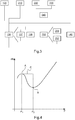
- the memory 51 stores instructions relating to a method for optimizing the noise generated by a hybrid power plant 10 of a rotorcraft in flight, a first block diagram of which is shown in FIG. figure 2 .
- the computer 52 formed for example by a processor or else a logic circuit, allows the execution of the steps of this method.
- This method of optimizing the noise generated by a hybrid power plant 10 of a rotorcraft in flight is executed following an order from a pilot of the rotorcraft 1 requesting a moderation of the noise generated by the hybrid power plant 10 of the rotorcraft 1, for example by means of a first button 31 of the instrument panel 30.
- This method can also be carried out automatically by the management system 5 of the rotorcraft 1.
- a step 120 of determining a power required to be supplied by the hybrid power plant 10 for the flight phase is carried out according to a power model generated for example as a function of the mass of the rotorcraft and of the conditions of temperature and atmospheric pressure outside the rotorcraft.
- a distribution 130 of the power required between the two heat engines 11 and the electric machine 13 is carried out as a function of an objective noise level and of the power required for the flight phase as well as a model of the noise generated. by each heat engine 11 according to an operating parameter P of each heat engine 11.
- This distribution 130 is carried out by means of the control box 53 controlling the two heat engines 11 and a control device 54 controlling the electric machine 13.
- This distribution 130 thus makes it possible to limit the noise generated by the hybrid power plant 10 during the flight phase by reducing the main power supplied by the two engines heaters 11 and to compensate for this reduction in the main power by the first additional power supplied by the electric machine 13 silently.
- the distribution 130 makes it possible to limit the noise generated by the hybrid power plant 10 during the current phase of flight without however reaching the objective noise level, but while preserving the safety of the current phase of flight by ensuring that the The power required is indeed supplied by the hybrid power plant 10.
- the power required is then equal to the sum of the second additional power supplied by each of the two heat engines 11 and of the first additional power supplied by the electric machine 13.
- control device 54 allows regulation of the electric machine 13 so that the electric machine 13 provides the first additional power and, at the same time, the control box 53 allows regulation of the two heat engines 11 in order to reduce their powers. until the main power is reached respectively.
- control device 54 and the control box 53 ensure that the hybrid power plant 10 continuously supplies the required power equal to the sum of the two powers. of the two heat engines 11 and of the first additional power of the electric machine 13.
- the available power of the electric machine 13 is for example equal to a maximum power that the electric machine 13 can provide without degradation of the latter.
- the available power can also be calculated as a function of a quantity of electrical energy available in the source of electrical energy 18 and of a duration of use of this quantity of electrical energy until the source of energy is exhausted electrical energy 18. This available power is thus equal to the power that the electrical machine 13 can supply continuously for the predetermined time until the quantity of electrical energy available in the source of electrical energy 18 is used up.
- the model of the noise generated by each heat engine 11 is defined for example by a curve representing the variation in the sound level of the noise generated by a heat engine 11 and visible on the graph of the figure 4 .
- This curve characterizes the noise generated by a heat engine 11, expressed in decibels (DB), as a function of an operating parameter P of the heat engine.
- An operating parameter P of the heat engine 11 is for example the speed of rotation or an operating temperature of the heat engine 11, a torque supplied by the heat engine 11 or even the power supplied by this heat engine 11.
- This model can also be defined by a set of curves, each curve corresponding for example to different flight conditions, in particular the temperature and atmospheric pressure outside the heat engine, as well as to a given mass of the rotorcraft 1.
- This curve where this set of curves is generated during tests on heat engine benches or during flight tests of rotorcraft 1 prior to its commissioning.
- An update can also be made during the life of rotorcraft 1, depending on the changes and / or the aging of each heat engine 11.
- the curve represented on the graph of the figure 4 comprises two extremes A and B, a first extremum A, forming a maximum, corresponding to a first operating parameter P1, and a second extremum B, forming a minimum, corresponding to a second operating parameter P2.
- the curve decreases between the two extremes A and B and constitutes a zone of decrease C corresponds to values of the operating parameter P included in the interval [P1, P2].
- the control unit 53 controls this at least one heat engine 11 so that the value of the operating parameter P is increased in order to exceed the value P2 and in fact the second extremum B in order to leave the decrease zone C
- the increase in this operating parameter P causes an increase in the power supplied by this at least one heat engine 11. Consequently, the control device 54 controls the electric machine 13 so that the first additional power is reduced so that the hybrid power plant 10 supplies the required power.
- the power supplied by the hybrid power plant 10 may become greater than the power required for the phase of flight of the rotorcraft 1, the power supplied by a heat engine 11 to be increased while the electric machine 13 provides no first additional power. Consequently and if the electric machine 13 is reversible, the electric machine 13 can operate in generator mode in order to optimize the surplus power supplied by the two heat engines and to transform it into electrical energy. Consequently, the hybrid power plant 10 supplies only the power required to the rotors 2, 3 of the rotorcraft 1.
- FIG. 3 A second block diagram of a method for optimizing the noise generated by a hybrid power plant 10 of a rotorcraft is shown in Figure figure 3 .
- this method comprises a step of determining 120 a power required to be supplied by the hybrid power plant 10 for the flight phase and a step 130 of distributing the power required between the two heat engines 11 and the electric machine 13.
- Optional monitoring steps 210-230 may preferably be performed in parallel and in parallel with determining step 120, although they may be performed sequentially.
- a first check 210 makes it possible to monitor the heat engines 11 and to determine whether these heat engines 11 are in a started state, in a stopped state or in a state making it possible to drive the main rotor 2 while respecting a predetermined rotation speed setpoint. .
- This first check 210 is carried out by means of the control box 53.
- the control box 53 then supplies a first electrical signal to the computer 52 of the management system 5 containing the information on the state of each heat engine 11 and possibly of its speed and the state of its parameters P.
- a second control 220 makes it possible to monitor the electric machine 13 and to determine whether the electric machine 13 is at a started state or in a stopped state as well as its mode. This second check 220 is carried out by means of the control device 54. The control device 54 then supplies a second electrical signal to the computer 52 containing information on the state of the electrical machine 13 and possibly its speed.
- a third control 230 makes it possible to monitor the electrical network 20 and to check that the electrical network 20 is capable of supplying the electrical machine 13, in particular by monitoring the electrical power and the electrical energy that the electrical network 20 can deliver as well as the electrical capacity of the source of electrical energy 18.
- This third control 230 is carried out for example by means of, for example, a dedicated control device 55.
- the electric machine 13 is for example started, without transmitting mechanical power to each rotor 2, 3, in anticipation of the realization of a first command 133 of the electric machine 13.
- a fifth control 137 of the electric machine 13 by means of the control device 54 and a sixth control 138 of the two heat engines 11 via the control box 53 are carried out in parallel.
- the control unit 53 controls the two heat engines 11 by reducing the operating parameters P in order to reduce the power supplied by each heat engine 11 while respecting the predetermined rotation speed setpoint for each rotor, especially for the main rotor 2.
- the power of the electric machine 13 When the power of the electric machine 13 reaches the value of the available power, the power of the electric machine 13 also stops increasing in order to stabilize at this available power although the operating parameter P of each heat engine 11 is not equal to the parameter corresponding to the objective noise level.
- the power of the electric machine 13 decreases in order to increase the operating parameter P and make the operating point pass downstream from the second extremum B. If the electric machine 13 does not provide any power, then this electric machine 13 can operate in generator mode, if this electric machine 13 is reversible, in order to transform the excess power supplied by the power plant 10 into electrical energy. This electrical energy is then used by the electrical network 20 of the rotorcraft 1 or else stored in at least one source of electrical energy 18 of the rotorcraft 1.
- the noise optimization method can also include an optional protection step 250 provided with two sub-steps, namely a first sub-step 251 for determining a rotational speed of the main rotor 2 and a second sub-step for decrease 252 in the power of the electric machine 13.
- the first determination sub-step 251 makes it possible to determine a speed of rotation of the main rotor 2 by means of a determination device 12. Then, if the speed of rotation of the main rotor 2 is higher than a predetermined speed, the second power decrease sub-step 252 is performed in order to reduce the power supplied by the electric machine 13 and thereby prevent the main rotor 2 from reaching overspeed.
- This second sub-step 252 of reducing the power of the electric machine 13 can go as far as stopping the electric machine 13.
- the noise optimization method according to the invention can also apply optionally and in parallel with the first control 133 of the electrical machine 13, the third control 230 of the electrical network 20 then the reduction 252 in the power of the electrical system. electrical machine 13 in order to monitor the electrical network 20 during this first command 133.
- the third control 230 detects that the electrical network 20 is no longer able to supply electrically the electrical machine 13 in order to deliver the first additional power, an alert can be transmitted and the reduction 252 in the power of the electrical machine 13 is carried out, possibly until it is stopped depending on the state of the electrical network 20.
- the method for optimizing the noise generated by a rotorcraft 1 can also include an optional step 140 of inhibiting the distribution 130 of the required power.
- the predominant noise source of the rotorcraft 1 may be at least one of the two rotors 2, 3, at least one of the two heat engines 11 or else the mechanical power transmission box 15. Consequently, the inhibition step 140 inhibits the distribution 130 of the power required when the predominant noise source of the rotorcraft 1 is not a heat engine 11, for example during the phases of level cruising flight and d. 'approach.
- the objective noise level that the rotorcraft 1 should preferably not exceed during the flight phase depends on the environment over which the rotorcraft 1 and / or a flight height of the rotorcraft 1 relative to the ground overflown during this phase of flight.
- a rotorcraft 1 comprising several main lift rotors 2, for example a rotorcraft 1 comprising four main lift rotors 2, can apply the method for optimizing the noise generated by a hybrid power plant of a rotorcraft 1 in flight such as described.
Landscapes
- Engineering & Computer Science (AREA)
- Aviation & Aerospace Engineering (AREA)
- Mechanical Engineering (AREA)
- Chemical & Material Sciences (AREA)
- Combustion & Propulsion (AREA)
- General Engineering & Computer Science (AREA)
- Combined Controls Of Internal Combustion Engines (AREA)
- Control Of Vehicle Engines Or Engines For Specific Uses (AREA)
- Structure Of Transmissions (AREA)
Priority Applications (1)
| Application Number | Priority Date | Filing Date | Title |
|---|---|---|---|
| EP21174596.3A EP3889048B1 (de) | 2019-03-29 | 2020-03-23 | Verfahren zur optimierung des lärms, der von einem drehflügelflugzeug im flug erzeugt wird |
Applications Claiming Priority (1)
| Application Number | Priority Date | Filing Date | Title |
|---|---|---|---|
| FR1903327A FR3094314B1 (fr) | 2019-03-29 | 2019-03-29 | Procédé d’optimisation du bruit généré en vol par un giravion. |
Related Child Applications (2)
| Application Number | Title | Priority Date | Filing Date |
|---|---|---|---|
| EP21174596.3A Division EP3889048B1 (de) | 2019-03-29 | 2020-03-23 | Verfahren zur optimierung des lärms, der von einem drehflügelflugzeug im flug erzeugt wird |
| EP21174596.3A Division-Into EP3889048B1 (de) | 2019-03-29 | 2020-03-23 | Verfahren zur optimierung des lärms, der von einem drehflügelflugzeug im flug erzeugt wird |
Publications (2)
| Publication Number | Publication Date |
|---|---|
| EP3715260A1 true EP3715260A1 (de) | 2020-09-30 |
| EP3715260B1 EP3715260B1 (de) | 2022-05-04 |
Family
ID=67999758
Family Applications (2)
| Application Number | Title | Priority Date | Filing Date |
|---|---|---|---|
| EP21174596.3A Active EP3889048B1 (de) | 2019-03-29 | 2020-03-23 | Verfahren zur optimierung des lärms, der von einem drehflügelflugzeug im flug erzeugt wird |
| EP20165034.8A Active EP3715260B1 (de) | 2019-03-29 | 2020-03-23 | Optimierungsverfahren des von einem drehflügelflugzeug im flug erzeugten lärms |
Family Applications Before (1)
| Application Number | Title | Priority Date | Filing Date |
|---|---|---|---|
| EP21174596.3A Active EP3889048B1 (de) | 2019-03-29 | 2020-03-23 | Verfahren zur optimierung des lärms, der von einem drehflügelflugzeug im flug erzeugt wird |
Country Status (6)
| Country | Link |
|---|---|
| US (2) | US11852084B2 (de) |
| EP (2) | EP3889048B1 (de) |
| KR (1) | KR102457613B1 (de) |
| CN (1) | CN111746803B (de) |
| CA (1) | CA3076773C (de) |
| FR (1) | FR3094314B1 (de) |
Cited By (1)
| Publication number | Priority date | Publication date | Assignee | Title |
|---|---|---|---|---|
| FR3155813A1 (fr) * | 2023-11-29 | 2025-05-30 | Safran Helicopter Engines | Procédé de gestion de l’énergie d’un système propulsif hybride d’aéronef |
Families Citing this family (12)
| Publication number | Priority date | Publication date | Assignee | Title |
|---|---|---|---|---|
| US11772807B2 (en) * | 2020-06-18 | 2023-10-03 | Textron Innovations Inc. | Electric distributed anti-torque architecture |
| JP7731301B2 (ja) * | 2022-01-27 | 2025-08-29 | 本田技研工業株式会社 | 航空機用制御システム、航空機用制御方法、および航空機用制御プログラム |
| US12384552B2 (en) * | 2022-03-25 | 2025-08-12 | Pratt & Whitney Canada Corp. | Method of reducing noise of aircraft having hybrid power plants |
| US20230311847A1 (en) * | 2022-03-29 | 2023-10-05 | Pratt & Whitney Canada Corp. | Method and system for reducing noise of hybrid power plant |
| US11698032B1 (en) * | 2022-05-06 | 2023-07-11 | Pratt & Whitney Canada Corp. | Systems and methods for controlling noise in aircraft powered by hybrid-electric gas turbine engines |
| IT202200016215A1 (it) * | 2022-07-29 | 2024-01-29 | Gen Electric | Controllo di sistemi di propulsione e trasmissione completamente elettrici o ibridi-elettrici |
| US12275532B2 (en) | 2022-08-15 | 2025-04-15 | General Electric Company | Gas turbine engine noise reduction |
| US12352181B2 (en) | 2023-01-30 | 2025-07-08 | General Electric Company | Turbine airfoils |
| FR3158094A1 (fr) | 2024-01-08 | 2025-07-11 | Airbus Helicopters | Procédé de pilotage d’une installation motrice hybride pour véhicule et une architecture de pilotage d’une telle installation motrice hybride |
| DE102024106797A1 (de) * | 2024-03-08 | 2025-09-11 | Wipotec Science & Innovation Gmbh | Verfahren und Einrichtung zur Abschätzung der Geräuschentwicklung einer komplexen Vorrichtung, insbesondere einer Inspektionsmaschine |
| US12545418B2 (en) | 2024-07-03 | 2026-02-10 | Pratt & Whitney Canada Corp. | Control assembly for aircraft propulsion systems |
| US12595071B1 (en) | 2024-12-16 | 2026-04-07 | Lockheed Martin Corporation | Parallel hybrid electric vertical takeoff and landing aircraft |
Citations (6)
| Publication number | Priority date | Publication date | Assignee | Title |
|---|---|---|---|---|
| EP2571764A1 (de) | 2010-05-19 | 2013-03-27 | EADS Deutschland GmbH | Hybridantrieb für hubschrauber |
| US20140010652A1 (en) | 2012-07-09 | 2014-01-09 | Mcmaster University | Hybrid powertrain system |
| US8852052B2 (en) | 2011-01-13 | 2014-10-07 | Cummins Inc. | System, method, and apparatus for controlling power output distribution in a hybrid power train |
| US20160362100A1 (en) | 2015-06-12 | 2016-12-15 | GM Global Technology Operations LLC | Method and apparatus for controlling operation of an internal combustion engine for a multi-mode powertrain system |
| FR3039614A1 (fr) | 2015-07-31 | 2017-02-03 | Airbus Helicopters | Installation motrice hybride pour aeronef a voilure tournante bimoteur |
| US20180009542A1 (en) | 2016-07-06 | 2018-01-11 | Martin Kuster | Helicopter hybrid engine system |
Family Cites Families (28)
| Publication number | Priority date | Publication date | Assignee | Title |
|---|---|---|---|---|
| JP4197013B2 (ja) * | 2006-06-28 | 2008-12-17 | トヨタ自動車株式会社 | ハイブリッド車両の制御装置 |
| US8727271B2 (en) * | 2008-01-11 | 2014-05-20 | Ival O. Salyer | Aircraft using turbo-electric hybrid propulsion system |
| DE202008002249U1 (de) * | 2008-02-18 | 2008-04-17 | Dill, Hans-Dieter | Fluggerät mit einer Brennkraftmaschine sowie einem Elektro-Antriebsmotor |
| US8469306B2 (en) * | 2009-01-27 | 2013-06-25 | Ira F. Kuhn, Jr. | Purebred and hybrid electric VTOL tilt rotor aircraft |
| GB0912340D0 (en) * | 2009-07-16 | 2009-08-26 | Rolls Royce Plc | Aircraft power management system |
| DE102010021026A1 (de) * | 2010-05-19 | 2011-11-24 | Eads Deutschland Gmbh | Hybrides Antriebs- und Energiesystem für Fluggeräte |
| FR2987031B1 (fr) * | 2012-02-21 | 2014-10-24 | Eurocopter France | Aeronef a voilure muni d'un rotor arriere, et procede pour optimiser le fonctionnement d'un rotor arriere |
| DE102012209807A1 (de) * | 2012-06-12 | 2013-12-12 | Siemens Aktiengesellschaft | Flugzeug und Verfahren zum Herstellen eines Flugzeugs |
| FR2993727B1 (fr) * | 2012-07-19 | 2017-07-21 | Eurocopter France | Machine electrique reversible pour aeronef |
| FR2994687B1 (fr) * | 2012-08-27 | 2014-07-25 | Eurocopter France | Procede d'assistance d'un pilote d'un aeronef monomoteur a voilure tournante lors d'une phase de vol en autorotation |
| FR2997382B1 (fr) * | 2012-10-29 | 2014-11-21 | Eurocopter France | Procede de gestion d'une panne moteur sur un aeronef multimoteur muni d'une installation motrice hybride |
| FR2998542B1 (fr) | 2012-11-26 | 2015-07-17 | Eurocopter France | Procede et aeronef a voilure tournante muni de trois moteurs |
| US9376983B2 (en) * | 2012-11-30 | 2016-06-28 | Honeywell International Inc. | Operations support systems and methods with acoustics evaluation and control |
| US9193451B2 (en) * | 2013-04-22 | 2015-11-24 | Ival O. Salyer | Aircraft using turbo-electric hybrid propulsion system for multi-mode operation |
| US9169027B2 (en) * | 2013-10-04 | 2015-10-27 | Sikorsky Aircraft Corporation | Electrified rotorcraft |
| FR3030424B1 (fr) * | 2014-12-18 | 2016-12-09 | Renault Sa | Procede de determination de la consommation de carburant d'un groupe motopropulseur thermique de puissance equivalente a celle d'un groupe motopropulseur hybride |
| FR3036235B1 (fr) * | 2015-05-15 | 2018-06-01 | Airbus Helicopters | Procede pour activer un moteur electrique d'une installation hybride d'un aeronef multimoteur et un aeronef |
| KR101667330B1 (ko) * | 2015-07-17 | 2016-10-19 | 주식회사 한국카본 | 하이브리드 전기 추진시스템을 이용하는 수직이착륙 항공기 |
| CN105836141B (zh) * | 2016-04-12 | 2018-01-12 | 电子科技大学 | 一种混合动力直升机驱动机构及驱动方法 |
| CN106564604A (zh) * | 2016-04-13 | 2017-04-19 | 北京天宇新超航空科技有限公司 | 一种油电混合四旋翼动力单元及其控制方法 |
| US10017266B2 (en) * | 2016-09-22 | 2018-07-10 | Top Flight Technologies, Inc. | Power generation and distribution for vehicle propulsion |
| US11149578B2 (en) * | 2017-02-10 | 2021-10-19 | General Electric Company | Propulsion system for an aircraft |
| US10273019B2 (en) * | 2017-03-06 | 2019-04-30 | Rolls-Royce Corporation | Distributed propulsion system power unit control |
| WO2018175349A1 (en) * | 2017-03-19 | 2018-09-27 | Zunum Aero, Inc. | Hybrid-electric aircraft, and methods, apparatus and systems for facilitating same |
| FR3066983B1 (fr) * | 2017-06-06 | 2019-06-28 | Airbus Group Sas | Methode de gestion et architecture de systeme de propulsion hybride |
| US10822101B2 (en) * | 2017-07-21 | 2020-11-03 | General Electric Company | Vertical takeoff and landing aircraft having a forward thrust propulsor |
| CN108216646A (zh) * | 2018-01-10 | 2018-06-29 | 吉林大学 | 一种并联混合动力飞机动力耦合系统及其驱动控制方法 |
| US10906656B2 (en) * | 2018-05-01 | 2021-02-02 | Bell Textron Inc. | Hybrid tiltrotor drive system |
-
2019
- 2019-03-29 FR FR1903327A patent/FR3094314B1/fr active Active
-
2020
- 2020-03-23 EP EP21174596.3A patent/EP3889048B1/de active Active
- 2020-03-23 EP EP20165034.8A patent/EP3715260B1/de active Active
- 2020-03-25 CA CA3076773A patent/CA3076773C/fr active Active
- 2020-03-26 KR KR1020200036821A patent/KR102457613B1/ko active Active
- 2020-03-27 US US16/832,589 patent/US11852084B2/en active Active
- 2020-03-30 CN CN202010235949.5A patent/CN111746803B/zh active Active
-
2023
- 2023-11-15 US US18/509,361 patent/US12479588B2/en active Active
Patent Citations (6)
| Publication number | Priority date | Publication date | Assignee | Title |
|---|---|---|---|---|
| EP2571764A1 (de) | 2010-05-19 | 2013-03-27 | EADS Deutschland GmbH | Hybridantrieb für hubschrauber |
| US8852052B2 (en) | 2011-01-13 | 2014-10-07 | Cummins Inc. | System, method, and apparatus for controlling power output distribution in a hybrid power train |
| US20140010652A1 (en) | 2012-07-09 | 2014-01-09 | Mcmaster University | Hybrid powertrain system |
| US20160362100A1 (en) | 2015-06-12 | 2016-12-15 | GM Global Technology Operations LLC | Method and apparatus for controlling operation of an internal combustion engine for a multi-mode powertrain system |
| FR3039614A1 (fr) | 2015-07-31 | 2017-02-03 | Airbus Helicopters | Installation motrice hybride pour aeronef a voilure tournante bimoteur |
| US20180009542A1 (en) | 2016-07-06 | 2018-01-11 | Martin Kuster | Helicopter hybrid engine system |
Non-Patent Citations (2)
| Title |
|---|
| 1'T CA 0, HELICOPTER NOISE RÉDUCTION TECHNOLOGY, April 2015 (2015-04-01) |
| BRYAN EDWARDSCHARLES COX, REVOLUTIONARY CONCEPTS FOR HELICOPTER NOISE RÉDUCTION — S.I.L.E.N.T. PROGRAM, May 2002 (2002-05-01) |
Cited By (1)
| Publication number | Priority date | Publication date | Assignee | Title |
|---|---|---|---|---|
| FR3155813A1 (fr) * | 2023-11-29 | 2025-05-30 | Safran Helicopter Engines | Procédé de gestion de l’énergie d’un système propulsif hybride d’aéronef |
Also Published As
| Publication number | Publication date |
|---|---|
| CN111746803B (zh) | 2024-07-02 |
| CA3076773A1 (fr) | 2020-09-29 |
| EP3889048B1 (de) | 2024-02-07 |
| FR3094314B1 (fr) | 2021-07-09 |
| EP3715260B1 (de) | 2022-05-04 |
| EP3889048A1 (de) | 2021-10-06 |
| KR102457613B1 (ko) | 2022-10-20 |
| CA3076773C (fr) | 2022-10-25 |
| KR20200115312A (ko) | 2020-10-07 |
| FR3094314A1 (fr) | 2020-10-02 |
| US11852084B2 (en) | 2023-12-26 |
| CN111746803A (zh) | 2020-10-09 |
| US12479588B2 (en) | 2025-11-25 |
| US20240084748A1 (en) | 2024-03-14 |
| US20200309045A1 (en) | 2020-10-01 |
Similar Documents
| Publication | Publication Date | Title |
|---|---|---|
| EP3889048B1 (de) | Verfahren zur optimierung des lärms, der von einem drehflügelflugzeug im flug erzeugt wird | |
| EP2724939B1 (de) | Verfahren zur Steuerung eines Triebwerkausfalls in einem Luftfahrzeug mit mehreren Triebwerken, das mit einer Hybrid-Triebwerksanlage ausgestattet ist | |
| CA2799941C (fr) | Procede automatique de regulation d'un groupe de motorisation d'aeronef, dispositif et aeronef | |
| EP3696084B1 (de) | Optimierungsverfahren des von einem drehflügelflugzeug am boden erzeugten lärms | |
| CA2799138C (fr) | Procede automatique de regulation d'un groupe de motorisation d'aeronef, dispositif et aeronef | |
| EP3967598B1 (de) | Verfahren und vorrichtung zur verwaltung der energie, die von einer hybrid-triebwerksanlage für drehflügelflugzeuge geliefert wird | |
| CA2856655C (fr) | Installation motrice trimoteur regulee pour un aeronef a voilure tournante | |
| EP3109156B1 (de) | Regulierverfahren für eine dreimotorige antriebsanlage für ein drehflügelflugzeug | |
| FR3039614A1 (fr) | Installation motrice hybride pour aeronef a voilure tournante bimoteur | |
| EP2623749B1 (de) | Vorrichtung und Verfahren zur Regelung einer Antriebsanlage, die mindestens über einen Turbomotor verfügt, und Luftfahrzeug | |
| FR3137664A1 (fr) | Ensemble pour une turbomachine hybridée électriquement | |
| CA3240897A1 (fr) | Procede de regulation de la vitesse de rotation d'un propulseur d'un groupe propulsif hybride pour aeronef, en situation de panne du systeme de regulation principal du moteur thermique du groupe propulsif hybrid | |
| WO2025011898A1 (fr) | Procede de commande d'un systeme propulsif d'aeronef ayant des turbomoteurs fonctionnant en parallele et susceptibles d'etre places en veille et aeronef correspondant |
Legal Events
| Date | Code | Title | Description |
|---|---|---|---|
| PUAI | Public reference made under article 153(3) epc to a published international application that has entered the european phase |
Free format text: ORIGINAL CODE: 0009012 |
|
| STAA | Information on the status of an ep patent application or granted ep patent |
Free format text: STATUS: THE APPLICATION HAS BEEN PUBLISHED |
|
| AK | Designated contracting states |
Kind code of ref document: A1 Designated state(s): AL AT BE BG CH CY CZ DE DK EE ES FI FR GB GR HR HU IE IS IT LI LT LU LV MC MK MT NL NO PL PT RO RS SE SI SK SM TR |
|
| AX | Request for extension of the european patent |
Extension state: BA ME |
|
| STAA | Information on the status of an ep patent application or granted ep patent |
Free format text: STATUS: REQUEST FOR EXAMINATION WAS MADE |
|
| 17P | Request for examination filed |
Effective date: 20201106 |
|
| RBV | Designated contracting states (corrected) |
Designated state(s): AL AT BE BG CH CY CZ DE DK EE ES FI FR GB GR HR HU IE IS IT LI LT LU LV MC MK MT NL NO PL PT RO RS SE SI SK SM TR |
|
| STAA | Information on the status of an ep patent application or granted ep patent |
Free format text: STATUS: EXAMINATION IS IN PROGRESS |
|
| 17Q | First examination report despatched |
Effective date: 20210311 |
|
| GRAP | Despatch of communication of intention to grant a patent |
Free format text: ORIGINAL CODE: EPIDOSNIGR1 |
|
| STAA | Information on the status of an ep patent application or granted ep patent |
Free format text: STATUS: GRANT OF PATENT IS INTENDED |
|
| INTG | Intention to grant announced |
Effective date: 20211007 |
|
| GRAJ | Information related to disapproval of communication of intention to grant by the applicant or resumption of examination proceedings by the epo deleted |
Free format text: ORIGINAL CODE: EPIDOSDIGR1 |
|
| STAA | Information on the status of an ep patent application or granted ep patent |
Free format text: STATUS: EXAMINATION IS IN PROGRESS |
|
| INTC | Intention to grant announced (deleted) | ||
| GRAP | Despatch of communication of intention to grant a patent |
Free format text: ORIGINAL CODE: EPIDOSNIGR1 |
|
| STAA | Information on the status of an ep patent application or granted ep patent |
Free format text: STATUS: GRANT OF PATENT IS INTENDED |
|
| INTG | Intention to grant announced |
Effective date: 20220110 |
|
| GRAS | Grant fee paid |
Free format text: ORIGINAL CODE: EPIDOSNIGR3 |
|
| GRAA | (expected) grant |
Free format text: ORIGINAL CODE: 0009210 |
|
| STAA | Information on the status of an ep patent application or granted ep patent |
Free format text: STATUS: THE PATENT HAS BEEN GRANTED |
|
| AK | Designated contracting states |
Kind code of ref document: B1 Designated state(s): AL AT BE BG CH CY CZ DE DK EE ES FI FR GB GR HR HU IE IS IT LI LT LU LV MC MK MT NL NO PL PT RO RS SE SI SK SM TR |
|
| REG | Reference to a national code |
Ref country code: GB Ref legal event code: FG4D Free format text: NOT ENGLISH |
|
| REG | Reference to a national code |
Ref country code: CH Ref legal event code: EP |
|
| REG | Reference to a national code |
Ref country code: AT Ref legal event code: REF Ref document number: 1488829 Country of ref document: AT Kind code of ref document: T Effective date: 20220515 |
|
| REG | Reference to a national code |
Ref country code: IE Ref legal event code: FG4D Free format text: LANGUAGE OF EP DOCUMENT: FRENCH Ref country code: DE Ref legal event code: R096 Ref document number: 602020002933 Country of ref document: DE |
|
| REG | Reference to a national code |
Ref country code: LT Ref legal event code: MG9D |
|
| REG | Reference to a national code |
Ref country code: NL Ref legal event code: MP Effective date: 20220504 |
|
| REG | Reference to a national code |
Ref country code: AT Ref legal event code: MK05 Ref document number: 1488829 Country of ref document: AT Kind code of ref document: T Effective date: 20220504 |
|
| PG25 | Lapsed in a contracting state [announced via postgrant information from national office to epo] |
Ref country code: SE Free format text: LAPSE BECAUSE OF FAILURE TO SUBMIT A TRANSLATION OF THE DESCRIPTION OR TO PAY THE FEE WITHIN THE PRESCRIBED TIME-LIMIT Effective date: 20220504 Ref country code: PT Free format text: LAPSE BECAUSE OF FAILURE TO SUBMIT A TRANSLATION OF THE DESCRIPTION OR TO PAY THE FEE WITHIN THE PRESCRIBED TIME-LIMIT Effective date: 20220905 Ref country code: NO Free format text: LAPSE BECAUSE OF FAILURE TO SUBMIT A TRANSLATION OF THE DESCRIPTION OR TO PAY THE FEE WITHIN THE PRESCRIBED TIME-LIMIT Effective date: 20220804 Ref country code: NL Free format text: LAPSE BECAUSE OF FAILURE TO SUBMIT A TRANSLATION OF THE DESCRIPTION OR TO PAY THE FEE WITHIN THE PRESCRIBED TIME-LIMIT Effective date: 20220504 Ref country code: LT Free format text: LAPSE BECAUSE OF FAILURE TO SUBMIT A TRANSLATION OF THE DESCRIPTION OR TO PAY THE FEE WITHIN THE PRESCRIBED TIME-LIMIT Effective date: 20220504 Ref country code: HR Free format text: LAPSE BECAUSE OF FAILURE TO SUBMIT A TRANSLATION OF THE DESCRIPTION OR TO PAY THE FEE WITHIN THE PRESCRIBED TIME-LIMIT Effective date: 20220504 Ref country code: GR Free format text: LAPSE BECAUSE OF FAILURE TO SUBMIT A TRANSLATION OF THE DESCRIPTION OR TO PAY THE FEE WITHIN THE PRESCRIBED TIME-LIMIT Effective date: 20220805 Ref country code: FI Free format text: LAPSE BECAUSE OF FAILURE TO SUBMIT A TRANSLATION OF THE DESCRIPTION OR TO PAY THE FEE WITHIN THE PRESCRIBED TIME-LIMIT Effective date: 20220504 Ref country code: ES Free format text: LAPSE BECAUSE OF FAILURE TO SUBMIT A TRANSLATION OF THE DESCRIPTION OR TO PAY THE FEE WITHIN THE PRESCRIBED TIME-LIMIT Effective date: 20220504 Ref country code: BG Free format text: LAPSE BECAUSE OF FAILURE TO SUBMIT A TRANSLATION OF THE DESCRIPTION OR TO PAY THE FEE WITHIN THE PRESCRIBED TIME-LIMIT Effective date: 20220804 Ref country code: AT Free format text: LAPSE BECAUSE OF FAILURE TO SUBMIT A TRANSLATION OF THE DESCRIPTION OR TO PAY THE FEE WITHIN THE PRESCRIBED TIME-LIMIT Effective date: 20220504 |
|
| PG25 | Lapsed in a contracting state [announced via postgrant information from national office to epo] |
Ref country code: RS Free format text: LAPSE BECAUSE OF FAILURE TO SUBMIT A TRANSLATION OF THE DESCRIPTION OR TO PAY THE FEE WITHIN THE PRESCRIBED TIME-LIMIT Effective date: 20220504 Ref country code: PL Free format text: LAPSE BECAUSE OF FAILURE TO SUBMIT A TRANSLATION OF THE DESCRIPTION OR TO PAY THE FEE WITHIN THE PRESCRIBED TIME-LIMIT Effective date: 20220504 Ref country code: LV Free format text: LAPSE BECAUSE OF FAILURE TO SUBMIT A TRANSLATION OF THE DESCRIPTION OR TO PAY THE FEE WITHIN THE PRESCRIBED TIME-LIMIT Effective date: 20220504 Ref country code: IS Free format text: LAPSE BECAUSE OF FAILURE TO SUBMIT A TRANSLATION OF THE DESCRIPTION OR TO PAY THE FEE WITHIN THE PRESCRIBED TIME-LIMIT Effective date: 20220904 |
|
| PG25 | Lapsed in a contracting state [announced via postgrant information from national office to epo] |
Ref country code: SM Free format text: LAPSE BECAUSE OF FAILURE TO SUBMIT A TRANSLATION OF THE DESCRIPTION OR TO PAY THE FEE WITHIN THE PRESCRIBED TIME-LIMIT Effective date: 20220504 Ref country code: SK Free format text: LAPSE BECAUSE OF FAILURE TO SUBMIT A TRANSLATION OF THE DESCRIPTION OR TO PAY THE FEE WITHIN THE PRESCRIBED TIME-LIMIT Effective date: 20220504 Ref country code: RO Free format text: LAPSE BECAUSE OF FAILURE TO SUBMIT A TRANSLATION OF THE DESCRIPTION OR TO PAY THE FEE WITHIN THE PRESCRIBED TIME-LIMIT Effective date: 20220504 Ref country code: EE Free format text: LAPSE BECAUSE OF FAILURE TO SUBMIT A TRANSLATION OF THE DESCRIPTION OR TO PAY THE FEE WITHIN THE PRESCRIBED TIME-LIMIT Effective date: 20220504 Ref country code: DK Free format text: LAPSE BECAUSE OF FAILURE TO SUBMIT A TRANSLATION OF THE DESCRIPTION OR TO PAY THE FEE WITHIN THE PRESCRIBED TIME-LIMIT Effective date: 20220504 Ref country code: CZ Free format text: LAPSE BECAUSE OF FAILURE TO SUBMIT A TRANSLATION OF THE DESCRIPTION OR TO PAY THE FEE WITHIN THE PRESCRIBED TIME-LIMIT Effective date: 20220504 |
|
| REG | Reference to a national code |
Ref country code: DE Ref legal event code: R097 Ref document number: 602020002933 Country of ref document: DE |
|
| PLBE | No opposition filed within time limit |
Free format text: ORIGINAL CODE: 0009261 |
|
| STAA | Information on the status of an ep patent application or granted ep patent |
Free format text: STATUS: NO OPPOSITION FILED WITHIN TIME LIMIT |
|
| PG25 | Lapsed in a contracting state [announced via postgrant information from national office to epo] |
Ref country code: AL Free format text: LAPSE BECAUSE OF FAILURE TO SUBMIT A TRANSLATION OF THE DESCRIPTION OR TO PAY THE FEE WITHIN THE PRESCRIBED TIME-LIMIT Effective date: 20220504 |
|
| 26N | No opposition filed |
Effective date: 20230207 |
|
| PG25 | Lapsed in a contracting state [announced via postgrant information from national office to epo] |
Ref country code: SI Free format text: LAPSE BECAUSE OF FAILURE TO SUBMIT A TRANSLATION OF THE DESCRIPTION OR TO PAY THE FEE WITHIN THE PRESCRIBED TIME-LIMIT Effective date: 20220504 |
|
| P01 | Opt-out of the competence of the unified patent court (upc) registered |
Effective date: 20230530 |
|
| PG25 | Lapsed in a contracting state [announced via postgrant information from national office to epo] |
Ref country code: MC Free format text: LAPSE BECAUSE OF FAILURE TO SUBMIT A TRANSLATION OF THE DESCRIPTION OR TO PAY THE FEE WITHIN THE PRESCRIBED TIME-LIMIT Effective date: 20220504 |
|
| REG | Reference to a national code |
Ref country code: CH Ref legal event code: PL |
|
| REG | Reference to a national code |
Ref country code: BE Ref legal event code: MM Effective date: 20230331 |
|
| PG25 | Lapsed in a contracting state [announced via postgrant information from national office to epo] |
Ref country code: LU Free format text: LAPSE BECAUSE OF NON-PAYMENT OF DUE FEES Effective date: 20230323 |
|
| REG | Reference to a national code |
Ref country code: IE Ref legal event code: MM4A |
|
| PG25 | Lapsed in a contracting state [announced via postgrant information from national office to epo] |
Ref country code: LI Free format text: LAPSE BECAUSE OF NON-PAYMENT OF DUE FEES Effective date: 20230331 Ref country code: IE Free format text: LAPSE BECAUSE OF NON-PAYMENT OF DUE FEES Effective date: 20230323 Ref country code: CH Free format text: LAPSE BECAUSE OF NON-PAYMENT OF DUE FEES Effective date: 20230331 |
|
| PG25 | Lapsed in a contracting state [announced via postgrant information from national office to epo] |
Ref country code: BE Free format text: LAPSE BECAUSE OF NON-PAYMENT OF DUE FEES Effective date: 20230331 |
|
| PG25 | Lapsed in a contracting state [announced via postgrant information from national office to epo] |
Ref country code: BG Free format text: LAPSE BECAUSE OF FAILURE TO SUBMIT A TRANSLATION OF THE DESCRIPTION OR TO PAY THE FEE WITHIN THE PRESCRIBED TIME-LIMIT Effective date: 20220504 |
|
| GBPC | Gb: european patent ceased through non-payment of renewal fee |
Effective date: 20240323 |
|
| PG25 | Lapsed in a contracting state [announced via postgrant information from national office to epo] |
Ref country code: BG Free format text: LAPSE BECAUSE OF FAILURE TO SUBMIT A TRANSLATION OF THE DESCRIPTION OR TO PAY THE FEE WITHIN THE PRESCRIBED TIME-LIMIT Effective date: 20220504 |
|
| PG25 | Lapsed in a contracting state [announced via postgrant information from national office to epo] |
Ref country code: GB Free format text: LAPSE BECAUSE OF NON-PAYMENT OF DUE FEES Effective date: 20240323 |
|
| PG25 | Lapsed in a contracting state [announced via postgrant information from national office to epo] |
Ref country code: GB Free format text: LAPSE BECAUSE OF NON-PAYMENT OF DUE FEES Effective date: 20240323 |
|
| PG25 | Lapsed in a contracting state [announced via postgrant information from national office to epo] |
Ref country code: CY Free format text: LAPSE BECAUSE OF FAILURE TO SUBMIT A TRANSLATION OF THE DESCRIPTION OR TO PAY THE FEE WITHIN THE PRESCRIBED TIME-LIMIT; INVALID AB INITIO Effective date: 20200323 |
|
| PG25 | Lapsed in a contracting state [announced via postgrant information from national office to epo] |
Ref country code: HU Free format text: LAPSE BECAUSE OF FAILURE TO SUBMIT A TRANSLATION OF THE DESCRIPTION OR TO PAY THE FEE WITHIN THE PRESCRIBED TIME-LIMIT; INVALID AB INITIO Effective date: 20200323 |
|
| PG25 | Lapsed in a contracting state [announced via postgrant information from national office to epo] |
Ref country code: TR Free format text: LAPSE BECAUSE OF FAILURE TO SUBMIT A TRANSLATION OF THE DESCRIPTION OR TO PAY THE FEE WITHIN THE PRESCRIBED TIME-LIMIT Effective date: 20220504 |
|
| PGFP | Annual fee paid to national office [announced via postgrant information from national office to epo] |
Ref country code: DE Payment date: 20260319 Year of fee payment: 7 |
|
| PGFP | Annual fee paid to national office [announced via postgrant information from national office to epo] |
Ref country code: IT Payment date: 20260324 Year of fee payment: 7 |
|
| PGFP | Annual fee paid to national office [announced via postgrant information from national office to epo] |
Ref country code: FR Payment date: 20260320 Year of fee payment: 7 |