EP3715267A1 - Station de travail pour une machine d'emballage - Google Patents
Station de travail pour une machine d'emballage Download PDFInfo
- Publication number
- EP3715267A1 EP3715267A1 EP20155990.3A EP20155990A EP3715267A1 EP 3715267 A1 EP3715267 A1 EP 3715267A1 EP 20155990 A EP20155990 A EP 20155990A EP 3715267 A1 EP3715267 A1 EP 3715267A1
- Authority
- EP
- European Patent Office
- Prior art keywords
- rotor
- gear
- working unit
- drive
- work station
- Prior art date
- Legal status (The legal status is an assumption and is not a legal conclusion. Google has not performed a legal analysis and makes no representation as to the accuracy of the status listed.)
- Granted
Links
Images






Classifications
-
- B—PERFORMING OPERATIONS; TRANSPORTING
- B65—CONVEYING; PACKING; STORING; HANDLING THIN OR FILAMENTARY MATERIAL
- B65B—MACHINES, APPARATUS OR DEVICES FOR, OR METHODS OF, PACKAGING ARTICLES OR MATERIALS; UNPACKING
- B65B9/00—Enclosing successive articles, or quantities of material, e.g. liquids or semiliquids, in flat, folded, or tubular webs of flexible sheet material; Subdividing filled flexible tubes to form packages
- B65B9/02—Enclosing successive articles, or quantities of material between opposed webs
- B65B9/04—Enclosing successive articles, or quantities of material between opposed webs one or both webs being formed with pockets for the reception of the articles, or of the quantities of material
-
- B—PERFORMING OPERATIONS; TRANSPORTING
- B26—HAND CUTTING TOOLS; CUTTING; SEVERING
- B26D—CUTTING; DETAILS COMMON TO MACHINES FOR PERFORATING, PUNCHING, CUTTING-OUT, STAMPING-OUT OR SEVERING
- B26D5/00—Arrangements for operating and controlling machines or devices for cutting, cutting-out, stamping-out, punching, perforating, or severing by means other than cutting
- B26D5/08—Means for actuating the cutting member to effect the cut
- B26D5/14—Crank and pin means
-
- B—PERFORMING OPERATIONS; TRANSPORTING
- B26—HAND CUTTING TOOLS; CUTTING; SEVERING
- B26F—PERFORATING; PUNCHING; CUTTING-OUT; STAMPING-OUT; SEVERING BY MEANS OTHER THAN CUTTING
- B26F1/00—Perforating; Punching; Cutting-out; Stamping-out; Apparatus therefor
-
- B—PERFORMING OPERATIONS; TRANSPORTING
- B65—CONVEYING; PACKING; STORING; HANDLING THIN OR FILAMENTARY MATERIAL
- B65B—MACHINES, APPARATUS OR DEVICES FOR, OR METHODS OF, PACKAGING ARTICLES OR MATERIALS; UNPACKING
- B65B65/00—Details peculiar to packaging machines and not otherwise provided for; Arrangements of such details
- B65B65/02—Driving gear
-
- B—PERFORMING OPERATIONS; TRANSPORTING
- B29—WORKING OF PLASTICS; WORKING OF SUBSTANCES IN A PLASTIC STATE IN GENERAL
- B29C—SHAPING OR JOINING OF PLASTICS; SHAPING OF MATERIAL IN A PLASTIC STATE, NOT OTHERWISE PROVIDED FOR; AFTER-TREATMENT OF THE SHAPED PRODUCTS, e.g. REPAIRING
- B29C51/00—Shaping by thermoforming, i.e. shaping sheets or sheet like preforms after heating, e.g. shaping sheets in matched moulds or by deep-drawing; Apparatus therefor
- B29C51/18—Thermoforming apparatus
-
- B—PERFORMING OPERATIONS; TRANSPORTING
- B29—WORKING OF PLASTICS; WORKING OF SUBSTANCES IN A PLASTIC STATE IN GENERAL
- B29C—SHAPING OR JOINING OF PLASTICS; SHAPING OF MATERIAL IN A PLASTIC STATE, NOT OTHERWISE PROVIDED FOR; AFTER-TREATMENT OF THE SHAPED PRODUCTS, e.g. REPAIRING
- B29C51/00—Shaping by thermoforming, i.e. shaping sheets or sheet like preforms after heating, e.g. shaping sheets in matched moulds or by deep-drawing; Apparatus therefor
- B29C51/26—Component parts, details or accessories; Auxiliary operations
- B29C51/30—Moulds
- B29C51/38—Opening, closing or clamping means
Definitions
- the invention relates to a work station for a packaging machine, with a frame supported on the floor, at least one working unit with a work tool, and at least one lifting mechanism supported on the frame, with which the working unit can be raised and lowered relative to the frame for performing a working stroke.
- the packaging machine is in particular a thermoforming packaging machine.
- Packaging machines with which packaging is produced, in particular from material webs such as film webs, and at the same time filled with products to be packaged, such as food, perform a multitude of work steps at several different work stations, which are distributed in a transport or longitudinal direction of the packaging machine are.
- depressions also known as depressions are formed in a lower film.
- an upper film previously applied to the lower film is bonded to the lower film, which is typically done by a thermal process known as sealing.
- the packs are separated at work stations located downstream of the sealing station. This is done in particular by cutting or punching tools. Further work stations, which are arranged in particular upstream of the sealing station, can serve to include the lower film and / or the upper film and any intermediate films provided To provide perforations, which are used, for example, in the sealing station for evacuating and gassing the packaging.
- the work stations of a packaging machine typically include at least one work tool, which is raised to perform a work step in order to interact with a counter-tool.
- the counter-tool can be a simple abutment or a tool that performs an additional work function.
- the counter-tool can also perform a lifting movement to carry out a work step.
- the respective working width of the packaging machine i.e. its dimension measured transversely to the transport direction of the material webs and thus transversely to the working or longitudinal direction of the packaging machine, provides a corresponding installation space for the workstations
- the installation space available in the transport or longitudinal direction is for the The lifting mechanism of the workstation is regularly very limited.
- the object of the invention is to develop a workstation of the type mentioned at the outset in such a way that, with as little space as possible, especially in The longitudinal direction of the working stroke of the working unit can be controlled as flexibly as possible, while at the same time it must be ensured that there is sufficient stability in order to be able to transmit the greatest possible forces.
- the lifting mechanism comprises a drive, a rotor and a gear, the rotor being rotatable by means of the drive for lifting the working unit in one direction and for lowering the working unit in the opposite direction, the gearing on the input side with the Rotor and is connected on the output side to the working unit, and wherein the drive is a rotary drive with a rotating drive element, in particular a rotor or an output shaft of an electric motor, the rotary movement of the output element being transmitted to the rotor.
- the drive concept according to the invention in which a rotary drive sets a rotor in rotation, the rotational movement of which is transmitted to the gearbox, in which linear drives are consequently avoided, allows different gearbox concepts that can be adapted to the respective requirements, but which in any case save space and in one can be designed to transmit large forces in a sufficiently stable manner.
- the drive comprises a servomotor.
- a servomotor allows a flexibly controlled movement of the lifting mechanism and thus of the working unit.
- the speed of the working unit during the working stroke can be varied as required.
- Dependent on a fundamentally arbitrary speed profile can thus be specified for the working unit for the respective application.
- the lifting mechanism preferably extends in a transverse direction and in a longitudinal direction, the extent of the lifting mechanism in the longitudinal direction being smaller than in the transverse direction.
- the extension in the longitudinal direction is less than 1/2 or less than 1/3 or less than 1/4 or less than 1/5 of the extension in the transverse direction.
- the lifting mechanism is preferably contained in an imaginary cuboid space element which has a width measured in the transverse direction and a length measured in the longitudinal direction, the length being less than 200 mm, preferably less than 140 mm. In this way it can be achieved that the lifting mechanism does not require more space in the longitudinal direction than a respective package that is produced in a packaging machine or filled with a product to be packaged, in which the work station is integrated.
- the gear of the lifting mechanism is in particular a planar or spatial coupling gear.
- Such transmissions can be constructed in many ways and thus adapted to different requirements. To this extent, the invention allows recourse to proven design principles.
- the transmission preferably comprises at least one toggle lever arrangement, in particular a double toggle lever arrangement.
- the lifting mechanism according to the invention can make use of the fundamentally known advantages of the toggle lever concept. It is particularly advantageous that in the extended position, when the force acting on the transmission is at its maximum, it cannot be absorbed by the drive but by the transmission elements.
- the transmission comprises two, preferably structurally identical, transmission parts which are acted upon in parallel by means of the rotor.
- These two transmission parts are arranged in the same position in particular in relation to the longitudinal direction and are spaced apart from one another in the transverse direction. Consequently, it can be provided in an advantageous embodiment that the rotor is arranged between the two transmission parts, viewed in the transverse direction of the lifting mechanism.
- the rotor is preferably arranged centrally between the two transmission parts. A structure that is symmetrical in this respect can consequently be implemented, which uses the available width and at the same time ensures that the working unit is applied evenly.
- the two gear parts are preferably connected to the rotor at different entry points, which preferably lie on the same radius with respect to an axis of rotation of the rotor and are offset from one another by 180 °.
- the transmission comprises two, preferably structurally identical, transmission parts or not, it can generally be provided according to an exemplary embodiment that the lifting mechanism has a symmetrical structure with respect to the axis of rotation of the rotor.
- the gearbox or each of a plurality of gearbox parts forming the gearbox comprises at least one link articulated to the rotor, at least one rocker articulated to the frame and at least one link articulated to the working unit.
- the swing arm provides support on the frame.
- the rotor can - depending on the specific design of the lifting mechanism - be arranged stationary with respect to the frame or it can participate in the lifting movement relative to the frame.
- the linkage is articulated to the rotor in particular at a point spaced apart from the axis of rotation of the rotor.
- the link connected to the rotor can have a curved course.
- the rocker arm and the coupling can have the same length, but this is not mandatory.
- the maximum stroke of the working unit corresponds to a rotation of the rotor by no more than 180 °.
- the rotor can be used to simultaneously act on two links which are articulated at different points and which are each assigned to one of two gear parts forming the gear, in particular structurally identical.
- the drive preferably interacts with the rotor via at least one belt, in particular via at least one toothed belt. This increases the flexibility in the positioning of a drive motor forming the drive or belonging to the drive and the rotor.
- the drive element of the drive in particular a rotor or an output shaft of an electric motor forming the drive or belonging to the drive, does not have to interact directly with the rotor via precisely one drive belt.
- One or more drive shafts can be interposed.
- a first intermediate drive shaft which extends in the longitudinal direction, can interact at a first point in the longitudinal direction via a drive belt with the drive element of the drive, and at a second point axially spaced in the longitudinal direction, either the rotor or a further intermediate drive is possible by means of a further drive belt Pressurize the drive shaft.
- the installation space available in the longitudinal direction can be used to transmit the drive movement of the drive element of the drive to the rotor, which in turn allows greater flexibility in the arrangement of the individual components of the lifting mechanism.
- the drive comprises a drive motor with an output shaft which forms the input of a gear unit assigned to the motor, the output shaft of which runs perpendicular to the output shaft of the motor.
- the output shaft of the motor can run perpendicular to the longitudinal direction of the work station, and the output shaft of the transmission part can extend in the longitudinal direction. This is particularly advantageous when the axis of rotation of the rotor also extends in the longitudinal direction.
- the transmission of the rotary movement of the drive motor to the rotor can thereby be designed to be particularly compact with minimal space requirement in the longitudinal direction and by utilizing the installation space available in the transverse direction.
- the drive and the rotor can either both be arranged stationary with respect to the frame or jointly perform a lifting movement relative to the frame.
- the working unit is carried exclusively by the lifting mechanism. It is consequently not necessary to support the working unit directly on the frame.
- the gear is a coupling gear, the horizontal joint axes of which run parallel to the axis of rotation of the rotor.
- the joint axes of the coupling mechanism and the axis of rotation of the rotor can consequently be oriented parallel to one another and in the longitudinal direction of the work station.
- a link or partial link of the transmission articulated to the rotor at a point spaced apart from the axis of rotation of the rotor has a curved profile.
- the transmission comprises two identical transmission parts which are acted upon in parallel by means of the rotor and each comprise a link articulated to the rotor, a rocker articulated to the frame and a coupling articulated to the working unit, the link, the rocker arm and the coupling are connected to one another in an articulated manner at a common point, which is forcibly guided on the frame along a preferably straight and in particular horizontal path.
- the rotor can be arranged stationary with respect to the frame, the link comprising at least two articulated part links, of which one is articulated to the rotor and the other is articulated to another component of the transmission.
- the transmission is a spatial coupling mechanism in which the joint axes between the working unit and coupling, between frame and rocker and between coupling and rocker run horizontally, in which the axis of rotation of the rotor runs vertically and at which the links are connected to the rotor on the one hand and to the coupling or the rocker on the other hand by a ball joint.
- Such a concept has the advantage, among other things, that the drive element of the drive can interact directly with the rotor or even form a component part of the rotor.
- the drive is a rotary drive with a rotating drive element, in particular a rotor or an output shaft of an electric motor, the rotational movement of the drive element being transmitted to the rotor, and the axis of rotation of the drive element running parallel to the axis of rotation of the rotor and in particular coincides with the axis of rotation of the rotor.
- the rotor can be placed directly on the output shaft of an electric motor.
- the rotor and the drive motor can thus be arranged vertically one below the other and thus in particular without offset in the longitudinal direction, which means optimal use of the installation space available in the longitudinal direction.
- the transmission comprises two, preferably structurally identical, transmission parts which are acted upon in parallel by means of the rotor, the rotor comprising two rotor parts which can be rotated simultaneously and in opposite directions by means of the drive and which have coincident axes of rotation, and the one rotor part and the one transmission part and the other rotor part acts on the other gear part.
- This division of the rotor into rotor parts that can rotate in opposite directions opens up further leeway in the construction and accommodation of the lifting mechanism in an installation space that is primarily restricted in the longitudinal direction.
- each gear part includes a link, with one link articulated to one rotor part and the other link to the other rotor part in the space between the two rotor parts is, and wherein the two links extend out of the space and are each articulated outside the space with a different component of the transmission.
- a common drive can be provided for the two rotor parts, which simultaneously causes both rotor parts to rotate by means of a common belt.
- the belt preferably forms two loops, one of which runs around a drive element of the drive and the other around a deflection, the belt forming a partial loop between the loops for both rotor parts.
- the drive is a rotary drive with a rotating drive element, in particular a rotor or an output shaft of an electric motor, the rotary movement of the drive element being transmitted to the rotor is, and wherein the axis of rotation of the drive member is perpendicular to the axis of rotation of the rotor and in particular horizontally.
- the gear can be designed as a Watt's planetary gear.
- Such a transmission is characterized by a particularly simple structure, which is therefore particularly well suited for a work station of the type in question here, since this structure can be arranged in the work station in such a way that little installation space is required in the longitudinal direction.
- two working units are provided, namely a lower working unit and an upper working unit, which can be moved simultaneously and in opposite directions with the lifting mechanism in such a way that when one working unit is raised, the other working unit is lowered, and vice versa.
- a single drive is required to move the two working units simultaneously.
- the two working units can be moved between an open position and a closed position, the working units jointly undertaking a processing with respective tools when moving into the closed position or when reaching the closed position, in particular cutting, punching, punching, forming, deep drawing or Seal.
- the transmission connected to the rotor on the input side is connected on the output side to both the one working unit and the other working unit, in particular at two different points.
- the two working units can consequently be acted upon simultaneously by means of a single gear.
- the gearbox comprises two gearbox sections, of which one gearbox section is connected on the input side to the rotor and on the output side with one, in particular the lower, working unit, and of which the other gearbox section is connected on the input side with one gearbox section and on the output side with the other, in particular the upper, working unit connected is.
- the movement of the other working unit can consequently be derived from the gear section of the one working unit. It is therefore not necessary to connect gear sections of both working units to the rotor.
- the gear sections of the two working units are not connected in parallel with respect to their common drive, in particular on the rotor, but in series.
- the two gear sections each include at least one planar or one spatial coupling gear.
- the two gear sections each include at least one toggle lever arrangement, in particular a double toggle lever arrangement each.
- the two gear sections each comprise two, preferably structurally identical, gear parts that are acted upon in parallel, the gear parts of one gear section being acted upon in parallel by means of the rotor and the gear parts of the other gear section each by means of a gear part of one gear section are acted upon, wherein in particular the two gear parts of the other gear section are connected to one another by a rigid connecting piece, which is preferably connected in an articulated manner to a coupling of the gear part on both gear parts.
- the two gear sections each include at least one link, at least one rocker arm articulated to the frame and at least one articulated coupling with the respective working unit, the articulated connection between working unit and coupling above the articulated coupling preferably for the lower working unit Connection between frame and rocker is and for the upper work unit the articulated connection between the work unit and paddock below the articulated Connection between frame and rocker is, or vice versa.
- the work station can alternatively have at least two lifting mechanisms spaced apart in a longitudinal direction according to at least one of the configurations explained above, i.e. each provided with a drive, a rotor and a gear, wherein the drives of the lifting mechanisms can be operated in a synchronized manner, i.e. in particular can be controlled synchronously, to raise and lower the working unit together.
- the working unit comprises, for example, a molding tool, a deep-drawing tool or a sealing tool that has an extension in the longitudinal direction that is in particular significantly greater than the length of a package
- a work station can be arranged by synchronous control of, for example, two lifting mechanisms that are spaced apart in the longitudinal direction are raised and lowered.
- the invention also relates to a packaging machine, in particular a thermoforming packaging machine, with at least one work station according to the invention.
- the work station is preferably arranged downstream of a sealing station of the packaging machine in a working direction of the packaging machine that corresponds to the above-mentioned longitudinal direction, the work station for processing a material web, in particular a film web, for processing a packaging or part of a packaging, or for separating packaging educated.
- the invention also relates to the use of a work station according to the invention in a packaging machine, in particular a deep-drawing packaging machine, for processing a material web, in particular a film web, for processing a packaging or part of a packaging, or for separating packaging.
- a packaging machine in particular a deep-drawing packaging machine, for processing a material web, in particular a film web, for processing a packaging or part of a packaging, or for separating packaging.
- the processing mentioned includes, in particular, cutting, punching, punching, shaping, deep drawing or sealing.
- the invention also relates to the use of a servo motor designed as a rotary drive as a drive in a lifting mechanism of the type described in the present disclosure.
- the workstations according to the invention are designed to be used in a packaging machine, in particular in a deep-drawing packaging machine.
- FIG. 7 a possible configuration of such a packaging machine is explained, in which different work stations are only indicated schematically. These work stations can be designed in the manner according to the invention, ie the lifting mechanism according to the invention can be used in one or more of these work stations.
- the packaging machine shown operating in a transport direction T (which here corresponds to the longitudinal direction) comprises a machine frame 47.
- a transport chain 27 shown here only schematically at the upstream end of the machine, is guided in each case.
- the two transport chains 27 together form a transport device for a lower film 23 withdrawn from a supply roll 23a.
- the machine comprises a plurality of workstations following one another in the transport direction T, namely a forming station 11, also referred to as a deep-drawing or thermoformer, an introduction station 13 for products 10 to be packaged, a feed station 14 for an upper film 25 drawn off a supply roll 25a, a labeling station 16, a transverse cutting station 17 and a longitudinal cutting station 19.
- the products 10 to be packaged are, for example, food products, here in the form of so-called portions, each comprising several slices, which have been previously removed from a loaf-shaped or bar-shaped food product by means of a food slicer (not shown). Sausage, cheese, ham or meat have been separated.
- the operation of the packaging machine is controlled by a central control device 41, which is also responsible for a regulation which will be discussed in more detail below.
- the packaging machine is provided with an operating device 45 which e.g. comprises a touch screen on which all necessary information can be displayed to an operator and the operator can make all necessary settings before and during the operation of the machine.
- depressions 29, also referred to as depressions are formed in each case in a deep-drawing process in the lower film 23.
- the aforementioned portions 10 are inserted into these depressions 29 at the introduction station 13.
- the introduction station 13 here comprises a so-called insert, of which two endless conveyor belts 13a, 13b are shown.
- the introduction station 13 can comprise a robot 50, also shown schematically here, e.g. in the form of a so-called “picker”, which can be designed as a delta robot with a gripper 52, which comprises two shovels each holding a portion 10 together.
- robots and their use in the handling of foodstuffs, in particular when inserting portions into recesses in packaging are fundamentally known to the person skilled in the art, which is why further explanations are not required here.
- the sealing station 15 which comprises an upper tool 15a and a lower tool 15b.
- the upper film 25 and the lower film 23 are connected to one another by means of these tools 15a, 15b.
- the depressions 29 and thus the packaging 21 formed by the upper film 25 and lower film 23 are closed.
- Sealing points 43 running transversely to the transport direction T also referred to as sealing seams, are indicated schematically.
- the packs 21 are still connected by the upper film 25 and the lower film 23, so they still have to be separated.
- the packs 21 are provided with labels 51 before they are separated at the labeling station 16.
- one or more labeling stations 16 can be positioned downstream of the separating stations 17, 19.
- one or more workstations can be provided on which the packaging 21 is provided with one or more imprints 53.
- Further work stations can be provided downstream of the separating stations 17, 19, for example a scale for checking the weight of the packaging 21.
- FIG. 7 A variety of in Fig. 7
- the packaging machine can be provided with measuring devices, not shown here, at locations not designated in more detail.
- An upper and a lower measuring device can each be provided immediately behind the forming station 11.
- An upper and a lower measuring device can likewise be arranged in connection with the introduction station 13.
- Another measuring device can be assigned to the feed station 14 for the upper film 25.
- An upper and a lower measuring device can in turn be arranged directly behind the sealing station 15.
- An upper and a lower measuring device can also be connected to the labeling station 16.
- a measuring device can be arranged downstream of the transverse cutting station 17 and a further measuring device can be arranged downstream of the longitudinal cutting station 19.
- a last measuring device in the transport direction T which is not assigned to any of the work stations mentioned, can additionally be provided in order to carry out a measurement of the finished packaging 21 depending on the respective application.
- the packaging machine can have a smaller or a larger number of measuring devices.
- one or more measuring devices are not present behind each work station, but only behind some of the work stations.
- a format set here generally designates a group of items, here in particular both portions 10 and depressions 29 or packaging 21, which are handled as a whole - that is, format sets - and differ from one another in particular by the number and spacing of items in the longitudinal and transverse directions.
- a format set of 3 x 4 (3 in the transverse direction and 4 in the longitudinal direction) recesses 29 are formed in the forming station 11 per work cycle of the packaging machine, at the introduction station 13 a format set of 3 x 4 correspondingly arranged products 10 are introduced into a respective format set of recesses 21 and at the sealing station 15, a respective format set of 3 ⁇ 4 recesses 29 filled with products 10 are sealed.
- the packaging machine can be operated in such a way that it is possible to record, analyze and eliminate or reduce packaging errors.
- the aforementioned measuring devices are used for this purpose.
- the different concepts that are possible in this context do not need to be discussed in more detail at this point.
- the work stations can be provided with an actuator 11c, 15c, 17a or 19a for such a change in position.
- This actuator can be automatically controlled by the control device 41 or manually operated or controlled by an operator.
- a work station according to the invention is to be movable in the transport direction, this may have to be taken into account in a suitable manner when building and / or integrating the lifting mechanism according to the invention.
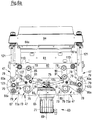
- the drive 63 comprises a servomotor 71, the output shaft 69 of which is shown only by a dashed line and is coupled to a gear unit 72 flanged to the motor 71 in such a way that the output shaft 69 of the motor 71 forms the input element of the gear unit 72.
- the gear unit 72 is designed in such a way that a drive shaft 105, which forms the output member of the gear unit 72, runs with an axis of rotation 107 perpendicular to the output shaft 69 of the motor 71.
- the frame of the workstation includes two guide plates 101 spaced apart in the longitudinal direction T, of which in FIG Fig. 1a and 1b only the rear guide plate 101 is shown here.
- the drive 63 is arranged in a stationary manner on the frame 47 via the gear unit 72.
- the rotary movement of the drive shaft 105 is transmitted via a belt drive, which is only partially shown here, to a rotor 65 whose axis of rotation 75 runs parallel to the drive shaft 105 and thus also parallel to the longitudinal direction T and thus in the horizontal direction.
- the belt drive mentioned in Fig. 1a and 1b a drive shaft 109 and a toothed belt 77 coupling the drive shaft 109 to the rotor 75 are shown.
- the drive shaft 109 on the back of the guide plate 101 is connected to the drive shaft 105 of the gear unit 72 via a further toothed belt.
- a working unit 61 here represented by a beam extending in the transverse direction Q, which is provided with one or more working tools (not shown), e.g. a punching or perforating tool, can be raised and lowered in the vertical direction to perform a working movement.
- the upward movement of the working unit 61 is also referred to as the working stroke.
- the servomotor 71 is controlled in the respective direction of rotation, the resulting rotational movement of the rotor 65 being transmitted to the working unit 61 by means of a gear 67, which here has two gear parts 73 which are spaced apart in the transverse direction Q and have the same structure comprises, between which the rotor 65 is arranged centrally.
- This gear 67 which includes the two gear parts 73, is a planar coupling gear which is acted upon by the central rotor 65, which moves vertically during the working stroke.
- All joint axes 79 of each gear part 73 run horizontally and thus likewise parallel to the axis of rotation 75 of the rotor 65 and to the axis of rotation 107 of the output shaft 105 of the gear unit 72.
- Each gear part 73 comprises a toggle lever arrangement of two parallel straight couplings 85, two parallel curved links 81 and a straight rocker 83.
- the gear thus comprises a double toggle lever arrangement, the toggle levers of the two gear parts 73 each moving during the working stroke move outwardly away from the axis of rotation 75 of the rotor 65 and thus in opposite directions.
- the rocker 83 is articulated to the frame 47 at one end (cf. the configuration according to FIGS Figures 1c-1e ) and at the other end articulated to the link arrangement 81 and the coupling arrangement 85.
- the three components of the coupling gear, namely rocker arm 83, link 81 and coupling 85, are in the embodiment of Fig. 1 , so in both configurations according to Fig. 1a and 1b on the one hand and Figures 1c-1e on the other hand, articulated to one another at a common point 87, which moves horizontally during the working stroke.
- the rocker 83 is located, viewed in the longitudinal direction T, between the two couplings 85, which in turn are located between the two links 81.
- the two links 81 are each articulated at their other end to one of the two end faces of the rotor 65, specifically at a point spaced apart in the radial direction from the axis of rotation 75 of the rotor 65.
- the two links 81 of the other transmission part 73 engage at each diametrically opposite point with respect to the axis of rotation 75 of the rotor 65.
- Fig. 1a shows, in which the working unit 61 is shown in its lowered position, the links 81 of the two transmission parts 73 are curved in such a way that the two toggle lever assemblies assume a compact overall configuration in this bent state.
- the two coupling arrangements 85 of the transmission parts 73 are each articulated to the working unit 61 at points spaced apart in the transverse direction Q.
- both gear parts 73 can consequently be acted upon synchronously in order to act in the same way on the working unit 61 at two points spaced apart in the transverse direction.
- a force to be transmitted by means of the working unit 71 can consequently be applied to a counter-tool or an abutment, evenly distributed in the transverse direction Q, with a material web to be processed, for example a film web of a thermoforming packaging machine to be cut or punched in between.
- FIG Figure 1b The working position with the working unit 61 raised to the maximum and consequently extended toggle lever arrangements is shown in FIG Figure 1b , in which only the axes of rotation are designated for the sake of clarity, namely the horizontal joint axes 79 of the coupling gear formed by the two gear parts 73, the axis of rotation 75 of the rotor 65 and the axis of rotation 107 of the drive shaft 105 of the gear unit 72 connected to the servo motor 71.
- Figure 1c shows that the work station has a length measured in the working or transport direction T, which is referred to here as the longitudinal direction, which is significantly smaller than the width measured in the transverse direction Q, which corresponds to the working width of the respective packaging machine.
- the workstation according to the invention can consequently be built very narrow.
- rollers 113 which are each attached to the outside of the two guide plates 101 and thus the under among other things, guide the guide plates 101 and the rotor 65 comprehensive arrangement when raising and lowering the working unit 61 in the vertical direction.
- elongated holes formed in the guide plates 101 and serving as guide tracks 89 remain in a horizontal orientation during the up and down movement.
- the drive 63 is shown with an inclined output shaft 69.
- the gear unit 72 is provided with a horizontally running drive shaft 105, so that the drive 63 is opposite Fig. 1 and 1b Can be arranged rotated orientation about the axis of rotation 107 of the drive shaft 105.
- Such a positioning of the drive 63 is in the embodiment according to FIGS Figures 1c-1e intended.
- the output shaft 69 of the servomotor 71 extends here in the horizontal direction parallel to the transverse direction Q.
- the drive 63 is arranged between the two planes spaced apart in the longitudinal direction T and defined by the two guide plates 101. How Fig. 1e shows are on the outside of the in Fig. 1d rear guide plate 101 has two gears 105a and 109a, which sit on the respective drive shaft 105 and 109 and are connected to one another by a toothed belt 76. In the area between the two guide plates 101, the shaft 109 drives the rotor 65 via a further toothed belt 77 (cf. Fig. 1d ).
- the drive with motor 71 and gear unit 72 also moves in the vertical direction.
- the gear unit 72 is equipped with the in Fig. 1d rear guide plate 101 firmly connected.
- the rotor 65 is oriented differently, namely with a vertically extending axis of rotation 75.
- the axis of rotation 75 of the rotor 65 and the axis of rotation of the output shaft 69 of the servo motor 71 coincide in this embodiment.
- the servomotor 71 and the rotor 65 which follow one another directly in the axial and here vertical directions, thus form a compact unit.
- a gear unit between the output shaft 69 of the servo motor 71 and a shaft of the rotor 65 can be provided and then integrated into the rotor 65, for example. However, such a gear unit is not mandatory.
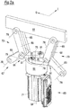
- the gear 67 again comprising two similar gear parts 73 between rotor 65 on the one hand and working unit 61 on the other hand is designed in this embodiment as a spatial coupling gear with double toggle lever arrangement.
- the rotor 65 is again arranged centrally between the two gear parts 73.
- the gear parts 73 in turn each comprise a toggle lever arrangement with two parallel straight couplings 85 and a rocker 83 articulated on the frame 47, not shown. Furthermore, each gear part 73 comprises a link 81, which on one side with the upper end of the rotor 65 and is articulated on the other side with the rocker 83, in each case via a ball joint 91.
- the two links 81 are connected to one another on the upper end of the rotor 65 by a rigid connecting piece 125. This ensures a high level of stability and ensures that, in spite of the high forces that act in particular on the articulation points of the rotor 65 for the link 81, no deformations that impair the movement sequence of the lifting mechanism occur.
- the rotor 65 is in turn set in rotation in order to lower or raise the working unit 61 depending on the direction of rotation. Shows the lowered position with bent toggle lever arrangements Fig. 2a , while Figure 2b each shows the toggle lever arrangements in an extended position in which the working unit 61 is raised to the maximum.
- the rotor 65 is fixedly attached, ie stationary with respect to the vertical direction, on the frame 47, which is represented here by two guide plates 101 spaced apart in the longitudinal direction T (cf. in particular Figure 3c ).
- the rotor 65 arranged between them is rotatably mounted on these two guide plates 101 and the two gear parts 73 in FIG Cross direction Q guided horizontally.
- guide tracks 89 are again formed in the guide plates 101.
- the gear 67 with the two gear parts 73 is in turn a planar coupling gear with a double toggle lever arrangement. All hinge axes 79 again run parallel to one another and parallel to the axis of rotation 75 of the rotor 65 and thus parallel to the longitudinal direction T.
- the rockers 83 are each articulated to the frame 47 at the lower end and articulated between the two couplings 65, which are each connected to are articulated to the working unit 61 at their upper end.
- the links of the two gear parts 73 each include two articulated link arms 82. At the articulated connection between the two core sections 82, these and thus the respective gear part 73 are positively guided in the aforementioned manner on the two guide plates 101 and thus on the frame 47.
- the part links 82 articulated on the two end faces of the rotor 65 are each designed to be curved.
- the two other part links 82 are straight and each connected to the respective rocker 83 at a point that does not coincide with the articulated connection between rocker 83 and coupling 85.
- this coupling mechanism there are consequently no common points in the sense of the common points 87 of the concept according to FIG Figures 1a-1e .
- the drive for the rotor 65 is only in Figure 3c a drive belt 77 is shown.
- the drive can be based on the concept of Figures 1a-1c be executed. It has to be taken into account here that different from the concept of Figures 1a-1c the rotor 65 is fixedly attached to the frame 47, namely is rotatably mounted between the two guide plates 101 fixed to the frame.
- a servomotor designed as a rotary drive on the one hand and the in Figure 3c
- toothed belt 77 shown can be made in any way.
- the servomotor is preferably arranged in such a way that the axis of rotation of its output shaft lies in a plane that runs perpendicular to the longitudinal direction T.
- the servomotor can be inclined as in the embodiment according to FIG Fig. 1a and 1b or assume a horizontal position as in the embodiment according to FIGS Figures 1c-1e .
- the rotor 65 is in turn arranged with the axis of rotation 75 running horizontally and parallel to the longitudinal direction T and all joint axes 79 of the planar coupling gear 67, which in turn has two gear parts 73 located in the transverse direction Q on both sides of the centrally arranged rotor 65, also run parallel to the axis of rotation 75 of the rotor 65.
- the coupling elements are each designed in two parts and a pair of parallel straight sub-couplers 86, which are articulated to the working unit 61, and a further straight sub-coupler 86, which on the one hand are connected to the first two sub-couplers 86 and on the other hand, is articulated to a pair of straight parallel rockers 83.
- the last-mentioned sub-coupler 86 is located between the respective two sub-couplers 86 or rockers 83.
- the curved links 81 are each articulated to the two rockers 83 at a different point than the sub-coupler 86, so that in this embodiment, too, no joint As with the concept of Figures 1a-1e is provided.
- a special feature of the embodiment of the Figure 4a and 4b consists in that the rotor 65 comprises two disk-shaped rotor parts 66, the axes of rotation 75 of which coincide.
- the two links 81 extend into the axial space 93 between the two rotor parts 66.
- the handlebar 81 of the in Figure 4b right transmission part 73 with the in Figure 4b front rotor disk 66 is articulated which is indicated by the circle shown on the end face of this rotor disk 66, through which the hinge axis 79 runs, while the link 81 of the in Figure 4b left gear part 73 to the in Figure 4b rear rotor disk 66 is articulated. From this joint connection is in Figure 4b only the hinge axis 79 is shown.
- the two links 81 of the two gear parts 73 are each articulated to the rotor 65 at a point radially spaced from the axis of rotation 75 - in this case to a respective rotor part 66, these two points being diametrically opposite one another , so are spaced apart from one another by 180 ° in the circumferential direction about the axis of rotation 75.
- Figure 4a again shows the working unit 61 in the most lowered position with toggle lever arrangements in the bent state, which are also implemented in this exemplary embodiment by the two gear parts 73.
- Figure 4b again shows the stretched state with the working unit 61 in the highest position.
- the two parts 66 of the rotor 65 are in principle rotatably mounted independently of one another, but nevertheless coupled to one another by a common toothed belt 77 in such a way that the two rotor parts 66 are only synchronized, but rotated in opposite directions, i.e. with opposite directions of rotation.
- the drive 63 comprises a single common toothed belt 77 which forms a loop 95, 97 at each of its two ends and rotates for this purpose is, the belt 77 in the area between the two loops 95, 97 wraps around both rotor parts over part of the circumference.
- the rotor parts 66 are provided with a toothing for the toothed belt 77 on their outer circumference.
- the drive 63 further comprises a servomotor, not shown, designed as a rotary drive, which drives a drive pinion, either directly or via a gear part, around which one of the two loops 95, 97 revolves.
- the respective other loop 97 or 95 runs around a deflection, not shown, which is preferably not driven and which is, for example, a freely rotatably mounted gear.
- the two gear parts 73 can be acted upon synchronously by means of rotors 66 rotating in opposite directions, which are rotated synchronously in opposite directions by means of a single toothed belt 77 having the aforementioned special course.
- FIGS. 5a and 5b illustrate schematically the possible configuration of the gear 67 between drive 63 and working unit 61 as a so-called Watt's planetary gear.
- a section 115 of a planetary gear is formed at one end of an elongated coupling 85 and meshes with a rotor 65, which is designed as a gear and is driven directly by means of the output shaft 69 of the servo motor 71.
- the interposition of a gear unit between motor 71 and rotor 65 is possible, but not mandatory.
- the section 115 moves on a circular path around the axis of rotation 75 of the rotor 65.
- the coupling 85 remains in a plane running perpendicular to the axis of rotation 75 of the rotor 65 and thus perpendicular to the transverse direction Q, but changes its orientation with respect to the vertical direction. This is done through an articulated connection 117 between the upper end of the coupling 85 and the working unit 61 compensated.
- Figures 6a to 6h are based for the lower working unit 61 on the concept of Figures 2a to 2c . This is consequently not dealt with in more detail, but rather the explanations relating to the Figures 2a to 2c referenced.
- the Figures 6c to 6h are only partial representations, each only showing parts of the in Figure 6a and FIG. 6b, respectively, wherein in particular of the upper working unit 64 only the support rods 121 and the carriers 123 are shown.
- the two gear parts 73 for the lower working unit 61 form a first gear section with the at Figures 2a to 2c described structure.
- a second gear section is provided with two gear parts 73a, each of which is designed analogously to the corresponding gear part 73 of the first gear section, ie a link 81a, a rocker 83a and a coupling 85a.
- the link 81a comprises two articulated part links - insofar as the link 81 according to FIG Figures 3a to 3c .
- Each partial link 81a, the rocker 83a and the coupling 85a each consist of two parallel parts.
- the gear parts 73, 73a are connected in series with respect to the rotor 65 insofar as the movement of the gear part 73a is derived from the movement of the gear part 73: the link 81a is articulated at one end with the rocker arm 83 and at the other end articulated with the rocker arm 83a and the coupling 85a connected.
- the articulated connection to its coupling 85 for the lower working unit 61 lies above the articulated connection between the frame 47 and its rocker 83, while conversely, for the upper working unit 64, the articulated connection of which to its coupling 85a is below the articulated connection between the frame 47 and its rocker 83a.
- the support rods 121 are each coupled to a carrier 123 which is hingedly connected to the free end of the coupling 85a and is thus moved in the vertical direction by means of the coupling 85a.
- Analogous to the stabilization on the rotor 65 by the connecting piece 125 - as above in connection with Figure 2c explained - are the coupling 85a of the two gear parts 73a by a rigid connecting piece 125a (cf. in particular Figures 6e and 6f ) connected with each other.
- the coupling 85a can be rotated relative to the carrier 123 and relative to the connecting piece 125a about the same horizontal joint axis 79.
- the two working units 61, 64 are moved towards one another into a closed position ( Figure 6a , 6c , 6e , 6g ) or in an open position ( Figure 6b , 6d , 6f , 6h ) emotional.
- the lower working unit 61 is guided on the frame 47 via rollers 113 attached to a strut 62, with FIG Figures 6c and 6d only the strut 62, but not the lower working unit 61, is shown, so that in particular in FIG Fig. 6d an otherwise largely covered wall 127 is visible.
- the lower working unit 61 is provided with a lower working tool 61a - here a punching tool - and the upper working unit 64 with an upper working tool 64a - here a counter-punching tool for the lower punching tool 61a.
- the two tools 61a, 64a act when the closed one is reached Position together in order, for example, to separate packages not shown here, as explained in the introductory part as an application example for the invention.
Landscapes
- Engineering & Computer Science (AREA)
- Mechanical Engineering (AREA)
- Life Sciences & Earth Sciences (AREA)
- Forests & Forestry (AREA)
- Auxiliary Devices For And Details Of Packaging Control (AREA)
Priority Applications (1)
| Application Number | Priority Date | Filing Date | Title |
|---|---|---|---|
| PL20155990T PL3715267T3 (pl) | 2019-03-26 | 2020-02-07 | Stanowisko robocze do maszyny pakującej |
Applications Claiming Priority (2)
| Application Number | Priority Date | Filing Date | Title |
|---|---|---|---|
| DE102019107784 | 2019-03-26 | ||
| DE102019114126.5A DE102019114126A1 (de) | 2019-03-26 | 2019-05-27 | Arbeitsstation für eine Verpackungsmaschine |
Publications (2)
| Publication Number | Publication Date |
|---|---|
| EP3715267A1 true EP3715267A1 (fr) | 2020-09-30 |
| EP3715267B1 EP3715267B1 (fr) | 2021-08-18 |
Family
ID=69526131
Family Applications (1)
| Application Number | Title | Priority Date | Filing Date |
|---|---|---|---|
| EP20155990.3A Revoked EP3715267B1 (fr) | 2019-03-26 | 2020-02-07 | Station de travail pour une machine d'emballage |
Country Status (3)
| Country | Link |
|---|---|
| EP (1) | EP3715267B1 (fr) |
| ES (1) | ES2891900T3 (fr) |
| PL (1) | PL3715267T3 (fr) |
Cited By (7)
| Publication number | Priority date | Publication date | Assignee | Title |
|---|---|---|---|---|
| EP4000824A1 (fr) * | 2020-11-18 | 2022-05-25 | Weber Maschinenbau GmbH Breidenbach | Dispositif de découpe des emballages alimentaires dans une direction longitudinale et procédé de fonctionnement d'un tel dispositif |
| DE102020133472A1 (de) | 2020-12-14 | 2022-06-15 | Haver & Boecker Ohg | Verlagerungsvorrichtung und Verfahren zum Verlagern |
| EP4049937A1 (fr) * | 2021-02-24 | 2022-08-31 | MULTIVAC Sepp Haggenmüller SE & Co. KG | Station d'étanchéité avec système de levage |
| US20240228093A1 (en) * | 2021-05-03 | 2024-07-11 | G.D S.P.A. | Packaging apparatus and process for articles to be packaged |
| US12157588B2 (en) | 2020-05-13 | 2024-12-03 | Haver & Boecker Ohg | Displacement device and method for displacement |
| US12252287B2 (en) | 2020-05-13 | 2025-03-18 | Haver & Boecker Ohg | Cleaning apparatus and method for cleaning |
| US12420970B2 (en) | 2020-05-13 | 2025-09-23 | Haver & Boecker Ohg | Displacement device and method for displacement |
Families Citing this family (1)
| Publication number | Priority date | Publication date | Assignee | Title |
|---|---|---|---|---|
| DE102023136884A1 (de) * | 2023-12-29 | 2025-07-03 | Bausch + Ströbel SE + Co. KG | Handhabungsvorrichtung für pharmazeutisches Produktionsmaterial, Handhabungssystem mit einer Handhabungsvorrichtung und Anlage zum Verarbeiten pharmazeutischer Behälter |
Citations (9)
| Publication number | Priority date | Publication date | Assignee | Title |
|---|---|---|---|---|
| WO2004110871A1 (fr) * | 2003-06-13 | 2004-12-23 | Cfs Germany Gmbh | Station de travail et machine d'emballage |
| DE10351567A1 (de) | 2003-11-03 | 2005-06-02 | Cfs Germany Gmbh | Verpackungsmaschine mit einem Elektrolinearzylinder |
| WO2005075291A2 (fr) * | 2004-02-06 | 2005-08-18 | Cfs Germany Gmbh | Machine d'emballage comportant plusieurs dispositifs de levage par poste de travail |
| DE102006050415A1 (de) * | 2006-10-20 | 2008-04-24 | Cfs Germany Gmbh | Verpackungsmaschine mit einem regelbaren Pneumatik/Hydraulik-Antrieb |
| EP2384866A1 (fr) * | 2010-05-06 | 2011-11-09 | MULTIVAC Sepp Haggenmüller GmbH & Co KG | Dispositif de découpe pour une machine d'emballage |
| EP2522580A1 (fr) * | 2011-05-10 | 2012-11-14 | MULTIVAC Sepp Haggenmüller GmbH & Co KG | Dispositif de changement d'outil |
| EP2666727A1 (fr) * | 2012-05-24 | 2013-11-27 | MULTIVAC Sepp Haggenmüller GmbH & Co KG | Dispositif de levage pour une machine d'emballage |
| EP2896573A1 (fr) * | 2014-01-21 | 2015-07-22 | Multivac Sepp Haggenmüller GmbH & Co. KG | Thermoformeuse avec station de formage du film supérieur et méthode correspondante |
| DE202015009453U1 (de) * | 2015-08-11 | 2017-08-31 | Multivac Sepp Haggenmüller Se & Co. Kg | Zugkurbelhubwerk für Verpackungsmaschine |
Family Cites Families (4)
| Publication number | Priority date | Publication date | Assignee | Title |
|---|---|---|---|---|
| DE19734513A1 (de) | 1997-08-08 | 1999-02-11 | Multivac Haggenmueller Kg | Hubeinrichtung für eine Arbeitsstation einer Verpackungsmaschine |
| DE102011011560A1 (de) | 2011-02-18 | 2012-08-23 | Jörg von Seggern Maschinenbau GmbH | Hubvorrichtung für ein Werkzeug |
| EP2769829B1 (fr) | 2013-02-20 | 2016-06-08 | MULTIVAC Sepp Haggenmüller SE & Co. KG | Machine d'emballage par emboutissage avec dispositif de levage, et un procédé |
| DE102013010416A1 (de) | 2013-06-21 | 2014-12-24 | Jörg von Seggern Maschinenbau GmbH | Hubvorrichtung für ein Werkzeug |
-
2020
- 2020-02-07 ES ES20155990T patent/ES2891900T3/es active Active
- 2020-02-07 EP EP20155990.3A patent/EP3715267B1/fr not_active Revoked
- 2020-02-07 PL PL20155990T patent/PL3715267T3/pl unknown
Patent Citations (9)
| Publication number | Priority date | Publication date | Assignee | Title |
|---|---|---|---|---|
| WO2004110871A1 (fr) * | 2003-06-13 | 2004-12-23 | Cfs Germany Gmbh | Station de travail et machine d'emballage |
| DE10351567A1 (de) | 2003-11-03 | 2005-06-02 | Cfs Germany Gmbh | Verpackungsmaschine mit einem Elektrolinearzylinder |
| WO2005075291A2 (fr) * | 2004-02-06 | 2005-08-18 | Cfs Germany Gmbh | Machine d'emballage comportant plusieurs dispositifs de levage par poste de travail |
| DE102006050415A1 (de) * | 2006-10-20 | 2008-04-24 | Cfs Germany Gmbh | Verpackungsmaschine mit einem regelbaren Pneumatik/Hydraulik-Antrieb |
| EP2384866A1 (fr) * | 2010-05-06 | 2011-11-09 | MULTIVAC Sepp Haggenmüller GmbH & Co KG | Dispositif de découpe pour une machine d'emballage |
| EP2522580A1 (fr) * | 2011-05-10 | 2012-11-14 | MULTIVAC Sepp Haggenmüller GmbH & Co KG | Dispositif de changement d'outil |
| EP2666727A1 (fr) * | 2012-05-24 | 2013-11-27 | MULTIVAC Sepp Haggenmüller GmbH & Co KG | Dispositif de levage pour une machine d'emballage |
| EP2896573A1 (fr) * | 2014-01-21 | 2015-07-22 | Multivac Sepp Haggenmüller GmbH & Co. KG | Thermoformeuse avec station de formage du film supérieur et méthode correspondante |
| DE202015009453U1 (de) * | 2015-08-11 | 2017-08-31 | Multivac Sepp Haggenmüller Se & Co. Kg | Zugkurbelhubwerk für Verpackungsmaschine |
Cited By (7)
| Publication number | Priority date | Publication date | Assignee | Title |
|---|---|---|---|---|
| US12157588B2 (en) | 2020-05-13 | 2024-12-03 | Haver & Boecker Ohg | Displacement device and method for displacement |
| US12252287B2 (en) | 2020-05-13 | 2025-03-18 | Haver & Boecker Ohg | Cleaning apparatus and method for cleaning |
| US12420970B2 (en) | 2020-05-13 | 2025-09-23 | Haver & Boecker Ohg | Displacement device and method for displacement |
| EP4000824A1 (fr) * | 2020-11-18 | 2022-05-25 | Weber Maschinenbau GmbH Breidenbach | Dispositif de découpe des emballages alimentaires dans une direction longitudinale et procédé de fonctionnement d'un tel dispositif |
| DE102020133472A1 (de) | 2020-12-14 | 2022-06-15 | Haver & Boecker Ohg | Verlagerungsvorrichtung und Verfahren zum Verlagern |
| EP4049937A1 (fr) * | 2021-02-24 | 2022-08-31 | MULTIVAC Sepp Haggenmüller SE & Co. KG | Station d'étanchéité avec système de levage |
| US20240228093A1 (en) * | 2021-05-03 | 2024-07-11 | G.D S.P.A. | Packaging apparatus and process for articles to be packaged |
Also Published As
| Publication number | Publication date |
|---|---|
| PL3715267T3 (pl) | 2022-01-10 |
| EP3715267B1 (fr) | 2021-08-18 |
| ES2891900T3 (es) | 2022-01-31 |
Similar Documents
| Publication | Publication Date | Title |
|---|---|---|
| EP3715267B1 (fr) | Station de travail pour une machine d'emballage | |
| DE102010019634B3 (de) | Schneideinrichtung für eine Verpackungsmaschine | |
| EP2706013B1 (fr) | Machine de fermeture de coques | |
| EP3712079B1 (fr) | Poste de travail pourvu de mécanisme de levage pour une machine d'emballage | |
| DE102014102333A1 (de) | Vorrichtung und Verfahren zur Vorfaltung von Packungsmänteln | |
| EP2412637B1 (fr) | Machine d'emballage dotée de plusieurs stations de travail | |
| EP4228973A1 (fr) | Machine d'emballage et procédé pour l'emballage d'un groupe de récipients composé de plusieurs récipients | |
| WO2004110871A1 (fr) | Station de travail et machine d'emballage | |
| EP1389166A2 (fr) | Dispositif pour inserer un produit a emballer dans un materiau d'emballage | |
| DE10351567A1 (de) | Verpackungsmaschine mit einem Elektrolinearzylinder | |
| EP4000824B1 (fr) | Dispositif de découpe des emballages alimentaires dans une direction longitudinale et procédé de fonctionnement d'un tel dispositif | |
| DE102019114126A1 (de) | Arbeitsstation für eine Verpackungsmaschine | |
| DE1502853B2 (de) | Vorrichtung zum intermittierenden zufuehren von streifenfoermigem material zu einer schneideinrichtung | |
| EP2769829B1 (fr) | Machine d'emballage par emboutissage avec dispositif de levage, et un procédé | |
| WO2005075291A2 (fr) | Machine d'emballage comportant plusieurs dispositifs de levage par poste de travail | |
| DE2917387C3 (de) | Tiefziehmaschine zum Herstellen von Behältern aus thermoplastischer Folie | |
| DE102007003930B4 (de) | Schlauchbeutelmaschine | |
| EP1782930A1 (fr) | Méthode et dispositif pour rogner des signatures | |
| DE102021109656A1 (de) | Trennstation für eine verpackungsmaschine | |
| DE102024106754B4 (de) | Längstrennschweißeinrichtung mit Austreibvorrichtung | |
| DE1502853C3 (de) | Vorrichtung zum intermittierenden Zuführen von streifenförmigem Material zu einer schneideinrichtung | |
| WO2024175724A1 (fr) | Dispositif de transport de produit à rouleau de traction | |
| DE8201399U1 (de) | Dreimesserschneidemaschine |
Legal Events
| Date | Code | Title | Description |
|---|---|---|---|
| PUAI | Public reference made under article 153(3) epc to a published international application that has entered the european phase |
Free format text: ORIGINAL CODE: 0009012 |
|
| STAA | Information on the status of an ep patent application or granted ep patent |
Free format text: STATUS: THE APPLICATION HAS BEEN PUBLISHED |
|
| AK | Designated contracting states |
Kind code of ref document: A1 Designated state(s): AL AT BE BG CH CY CZ DE DK EE ES FI FR GB GR HR HU IE IS IT LI LT LU LV MC MK MT NL NO PL PT RO RS SE SI SK SM TR |
|
| AX | Request for extension of the european patent |
Extension state: BA ME |
|
| STAA | Information on the status of an ep patent application or granted ep patent |
Free format text: STATUS: REQUEST FOR EXAMINATION WAS MADE |
|
| 17P | Request for examination filed |
Effective date: 20201014 |
|
| RBV | Designated contracting states (corrected) |
Designated state(s): AL AT BE BG CH CY CZ DE DK EE ES FI FR GB GR HR HU IE IS IT LI LT LU LV MC MK MT NL NO PL PT RO RS SE SI SK SM TR |
|
| GRAP | Despatch of communication of intention to grant a patent |
Free format text: ORIGINAL CODE: EPIDOSNIGR1 |
|
| STAA | Information on the status of an ep patent application or granted ep patent |
Free format text: STATUS: GRANT OF PATENT IS INTENDED |
|
| INTG | Intention to grant announced |
Effective date: 20210323 |
|
| GRAS | Grant fee paid |
Free format text: ORIGINAL CODE: EPIDOSNIGR3 |
|
| GRAA | (expected) grant |
Free format text: ORIGINAL CODE: 0009210 |
|
| STAA | Information on the status of an ep patent application or granted ep patent |
Free format text: STATUS: THE PATENT HAS BEEN GRANTED |
|
| AK | Designated contracting states |
Kind code of ref document: B1 Designated state(s): AL AT BE BG CH CY CZ DE DK EE ES FI FR GB GR HR HU IE IS IT LI LT LU LV MC MK MT NL NO PL PT RO RS SE SI SK SM TR |
|
| REG | Reference to a national code |
Ref country code: GB Ref legal event code: FG4D Free format text: NOT ENGLISH |
|
| REG | Reference to a national code |
Ref country code: CH Ref legal event code: EP |
|
| REG | Reference to a national code |
Ref country code: DE Ref legal event code: R096 Ref document number: 502020000131 Country of ref document: DE |
|
| REG | Reference to a national code |
Ref country code: IE Ref legal event code: FG4D Free format text: LANGUAGE OF EP DOCUMENT: GERMAN Ref country code: AT Ref legal event code: REF Ref document number: 1421438 Country of ref document: AT Kind code of ref document: T Effective date: 20210915 |
|
| REG | Reference to a national code |
Ref country code: NL Ref legal event code: FP |
|
| REG | Reference to a national code |
Ref country code: LT Ref legal event code: MG9D |
|
| PG25 | Lapsed in a contracting state [announced via postgrant information from national office to epo] |
Ref country code: LT Free format text: LAPSE BECAUSE OF FAILURE TO SUBMIT A TRANSLATION OF THE DESCRIPTION OR TO PAY THE FEE WITHIN THE PRESCRIBED TIME-LIMIT Effective date: 20210818 Ref country code: BG Free format text: LAPSE BECAUSE OF FAILURE TO SUBMIT A TRANSLATION OF THE DESCRIPTION OR TO PAY THE FEE WITHIN THE PRESCRIBED TIME-LIMIT Effective date: 20211118 Ref country code: HR Free format text: LAPSE BECAUSE OF FAILURE TO SUBMIT A TRANSLATION OF THE DESCRIPTION OR TO PAY THE FEE WITHIN THE PRESCRIBED TIME-LIMIT Effective date: 20210818 Ref country code: FI Free format text: LAPSE BECAUSE OF FAILURE TO SUBMIT A TRANSLATION OF THE DESCRIPTION OR TO PAY THE FEE WITHIN THE PRESCRIBED TIME-LIMIT Effective date: 20210818 Ref country code: NO Free format text: LAPSE BECAUSE OF FAILURE TO SUBMIT A TRANSLATION OF THE DESCRIPTION OR TO PAY THE FEE WITHIN THE PRESCRIBED TIME-LIMIT Effective date: 20211118 Ref country code: PT Free format text: LAPSE BECAUSE OF FAILURE TO SUBMIT A TRANSLATION OF THE DESCRIPTION OR TO PAY THE FEE WITHIN THE PRESCRIBED TIME-LIMIT Effective date: 20211220 Ref country code: RS Free format text: LAPSE BECAUSE OF FAILURE TO SUBMIT A TRANSLATION OF THE DESCRIPTION OR TO PAY THE FEE WITHIN THE PRESCRIBED TIME-LIMIT Effective date: 20210818 Ref country code: SE Free format text: LAPSE BECAUSE OF FAILURE TO SUBMIT A TRANSLATION OF THE DESCRIPTION OR TO PAY THE FEE WITHIN THE PRESCRIBED TIME-LIMIT Effective date: 20210818 |
|
| REG | Reference to a national code |
Ref country code: ES Ref legal event code: FG2A Ref document number: 2891900 Country of ref document: ES Kind code of ref document: T3 Effective date: 20220131 |
|
| PG25 | Lapsed in a contracting state [announced via postgrant information from national office to epo] |
Ref country code: LV Free format text: LAPSE BECAUSE OF FAILURE TO SUBMIT A TRANSLATION OF THE DESCRIPTION OR TO PAY THE FEE WITHIN THE PRESCRIBED TIME-LIMIT Effective date: 20210818 Ref country code: GR Free format text: LAPSE BECAUSE OF FAILURE TO SUBMIT A TRANSLATION OF THE DESCRIPTION OR TO PAY THE FEE WITHIN THE PRESCRIBED TIME-LIMIT Effective date: 20211119 |
|
| REG | Reference to a national code |
Ref country code: DE Ref legal event code: R026 Ref document number: 502020000131 Country of ref document: DE |
|
| PG25 | Lapsed in a contracting state [announced via postgrant information from national office to epo] |
Ref country code: DK Free format text: LAPSE BECAUSE OF FAILURE TO SUBMIT A TRANSLATION OF THE DESCRIPTION OR TO PAY THE FEE WITHIN THE PRESCRIBED TIME-LIMIT Effective date: 20210818 |
|
| PLBI | Opposition filed |
Free format text: ORIGINAL CODE: 0009260 |
|
| PLAB | Opposition data, opponent's data or that of the opponent's representative modified |
Free format text: ORIGINAL CODE: 0009299OPPO |
|
| 26 | Opposition filed |
Opponent name: MULTIVAC SEPP HAGGENMUELLER SE & CO. KG Effective date: 20220427 |
|
| PG25 | Lapsed in a contracting state [announced via postgrant information from national office to epo] |
Ref country code: SM Free format text: LAPSE BECAUSE OF FAILURE TO SUBMIT A TRANSLATION OF THE DESCRIPTION OR TO PAY THE FEE WITHIN THE PRESCRIBED TIME-LIMIT Effective date: 20210818 Ref country code: SK Free format text: LAPSE BECAUSE OF FAILURE TO SUBMIT A TRANSLATION OF THE DESCRIPTION OR TO PAY THE FEE WITHIN THE PRESCRIBED TIME-LIMIT Effective date: 20210818 Ref country code: RO Free format text: LAPSE BECAUSE OF FAILURE TO SUBMIT A TRANSLATION OF THE DESCRIPTION OR TO PAY THE FEE WITHIN THE PRESCRIBED TIME-LIMIT Effective date: 20210818 Ref country code: EE Free format text: LAPSE BECAUSE OF FAILURE TO SUBMIT A TRANSLATION OF THE DESCRIPTION OR TO PAY THE FEE WITHIN THE PRESCRIBED TIME-LIMIT Effective date: 20210818 Ref country code: CZ Free format text: LAPSE BECAUSE OF FAILURE TO SUBMIT A TRANSLATION OF THE DESCRIPTION OR TO PAY THE FEE WITHIN THE PRESCRIBED TIME-LIMIT Effective date: 20210818 Ref country code: AL Free format text: LAPSE BECAUSE OF FAILURE TO SUBMIT A TRANSLATION OF THE DESCRIPTION OR TO PAY THE FEE WITHIN THE PRESCRIBED TIME-LIMIT Effective date: 20210818 |
|
| PLAX | Notice of opposition and request to file observation + time limit sent |
Free format text: ORIGINAL CODE: EPIDOSNOBS2 |
|
| R26 | Opposition filed (corrected) |
Opponent name: MULTIVAC SEPP HAGGENMUELLER SE & CO. KG Effective date: 20220427 |
|
| PG25 | Lapsed in a contracting state [announced via postgrant information from national office to epo] |
Ref country code: SI Free format text: LAPSE BECAUSE OF FAILURE TO SUBMIT A TRANSLATION OF THE DESCRIPTION OR TO PAY THE FEE WITHIN THE PRESCRIBED TIME-LIMIT Effective date: 20210818 |
|
| PG25 | Lapsed in a contracting state [announced via postgrant information from national office to epo] |
Ref country code: MC Free format text: LAPSE BECAUSE OF FAILURE TO SUBMIT A TRANSLATION OF THE DESCRIPTION OR TO PAY THE FEE WITHIN THE PRESCRIBED TIME-LIMIT Effective date: 20210818 |
|
| PLBB | Reply of patent proprietor to notice(s) of opposition received |
Free format text: ORIGINAL CODE: EPIDOSNOBS3 |
|
| REG | Reference to a national code |
Ref country code: BE Ref legal event code: MM Effective date: 20220228 |
|
| PG25 | Lapsed in a contracting state [announced via postgrant information from national office to epo] |
Ref country code: LU Free format text: LAPSE BECAUSE OF NON-PAYMENT OF DUE FEES Effective date: 20220207 |
|
| PG25 | Lapsed in a contracting state [announced via postgrant information from national office to epo] |
Ref country code: IE Free format text: LAPSE BECAUSE OF NON-PAYMENT OF DUE FEES Effective date: 20220207 |
|
| PG25 | Lapsed in a contracting state [announced via postgrant information from national office to epo] |
Ref country code: BE Free format text: LAPSE BECAUSE OF NON-PAYMENT OF DUE FEES Effective date: 20220228 |
|
| P01 | Opt-out of the competence of the unified patent court (upc) registered |
Effective date: 20230522 |
|
| PLAB | Opposition data, opponent's data or that of the opponent's representative modified |
Free format text: ORIGINAL CODE: 0009299OPPO |
|
| R26 | Opposition filed (corrected) |
Opponent name: MULTIVAC SEPP HAGGENMUELLER SE & CO. KG Effective date: 20220427 |
|
| REG | Reference to a national code |
Ref country code: CH Ref legal event code: PL |
|
| PG25 | Lapsed in a contracting state [announced via postgrant information from national office to epo] |
Ref country code: LI Free format text: LAPSE BECAUSE OF NON-PAYMENT OF DUE FEES Effective date: 20230228 Ref country code: CH Free format text: LAPSE BECAUSE OF NON-PAYMENT OF DUE FEES Effective date: 20230228 |
|
| REG | Reference to a national code |
Ref country code: NL Ref legal event code: HC Owner name: WEBER FOOD TECHNOLOGY GMBH; DE Free format text: DETAILS ASSIGNMENT: CHANGE OF OWNER(S), CHANGE OF OWNER(S) NAME; FORMER OWNER NAME: WEBER MASCHINENBAU GMBH BREIDENBACH Effective date: 20240206 |
|
| RAP4 | Party data changed (patent owner data changed or rights of a patent transferred) |
Owner name: WEBER FOOD TECHNOLOGY GMBH |
|
| PGFP | Annual fee paid to national office [announced via postgrant information from national office to epo] |
Ref country code: ES Payment date: 20240319 Year of fee payment: 5 Ref country code: NL Payment date: 20240220 Year of fee payment: 5 |
|
| REG | Reference to a national code |
Ref country code: DE Ref legal event code: R081 Ref document number: 502020000131 Country of ref document: DE Owner name: WEBER FOOD TECHNOLOGY GMBH, DE Free format text: FORMER OWNER: WEBER MASCHINENBAU GMBH BREIDENBACH, 35236 BREIDENBACH, DE |
|
| PG25 | Lapsed in a contracting state [announced via postgrant information from national office to epo] |
Ref country code: MK Free format text: LAPSE BECAUSE OF FAILURE TO SUBMIT A TRANSLATION OF THE DESCRIPTION OR TO PAY THE FEE WITHIN THE PRESCRIBED TIME-LIMIT Effective date: 20210818 Ref country code: CY Free format text: LAPSE BECAUSE OF FAILURE TO SUBMIT A TRANSLATION OF THE DESCRIPTION OR TO PAY THE FEE WITHIN THE PRESCRIBED TIME-LIMIT Effective date: 20210818 |
|
| PGFP | Annual fee paid to national office [announced via postgrant information from national office to epo] |
Ref country code: DE Payment date: 20240216 Year of fee payment: 5 Ref country code: GB Payment date: 20240222 Year of fee payment: 5 |
|
| PG25 | Lapsed in a contracting state [announced via postgrant information from national office to epo] |
Ref country code: HU Free format text: LAPSE BECAUSE OF FAILURE TO SUBMIT A TRANSLATION OF THE DESCRIPTION OR TO PAY THE FEE WITHIN THE PRESCRIBED TIME-LIMIT; INVALID AB INITIO Effective date: 20200207 |
|
| PGFP | Annual fee paid to national office [announced via postgrant information from national office to epo] |
Ref country code: PL Payment date: 20240126 Year of fee payment: 5 Ref country code: IT Payment date: 20240229 Year of fee payment: 5 Ref country code: FR Payment date: 20240222 Year of fee payment: 5 |
|
| PG25 | Lapsed in a contracting state [announced via postgrant information from national office to epo] |
Ref country code: TR Free format text: LAPSE BECAUSE OF FAILURE TO SUBMIT A TRANSLATION OF THE DESCRIPTION OR TO PAY THE FEE WITHIN THE PRESCRIBED TIME-LIMIT Effective date: 20210818 |
|
| PG25 | Lapsed in a contracting state [announced via postgrant information from national office to epo] |
Ref country code: MT Free format text: LAPSE BECAUSE OF FAILURE TO SUBMIT A TRANSLATION OF THE DESCRIPTION OR TO PAY THE FEE WITHIN THE PRESCRIBED TIME-LIMIT Effective date: 20210818 |
|
| PGFP | Annual fee paid to national office [announced via postgrant information from national office to epo] |
Ref country code: AT Payment date: 20250417 Year of fee payment: 5 |
|
| REG | Reference to a national code |
Ref country code: DE Ref legal event code: R064 Ref document number: 502020000131 Country of ref document: DE Ref country code: DE Ref legal event code: R103 Ref document number: 502020000131 Country of ref document: DE |
|
| RDAF | Communication despatched that patent is revoked |
Free format text: ORIGINAL CODE: EPIDOSNREV1 |
|
| REG | Reference to a national code |
Ref country code: DE Ref legal event code: R119 Ref document number: 502020000131 Country of ref document: DE |
|
| RDAG | Patent revoked |
Free format text: ORIGINAL CODE: 0009271 |
|
| STAA | Information on the status of an ep patent application or granted ep patent |
Free format text: STATUS: PATENT REVOKED |
|
| REG | Reference to a national code |
Ref country code: NL Ref legal event code: MM Effective date: 20250301 Ref country code: CH Ref legal event code: N12 Free format text: ST27 STATUS EVENT CODE: U-0-0-N10-N12 (AS PROVIDED BY THE NATIONAL OFFICE) Effective date: 20251008 |
|
| GBPC | Gb: european patent ceased through non-payment of renewal fee |
Effective date: 20250207 |
|
| 27W | Patent revoked |
Effective date: 20250630 |
|
| PG25 | Lapsed in a contracting state [announced via postgrant information from national office to epo] |
Ref country code: NL Free format text: LAPSE BECAUSE OF NON-PAYMENT OF DUE FEES Effective date: 20250301 |
|
| PG25 | Lapsed in a contracting state [announced via postgrant information from national office to epo] |
Ref country code: GB Free format text: LAPSE BECAUSE OF NON-PAYMENT OF DUE FEES Effective date: 20250207 |
|
| PG25 | Lapsed in a contracting state [announced via postgrant information from national office to epo] |
Ref country code: FR Free format text: LAPSE BECAUSE OF NON-PAYMENT OF DUE FEES Effective date: 20250228 |
|
| REG | Reference to a national code |
Ref country code: AT Ref legal event code: MA03 Ref document number: 1421438 Country of ref document: AT Kind code of ref document: T Effective date: 20250630 |
|
| PG25 | Lapsed in a contracting state [announced via postgrant information from national office to epo] |
Ref country code: PL Free format text: LAPSE BECAUSE OF NON-PAYMENT OF DUE FEES Effective date: 20250207 |