EP3715295A1 - Hülse zum verfolgen einer spule, wickelvorrichtung mit spulenverfolgungsvorrichtung und wickelverfahren dergleichen - Google Patents
Hülse zum verfolgen einer spule, wickelvorrichtung mit spulenverfolgungsvorrichtung und wickelverfahren dergleichen Download PDFInfo
- Publication number
- EP3715295A1 EP3715295A1 EP20163492.0A EP20163492A EP3715295A1 EP 3715295 A1 EP3715295 A1 EP 3715295A1 EP 20163492 A EP20163492 A EP 20163492A EP 3715295 A1 EP3715295 A1 EP 3715295A1
- Authority
- EP
- European Patent Office
- Prior art keywords
- tube
- reel
- identification device
- winding
- winding apparatus
- Prior art date
- Legal status (The legal status is an assumption and is not a legal conclusion. Google has not performed a legal analysis and makes no representation as to the accuracy of the status listed.)
- Granted
Links
Images






Classifications
-
- B—PERFORMING OPERATIONS; TRANSPORTING
- B65—CONVEYING; PACKING; STORING; HANDLING THIN OR FILAMENTARY MATERIAL
- B65H—HANDLING THIN OR FILAMENTARY MATERIAL, e.g. SHEETS, WEBS, CABLES
- B65H75/00—Storing webs, tapes, or filamentary material, e.g. on reels
- B65H75/02—Cores, formers, supports, or holders for coiled, wound, or folded material, e.g. reels, spindles, bobbins, cop tubes, cans, mandrels or chucks
- B65H75/04—Kinds or types
- B65H75/08—Kinds or types of circular or polygonal cross-section
- B65H75/10—Kinds or types of circular or polygonal cross-section without flanges, e.g. cop tubes
-
- B—PERFORMING OPERATIONS; TRANSPORTING
- B65—CONVEYING; PACKING; STORING; HANDLING THIN OR FILAMENTARY MATERIAL
- B65H—HANDLING THIN OR FILAMENTARY MATERIAL, e.g. SHEETS, WEBS, CABLES
- B65H63/00—Warning or safety devices, e.g. automatic fault detectors, stop-motions ; Quality control of the package
- B65H63/003—Warning or safety devices, e.g. automatic fault detectors, stop-motions ; Quality control of the package responsive to winding of yarns around rotating cylinders
-
- B—PERFORMING OPERATIONS; TRANSPORTING
- B65—CONVEYING; PACKING; STORING; HANDLING THIN OR FILAMENTARY MATERIAL
- B65H—HANDLING THIN OR FILAMENTARY MATERIAL, e.g. SHEETS, WEBS, CABLES
- B65H67/00—Replacing or removing cores, receptacles, or completed packages at paying-out, winding, or depositing stations
- B65H67/04—Arrangements for removing completed take-up packages and or replacing by cores, formers, or empty receptacles at winding or depositing stations; Transferring material between adjacent full and empty take-up elements
- B65H67/0405—Arrangements for removing completed take-up packages or for loading an empty core
- B65H67/0417—Arrangements for removing completed take-up packages or for loading an empty core for loading an empty core
-
- B—PERFORMING OPERATIONS; TRANSPORTING
- B65—CONVEYING; PACKING; STORING; HANDLING THIN OR FILAMENTARY MATERIAL
- B65H—HANDLING THIN OR FILAMENTARY MATERIAL, e.g. SHEETS, WEBS, CABLES
- B65H67/00—Replacing or removing cores, receptacles, or completed packages at paying-out, winding, or depositing stations
- B65H67/06—Supplying cores, receptacles, or packages to, or transporting from, winding or depositing stations
- B65H67/063—Marking or identifying devices for packages
-
- B—PERFORMING OPERATIONS; TRANSPORTING
- B65—CONVEYING; PACKING; STORING; HANDLING THIN OR FILAMENTARY MATERIAL
- B65H—HANDLING THIN OR FILAMENTARY MATERIAL, e.g. SHEETS, WEBS, CABLES
- B65H75/00—Storing webs, tapes, or filamentary material, e.g. on reels
- B65H75/02—Cores, formers, supports, or holders for coiled, wound, or folded material, e.g. reels, spindles, bobbins, cop tubes, cans, mandrels or chucks
- B65H75/18—Constructional details
- B65H75/182—Identification means
-
- B—PERFORMING OPERATIONS; TRANSPORTING
- B65—CONVEYING; PACKING; STORING; HANDLING THIN OR FILAMENTARY MATERIAL
- B65H—HANDLING THIN OR FILAMENTARY MATERIAL, e.g. SHEETS, WEBS, CABLES
- B65H2557/00—Means for control not provided for in groups B65H2551/00 - B65H2555/00
- B65H2557/50—Use of particular electromagnetic waves, e.g. light, radiowaves or microwaves
-
- B—PERFORMING OPERATIONS; TRANSPORTING
- B65—CONVEYING; PACKING; STORING; HANDLING THIN OR FILAMENTARY MATERIAL
- B65H—HANDLING THIN OR FILAMENTARY MATERIAL, e.g. SHEETS, WEBS, CABLES
- B65H2701/00—Handled material; Storage means
- B65H2701/30—Handled filamentary material
- B65H2701/31—Textiles threads or artificial strands of filaments
Definitions
- the present invention relates to a tube for tracking a reel, a winding apparatus with a reel tracking device and a winding method comprising the tracking of a reel.
- the thread or yarn produced is wound about a tube to form a reel in winding systems.
- thread or monofilament or continuous filament means a single filament or continuous bave (e.g. in the case of silk, artificial or man-made fibers), while the term “yarn” means the set of fibrils of variable length which are parallelized and joined by twisting.
- the reel is made by winding the thread of a spool after it was unwound from the spool and any defects were removed. In any case, the thread is wound about a tube which may have various shapes and materials. Cylindrical or conical tubes made of plastic or cardboard are typically used.
- Winding machines have a number of winding units, each of which forms a reel by appropriately accumulating the yarn on a tube.
- the tubes are positioned in baskets above the winding head.
- the doffing cart used by the reeling machine takes a tube from the basket and positions it on the winding head.
- the reel consisting of the tube plus the deposited yarn, i.e. wound, on it, is removed from the winding unit by the doffing cart.
- the doffing cart is positioned on the winding unit and removes the newly formed reel by loading a new tube on which the winding unit will form a new reel.
- the known solutions do not provide any tracking of the reels formed by each spinning unit; in other words, the reels, once formed, are stacked in baskets as a function of the production batch.
- reference numeral 4 indicates a winding apparatus, as described in greater detail below.
- the present invention preferably but not exclusively applies to a winding apparatus in which the thread unwound from a spool is wound on a reel after any defects have been removed in a winding unit.
- the present invention can be applied to a generic spinning apparatus, in which the thread is made, e.g. with air-jet or open-end technique, and then wound on a tube, in order to keep track of all the processes undergone by the thread itself (as described in greater detail below).
- the winding apparatus 4 may be of any type, shape, and size.
- Said winding apparatus 4 typically comprises a spool on which the thread containing defects is wound, means for unwinding the thread from the spool, a yarn cleaner which analyses the unwound thread and detects its defects.
- the winding apparatus 4 further comprises means for cutting the portion of defective thread and means for reattaching the clues formed with the above-mentioned cutting of the portion of the defective thread.
- the winding apparatus 4 comprises means for rewinding the thread, having removed any defects, on a tube 8 so as to form a reel 12.
- the reel 12 is biased in rotation by a thread guide shaped, for example, to impart a traversing movement of the thread being wound on the reel 12 and/or a rotation movement of the reel 12 to wind the thread about the tube 8.
- the reel 12 is formed by winding the thread about the tube 8.
- the tube 8 is advantageously configured to allow the tracking of the reel 12 wound on it.
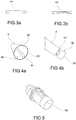
- the tube 8 comprises a tube body 20 with an outer lateral surface 24 adapted to receive a winding yarn so as to form a reel 12.
- the tube body 20 is axially symmetrical with respect to an axis of symmetry S-S.
- the tube body is cylindrical or conical or better truncated conical with respect to said axis of symmetry S-S.
- the tube body 20 is usually made of cardboard or plastic.
- the tube body 20 extends between opposite axial ends 28,32, each provided with a lateral seat 36 for at least partially housing a respective tailstock for the rotational support of the tube 8 during yarn winding.
- said tube body 20 is associated with an identification device 44 (EPC: electronic product code) adapted to uniquely identifying said tube 8.
- EPC electronic product code
- said identification device 44 is a radio frequency identification device (RFID) comprising an electronic identification code (EPC).
- RFID radio frequency identification device
- EPC electronic identification code
- radio frequency identification device 44 can be detected by a special reader, as described in greater detail below.
- the radio frequency identification device 44 is a UHF type tag operating at a frequency between 840 and 960 MHz.
- said radio frequency identification device 44 (RFID) is a UHF type tag operating at a frequency equal to 850 MHz.
- the identification device 44 can be placed in various positions with respect to the tube 8.
- the identification device 44 is associated with the outer lateral surface 24 of the tube body 8.
- the tube body 20 is at least partially hollow so as to define an inner cavity 48 delimited by an inner lateral surface 52, opposite to said outer lateral surface 24, wherein said identification device 44 is associated with the inner lateral surface 52 of the tube body 20.
- the identification device 44 is embedded within the tube body 20.
- the embedding of the identification device 44 can preferably take place in a plastic tube body 20, but also in a cardboard tube body 20.
- the identification device 44 is arranged along a prevailing direction parallel to a generatrix straight line of the tube 8.
- the identification device 44 is arranged along a prevailing direction perpendicular to a generatrix straight line of the tube 8.
- the position and orientation of the tag i.e. of the identification device 44 on the tube body 20 depends on the features of the tag itself, i.e. its radiation diagram.
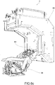
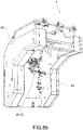
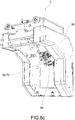
- the winding apparatus 4 comprises at least the winding unit 56 shaped to wind the yarn around a tube 8 so as to make a reel 12.
- Said winding apparatus 4 further comprises a doffing cart 60 having at least one support arm 64 configured to move said tube 8 and said reel 12.
- the winding apparatus 4 comprises at least one reading device 68 of the identification device 44 of the tube 8, so as to identify each individual tube 8 or reel 12.
- the reading device 68 is an electronic device configured to communicate with the radio frequency identification device 44, i.e. using an appropriate radio frequency, and to read the electronic identification code.
- the operations which can be performed by means of the reading device 68 are typically the inventory of the tags or identification devices 44, i.e. their reading and recognition, but also the rewriting of the electronic identification code (EPC).
- the reading device 68 can also act as a writing device so as to add additional information to the tag or identification devices 44 of the unique identification code alone.
- additional information may comprise, for example, characteristics of the winding unit 56 or events which occurred during the step of winding, such as the number of thread breaks, or parameters/operating conditions of the winding unit 56 during the formation of the reel 12.
- the reading device 68 of the identification device 44 is arranged on a support arm 64 of the doffing cart 60, so that the identification device 44 can be read when the support arm 64 moves the tube 8 or the reel 12.
- a reading device 68 of the identification device 44 at at least one winding unit 56, or also at each winding unit 56 of the winding apparatus 4.
- the reading device 68 of the identification device 44 is supported by a relative support arm 64 or reading arm and is provided with movement means 72 adapted to allow an oscillation of the reading device 68 about an oscillation axis lying on a plane perpendicular and incident to the axis of symmetry S-S of the tube 8.
- said oscillation occurs during the step of reading so that the identification code 44 can be read correctly and more quickly.
- the winding apparatus 4 comprises a reading device 68 of the identification device 44 at an unloading belt of the reels 12.
- the reading device 68 of the identification device 44 is calibrated to emit a power of less than 15 dBm.
- the reading device 68 of the identification device 44 is calibrated to emit a power between 8 and 12 dBm.
- Such power values are a trade-off which make it possible to read the concerned tag, i.e. the one applied to the tube to be identified, without having false readings from any other tags present on other parts of the winding unit 56, of the winding apparatus 4 or on other tubes adjacent to the concerned tube (e.g. because they are contained in bulk in a basket).
- the winding unit 56 and/or winding equipment 4 also comprises at least one processing and control unit (not shown) programmed to:
- the reading of said tag is improved or made faster by virtue of the relative movement between the tube 8 and thus of the identification device 44 and the reading device 68.
- the radiation diagram of the tag itself changes according to the relative orientation between the reading device 68 and the identification device.
- Such a relative movement can be done, for example, by rotating the tube 8 or the reel 12 about its axis of symmetry S-S and/or by tilting or swinging the reading device 68 around an oscillation axis lying on a plane perpendicular to, and incident with the axis of symmetry S-S of the tube 8.
- processing and control unit may be programmed to write information relating to the spinning unit and/or the operations carried out by the spinning unit on said tube/reel, and/or the operating conditions of the spinning unit during the formation of said reel 12 on the identification device 44 of a tube 8 or reel 12.
- said winding apparatus 4 comprises a data acquisition system 76 which stores the information relating to the processing steps of each reel 12 and associates it with the identification device 44 of each reel 12.
- said apparatus comprises a portable device 80 for reading the identification code 44 of each tube 8, said portable device being operatively connected with the data acquisition system 76 so as to reconstruct the stored data for the identification device 44 of each tube 8.
- the data acquisition system may also be connected to a remote terminal 84 which can be used by the user to display any further information provided by the data acquisition system 76.
- the winding apparatus works by implementing a winding method comprising the steps of:
- the method may comprise the step of: applying the RFID tags on the tubes 8 to be loaded on the baskets of the winder units 56, each tag having a unique EPC; loading a new tube 8 on the winding unit 56 by means of the cart 60, and during this process writing the following information on the identification device 44:
- the cart 60 communicates the EPC code of the identification device of the loaded tube 8 to the winding unit 56.
- the winding unit 56 at the end of the winding process of the reel 12, communicates the statistics, the alarms, the types of cuts made during the formation of reel 12, to the processing and control unit of the winding equipment 4 using the EPC code as a unique key to identify the collected information.
- the processing and control unit of the winding machine locally accumulates the data communicated by the winding units 56 concerning the formation of the reels 12 uniquely identifying them by virtue of the EPC provided by each tube 8.
- the processing and control unit sends the collected data to the external data acquisition system 76, which stores the data related to the formed reels 12, again using the EPC identification code.
- an external acquisition system makes it possible to retrieve the data related to the formation of a particular reel 12 according to the EPC.
- a portable reader 80 e.g. smartphone with RFID reader system
- the data acquisition system also makes it possible to give feedback on any problems which may have occurred during the use of reel 12 itself in weaving or, for example, in dyeing or knitting or more generally in the subsequent steps of processing of the reel 12.
- the present invention makes it possible to overcome the drawbacks of the prior art.
- the present invention makes it possible to overcome the limits of known winding systems.
- the individual reels can be traced in a complete and exhaustive manner so as to reconstruct their entire history, starting from their formation. It is, therefore, possible to keep track of the manufacturing batch (date and location), the winding machine and also the individual unit or winding head.
- the stored information makes it possible to uniquely identify the single reel and to reconstruct, for example, all the operations carried out by the head on the single reel, such as the number of cuts (and their splices), the exact length, and so on. This information can be read back by the user to reconstruct the history of the reel.
- the tag does not necessarily store all the information related to the making of the single reel but it can only store the (unique) identification code of the reel itself which will be associated to a database which contains additional information about, e.g. the winding machine, the single winding unit, the number of splices/cuts and so on.
- the reels can then be classified with a ranking or categorized in such a manner that they can be used for different purposes, for example, because of the respective quality resulting from the respective forming history.
- reels which have undergone a greater number of cuttings/reattachments may be used for weaving fabrics which are not intended to be visible in subsequent use (such as the cuffs of a shirt).
- the reels which have undergone fewer cuttings/reattachments may be used for weaving parts of fabrics intended to be always in view in the subsequent use, such as fabrics for shirt front parts.
- reels with a greater or lesser number of interruptions/reattachments may be destined to a different step of dyeing; for example, it will be possible to change the bath immersion time in the case of yarn-dyed reels.
- Another criterion according to which to modify the immersion time may be the exact length of the individual reel which obviously modifies the density of the thread.
- the information stored on the single reels may be useful to reconstruct the operating mode of the winding machine and the single winding heads/units, so that preventive maintenance can be carried out on the rotor heads/units themselves, for example.
Landscapes
- Engineering & Computer Science (AREA)
- Textile Engineering (AREA)
- Quality & Reliability (AREA)
- Storage Of Web-Like Or Filamentary Materials (AREA)
Applications Claiming Priority (1)
| Application Number | Priority Date | Filing Date | Title |
|---|---|---|---|
| IT102019000004575A IT201900004575A1 (it) | 2019-03-27 | 2019-03-27 | Tubetto per la tracciatura di una rocca, apparato di roccatura con dispositivo di tracciatura di una rocca e relativo metodo di roccatura |
Publications (2)
| Publication Number | Publication Date |
|---|---|
| EP3715295A1 true EP3715295A1 (de) | 2020-09-30 |
| EP3715295B1 EP3715295B1 (de) | 2025-07-23 |
Family
ID=67002252
Family Applications (1)
| Application Number | Title | Priority Date | Filing Date |
|---|---|---|---|
| EP20163492.0A Active EP3715295B1 (de) | 2019-03-27 | 2020-03-17 | Wickelvorrichtung mit spulenverfolgungsvorrichtung |
Country Status (3)
| Country | Link |
|---|---|
| EP (1) | EP3715295B1 (de) |
| CN (2) | CN111747227A (de) |
| IT (1) | IT201900004575A1 (de) |
Families Citing this family (2)
| Publication number | Priority date | Publication date | Assignee | Title |
|---|---|---|---|---|
| IT201900004575A1 (it) * | 2019-03-27 | 2020-09-27 | Savio Macch Tessili Spa | Tubetto per la tracciatura di una rocca, apparato di roccatura con dispositivo di tracciatura di una rocca e relativo metodo di roccatura |
| EP4271636B1 (de) * | 2020-12-30 | 2024-10-30 | Thema 2 S.R.L. | Automatische garnspulenlesevorrichtung mit rfid-etikett, zugehöriges system und verfolgungsverfahren |
Citations (3)
| Publication number | Priority date | Publication date | Assignee | Title |
|---|---|---|---|---|
| CH686156A5 (de) * | 1992-12-18 | 1996-01-15 | Luwa Ag Zellweger | Verfahren und Datentr{ger zur Materialidentifizierung und zum materialbegleitenden Datentransport in der Textilindustrie. |
| WO2003057610A1 (en) * | 2002-01-11 | 2003-07-17 | Scaglia Spa | Supporting element for winding yarns |
| WO2006134783A1 (ja) * | 2005-06-15 | 2006-12-21 | Murata Kikai Kabushiki Kaisha | 巻き糸パッケージの巻取り管および巻き糸パッケージの管理装置 |
Family Cites Families (7)
| Publication number | Priority date | Publication date | Assignee | Title |
|---|---|---|---|---|
| US5269478A (en) * | 1991-05-23 | 1993-12-14 | Murata Kikai Kabushiki Kaisha | Bobbin trace system |
| DE4209219B4 (de) * | 1992-03-21 | 2005-08-04 | Saurer Gmbh & Co. Kg | Spulmaschine mit einem geschlossenen Transportsystem für Spulentransportteller |
| ITVI20030205A1 (it) * | 2003-10-15 | 2005-04-16 | Nuova Saccardo S C A R L | Dispositivo per il supporto e/o il contenimento di |
| JP4760145B2 (ja) * | 2005-06-03 | 2011-08-31 | 村田機械株式会社 | 巻取チューブのラベル貼付装置および自動ワインダー |
| JP2011020838A (ja) * | 2009-07-17 | 2011-02-03 | Murata Machinery Ltd | 自動ワインダの繊維機械管理システム及び自動ワインダ |
| EP3594138A3 (de) * | 2015-06-23 | 2020-04-29 | Tetra Laval Holdings & Finance S.A. | Mit einem verpackungsmaterial ausgestattete rolle und füllmaschine zum füllen von verpackungsmaterial mit einem lebensmittelprodukt |
| IT201900004575A1 (it) * | 2019-03-27 | 2020-09-27 | Savio Macch Tessili Spa | Tubetto per la tracciatura di una rocca, apparato di roccatura con dispositivo di tracciatura di una rocca e relativo metodo di roccatura |
-
2019
- 2019-03-27 IT IT102019000004575A patent/IT201900004575A1/it unknown
-
2020
- 2020-03-17 EP EP20163492.0A patent/EP3715295B1/de active Active
- 2020-03-24 CN CN202010213330.4A patent/CN111747227A/zh active Pending
- 2020-03-24 CN CN202020390034.7U patent/CN212269105U/zh active Active
Patent Citations (3)
| Publication number | Priority date | Publication date | Assignee | Title |
|---|---|---|---|---|
| CH686156A5 (de) * | 1992-12-18 | 1996-01-15 | Luwa Ag Zellweger | Verfahren und Datentr{ger zur Materialidentifizierung und zum materialbegleitenden Datentransport in der Textilindustrie. |
| WO2003057610A1 (en) * | 2002-01-11 | 2003-07-17 | Scaglia Spa | Supporting element for winding yarns |
| WO2006134783A1 (ja) * | 2005-06-15 | 2006-12-21 | Murata Kikai Kabushiki Kaisha | 巻き糸パッケージの巻取り管および巻き糸パッケージの管理装置 |
Also Published As
| Publication number | Publication date |
|---|---|
| CN111747227A (zh) | 2020-10-09 |
| CN212269105U (zh) | 2021-01-01 |
| IT201900004575A1 (it) | 2020-09-27 |
| EP3715295B1 (de) | 2025-07-23 |
Similar Documents
| Publication | Publication Date | Title |
|---|---|---|
| EP3715295B1 (de) | Wickelvorrichtung mit spulenverfolgungsvorrichtung | |
| US5287692A (en) | Transport medium for yarn or the like | |
| EP2455318B1 (de) | Automatischer wickler mit einem verwaltungssystem | |
| EP3626660B1 (de) | Spinnanlage und verfahren zur verhinderung von wicklungen | |
| EP3305953B1 (de) | Verbundsystem, spulmaschine und spulverfahren | |
| WO2016194484A1 (ja) | 糸巻取システム、自動ワインダ、精紡機及び糸巻取方法 | |
| CN108285062B (zh) | 纱线信息取得装置、纱线卷取机以及纤维机械系统 | |
| CH686156A5 (de) | Verfahren und Datentr{ger zur Materialidentifizierung und zum materialbegleitenden Datentransport in der Textilindustrie. | |
| CN113795446A (zh) | 纺织机 | |
| JP2021525838A (ja) | 自動のリング精紡設備及びリング精紡設備を自動で運転する方法 | |
| EP0638674A1 (de) | Verfahren und Vorrichtung zur Qualitätsüberwachung eines gezwirnten Garns | |
| CN109384097A (zh) | 从纱线中清除纱线瑕疵的装置 | |
| WO2006134783A1 (ja) | 巻き糸パッケージの巻取り管および巻き糸パッケージの管理装置 | |
| JP7305681B2 (ja) | 複数の糸を溶融紡糸し、巻き取るための方法および装置 | |
| CN109137167A (zh) | 一种通过电子标签实现粗纱筒管定位的追溯装置及方法 | |
| EP3919426B1 (de) | Garnwickelmaschine und spinnsystem | |
| JP2000344419A (ja) | コップの紡糸位置を特定する方法 | |
| JP2018177449A (ja) | 管理装置及び糸巻取システム | |
| EP3950553B1 (de) | Verfahren zum erkennen der anwesenheit und/oder nachführung einer spulenhalterplatte in einer spulmaschine oder ringspinnmaschine, spulenhalterplatte für eine spulmaschine oder ringspinnmaschine sowie vorrichtung zur erkennung der anwesenheit und/oder nachführung einer spule in einer spulmaschine oder ringspinnmaschine | |
| JP2001503658A (ja) | 巻き直し工程の間に糸毎に固有のデータを送信し、文書化対象となる本縫いの縫目を2本の糸で形成するための方法および装置 | |
| CN109117907A (zh) | 一种粗纱机纱管追溯装置及方法 | |
| US20250236994A1 (en) | An electronic device for locating a functional disorder within a spinning and winding section of a spinning mill and a method for locating the same | |
| WO2005037701A1 (en) | Device for supporting and/or containing roving or yarn or textile tape in general and related identification system | |
| ES2993375T3 (en) | Automatic thread reel reading device with rfid tag, related system and tracking method | |
| CN214200135U (zh) | 一种纱线质量自动追踪装置 |
Legal Events
| Date | Code | Title | Description |
|---|---|---|---|
| PUAI | Public reference made under article 153(3) epc to a published international application that has entered the european phase |
Free format text: ORIGINAL CODE: 0009012 |
|
| STAA | Information on the status of an ep patent application or granted ep patent |
Free format text: STATUS: THE APPLICATION HAS BEEN PUBLISHED |
|
| AK | Designated contracting states |
Kind code of ref document: A1 Designated state(s): AL AT BE BG CH CY CZ DE DK EE ES FI FR GB GR HR HU IE IS IT LI LT LU LV MC MK MT NL NO PL PT RO RS SE SI SK SM TR |
|
| AX | Request for extension of the european patent |
Extension state: BA ME |
|
| STAA | Information on the status of an ep patent application or granted ep patent |
Free format text: STATUS: REQUEST FOR EXAMINATION WAS MADE |
|
| 17P | Request for examination filed |
Effective date: 20210317 |
|
| RBV | Designated contracting states (corrected) |
Designated state(s): AL AT BE BG CH CY CZ DE DK EE ES FI FR GB GR HR HU IE IS IT LI LT LU LV MC MK MT NL NO PL PT RO RS SE SI SK SM TR |
|
| STAA | Information on the status of an ep patent application or granted ep patent |
Free format text: STATUS: EXAMINATION IS IN PROGRESS |
|
| 17Q | First examination report despatched |
Effective date: 20220804 |
|
| P01 | Opt-out of the competence of the unified patent court (upc) registered |
Effective date: 20230526 |
|
| GRAP | Despatch of communication of intention to grant a patent |
Free format text: ORIGINAL CODE: EPIDOSNIGR1 |
|
| STAA | Information on the status of an ep patent application or granted ep patent |
Free format text: STATUS: GRANT OF PATENT IS INTENDED |
|
| INTG | Intention to grant announced |
Effective date: 20250220 |
|
| GRAS | Grant fee paid |
Free format text: ORIGINAL CODE: EPIDOSNIGR3 |
|
| GRAA | (expected) grant |
Free format text: ORIGINAL CODE: 0009210 |
|
| STAA | Information on the status of an ep patent application or granted ep patent |
Free format text: STATUS: THE PATENT HAS BEEN GRANTED |
|
| AK | Designated contracting states |
Kind code of ref document: B1 Designated state(s): AL AT BE BG CH CY CZ DE DK EE ES FI FR GB GR HR HU IE IS IT LI LT LU LV MC MK MT NL NO PL PT RO RS SE SI SK SM TR |
|
| REG | Reference to a national code |
Ref country code: GB Ref legal event code: FG4D |
|
| REG | Reference to a national code |
Ref country code: CH Ref legal event code: EP |
|
| REG | Reference to a national code |
Ref country code: DE Ref legal event code: R096 Ref document number: 602020054879 Country of ref document: DE |
|
| REG | Reference to a national code |
Ref country code: IE Ref legal event code: FG4D |
|
| REG | Reference to a national code |
Ref country code: NL Ref legal event code: MP Effective date: 20250723 |
|
| PG25 | Lapsed in a contracting state [announced via postgrant information from national office to epo] |
Ref country code: PT Free format text: LAPSE BECAUSE OF FAILURE TO SUBMIT A TRANSLATION OF THE DESCRIPTION OR TO PAY THE FEE WITHIN THE PRESCRIBED TIME-LIMIT Effective date: 20251124 |
|
| PG25 | Lapsed in a contracting state [announced via postgrant information from national office to epo] |
Ref country code: NL Free format text: LAPSE BECAUSE OF FAILURE TO SUBMIT A TRANSLATION OF THE DESCRIPTION OR TO PAY THE FEE WITHIN THE PRESCRIBED TIME-LIMIT Effective date: 20250723 |
|
| REG | Reference to a national code |
Ref country code: AT Ref legal event code: MK05 Ref document number: 1816265 Country of ref document: AT Kind code of ref document: T Effective date: 20250723 |
|
| PG25 | Lapsed in a contracting state [announced via postgrant information from national office to epo] |
Ref country code: IS Free format text: LAPSE BECAUSE OF FAILURE TO SUBMIT A TRANSLATION OF THE DESCRIPTION OR TO PAY THE FEE WITHIN THE PRESCRIBED TIME-LIMIT Effective date: 20251123 |
|
| PG25 | Lapsed in a contracting state [announced via postgrant information from national office to epo] |
Ref country code: NO Free format text: LAPSE BECAUSE OF FAILURE TO SUBMIT A TRANSLATION OF THE DESCRIPTION OR TO PAY THE FEE WITHIN THE PRESCRIBED TIME-LIMIT Effective date: 20251023 |
|
| REG | Reference to a national code |
Ref country code: LT Ref legal event code: MG9D |
|
| PG25 | Lapsed in a contracting state [announced via postgrant information from national office to epo] |
Ref country code: AT Free format text: LAPSE BECAUSE OF FAILURE TO SUBMIT A TRANSLATION OF THE DESCRIPTION OR TO PAY THE FEE WITHIN THE PRESCRIBED TIME-LIMIT Effective date: 20250723 |
|
| PG25 | Lapsed in a contracting state [announced via postgrant information from national office to epo] |
Ref country code: FI Free format text: LAPSE BECAUSE OF FAILURE TO SUBMIT A TRANSLATION OF THE DESCRIPTION OR TO PAY THE FEE WITHIN THE PRESCRIBED TIME-LIMIT Effective date: 20250723 |
|
| PG25 | Lapsed in a contracting state [announced via postgrant information from national office to epo] |
Ref country code: HR Free format text: LAPSE BECAUSE OF FAILURE TO SUBMIT A TRANSLATION OF THE DESCRIPTION OR TO PAY THE FEE WITHIN THE PRESCRIBED TIME-LIMIT Effective date: 20250723 |
|
| PG25 | Lapsed in a contracting state [announced via postgrant information from national office to epo] |
Ref country code: GR Free format text: LAPSE BECAUSE OF FAILURE TO SUBMIT A TRANSLATION OF THE DESCRIPTION OR TO PAY THE FEE WITHIN THE PRESCRIBED TIME-LIMIT Effective date: 20251024 |
|
| PG25 | Lapsed in a contracting state [announced via postgrant information from national office to epo] |
Ref country code: SE Free format text: LAPSE BECAUSE OF FAILURE TO SUBMIT A TRANSLATION OF THE DESCRIPTION OR TO PAY THE FEE WITHIN THE PRESCRIBED TIME-LIMIT Effective date: 20250723 |
|
| PG25 | Lapsed in a contracting state [announced via postgrant information from national office to epo] |
Ref country code: LV Free format text: LAPSE BECAUSE OF FAILURE TO SUBMIT A TRANSLATION OF THE DESCRIPTION OR TO PAY THE FEE WITHIN THE PRESCRIBED TIME-LIMIT Effective date: 20250723 |
|
| PG25 | Lapsed in a contracting state [announced via postgrant information from national office to epo] |
Ref country code: BG Free format text: LAPSE BECAUSE OF FAILURE TO SUBMIT A TRANSLATION OF THE DESCRIPTION OR TO PAY THE FEE WITHIN THE PRESCRIBED TIME-LIMIT Effective date: 20250723 Ref country code: PL Free format text: LAPSE BECAUSE OF FAILURE TO SUBMIT A TRANSLATION OF THE DESCRIPTION OR TO PAY THE FEE WITHIN THE PRESCRIBED TIME-LIMIT Effective date: 20250723 |
|
| PG25 | Lapsed in a contracting state [announced via postgrant information from national office to epo] |
Ref country code: RS Free format text: LAPSE BECAUSE OF FAILURE TO SUBMIT A TRANSLATION OF THE DESCRIPTION OR TO PAY THE FEE WITHIN THE PRESCRIBED TIME-LIMIT Effective date: 20251023 |
|
| PG25 | Lapsed in a contracting state [announced via postgrant information from national office to epo] |
Ref country code: ES Free format text: LAPSE BECAUSE OF FAILURE TO SUBMIT A TRANSLATION OF THE DESCRIPTION OR TO PAY THE FEE WITHIN THE PRESCRIBED TIME-LIMIT Effective date: 20250723 |
|
| PG25 | Lapsed in a contracting state [announced via postgrant information from national office to epo] |
Ref country code: SM Free format text: LAPSE BECAUSE OF FAILURE TO SUBMIT A TRANSLATION OF THE DESCRIPTION OR TO PAY THE FEE WITHIN THE PRESCRIBED TIME-LIMIT Effective date: 20250723 |
|
| PG25 | Lapsed in a contracting state [announced via postgrant information from national office to epo] |
Ref country code: DK Free format text: LAPSE BECAUSE OF FAILURE TO SUBMIT A TRANSLATION OF THE DESCRIPTION OR TO PAY THE FEE WITHIN THE PRESCRIBED TIME-LIMIT Effective date: 20250723 |
|
| PGFP | Annual fee paid to national office [announced via postgrant information from national office to epo] |
Ref country code: DE Payment date: 20260325 Year of fee payment: 7 |
|
| PGFP | Annual fee paid to national office [announced via postgrant information from national office to epo] |
Ref country code: IT Payment date: 20260107 Year of fee payment: 7 |
|
| PGFP | Annual fee paid to national office [announced via postgrant information from national office to epo] |
Ref country code: TR Payment date: 20260314 Year of fee payment: 7 |
|
| PG25 | Lapsed in a contracting state [announced via postgrant information from national office to epo] |
Ref country code: CZ Free format text: LAPSE BECAUSE OF FAILURE TO SUBMIT A TRANSLATION OF THE DESCRIPTION OR TO PAY THE FEE WITHIN THE PRESCRIBED TIME-LIMIT Effective date: 20250723 |
|
| PG25 | Lapsed in a contracting state [announced via postgrant information from national office to epo] |
Ref country code: SK Free format text: LAPSE BECAUSE OF FAILURE TO SUBMIT A TRANSLATION OF THE DESCRIPTION OR TO PAY THE FEE WITHIN THE PRESCRIBED TIME-LIMIT Effective date: 20250723 Ref country code: EE Free format text: LAPSE BECAUSE OF FAILURE TO SUBMIT A TRANSLATION OF THE DESCRIPTION OR TO PAY THE FEE WITHIN THE PRESCRIBED TIME-LIMIT Effective date: 20250723 |