EP3715501B1 - Reaktionsrohr, substratverarbeitungsvorrichtung und verfahren zur herstellung eines halbleiterbauelements - Google Patents
Reaktionsrohr, substratverarbeitungsvorrichtung und verfahren zur herstellung eines halbleiterbauelements Download PDFInfo
- Publication number
- EP3715501B1 EP3715501B1 EP20165340.9A EP20165340A EP3715501B1 EP 3715501 B1 EP3715501 B1 EP 3715501B1 EP 20165340 A EP20165340 A EP 20165340A EP 3715501 B1 EP3715501 B1 EP 3715501B1
- Authority
- EP
- European Patent Office
- Prior art keywords
- preheating
- reaction tube
- preheating portion
- gas
- gas introduction
- Prior art date
- Legal status (The legal status is an assumption and is not a legal conclusion. Google has not performed a legal analysis and makes no representation as to the accuracy of the status listed.)
- Active
Links
Images




Classifications
-
- H—ELECTRICITY
- H01—ELECTRIC ELEMENTS
- H01J—ELECTRIC DISCHARGE TUBES OR DISCHARGE LAMPS
- H01J37/00—Discharge tubes with provision for introducing objects or material to be exposed to the discharge, e.g. for the purpose of examination or processing thereof
- H01J37/32—Gas-filled discharge tubes
- H01J37/32431—Constructional details of the reactor
- H01J37/3244—Gas supply means
- H01J37/32449—Gas control, e.g. control of the gas flow
-
- C—CHEMISTRY; METALLURGY
- C23—COATING METALLIC MATERIAL; COATING MATERIAL WITH METALLIC MATERIAL; CHEMICAL SURFACE TREATMENT; DIFFUSION TREATMENT OF METALLIC MATERIAL; COATING BY VACUUM EVAPORATION, BY SPUTTERING, BY ION IMPLANTATION OR BY CHEMICAL VAPOUR DEPOSITION, IN GENERAL; INHIBITING CORROSION OF METALLIC MATERIAL OR INCRUSTATION IN GENERAL
- C23C—COATING METALLIC MATERIAL; COATING MATERIAL WITH METALLIC MATERIAL; SURFACE TREATMENT OF METALLIC MATERIAL BY DIFFUSION INTO THE SURFACE, BY CHEMICAL CONVERSION OR SUBSTITUTION; COATING BY VACUUM EVAPORATION, BY SPUTTERING, BY ION IMPLANTATION OR BY CHEMICAL VAPOUR DEPOSITION, IN GENERAL
- C23C16/00—Chemical coating by decomposition of gaseous compounds, without leaving reaction products of surface material in the coating, i.e. chemical vapour deposition [CVD] processes
- C23C16/44—Chemical coating by decomposition of gaseous compounds, without leaving reaction products of surface material in the coating, i.e. chemical vapour deposition [CVD] processes characterised by the method of coating
- C23C16/4412—Details relating to the exhausts, e.g. pumps, filters, scrubbers, particle traps
-
- C—CHEMISTRY; METALLURGY
- C23—COATING METALLIC MATERIAL; COATING MATERIAL WITH METALLIC MATERIAL; CHEMICAL SURFACE TREATMENT; DIFFUSION TREATMENT OF METALLIC MATERIAL; COATING BY VACUUM EVAPORATION, BY SPUTTERING, BY ION IMPLANTATION OR BY CHEMICAL VAPOUR DEPOSITION, IN GENERAL; INHIBITING CORROSION OF METALLIC MATERIAL OR INCRUSTATION IN GENERAL
- C23C—COATING METALLIC MATERIAL; COATING MATERIAL WITH METALLIC MATERIAL; SURFACE TREATMENT OF METALLIC MATERIAL BY DIFFUSION INTO THE SURFACE, BY CHEMICAL CONVERSION OR SUBSTITUTION; COATING BY VACUUM EVAPORATION, BY SPUTTERING, BY ION IMPLANTATION OR BY CHEMICAL VAPOUR DEPOSITION, IN GENERAL
- C23C16/00—Chemical coating by decomposition of gaseous compounds, without leaving reaction products of surface material in the coating, i.e. chemical vapour deposition [CVD] processes
- C23C16/44—Chemical coating by decomposition of gaseous compounds, without leaving reaction products of surface material in the coating, i.e. chemical vapour deposition [CVD] processes characterised by the method of coating
- C23C16/455—Chemical coating by decomposition of gaseous compounds, without leaving reaction products of surface material in the coating, i.e. chemical vapour deposition [CVD] processes characterised by the method of coating characterised by the method used for introducing gases into reaction chamber or for modifying gas flows in reaction chamber
- C23C16/45523—Pulsed gas flow or change of composition over time
- C23C16/45525—Atomic layer deposition [ALD]
- C23C16/45544—Atomic layer deposition [ALD] characterized by the apparatus
- C23C16/45546—Atomic layer deposition [ALD] characterized by the apparatus specially adapted for a substrate stack in the ALD reactor
-
- C—CHEMISTRY; METALLURGY
- C23—COATING METALLIC MATERIAL; COATING MATERIAL WITH METALLIC MATERIAL; CHEMICAL SURFACE TREATMENT; DIFFUSION TREATMENT OF METALLIC MATERIAL; COATING BY VACUUM EVAPORATION, BY SPUTTERING, BY ION IMPLANTATION OR BY CHEMICAL VAPOUR DEPOSITION, IN GENERAL; INHIBITING CORROSION OF METALLIC MATERIAL OR INCRUSTATION IN GENERAL
- C23C—COATING METALLIC MATERIAL; COATING MATERIAL WITH METALLIC MATERIAL; SURFACE TREATMENT OF METALLIC MATERIAL BY DIFFUSION INTO THE SURFACE, BY CHEMICAL CONVERSION OR SUBSTITUTION; COATING BY VACUUM EVAPORATION, BY SPUTTERING, BY ION IMPLANTATION OR BY CHEMICAL VAPOUR DEPOSITION, IN GENERAL
- C23C16/00—Chemical coating by decomposition of gaseous compounds, without leaving reaction products of surface material in the coating, i.e. chemical vapour deposition [CVD] processes
- C23C16/44—Chemical coating by decomposition of gaseous compounds, without leaving reaction products of surface material in the coating, i.e. chemical vapour deposition [CVD] processes characterised by the method of coating
- C23C16/455—Chemical coating by decomposition of gaseous compounds, without leaving reaction products of surface material in the coating, i.e. chemical vapour deposition [CVD] processes characterised by the method of coating characterised by the method used for introducing gases into reaction chamber or for modifying gas flows in reaction chamber
- C23C16/45563—Gas nozzles
- C23C16/4557—Heated nozzles
-
- C—CHEMISTRY; METALLURGY
- C23—COATING METALLIC MATERIAL; COATING MATERIAL WITH METALLIC MATERIAL; CHEMICAL SURFACE TREATMENT; DIFFUSION TREATMENT OF METALLIC MATERIAL; COATING BY VACUUM EVAPORATION, BY SPUTTERING, BY ION IMPLANTATION OR BY CHEMICAL VAPOUR DEPOSITION, IN GENERAL; INHIBITING CORROSION OF METALLIC MATERIAL OR INCRUSTATION IN GENERAL
- C23C—COATING METALLIC MATERIAL; COATING MATERIAL WITH METALLIC MATERIAL; SURFACE TREATMENT OF METALLIC MATERIAL BY DIFFUSION INTO THE SURFACE, BY CHEMICAL CONVERSION OR SUBSTITUTION; COATING BY VACUUM EVAPORATION, BY SPUTTERING, BY ION IMPLANTATION OR BY CHEMICAL VAPOUR DEPOSITION, IN GENERAL
- C23C16/00—Chemical coating by decomposition of gaseous compounds, without leaving reaction products of surface material in the coating, i.e. chemical vapour deposition [CVD] processes
- C23C16/44—Chemical coating by decomposition of gaseous compounds, without leaving reaction products of surface material in the coating, i.e. chemical vapour deposition [CVD] processes characterised by the method of coating
- C23C16/455—Chemical coating by decomposition of gaseous compounds, without leaving reaction products of surface material in the coating, i.e. chemical vapour deposition [CVD] processes characterised by the method of coating characterised by the method used for introducing gases into reaction chamber or for modifying gas flows in reaction chamber
- C23C16/45563—Gas nozzles
- C23C16/45578—Elongated nozzles, tubes with holes
-
- C—CHEMISTRY; METALLURGY
- C23—COATING METALLIC MATERIAL; COATING MATERIAL WITH METALLIC MATERIAL; CHEMICAL SURFACE TREATMENT; DIFFUSION TREATMENT OF METALLIC MATERIAL; COATING BY VACUUM EVAPORATION, BY SPUTTERING, BY ION IMPLANTATION OR BY CHEMICAL VAPOUR DEPOSITION, IN GENERAL; INHIBITING CORROSION OF METALLIC MATERIAL OR INCRUSTATION IN GENERAL
- C23C—COATING METALLIC MATERIAL; COATING MATERIAL WITH METALLIC MATERIAL; SURFACE TREATMENT OF METALLIC MATERIAL BY DIFFUSION INTO THE SURFACE, BY CHEMICAL CONVERSION OR SUBSTITUTION; COATING BY VACUUM EVAPORATION, BY SPUTTERING, BY ION IMPLANTATION OR BY CHEMICAL VAPOUR DEPOSITION, IN GENERAL
- C23C16/00—Chemical coating by decomposition of gaseous compounds, without leaving reaction products of surface material in the coating, i.e. chemical vapour deposition [CVD] processes
- C23C16/44—Chemical coating by decomposition of gaseous compounds, without leaving reaction products of surface material in the coating, i.e. chemical vapour deposition [CVD] processes characterised by the method of coating
- C23C16/52—Controlling or regulating the coating process
-
- C—CHEMISTRY; METALLURGY
- C30—CRYSTAL GROWTH
- C30B—SINGLE-CRYSTAL GROWTH; UNIDIRECTIONAL SOLIDIFICATION OF EUTECTIC MATERIAL OR UNIDIRECTIONAL DEMIXING OF EUTECTOID MATERIAL; REFINING BY ZONE-MELTING OF MATERIAL; PRODUCTION OF A HOMOGENEOUS POLYCRYSTALLINE MATERIAL WITH DEFINED STRUCTURE; SINGLE CRYSTALS OR HOMOGENEOUS POLYCRYSTALLINE MATERIAL WITH DEFINED STRUCTURE; AFTER-TREATMENT OF SINGLE CRYSTALS OR A HOMOGENEOUS POLYCRYSTALLINE MATERIAL WITH DEFINED STRUCTURE; APPARATUS THEREFOR
- C30B25/00—Single-crystal growth by chemical reaction of reactive gases, e.g. chemical vapour-deposition growth
- C30B25/02—Epitaxial-layer growth
- C30B25/14—Feed and outlet means for the gases; Modifying the flow of the reactive gases
-
- F—MECHANICAL ENGINEERING; LIGHTING; HEATING; WEAPONS; BLASTING
- F27—FURNACES; KILNS; OVENS; RETORTS
- F27B—FURNACES, KILNS, OVENS OR RETORTS IN GENERAL; OPEN SINTERING OR LIKE APPARATUS
- F27B17/00—Furnaces of a kind not covered by any of groups F27B1/00 - F27B15/00
- F27B17/0016—Chamber type furnaces
- F27B17/0025—Chamber type furnaces specially adapted for treating semiconductor wafers
-
- H—ELECTRICITY
- H10—SEMICONDUCTOR DEVICES; ELECTRIC SOLID-STATE DEVICES NOT OTHERWISE PROVIDED FOR
- H10P—GENERIC PROCESSES OR APPARATUS FOR THE MANUFACTURE OR TREATMENT OF DEVICES COVERED BY CLASS H10
- H10P72/00—Handling or holding of wafers, substrates or devices during manufacture or treatment thereof
- H10P72/04—Apparatus for manufacture or treatment
- H10P72/0402—Apparatus for fluid treatment
-
- H—ELECTRICITY
- H10—SEMICONDUCTOR DEVICES; ELECTRIC SOLID-STATE DEVICES NOT OTHERWISE PROVIDED FOR
- H10P—GENERIC PROCESSES OR APPARATUS FOR THE MANUFACTURE OR TREATMENT OF DEVICES COVERED BY CLASS H10
- H10P72/00—Handling or holding of wafers, substrates or devices during manufacture or treatment thereof
- H10P72/04—Apparatus for manufacture or treatment
- H10P72/0431—Apparatus for thermal treatment
-
- H—ELECTRICITY
- H10—SEMICONDUCTOR DEVICES; ELECTRIC SOLID-STATE DEVICES NOT OTHERWISE PROVIDED FOR
- H10P—GENERIC PROCESSES OR APPARATUS FOR THE MANUFACTURE OR TREATMENT OF DEVICES COVERED BY CLASS H10
- H10P72/00—Handling or holding of wafers, substrates or devices during manufacture or treatment thereof
- H10P72/04—Apparatus for manufacture or treatment
- H10P72/0431—Apparatus for thermal treatment
- H10P72/0432—Apparatus for thermal treatment mainly by conduction
-
- H—ELECTRICITY
- H10—SEMICONDUCTOR DEVICES; ELECTRIC SOLID-STATE DEVICES NOT OTHERWISE PROVIDED FOR
- H10P—GENERIC PROCESSES OR APPARATUS FOR THE MANUFACTURE OR TREATMENT OF DEVICES COVERED BY CLASS H10
- H10P72/00—Handling or holding of wafers, substrates or devices during manufacture or treatment thereof
- H10P72/04—Apparatus for manufacture or treatment
- H10P72/0431—Apparatus for thermal treatment
- H10P72/0434—Apparatus for thermal treatment mainly by convection
-
- H—ELECTRICITY
- H10—SEMICONDUCTOR DEVICES; ELECTRIC SOLID-STATE DEVICES NOT OTHERWISE PROVIDED FOR
- H10P—GENERIC PROCESSES OR APPARATUS FOR THE MANUFACTURE OR TREATMENT OF DEVICES COVERED BY CLASS H10
- H10P72/00—Handling or holding of wafers, substrates or devices during manufacture or treatment thereof
- H10P72/04—Apparatus for manufacture or treatment
- H10P72/0451—Apparatus for manufacturing or treating in a plurality of work-stations
- H10P72/0462—Apparatus for manufacturing or treating in a plurality of work-stations characterised by the construction of the processing chambers, e.g. modular processing chambers
-
- H—ELECTRICITY
- H10—SEMICONDUCTOR DEVICES; ELECTRIC SOLID-STATE DEVICES NOT OTHERWISE PROVIDED FOR
- H10P—GENERIC PROCESSES OR APPARATUS FOR THE MANUFACTURE OR TREATMENT OF DEVICES COVERED BY CLASS H10
- H10P72/00—Handling or holding of wafers, substrates or devices during manufacture or treatment thereof
- H10P72/06—Apparatus for monitoring, sorting, marking, testing or measuring
- H10P72/0602—Temperature monitoring
-
- H—ELECTRICITY
- H10—SEMICONDUCTOR DEVICES; ELECTRIC SOLID-STATE DEVICES NOT OTHERWISE PROVIDED FOR
- H10P—GENERIC PROCESSES OR APPARATUS FOR THE MANUFACTURE OR TREATMENT OF DEVICES COVERED BY CLASS H10
- H10P72/00—Handling or holding of wafers, substrates or devices during manufacture or treatment thereof
- H10P72/06—Apparatus for monitoring, sorting, marking, testing or measuring
- H10P72/0604—Process monitoring, e.g. flow or thickness monitoring
-
- H—ELECTRICITY
- H10—SEMICONDUCTOR DEVICES; ELECTRIC SOLID-STATE DEVICES NOT OTHERWISE PROVIDED FOR
- H10P—GENERIC PROCESSES OR APPARATUS FOR THE MANUFACTURE OR TREATMENT OF DEVICES COVERED BY CLASS H10
- H10P72/00—Handling or holding of wafers, substrates or devices during manufacture or treatment thereof
- H10P72/10—Handling or holding of wafers, substrates or devices during manufacture or treatment thereof using carriers specially adapted therefor, e.g. front opening unified pods [FOUP]
- H10P72/12—Vertical boat type carrier whereby the substrates are horizontally supported, e.g. comprising rod-shaped elements
-
- H—ELECTRICITY
- H10—SEMICONDUCTOR DEVICES; ELECTRIC SOLID-STATE DEVICES NOT OTHERWISE PROVIDED FOR
- H10P—GENERIC PROCESSES OR APPARATUS FOR THE MANUFACTURE OR TREATMENT OF DEVICES COVERED BY CLASS H10
- H10P72/00—Handling or holding of wafers, substrates or devices during manufacture or treatment thereof
- H10P72/10—Handling or holding of wafers, substrates or devices during manufacture or treatment thereof using carriers specially adapted therefor, e.g. front opening unified pods [FOUP]
- H10P72/14—Vertical carrier comprising wall type elements whereby the substrates are horizontally supported, e.g. comprising sidewalls
-
- H—ELECTRICITY
- H10—SEMICONDUCTOR DEVICES; ELECTRIC SOLID-STATE DEVICES NOT OTHERWISE PROVIDED FOR
- H10P—GENERIC PROCESSES OR APPARATUS FOR THE MANUFACTURE OR TREATMENT OF DEVICES COVERED BY CLASS H10
- H10P72/00—Handling or holding of wafers, substrates or devices during manufacture or treatment thereof
- H10P72/30—Handling or holding of wafers, substrates or devices during manufacture or treatment thereof for conveying, e.g. between different workstations
- H10P72/33—Handling or holding of wafers, substrates or devices during manufacture or treatment thereof for conveying, e.g. between different workstations into and out of processing chamber
- H10P72/3312—Vertical transfer of a batch of workpieces
Definitions
- the present disclosure relates to a reaction tube, a substrate processing apparatus and a method of manufacturing a semiconductor device.
- the present disclosure relates to a reaction tube, a substrate processing apparatus and a method of manufacturing a semiconductor device.
- a substrate processing apparatus may be configured to perform a process such as an oxidation process and a diffusion process.
- a gas such as a process gas is introduced through a gas introduction port provided at a bottom of a reaction tube of the substrate processing apparatus, and then is supplied into a reaction chamber (also referred to as a "process chamber").
- a reaction chamber also referred to as a "process chamber”
- Patent Document 1 and Patent Document 2 described below a space where the gas is temporarily stored to adjust a pressure of the gas is provided at the reaction tube, and the gas is supplied into the reaction chamber through the space.
- a preheating cylinder is provided below a substrate processing region of a substrate retainer and a gas introduction portion of the substrate processing apparatus, and the gas introduced through the gas introduction portion flows upward via the preheating cylinder.
- the gas introduced through the gas introduction portion may pass through the pipe arranged on a side surface of the substrate processing region without sufficiently heated to a desired temperature.
- a temperature of an outer periphery of a lower portion of the substrate processing region may decrease, and thus processing results between substrates accommodated in the substrate processing region may vary.
- Described herein is a technique capable of reducing a difference in processing results between substrates arranged in a substrate processing region.
- a reaction tube provided therein with a process chamber and heated by a heater provided therearound including: a gas introduction portion provided at a lower end and through which a process gas is introduced; a first supplier provided along a side surface at least at a position facing a substrate processing region where a plurality of substrates are processed; and a preheating portion provided at a position lower than the substrate processing region, the preheating portion including: a first preheating portion extending in a direction from the gas introduction portion toward a ceiling; and a second preheating portion extending in a direction perpendicular to the direction from the gas introduction portion toward the ceiling, wherein the preheating portion is configured to connect the gas introduction portion with the first supplier by combining the first preheating portion and the second preheating portion, and wherein a cross-sectional shape of the first preheating portion is different from that of the second preheating portion.
- a substrate processing apparatus (also simply referred to as a "processing apparatus”) 100 is configured to process a semiconductor wafer.
- the substrate processing apparatus 100 is configured to perform a substrate processing such as a film-forming process of forming an oxide film on the semiconductor wafer, a diffusion process on the semiconductor wafer and a CVD process on the semiconductor wafer.
- the semiconductor wafer (hereinafter, also simply referred to as a "wafer") 200 serving as a substrate is made of a semiconductor material such as silicon (Si).
- a FOUP (front opening unified pod) 110 is used as a carrier (container) of accommodating and transporting (transferring) a plurality of wafers including the wafer 200.
- the processing apparatus 100 includes a housing 111.
- a maintenance space is provided at a lower front portion of a front wall 111a of the housing 111.
- Front maintenance doors 104a and 104b configured to open and close the maintenance space are provided at the lower front portion of the front wall 111a of the housing 111.
- a pod loading/unloading port 112 is provided at the front wall 111a of the housing 111 so as to communicate with an inside and an outside of the housing 111.
- the FOUP (hereinafter, also referred to as a "pod") 110 may be transferred (loaded) into and transferred (unloaded) out of the housing 111 through the pod loading/unloading port 112.
- a front shutter 113 is configured to open and close the pod loading/unloading port 112.
- a loading port (also referred to as a "load port shelf) 114 is provided in front of the pod loading/unloading port 112.
- the pod 110 is aligned while placed on the load port shelf 114.
- the pod 110 is loaded onto or unloaded from the load port shelf 114 by an in-process transfer apparatus (not shown).
- An accommodating shelf 105 is provided over a substantially center portion in a front-rear direction in the housing 111.
- the accommodating shelf 105 is configured to hold (store) the pod 110 and is rotatable.
- the accommodating shelf 105 may hold a plurality of pods (also simply referred to as "pods") including the pod 110. That is, the accommodating shelf 105 includes a vertical column 116 and a plurality of shelf plates (also simply referred to as "shelf plates”) 117 provided at the vertical column 116. Each of the shelf plates 117 is configured to support pods such as the pod 110 placed thereon.
- a pod transport device 118 serving as a first transport device is provided between the load port shelf 114 and the accommodating shelf 105 in the housing 111.
- the pod 110 may be elevated or lowered by the pod transport device 118 while supported by the pod transport device 118.
- the pod transport device 118 may include a pod elevator 118a and a pod transport mechanism 118b.
- the pod transport device 118 is configured to transport the pod 110 among the load port shelf 114, the accommodating shelf 105 and a pod opener 121 described later by consecutive operations of the pod elevator 118a and the pod transport mechanism 118b.
- the substrate processing apparatus 100 includes a semiconductor manufacturing apparatus that performs the substrate processing such as the film-forming process of forming the oxide film.
- a sub-housing 119 constituting a housing of the semiconductor manufacturing apparatus is provided below the substantially center portion in the front-rear direction in the housing 111 toward a rear end of the substrate processing apparatus 100.
- a pair of wafer loading/unloading ports (also referred to as "substrate loading/unloading ports") 120 are provided at a front wall 119a of the sub-housing 119.
- the wafer 200 shown in FIG. 3 may be loaded into or unloaded out of the sub-housing 119 through the pair of the wafer loading/unloading ports 120.
- the pair of the wafer loading/unloading ports 120 is arranged vertically in two stages. That is, an upper wafer loading/unloading port and a lower wafer loading/unloading port are provided as the pair of the wafer loading/unloading ports 120.
- a pair of pod openers including the pod opener 121 is provided at the pair of the wafer loading/unloading ports 120, respectively.
- an upper pod opener and a lower pod opener may be provided as the pair of the pod openers.
- the upper pod opener and the lower pod opener may be collectively or individually referred to as the "pod opener 121".
- the pod opener 121 includes a placement table 122 where the pod 110 is placed thereon and a cap attaching/detaching mechanism 123 configured to attach or detach a cap of the pod 110. By detaching or attaching the cap of the pod 110 placed on the placement table 122 by the pod opener 121, a wafer entrance of the pod 110 is opened or closed.
- the sub-housing 119 defines a transfer chamber 124 fluidically isolated from an installation space in which the pod transport device 118 or the accommodating shelf 105 is provided.
- a wafer transport mechanism (also referred to as a "substrate transport mechanism") 125 is provided in a front region of the transfer chamber 124.
- the substrate transport mechanism 125 is constituted by a wafer transport device (also referred to as a "substrate transport device”) 125a and a wafer transport device elevating mechanism (also referred to as a "substrate transport device elevating mechanism”) 125b.
- the substrate transport device 125a is configured to support the wafer 200 by tweezers 125c and rotate or move the wafer 200 horizontally.
- the substrate transport device elevating mechanism 125b is configured to elevate or lower the substrate transport device 125a.
- the substrate transport mechanism 125 may load (charge) or unload (discharge) the wafer 200 into or out of a boat (also referred to as a "substrate retainer") 217 by consecutive operations of the substrate transport device elevating mechanism 125b and the substrate transport device 125a.
- a boat elevator 115 serving as an elevating mechanism described later is provided in the transfer chamber 124.
- the boat elevator 115 is configured to elevate or lower the boat 217.
- a lid 219 serving as a cover is provided horizontally at an arm serving as a connecting tool connected to the boat elevator 115.
- the lid 219 is configured to support the boat 217 vertically and to close a lower end of a process furnace 202 of the substrate processing apparatus 100.
- the boat 217 includes a plurality of support portions (also simply referred to as "support portions") (not shown) serving as a supporting part.
- the supporting part of the boat 217 is configured to support the plurality of the wafers (for example, 50 to 125 wafers) including the wafer 200 in horizontal orientation with their centers aligned concentrically in vertical direction with a predetermined interval therebetween.
- the supporting part of the boat 217 is made of a material such as quartz (SiO 2 ), silicon carbide (SiC) and silicon (Si).
- the material of the supporting part may be selected according to a process temperature. For example, when the process temperature is equal to or less than 950°C, the supporting part may be made of quartz. When the process temperature is higher than 950°C, the supporting part may be made of SiC or Si.
- a fork portion of the supporting part of the boat 217 may be of various types depending on process conditions. For example, the fork portion may be short or long, or configured to have a small contact area with the wafer 200.
- the pod loading/unloading port 112 is opened by the front shutter 113. Then, the pod 110 placed on the load port shelf 114 is transported (loaded) into the housing 111 through the pod loading/unloading port 112 by the pod transport device 118.
- the pod 110 transported into the housing 111 is automatically transported to and temporarily stored in a designated shelf plate among the shelf plates 117 of the accommodating shelf 105 by the pod transport device 118.
- the pod 110 is then transported toward one of the upper and lower pod openers 121 from the designated shelf plate and placed on the placement table 122.
- the pod 110 may be directly transported toward the one of the upper and lower pod openers 121 and placed on the placement table 122.
- the pair of the wafer loading/unloading ports 120 are closed by the cap attaching/detaching mechanism 123, and the transfer chamber 124 is filled with clean air.
- the cap attaching/detaching mechanism 123 detaches the cap of the pod 110 and the wafer entrance of the pod 110 is opened.
- the wafer 200 is then transported out of the pod 110 by the tweezers 125c of the substrate transport device 125a, aligned by a notch alignment device (not shown), and transported and charged into the boat 217 (wafer charging).
- the substrate transport device 125a then returns to the pod 110 and transports a next wafer among the plurality of the wafers from the pod 110 into the boat 217.
- the substrate transport mechanism 125 loads the wafer 200 from the one of the upper and lower pod openers 121 into the boat 217, another pod 110 is transported by the pod transport device 118 to the other one of the upper and lower pod openers 121, and the cap of the aforementioned another pod 110 opened.
- the lower end of the process furnace 202 is opened by a furnace opening gate valve 147. Then, the lid 219 is elevated by the boat elevator 115 and the boat 217 supported by the lid 219 is loaded into the process furnace 202.
- the boat 217 After the boat 217 is loaded into the process furnace 202, the plurality of the wafers including the wafer 200 are processed in the process furnace 202. After the plurality of the wafers are processed, the boat 217 is unloaded by the boat elevator 115 serving as an elevating mechanism. The plurality of the wafers and the pod 110 are unloaded out of the housing 111 in the order reverse to that described above except for an aligning process of the plurality of the wafers by the notch alignment device (not shown).
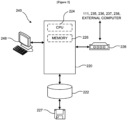
- the controller 240 may be embodied by a computer that includes a CPU (central processing unit) 224, a memory 226 such as a RAM (Random Access Memory) and a ROM (Read Only Memory) serving as a temporary memory device, a hard disk drive (HDD) 222 serving as a memory device, and a transmission/reception part 228 serving as a communication part.
- a CPU central processing unit
- memory 226 such as a RAM (Random Access Memory) and a ROM (Read Only Memory) serving as a temporary memory device
- HDD hard disk drive
- transmission/reception part 228 serving as a communication part.
- the controller 240 may further include a display such as a liquid crystal display and a user interface device 248 serving as an operation part including a keyboard and a pointing device such as a mouse.
- recipe files (not shown) containing recipes defining processing conditions and processing sequences
- a control program file (not shown) containing a control program for executing the recipes
- a parameter file (not shown) containing parameters for configuring the processing condition and the processing sequence
- a display file (not shown) defining an input screen for entering process parameters are stored in the hard disk drive 222.
- the transmission/reception part 228 of the controller 240 may be connected to a switching hub (not shown).
- the controller 240 may transmit and receive data to and from an external computer via a network using the transmission/reception part 228.
- the controller 240 is electrically connected to components such as a gas flow rate controller (hereinafter, also referred to as a "mass flow controller” or an “MFC”) 235, a pressure controller 236, an operation controller 237 and a temperature controller 238 and sensors (not shown) provided in the housing 111 via a communication line through the transmission/reception part 228.
- a gas flow rate controller hereinafter, also referred to as a "mass flow controller” or an "MFC”
- MFC mass flow controller
- the controller 240 may be embodied by a general computer system as well as a dedicated system.
- the controller 240 may be embodied by installing the control program (also referred to as a "program") in the general computer system from a recording medium 227 such as a USB memory which stores the program.
- the program is configured to execute predetermined processes of the recipes.
- the method of providing the program is not limited.
- the program may be provided through the recording medium as described above, a communication line, a communication network or a communication system.
- the program may be posted on a bulletin board on the communication network, and may be provided by being superimposed on a carrier wave via the communication network.
- the program provided as described above may be executed to perform the above-described process under an OS (operating system) just like any other application programs.
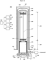
- the process furnace 202 includes a heater 206 serving as a heating apparatus (heating mechanism).
- the heater 206 is of a cylindrical shape, and is vertically installed while being supported by a support plate (also referred to as a "heater base") 251.
- An upper opening of the heater 206 is closed by a lid part 207.
- a soaking tube (also referred to as an "outer tube”) 205 is provided on an inner side of the heater 206 so as to be concentric with the heater 206.
- the soaking tube 205 is made of a heat resistant material such as silicon carbide (SiC), and is of a cylindrical shape with a closed upper end and an open lower end.
- a reaction tube (also referred to as an "inner tube”) 204 is provided on an inner side of the soaking tube 205 so as to be concentric with the soaking tube 205.
- the reaction tube 204 is made of a heat resistant material such as quartz (SiO 2 ), and is of a cylindrical shape with a closed upper end and an open lower end.
- a process chamber 201 is provided in a hollow cylindrical portion of the reaction tube 204.
- the process chamber 201 is configured to accommodate vertically arranged wafers including the wafer 200 in a horizontal orientation in a multistage manner by the boat 217 described later.
- a space between the reaction tube 204 and the soaking tube 205 is provided with a clearance of only about 30 mm. Therefore, a pipe with a large diameter cannot be provided in the space between the reaction tube 204 and the soaking tube 205.
- a gas introduction portion (hereinafter, also referred to as a "gas inlet”) 233 of a pipe shape is provided at a lower end side of the reaction tube 204.
- a process gas is supplied into the reaction tube 204 through the gas introduction portion 233 from an outside of the reaction tube 204.
- a plurality of thin pipes (also simply referred to as “thin pipes", for example, three thin pipes according to the first embodiment) 230 extend upward from the gas introduction portion 233 along an outer peripheral surface of the reaction tube 204.
- a diameter of each of the thin pipes 230 is smaller than a diameter of the gas introduction portion 233, and a cross-section of each of the thin pipes 230 is of a circular shape.
- the thin pipes 230 are connected to a preheating portion 260 serving as a preheating path arranged on the outer peripheral surface of the reaction tube 204.
- the thin pipes 230 may be considered as a part of the gas introduction portion 233.
- the thin pipes 230 are fixed to the inner tube 204 such that each of the thin pipes 230 contacts the inner tube 204 and the thin pipes 230 are adjacent to each other.
- By providing the thin pipes 230 it is possible to increase a flow rate of a gas such as the process gas supplied into the inner tube 204 at one time.
- the thin pipes 230 may be thin enough to fit in the space between the inner tube 204 and the outer tube 205.
- a cross-sectional shape of each of the thin pipes 230 is not limited to the circular shape.
- each of the thin pipes 230 may be of a rectangular shape.
- the diameter of each of the thin pipes 230 may range from 5 mm to 8 mm. It is preferable that the diameter of each of the thin pipes 230 is 5 mm.
- the number of the thin pipes 230 may be two or more, for example, three or more.
- the preheating portion 260 is connected to a plurality of thin pipes (also simply referred to as "thin pipes", for example, three thin pipes according to the first embodiment) 270. Similar to the thin pipes 230, the cross-section of each of the thin pipes 270 is of a circular shape. Configurations of the thin pipes 270 are essentially same as the thin pipes 230.
- the thin pipes 270 are connected to a nozzle pipe 274 via a buffer portion 272 provided at a ceiling of the reaction tube 204.
- the thin pipes 270 may also be referred to as a "first supplier” and the nozzle pipe 274 may also be referred to as a "second supplier”.
- the process gas introduced through the gas introduction portion 233 via a plurality of gas holes (also simply referred to as "gas holes") 278 is supplied to the process chamber 201.
- the gas holes 278 serve as a gas supplier, and are provided at the nozzle pipe 274 arranged on the outer peripheral surface of the reaction tube 204.
- the term "pipe member” refers to a assembly that communicates the gas introduction portion 233 to the gas holes 278. That is, components described above such as the thin pipes 230, the preheating portion 260, the thin pipes 270, the buffer portion 272, the nozzle pipe 274 and a thin pipe 276 described later may be collectively referred to as the "pipe member".
- the pipe member is not limited to the configuration of the first embodiment including the thin pipes 230, the preheating portion 260, the thin pipes 270, the buffer portion 272, the nozzle pipe 274 and the thin pipe 276.
- the pipe member is provided outside the reaction tube 204. That is, the pipe member is provided between the reaction tube 204 and the heater 206.
- the diameter of each of the thin pipes 230, the diameter of each of the thin pipes 270 and a diameter of thin pipe 276 are the same.
- a region of a side surface (hereinafter, also referred to as a "side wall") of the reaction tube 204 facing the plurality of the wafers including the wafer 200 to be processed by the gas in the reaction tube 204 may be referred to as a wafer processing region (also referred to as a "substrate processing region") 262, and a region below the wafer processing region 262 where the preheating portion 260 is disposed may be referred to as a gas preheating region 264.
- the preheating portion 260 is provided on the side surface of the reaction tube 204 at a position lower than the wafer processing region 262 where the plurality of the wafers including the wafer 200 are disposed in the process chamber 201.
- the preheating portion 260 extends in a direction detouring from a direction from the gas introduction portion 233 toward the ceiling of the reaction tube 204.
- the preheating portion 260 is configured to extend in a direction intersecting with the direction in which the process gas introduced through the gas introduction portion 233 flows to the ceiling of the reaction tube 204 at a shortest distance.
- at least a part of the preheating portion 260 is provided to extend in an outer peripheral direction of the reaction tube 204.
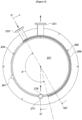
- the preheating portion 260 includes a plurality of preheating pipes (also simply referred to as "preheating pipes", for example, four preheating pipes according to the first embodiment) 266 extending in a circumferential direction of the reaction tube 204 over a range of approximately 190°.
- the preheating pipes 266 are arranged in a multistage manner in the vertical direction. End sides of the preheating pipes 266 adjacent to each other are alternately connected by a plurality of connecting pipes (also simply referred to as "connecting pipes”, for example, three connecting pipes according to the first embodiment) 268.
- a diameter of each of the connecting pipes 268 is smaller than a diameter of each of the preheating pipes 266, and a cross-section of each of the connecting pipes 268 is of a circular shape.
- the preheating portion 260 constitutes the preheating path of a rectangular waveform shape (two cycles, two reciprocations) as a whole.
- the connecting pipes 268 correspond to a first preheating portion
- the preheating pipes 266 correspond to a second preheating portion.
- the preheating portion 260 is configured by combining the connecting pipes 268 and the preheating pipes 266. A starting point and an ending point of the preheating path are located at the preheating pipes 266.
- the connecting pipes 268 is provided between a position of the preheating pipes 266 and another position of the preheating pipes 266.
- the angular range in which the preheating pipes 266 are located in the circumferential direction of the reaction tube 204 is determined as desired according to a positional relationship between the gas introduction portion 233 and the nozzle pipe 274.
- the angular range in which the preheating pipes 266 are located in the circumferential direction of the reaction tube 204 is determined by an angular range from an angular position of the gas introduction portion 233 to an angular position of the nozzle pipe 274 in the circumferential direction. For example, as shown in FIG.
- the angular range in which the preheating pipes 266 are located in the circumferential direction of the reaction tube 204 may be set to be greater than 0° and less than N°.
- the angular range in which the preheating pipes 266 are located in the circumferential direction of the reaction tube 204 may be set to be greater than 180° and less than N°.
- the angular range in which the preheating pipes 266 are located in the circumferential direction of the reaction tube 204 may be set to 190°.
- a configuration of each of the connecting pipes 268 is the same as that of each of the thin pipes 230 (or the thin pipes 270).
- cross-sectional areas of flow paths of the connecting pipes 268 are set to be essentially the same as cross-sectional areas of flow paths of the thin pipes (for example, three thin pipes) 230 or the thin pipes (for example, three thin pipes) 270.
- a temperature sensor 267 serving as a temperature detecting device is provided in a space (cylindrical space) between the reaction tube 204 and the soaking tube 205 (not shown in FIGS. 4C and 5 ).
- the temperature sensor 267 is provided on the space opposite to the preheating pipes 266 so as not to be in contact with or close to the preheating pipes 266. That is, when the preheating pipes 266 and the temperature sensor 267 are close to each other, the temperature sensor 267 intended to detect an inner temperature of the reaction tube 204 may detect a temperature of the preheating pipes 266 instead of the inner temperature of the reaction tube 204.
- the angular range in which the preheating pipes 266 are located in the circumferential direction of the reaction tube 204 is from the angular position of the gas introduction portion 233 to an angular position of the temperature sensor 267 in the circumferential direction of the reaction tube.
- a pipe whose vertical cross-section is of a rectangular shape may be used as each of the preheating pipes 266 according to the first embodiment.
- the shape of the pipe serving as each of the preheating pipes 266 to be same as a vertical cross-sectional shape of the space (also referred to as a "gap") between the reaction tube 204 and the soaking tube 205, it is possible to enlarge a cross-sectional shape (that is, a cross-sectional area) of the preheating path. As a result, it is possible to increase the flow rate of the gas such as the process gas passing through the preheating path.
- the preheating pipes 266 and the connecting pipes 268 constituting the preheating portion 260 are provided close to or in contact with the outer peripheral surface of the reaction tube 204, and are configured to transfer the heat from the heater 206 and the heat from the reaction tube 204 to the gas passing through the preheating path in the preheating pipes 266 and the connecting pipes 268.
- the cross-sectional shapes of the thin pipes 230 and the connecting pipes 268 are different from the cross-sectional shapes of the preheating pipes 266 in the gas preheating region 264.
- connecting parts between the thin pipes 230 and the preheating pipes 266 and connecting parts between the connecting pipes 268 and the preheating pipes 266 of the preheating portion 260 are configured to mix the gas passing through the preheating path.
- the gas introduced through the thin pipes 230 is supplied into the thin pipes 270 via the preheating portion 260 while a temperature of the gas at the connecting parts is uniformized.
- the effect of maintaining the temperature of the gas by mixing the gas at the connecting parts becomes remarkable.
- By reducing the length of each of the preheating pipes 266 in the vertical direction it is possible to increase the number of the connecting parts between the connecting pipes 268 and the preheating pipes 266.
- the preheating portion 260 is configured such that the cross-sectional areas of the flow paths of the thin pipes 230 or the cross-sectional area of the preheating path in the connecting pipes 268 are equal to or less than the cross-sectional area of the preheating path in the preheating pipes 266, and the gas may pass through the preheating path in the connecting pipes 268 and the preheating path in the preheating pipes 266 a plurality of times.
- the preheating portion 260 is configured such that the cross-sectional areas of the flow paths of the thin pipes 230 or the cross-sectional area of the preheating path in the connecting pipes 268 are equal to or less than the cross-sectional area of the preheating path in the preheating pipes 266, and the gas may pass through the preheating path in the connecting pipes 268 and the preheating path in the preheating pipes 266 a plurality of times.
- the preheating pipes 266 are fixed to the reaction tube 204 via a plurality of mounting portions (also simply referred to as “mounting portions") 266A.
- the mounting portions 266A are provided in the outer peripheral direction of the reaction tube 204.
- the inner temperature of the reaction tube 204 may decrease due to the gas flowing in the preheating pipes 266, (ii) the flow rate of the gas may decrease due to the welding deformation of the preheating pipes 266 and (iii) dimensional variations in the clearance and interferences with the components in the reaction tube 204 such as the boat 217 may occur due to the welding deformation of the reaction tube 204. Therefore, in order to address the risks described above, a structure shown in FIG. 4D may be used. According to the structure shown in FIG. 4D , it is possible to reduce welding portions (or welding areas) and contact areas with the reaction tube 204 as much as possible. Therefore, it is possible to reduce the risks caused by the welding areas and the contact areas.
- the upper ends of the thin pipes 230 extending from the gas introduction portion 233 are connected to the end of a lowermost preheating pipe among the preheating pipes 266 constituting the preheating portion 260, and the lower ends of the thin pipes 270 extending upward are connected to the end of a uppermost preheating pipe among the preheating pipes 266.
- the nozzle pipe 274 extending in the vertical direction is provided at the outer peripheral surface of the reaction tube 204 opposite to the thin pipes 230 and the thin pipes 270.
- the nozzle pipe 274 serves as a part of the side wall of the reaction tube 204, and a part of the nozzle pipe 274 is provided so as to protrude into the space between the reaction tube 204 and the soaking tube 205.
- An upper end of the nozzle pipe 274 is connected to the buffer potion 272 via the thin pipe 276 with a small diameter so that the gas passing through the buffer portion 272 is introduced into the nozzle pipe 274.
- the gas holes 278 shown in FIG. 5 configured to eject the gas into the reaction tube 204 are provided at the nozzle pipe 274 from a lower end to the upper end of the nozzle pipe 274 at a predetermined interval (a constant interval) along the longitudinal direction.
- the gas holes 278 are arranged between the plurality of the wafers including the wafer 200 at the same interval as the interval between the supporting portions of the boat 217 configured to support the plurality of the wafers.
- the gas holes 278 are provided at the nozzle pipe 274 so as to eject the gas between the plurality of the wafers including the wafer 200.
- a gas exhaust portion (also referred to as an "exhaust portion” or a “gas outlet”) 231 of a pipe shape is provided at the lower side of the reaction tube 204 opposite to the nozzle pipe 274.
- the gas exhaust portion 231 is configured to discharge (exhaust) an inner atmosphere of the reaction tube 204 to the outside of the reaction tube 204.
- the gas exhaust portion 231 is provided closer to the gas introduction portion 233 than to the nozzle pipe 274.
- the gas exhaust portion 231 is located at a position of the reaction tube 204 opposite to the other position where the nozzle pipe 274 is located.
- An angular position of the gas exhaust portion 231 is between the angular position of the gas introduction portion 233 and the angular position of the nozzle pipe 274.
- the gas exhaust portion 231 is provided lower than the preheating pipes 266.
- a process gas supply source (not shown), a carrier gas supply source (not shown) and an inert gas supply source (not shown) are connected to an upstream side of the gas introduction portion 233 via the MFC (that is, the gas flow rate controller) 235.
- the MFC 235 is configured to control the flow rate of the gas supplied into the process chamber 201 to a desired flow rate at a desired timing.
- a gas supply system according to the first embodiment is constituted by at least the process gas supply source, the carrier gas supply source, the inert gas supply source and the MFC 235.
- a sequencer (not shown) is configured to control the supply or the stop of the supply of the gas by opening and closing a valve (not shown).
- the controller 240 is configured to control the MFC 235 and the sequencer to adjust the flow rate of the gas supplied into the process chamber 201 to the desired flow rate at the desired timing.
- FIG. 6 schematically illustrates the process furnace 202 when the boat 217 is loaded into the reaction tube 204.
- FIG. 6 only some of the plurality of the wafers including the wafer 200 are shown for simplification.
- Horizontal arrows in FIG. 6 indicate flows (directions) of the process gas.
- a distance (pitch) between adjacent heat insulating plates among the heat insulating plates 218A is about ten millimeters, and the distances between the gas holes 278 of the nozzle pipe 274 (not shown in FIG. 6 ) are also set to be equal to the pitch of the heat insulating plates 218A.
- a lowermost gas hole among the gas holes 278 is provided at a position facing the gas exhaust portion 231 shown in FIG. 5 .
- the gas is continuously heated by the heat from the reaction tube 204 and the heat from the heater 206 while the gas temporarily stagnates in the buffer portion 272 described above. Then, the gas sufficiently heated by the heat is ejected through the gas holes 278 of the nozzle pipe 274 and supplied into the process chamber 201. As a result, it is possible to reduce temperature differences between the gas supplied into the process chamber 201 and components constituting the process chamber 201 such as a SiC component, a quartz component and the wafer 200. Therefore, it is possible to reduce the particles due to the temperature differences.
- a support body 257 serving as a base flange capable of hermetically sealing a lower end opening of the reaction tube 204 and the lid 219 are provided at a lower end of the reaction tube 204.
- the lid 219 is made of a metal such as stainless steel and is of a disk shape.
- the support body 257 provided on the lid 219 is made of quartz and is of a disk shape.
- An O-ring 223 serving as a sealing part in contact with the lower end of the reaction tube 204 is provided on an upper surface of the support body 257.
- a rotating mechanism 254 configured to rotate the boat 217 is provided on the lid 219 opposite to the process chamber 201.
- a rotating shaft 255 of the rotating mechanism 254 is connected to the heat insulating cylinder 218 and the boat 217 through the lid 219 and the support body 257.
- the rotating mechanism 254 rotates the heat insulating cylinder 218 and the boat 217 to rotate the plurality of the wafers including the wafer 200.
- the lid 219 is elevated or lowered in the vertical direction by the boat elevator 115 vertically installed outside the reaction tube 204 so as to load the boat 217 into or unload the boat 217 out of the process chamber 201.
- the operation controller 237 is electrically connected to the rotating mechanism 254 and the boat elevator 115.
- the operation controller 237 may control the rotating mechanism 254 and the boat elevator 115 such that the rotating mechanism 254 and the boat elevator 115 perform a desired operation at a desired timing.
- the boat 217 is made of a heat resistant material such as quartz and silicon carbide (SiC), and is configured to support the plurality of wafers including the wafer 200 vertically arranged in a horizontal orientation in a multistage manner with their centers aligned.
- the heat insulating cylinder 218 serving as a heat insulating member is provided below the boat 217 to support the boat 217.
- the heat insulating cylinder 218 is made of a heat resistant material such as quartz and silicon carbide and is of a cylindrical shape.
- the heat insulating cylinder 218 is configured to suppress the heat emitted from the heater 206 from being transmitted to the lower end portion of the reaction tube 204.
- the temperature controller 238 is electrically connected to the heater 206 and the temperature sensor 267.
- the temperature controller 238 is configured to adjust a state of electric conduction to the heater 206 based on the temperature detected by the temperature sensor 267 such that an inner temperature of the process chamber 201 reaches and is maintained at a desired temperature at a desired timing.
- the substrate processing may be performed using the process furnace 202 of the substrate processing apparatus 100.
- the operations of the components constituting the substrate processing apparatus 100 are controlled by the controller 240.
- the boat 217 charged with the plurality of wafers is elevated by the boat elevator 115 and transferred (loaded) into the process chamber 201 (boat loading).
- the lid 219 seals the lower end of the reaction tube 204 via the support body 257 and the O-ring 223.
- the process chamber 201 is heated by the heater 206 such that the inner temperature of the process chamber 201 reaches and is maintained at the desired temperature.
- the electric conduction state to the heater 206 is feedback-controlled based on the temperature detected by the temperature sensor 267 such that the inner temperature of the process chamber 201 has a predetermined temperature distribution.
- the rotating mechanism 254 rotates the heat insulating cylinder 218 and the boat 217 to rotate the plurality of wafers including the wafer 200.
- the gas supplied through the process gas supply source (not shown) and the carrier gas supply source (not shown) and adjusted (controlled) to the desired flow rate by the MFC 235 is introduced into the gas introduction portion 233.
- the gas introduced into the gas introduction portion 233 at the lower side of the reaction tube 204 flows through the thin pipes 230, and is introduced into the nozzle pipe 274 via the preheating portion 260, the thin pipes 270 and the buffer portion 272. Then, the gas is introduced into the process chamber 201 through the gas holes 278.
- the gas introduced into the gas introduction portion 233 is preheated at the preheating portion 260 by the heat from the heater 206 and the heat from the reaction tube 204, and passes through the thin pipes 270 in the wafer processing region 262 after the temperature of the gas is sufficiently increased. Therefore, it is possible to suppress the decrease in the temperature of the wafer processing region 262. As a result, it is possible to uniformize the temperature of the wafer processing region 262 facing the plurality of the wafers including the wafer 200 in the reaction tube 204.
- the gas with a low temperature may pass through the thin pipes 270, the temperature of a portion where the thin pipes 270 are arranged may decrease and the temperature of the reaction tube 204 may become uneven (nonuniform). As a result, a temperature uniformity of the plurality of the wafers including the wafer 200 may be adversely affected.
- the gas heated by passing through the preheating portion 260 is ejected into the process chamber 201 through the gas holes 278 provided in the nozzle pipe 274 via the buffer portion 272.
- the gas ejected through the gas holes 278 comes into contact with the surface of the wafer 200 when passing through the process chamber 201.
- the process such as the oxidation process and the diffusion process is performed onto the wafer 200.
- the wafer 200 is also rotated such that the gas contacts the entire surface of the wafer 200.
- the temperature of the wafer processing region 262 facing the plurality of wafers including the wafer 200 is uniformized, it is possible to uniformly heat the plurality of wafers including the wafer 200.
- the gas with a uniform flow rate is supplied through each of the gas holes 278 to the process chamber 201 at a predetermined flow rate.
- the flow rate of the gas is adjusted to a desired flow rate by the MFC 235, and the gas with the flow rate thereof adjusted is then supplied to a water vapor generator (not shown). Then, the gas containing the water vapor (H 2 O) generated by the water vapor generator is supplied into the process chamber 201.
- an inert gas is supplied through inert gas supply source to replace an inner atmosphere of the process chamber 201 with an inert gas, and the inner pressure of the process chamber 201 is returned to normal pressure.
- the lid 219 is lowered by the boat elevator 115 and the lower end of the reaction tube 204 is opened. Then, the processed wafers including the wafer 200 charged in the boat 217 are unloaded out of the reaction tube 204 through the lower end of the reaction tube 204 (boat unloading). The processed wafers 200 are then discharged from the boat 217 (wafer discharging).
- the gas passing through the thin pipes 270 provided at the wafer processing region 262 is sufficiently preheated at the preheating portion 260, and the influence of the temperature of the gas passing through the thin pipes 270 on the wafer processing region 262 is suppressed.
- the temperature of the wafer processing region 262 facing the plurality of wafers including the wafer 200 is uniformized, it is possible to suppress the processing failure of the wafer 200 due to the nonuniform temperature of the wafer processing region 262.
- a substrate processing apparatus 100 according to a second embodiment will be described with reference to FIG. 7 .
- the same components as those of the first embodiment will be denoted by like reference numerals, and detailed description thereof will be omitted.
- the substrate processing apparatus 100 it is possible to heat the gas stagnated in the buffer part 272 by at least one among the upper heater 280 and the ceiling heater 282. Therefore, it is possible to process the wafer 200 by supplying the gas with a higher temperature than that of the first embodiment into the process chamber 201 of the reaction tube 204. Accordingly, the gas such as the process gas can be supplied into the process chamber 201 while reducing a temperature difference between the process gas and components constituting the process chamber 201. As a result, it is possible to reduce the particles due to the temperature difference.
- Other operations and effects of the second embodiment are the same as those of the first embodiment.
- FIGS. 8A through 8C a substrate processing apparatus 100 according to a third embodiment will be described with reference to FIGS. 8A through 8C .
- the same components as those of the first embodiment will be denoted by like reference numerals, and detailed description thereof will be omitted.
- a plurality of joints (also simply referred to as "joints") 286 are configured to connect the preheating pipes 284 and the connecting pipes 268, the preheating pipes 284 and the thin pipes 230, and the preheating pipes 284 and the thin pipes 270, respectively.
- the preheating pipes 284 and the joints 286 correspond to a second preheating portion according to the third embodiment.
- a pipe whose vertical cross-section is of a rectangular shape is used as each of the connecting pipes 268 according to the third embodiment.
- a cross-sectional shape of each of the connecting pipes 268 of the third embodiment is different from those of the connecting pipes 268 of the first embodiment, the preheating pipes 284, the thin pipes 230 and the thin pipes 270, whose cross-sections are of a circular shape.
- a thin pipe is used as each of the preheating pipes 284.
- a set of three thin pipes are used as the preheating pipes 284. Therefore, it is possible to sufficiently preheat the gas similarly to the preheating pipes 266 of the first embodiment.
- Other operations and effects of the third embodiment are the same as those of the first and second embodiments.
- the test is performed using two types of reaction tubes according to comparative examples (that is, a first comparative example and a second comparative example) and three types of reaction tubes according to examples (that is, a first example, a second example and a third example) of the embodiments in which the preheating path described above is provided.
- Test results obtained by comparing and verifying the reaction tubes according to the first comparative example, the second comparative example, the first example, the second example and the third example will be described below.
- the same components as those of the embodiments described above will be denoted by like reference numerals, and detailed description thereof will be omitted.
- the nozzle pipe 274 and an internal structure of the reaction tube 204 according to each of the comparative examples and the examples are the same. However, according to each of the comparative examples and the examples, a configuration of a gas path from the gas introduction portion 233 to the nozzle pipe 274 is different. Hereinafter, differences between the gas paths according to the comparative examples and the examples will be described.
- a thin pipe 292 extending upward on the outer surface of the reaction tube 204 from the gas introduction portion 233 is directly connected to the nozzle pipe 274 across the uppermost side of the reaction tube 204.
- an inner diameter ⁇ of the thin pipe 292 is 21 mm.
- no preheating path is provided.
- the thin pipes (three thin pipes) 230 extend upward on the outer surface of the reaction tube 204 from the gas introduction portion 233 to the preheating portion 260.
- an inner diameter ⁇ of each of the three thin pipes 230 is 5 mm.
- the thin pipes (three thin pipes) 270 extending upward from the preheating portion 260 are connected to the nozzle pipe 274 across the uppermost side of the reaction tube 204.
- the preheating portion 260 is configured by disposing the three thin pipes 230 serving as preheating pipes in the circumferential direction of the reaction tube 204 over a range of 190° and reciprocating the preheating path once.
- the thin pipes (three thin pipes) 230 extend upward on the outer surface of the reaction tube 204 from the gas introduction portion 233 to the preheating portion 260.
- the inner diameter ⁇ of each of the three thin pipes 230 is 5 mm.
- the thin pipes (three thin pipes) 270 extending upward from the preheating portion 260 are connected to the nozzle pipe 274 across the uppermost side of the reaction tube 204.
- the preheating portion 260 is configured by disposing the three thin pipes 230 serving as the preheating pipes in the circumferential direction of the reaction tube 204 over a range of 190° and reciprocating the preheating path twice.
- the thin pipes (three thin pipes) 230 extend upward on the outer surface of the reaction tube 204 from the gas introduction portion 233 to the preheating portion 260.
- the inner diameter ⁇ of each of the three thin pipes 230 is 5 mm.
- the thin pipes (three thin pipes) 270 extending upward from the preheating portion 260 are connected to the nozzle pipe 274 across the uppermost side of the reaction tube 204.
- the preheating portion 260 is configured by disposing a rectangular pipe 294 in the circumferential direction of the reaction tube 204 over a range of 190° and reciprocating the preheating path twice.
- a cross-section of the rectangular pipe 294 is of a rectangular shape with dimensions of 24 ⁇ 3 mm.
- FIG. 11 schematically illustrates the test results in which temperatures of inner walls of the reaction tubes (that is, temperature distributions) according to the first comparative example, the second comparative example, the first example, the second example and the third example are represented as differences in concentration.
- temperature at position of the reaction tube 204 where the thin pipes 290 extending upward from the gas introduction portion 233 or the thin pipe 292 extending upward is provided are lower than temperature at position of the reaction tube 204 where the thin pipes 290 or the thin pipe 292 is not provided.
- the temperature of the reaction tube 204 is uneven (nonuniform).
- the first example, the second example and the third example it is possible to suppress the unevenness (nonuniformity) in the temperature of the reaction tube 204 as compared with the first comparative example and the second comparative example.
- the preheating path of the preheating portion 260 of each of the examples is longer than that of each of the comparative examples (that is, the first comparative example and the second comparative example). Therefore, according to the examples, the gas is preheated more efficiently and the influence of the gas passing through the thin pipes 270 is reduced. Therefore, according to the examples, it is possible to suppress the unevenness (nonuniformity) in the temperature of the reaction tube 204 as compared with the comparative examples.
- the preheating path of the preheating portion 260 of each of the second example and the third example is longer than that of the first example.
- the gas is preheated more efficiently and the influence of the gas passing through the thin pipes 270 is more reduced. Therefore, according to the second example and the third example, it is possible to suppress the unevenness (nonuniformity) in the temperature of the reaction tube 204 as compared with the first example.
- the cross-sectional area (or dimensions) of the preheating path of the preheating portion 260 of the third example is greater than that the cross-sectional area (or inner diameter) of the preheating path of the preheating portion 260 of the second example. Therefore, according to the third example, the gas is preheated more efficiently and the influence of the gas passing through the thin pipes 270 is more reduced.
- the third example it is possible to suppress the unevenness (nonuniformity) in the temperature of the reaction tube 204 as compared with the second example.
- the cross-sectional area (or dimensions) of the preheating path of the preheating portion 260 is large and the preheating path is long, an area where the gas is applied to the heat in the pre-heating portion 260 and a contact time during the gas being applied to the heat in the pre-heating portion 260 are increased as compared with the comparative examples, the first example and the second example. Therefore, the temperature of the gas is sufficiently increased before flowing into the thin pipes 270. As a result, it is possible to substantially eliminate the temperature unevenness (nonuniformity) in the wafer processing region 262.
- a graph on a left side of FIG. 12 schematically illustrates the temperatures (temperature distributions) of the inner walls of the reaction tubes according to the comparative examples and the examples at a side (indicated by "INLET SIDE") in the vertical direction where the gas introduction portion 233 is provided.
- a graph on a center side of FIG. 12 schematically illustrates the temperatures (temperature distributions) of the inner walls of the reaction tubes according to the comparative examples and the examples at a side (indicated by "OUTLET SIDE") in the vertical direction where the gas exhaust portion 231 is provided.
- the vertical axis of a graph on a right side of FIG. 12 represents the height dimension (in unit of mm) with the lower end of the wafer processing region 262 as the reference ("0")
- the horizontal axis of the graph on the right side of FIG. 12 represents the temperature difference between the temperature of the "INLET SIDE” and the temperature of the "OUTLET SIDE". As shown in the graph on the right side of FIG.
- the temperature difference in the wafer processing region 262 according to each of the examples is small as compared with that of each of the comparative examples. That is, the temperature unevenness (nonuniformity) in the wafer processing region 262 according to each of the examples is small as compared with that of each of the comparative examples.
- the buffer portion 272 is provided at the uppermost side of the reaction tube 204 in addition to the preheating portion 260, and the gas temporarily stagnated in the buffer portion 272 is heated.
- the buffer portion 272 may be omitted, and ends of the thin pipes 270 may be directly connected to the nozzle pipe 274.
- the pipe member may include the thin pipes 230, the preheating portion 260, the thin pipes 270 and the nozzle pipe 274.
- a substrate processing apparatus including: the reaction tube 204 provided therein with the process chamber 201 where the wafer 200 is processed; the gas introduction portion 233 provided at the lower end of the reaction tube 204 and through which the process gas is introduced into the reaction tube 204; the pipe member provided between the reaction tube 204 and the heater 206, extending in the direction from the gas introduction portion 233 to the nozzle pipe 274 across the ceiling of the reaction tube 204, and configured to communicate the gas introduction portion 233 with the nozzle pipe 274; and the gas exhaust portion 231 configure to exhaust the process gas from the process chamber 201.
- the nozzle pipe 274 is provided on the side surface of the reaction tube 204, and the gas holes 278 are provided at the nozzle pipe 274.
- the gas exhaust portion 231 is provided at the lower end of the reaction tube 204 opposite to the nozzle pipe 274.
- the pipe member includes the preheating path (that is, the preheating portion 260).
- the preheating portion 260 is provided on the side surface of the reaction tube 204 at the position lower than the substrate processing region where the plurality of the wafers including the wafer 200 are disposed in the process chamber 201, and extends in a direction intersecting with a direction of a shortest distance connecting the gas introduction portion 233 and the ceiling of the reaction tube 204.
- Operations and effects of another embodiment described above are the same as at least those of the first embodiment.
- at least one among the upper heater 280 and the ceiling heater 282 of the second embodiment may be further provided. In such a case, the operations and the effects of another embodiment described above are the same as those of the second embodiment.
- the temperature of the gas ejected through the nozzle pipe 274 into the process chamber 201 is sufficiently high (that is, the temperature required for processing the wafer 200 is reached).
- the temperature of the gas ejected into the process chamber 201 may be sufficiently increased and the temperature of the gas in the flow path up to the gas holes 278 may be sufficiently increased. Therefore, in such a case, as shown in FIG.
- the buffer portion 272 and the nozzle pipe 274 may be omitted, and a simple configuration in which the thin pipes 230, the thin pipes 270 and the preheating portion 260 are provided on the outer peripheral surface of the reaction tube 204 and the gas holes 278 are provided at the thin pipes 270 at the ceiling of the reaction tube 204 may be used.
- the pipe member may include the thin pipes 230, the preheating portion 260 and the thin pipes 270.
- a substrate processing apparatus including: the reaction tube 204 provided therein with the process chamber 201 where the wafer 200 is processed; the gas introduction portion 233 provided at the lower end of the reaction tube 204 and through which the process gas is introduced into the reaction tube 204; the pipe member provided between the reaction tube 204 and the heater 206 and configured to communicate the gas introduction portion 233 with the gas holes 278; and the gas exhaust portion 231 configure to exhaust the process gas from the process chamber 201.
- the gas holes 278 are provided at the ceiling of the reaction tube 204, and are configured to supply the process gas into the process chamber 201.
- the pipe member includes the preheating path (that is, the preheating portion 260).
- the preheating portion 260 is provided on the side surface of the reaction tube 204 at the position lower than the substrate processing region where the plurality of the wafers including the wafer 200 are disposed in the process chamber 201, and extends in a direction intersecting with a direction of connecting the gas introduction portion 233 and the ceiling of the reaction tube 204 by the shortest distance. Operations and effects of still another embodiment described above are the same as those of the first embodiment.
- the buffer portion 272 provided at the ceiling of the reaction tube 204 to temporarily store the process gas may be further provided.
- the buffer portion 272 is configured to communicate the pipe member to the process chamber 201, and the gas holes 278 configured to supply the process gas into the process chamber 201 are provided at the buffer portion 272.
- the process gas is heated by the heater 206. Therefore, it is possible to heat the process gas sufficiently.
- at least one among the upper heater 280 and the ceiling heater 282 of the second embodiment may be further provided. In such a case, the operations and the effects of still another embodiment described above are the same as those of the second embodiment.
- the above-described embodiments are described by way of an example in which the flow path of the gas (that is, the preheating path constituted by components such as the preheating pipes 266 and the connecting pipes 268) is of the rectangular waveform shape when viewed from the reaction tube 204.
- the above-described technique is not limited thereto.
- the preheating path instead of the rectangular waveform shape, may be of a so-called zigzag shape such as a sine curve shape and a triangular wave shape. In such a case, a specific shape of the zigzag shape and a direction in which the zigzag shape extends are not particularly limited.
- the preheating portion 260 may be constituted by: a first portion on the side surface of the reaction tube 204 extending in the direction (for example, the circumferential direction of the reaction tube 204) intersecting with the direction (for example, the vertical direction with respect to the reaction tube 204) of connecting the gas introduction portion 233 and the buffer portion 272 by the shortest distance in the flow path of the gas; and a second portion such as pipes bypassing in the circumferential direction rather than connecting the gas introduction portion 233 to the buffer portion 272 with the shortest distance so as to lengthen the preheating path.
- a first portion on the side surface of the reaction tube 204 extending in the direction (for example, the circumferential direction of the reaction tube 204) intersecting with the direction (for example, the vertical direction with respect to the reaction tube 204) of connecting the gas introduction portion 233 and the buffer portion 272 by the shortest distance in the flow path of the gas
- a second portion such as pipes bypassing in the circumferential direction rather than connecting the gas introduction portion 233 to the buffer portion 27
- the preheating path (that is, the pipes) through which the gas passes may be provided in a spiral shape on the outer peripheral surface of the reaction tube 204. In such a case, it is possible to lengthen the preheating path through which the gas flows. Thereby, it is possible to sufficiently preheat the gas.
- the above-described embodiments are described by way of an example in which the wafer serving as a substrate is processed.
- the above-described technique is not limited thereto.
- the above-described technique may also be applied to substrate processing apparatuses configured to process a glass substrate of a liquid crystal panel or a substrate such as a magnetic disk and an optical disk.
- a reaction tube having a process chamber; a gas introduction portion provided at a lower end; a first supplier provided along a side surface to face a substrate processing region; and a preheating portion provided lower than the substrate processing region, the preheating portion including: a first preheating portion extending in a direction from the gas introduction portion toward a ceiling; and a second preheating portion extending in a direction perpendicular to the above direction, wherein the preheating portion connects the gas introduction portion with the first supplier by combining the first preheating portion and the second preheating portion.
- substrate processing apparatus processing apparatus
- process chamber 200: wafer (substrate)
- reaction tube inner tube
- process furnace 217 boat (substrate retainer)
- heater heating apparatus
- gas introduction portion gas inlet
- 260:preheating portion pipe member, preheating path
- 262 wafer processing region (substrate processing region)
- 266:preheating pipes second preheating portion, pipe member, preheating path
- 268 connecting pipes (first preheating portion, pipe member, preheating path)
- 270:thin pipes first supplier, pipe member)
- second supplier , pipe member
- pipe member nozzle pipe
- gas holes gas supplier 284: preheating pipes (third preheating portion , pipe member, preheating path)
Landscapes
- Chemical & Material Sciences (AREA)
- Engineering & Computer Science (AREA)
- Mechanical Engineering (AREA)
- Materials Engineering (AREA)
- General Chemical & Material Sciences (AREA)
- Chemical Kinetics & Catalysis (AREA)
- Metallurgy (AREA)
- Organic Chemistry (AREA)
- General Engineering & Computer Science (AREA)
- Physics & Mathematics (AREA)
- Plasma & Fusion (AREA)
- Analytical Chemistry (AREA)
- Crystallography & Structural Chemistry (AREA)
Claims (19)
- Eine Reaktionsröhre (204), die darin mit einer Verarbeitungskammer (201) versehen ist und von einer darum vorgesehenen Heizeinrichtung erhitzt wird, wobei die Reaktionsröhre (204) folgendes aufweist:einen Gaseinführteil (233), der an einer unteren Seite vorgesehen ist, und durch welchen ein Verarbeitungsgas eingeführt wird;eine erste Zufuhreinrichtung (270), die entlang einer Seitenoberfläche vorgesehen ist, und zwar wenigstens an einer Position, die einem Substratverarbeitungsbereich (262) zugewandt ist, wo eine Vielzahl von Substraten (200) verarbeitet wird; undeinen Vorheizteil (260), der an einer niedrigeren Position als der Substratverarbeitungsbereichs (262) vorgesehen ist, wobei der Vorheizteil (260) folgendes aufweist:einen ersten Vorheizteil (268), der sich in einer Richtung von dem Gaseinführteil (233) zu einer Decke hin erstreckt, undeinen zweiten Vorheizteil (266), der sich in einer Richtung senkrecht zu der Richtung von dem Gaseinführteil (233) zu der Decke hin erstreckt,wobei der Vorheizteil (260) konfiguriert ist, um den Gaseinführteil (233) mit der ersten Zufuhreinrichtung (270) zu verbinden, und zwar durch Kombinieren des ersten Vorheizteils (268) und des zweiten Vorheizteils (266),und wobei eine Querschnittsform des ersten Vorheizteils (268) verschieden zu derjenigen des zweiten Vorheizteils (266) ist.
- Die Reaktionsröhre (204) nach Anspruch 1, wobei ein Vorheizpfad durch Kombinieren des ersten Vorheizteils (268) und des zweiten Vorheizteils (266) in einer abwechselnden Weise gebildet wird.
- Die Reaktionsröhre (204) nach Anspruch 2, wobei eine Form des Vorheizpfads wenigstens eine Form aufweist, die aus der Gruppe ausgewählt ist, die aus einer Rechteckswellenform, einer Sinuswellenform und einer Dreieckswellenform besteht.
- Die Reaktionsröhre (204) nach Anspruch 2 und/oder 3, wobei ein Startpunkt und ein Endpunkt des Vorheizpfads an dem zweiten Vorheizteil (266) angeordnet sind.
- Die Reaktionsröhre (204) nach einem oder mehreren der Ansprüche 1 bis 4, wobei der erste Vorheizteil (268) zwischen einer Position des zweiten Vorheizteils (266) und einer weiteren Position des zweiten Vorheizteils (266) vorgesehen ist.
- Die Reaktionsröhre (204) nach einem oder mehreren der Ansprüche 1 bis 5, wobei eine Querschnittsfläche eines Strömungspfads des ersten Vorheizteils (268) im Wesentlichen dieselbe wie diejenige eines Strömungspfads des zweiten Vorheizteils (266) ist.
- Die Reaktionsröhre (204) nach einem oder mehreren der Ansprüche 1 bis 5, wobei eine Querschnittsfläche eines Strömungspfads des zweiten Vorheizteils (266) größer als diejenige eines Strömungspfads des ersten Vorheizteils (268) ist.
- Die Reaktionsröhre (204) nach einem oder mehreren der Ansprüche 1 bis 7, wobei der zweite Vorheizteil (266) folgendes aufweist: einen Hauptvorheizteil (284), der konfiguriert ist, um das Verarbeitungsgas vorzuheizen; und eine Verbindung, die konfiguriert ist, um das erste Vorheizteil (268) und das Hauptvorheizteil (284) zu verbinden,
wobei eine Querschnittsform des ersten Vorheizteils (268) verschieden zu derjenigen der Verbindung ist, und eine Querschnittsform von dem ersten Vorheizteil (268) dieselbe wie diejenige des Hauptvorheizteils (284) ist. - Die Reaktionsröhre (204) nach einem oder mehreren der Ansprüche 1 bis 8, wobei der erste Vorheizteil (268) dieselbe Konfiguration wie diejenige der ersten Zufuhreinrichtung (270) aufweist.
- Die Reaktionsröhre (204) nach einem oder mehreren der Ansprüche 1 bis 9, wobei jedes von dem ersten Vorheizteil (268) und der ersten Zufuhreinrichtung (270) aus einer Vielzahl von Rohren gebildet ist, und
eine Anzahl der Rohre, welche den ersten Vorheizteil (268) bilden, ist dieselbe wie die Anzahl der Rohre, welche die erste Zufuhreinrichtung (270) bilden. - Die Reaktionsröhre (204) nach einem oder mehreren der Ansprüche 1 bis 10, die ferner eine Vielzahl von Befestigungsteilen (266A) aufweist, und
der zweite Vorheizteil (266) an der Seitenoberfläche mit der Vielzahl von dazwischen eingefügten Befestigungsteilen (266A) vorgesehen ist. - Die Reaktionsröhre (204) nach einem oder mehreren der Ansprüche 1 bis 11, die ferner eine zweite Zufuhreinrichtung (274) aufweist, die an der Seitenoberfläche gegenüber zu dem Gaseinführteil (233) vorgesehen ist, wobei eine Gaszufuhreinrichtung, die konfiguriert ist, um das Verarbeitungsgas in die Verarbeitungskammer (201) zuzuführen, an der zweiten Zufuhreinrichtung (274) vorgesehen ist,
wobei der zweite Vorheizteil (266) sich entlang einer Umfangsrichtung der Reaktionsröhre (204) innerhalb eines Winkelbereichs erstreckt, der gemäß einer Positionsbeziehung zwischen dem Gaseinführteil (233) und der zweiten Zufuhreinrichtung (274) bestimmt ist. - Die Reaktionsröhre (204) nach Anspruch 12, die ferner einen Gasauslassteil (231) aufweist, der konfiguriert ist, um das Verarbeitungsgas von der Verarbeitungskammer (201) auszulassen,
wobei der zweite Vorheizteil (266) sich innerhalb eines ersten Winkelbereichs von einer Winkelposition des Gaseinführteils (233) zu einer Winkelposition der zweiten Zufuhreinrichtung (274) erstreckt, wobei die Winkelposition des Gasauslassteils (231) in dem ersten Winkelbereich enthalten ist. - Die Reaktionsröhre (204) nach Anspruch 12 und/oder 13, wobei, wenn die Winkelposition des Gaseinführteils (233) als 0° definiert ist und die Winkelposition der zweiten Zufuhreinrichtung (274) als N° definiert ist (N ist eine positive Zahl kleiner als 360), der zweite Vorheizteil (266) sich innerhalb eines Winkelbereichs zwischen 0° und N° erstreckt.
- Die Reaktionsröhre (204) nach Anspruch 12 und/oder 13, wobei, wenn die Winkelposition des Gaseinführteils (233) als 0° definiert ist und die Winkelposition der zweiten Zufuhreinrichtung (274) als N° definiert ist (N ist eine positive Zahl kleiner als 360), der zweite Vorheizteil (266) sich innerhalb eines Winkelbereichs zwischen 180° und N° erstreckt.
- Die Reaktionsröhre (204) nach einem oder mehreren der Ansprüche 12 bis 15, die ferner einen Temperatursensor (267), der außerhalb der Reaktionsröhre (204) vorgesehen ist und konfiguriert ist, um eine Temperatur der Verarbeitungskammer (201) zu detektieren,
wobei der Temperatursensor (267) innerhalb eines zweiten Winkelbereichs von einer Winkelposition des Gaseinführteils (233) zu einer Winkelposition der zweiten Zufuhreinrichtung (274) angeordnet ist, wobei die Winkelposition des Gasauslassteils (231) von dem zweiten Winkelbereich ausgeschlossen ist. - Die Reaktionsröhre (204) nach Anspruch 16, wobei der zweite Vorheizteil (266) sich innerhalb eines Winkelbereichs von der Winkelposition des Gaseinführteils (233) bis zu der Winkelposition des Temperatursensors (267) erstreckt, und zwar ausschließlich der Winkelposition des Gasauslassteils (231).
- Eine Substratverarbeitungsvorrichtung (100), die folgendes aufweist:eine Reaktionsröhre (204), die darin mit einer Verarbeitungskammer (201) versehen ist und von einer darum vorgesehenen Heizeinrichtung erhitzt wird;einen Gaseinführteil (233), der an einem unteren Ende der Reaktionsröhre (204) vorgesehen ist, und durch welchen ein Verarbeitungsgas eingeführt wird;eine erste Zufuhreinrichtung (270), die entlang einer Seitenoberfläche der Reaktionsröhre (204) vorgesehen ist, und zwar wenigstens an einer Position, die einem Substratverarbeitungsbereich (262) zugewandt ist, wo eine Vielzahl von Substraten verarbeitet werden; undein Vorheizteil (260), der an einer niedrigeren Position als der Substratverarbeitungsbereich (262) vorgesehen ist, wobei der Vorheizteil (260) folgendes aufweist:einen ersten Vorheizteil (268), der sich in einer Richtung von dem Gaseinführteil (233) zu einer Decke der Reaktionsröhre (204) hin erstreckt; undeinen zweiten Vorheizteil (266), der sich in einer Richtung senkrecht zu der Richtung von dem Gaseinführteil (233) zu der Decke der Reaktionsröhre (204) hin erstreckt,wobei der Vorheizteil (260) konfiguriert ist, um den Gaseinführteil (233) mit der ersten Zufuhreinrichtung (270) zu verbinden, und zwar durch Kombinieren des ersten Vorheizteils (268) und des zweiten Vorheizteils (266); undeine Steuereinrichtung (240), die konfiguriert ist, um die Vielzahl der Substrate (200) durch Zuführung des Verarbeitungsgases auf die Vielzahl der Substrate (200) über den Vorheizteil zu verarbeiten,und wobei eine Querschnittsform des ersten Vorheizteils (268) verschieden zu derjenigen des zweiten Vorheizteils (266) ist.
- Ein Verfahren zur Herstellung einer Halbleitereinrichtung, das folgendes aufweist:(a) Laden einer Vielzahl von Substrates (200) in eine Reaktionsröhre (204) einer Substratverarbeitungsvorrichtung (100), wobei die Substratverarbeitungsvorrichtung (100) folgendes aufweist:eine Reaktionsröhre (204), die darin mit einer Verarbeitungskammer (201) versehen ist, und von einer darum vorgesehenen Heizeinrichtung erhitzt wird;einen Gaseinführteil (233), der an einem unteren Ende der Reaktionsröhre (204) vorgesehen ist, und durch welchen ein Verarbeitungsgas eingeführt wird;eine erste Zufuhreinrichtung (270), die entlang einer Seitenoberfläche der Reaktionsröhre (204) vorgesehen ist, und zwar wenigstens an einer Position, die einem Substratverarbeitungsbereich (262) zugewandt ist, wo eine Vielzahl von Substraten (200) verarbeitet werden; undein Vorheizteil (260), der an einer niedrigeren Position als der Substratverarbeitungsbereich (262) vorgesehen ist, wobei der Vorheizteil (260) folgendes aufweist:einen ersten Vorheizteil (268), der sich in einer Richtung von dem Gaseinführteil (233) zu einer Decke der Reaktionsröhre (204) hin erstreckt; undeinen zweiten Vorheizteil (266), der sich in einer Richtung senkrecht zu der Richtung von dem Gaseinführteil (233) zu der Decke der Reaktionsröhre (204) hin erstreckt,wobei der Vorheizteil (260) konfiguriert ist, um den Gaseinführteil (233) mit der ersten Zufuhreinrichtung (270) zu verbinden, und zwar durch Kombinieren des ersten Vorheizteils (268) und des zweiten Vorheizteils (266),wobei eine Querschnittsform des ersten Vorheizteils (268) verschieden zu derjenigen des zweiten Vorheizteils (266) ist; und(b) Verarbeiten der Vielzahl von Substraten (200) durch Zuführen des Verarbeitungsgases auf die Vielzahl der Substrate (200) durch den Vorheizteil (260).
Applications Claiming Priority (2)
| Application Number | Priority Date | Filing Date | Title |
|---|---|---|---|
| JP2019059430 | 2019-03-26 | ||
| JP2020027459A JP6994524B2 (ja) | 2019-03-26 | 2020-02-20 | 基板処理装置、反応管及び半導体装置の製造方法 |
Publications (2)
| Publication Number | Publication Date |
|---|---|
| EP3715501A1 EP3715501A1 (de) | 2020-09-30 |
| EP3715501B1 true EP3715501B1 (de) | 2024-11-27 |
Family
ID=69960474
Family Applications (1)
| Application Number | Title | Priority Date | Filing Date |
|---|---|---|---|
| EP20165340.9A Active EP3715501B1 (de) | 2019-03-26 | 2020-03-24 | Reaktionsrohr, substratverarbeitungsvorrichtung und verfahren zur herstellung eines halbleiterbauelements |
Country Status (4)
| Country | Link |
|---|---|
| US (1) | US20200312631A1 (de) |
| EP (1) | EP3715501B1 (de) |
| KR (1) | KR102377168B1 (de) |
| CN (1) | CN111755359B (de) |
Families Citing this family (2)
| Publication number | Priority date | Publication date | Assignee | Title |
|---|---|---|---|---|
| US11915960B2 (en) * | 2019-07-31 | 2024-02-27 | Asm Ip Holding B.V. | Vertical batch furnace assembly |
| CN116219411B (zh) * | 2023-05-05 | 2023-07-28 | 东领科技装备有限公司 | 一种用于成膜装置的气体喷射装置 |
Family Cites Families (11)
| Publication number | Priority date | Publication date | Assignee | Title |
|---|---|---|---|---|
| JPH0758696B2 (ja) * | 1984-11-09 | 1995-06-21 | 株式会社日立製作所 | 半導体ウエハ加熱装置 |
| US5458685A (en) * | 1992-08-12 | 1995-10-17 | Tokyo Electron Kabushiki Kaisha | Vertical heat treatment apparatus |
| JPH09326397A (ja) * | 1996-06-04 | 1997-12-16 | Dainippon Screen Mfg Co Ltd | ガスの加熱方法および装置 |
| JPH1167750A (ja) | 1997-08-22 | 1999-03-09 | Kokusai Electric Co Ltd | 外部燃焼装置、外部燃焼方法、外部燃焼装置を備える処理装置および外部燃焼装置を用いた処理方法 |
| US5948300A (en) * | 1997-09-12 | 1999-09-07 | Kokusai Bti Corporation | Process tube with in-situ gas preheating |
| JP4815352B2 (ja) * | 2004-09-16 | 2011-11-16 | 株式会社日立国際電気 | 熱処理装置、基板の製造方法、基板処理方法、及び半導体装置の製造方法 |
| KR20060027178A (ko) * | 2004-09-22 | 2006-03-27 | 삼성전자주식회사 | 반도체 확산로 장치 |
| JP4929199B2 (ja) * | 2008-02-01 | 2012-05-09 | 株式会社日立国際電気 | 基板処理装置および半導体装置の製造方法 |
| JP2012248675A (ja) | 2011-05-27 | 2012-12-13 | Hitachi Kokusai Electric Inc | ガス予備加熱筒、基板処理装置および基板処理方法 |
| JP6175432B2 (ja) * | 2012-05-28 | 2017-08-02 | 株式会社日立国際電気 | 基板処理装置、温度計測システム、処理装置の温度計測方法、搬送装置及び記録媒体 |
| JP6823575B2 (ja) * | 2016-11-18 | 2021-02-03 | 株式会社Kokusai Electric | 基板処理装置、反応管及び半導体装置の製造方法 |
-
2020
- 2020-03-19 CN CN202010204660.7A patent/CN111755359B/zh active Active
- 2020-03-20 KR KR1020200034308A patent/KR102377168B1/ko active Active
- 2020-03-24 EP EP20165340.9A patent/EP3715501B1/de active Active
- 2020-03-26 US US16/831,434 patent/US20200312631A1/en not_active Abandoned
Also Published As
| Publication number | Publication date |
|---|---|
| KR20200115210A (ko) | 2020-10-07 |
| US20200312631A1 (en) | 2020-10-01 |
| CN111755359A (zh) | 2020-10-09 |
| EP3715501A1 (de) | 2020-09-30 |
| CN111755359B (zh) | 2024-04-12 |
| KR102377168B1 (ko) | 2022-03-21 |
Similar Documents
| Publication | Publication Date | Title |
|---|---|---|
| US11359283B2 (en) | Reaction tube structure and substrate processing apparatus | |
| US10453735B2 (en) | Substrate processing apparatus, reaction tube, semiconductor device manufacturing method, and recording medium | |
| US11495477B2 (en) | Substrate processing apparatus | |
| JP5188326B2 (ja) | 半導体装置の製造方法、基板処理方法、及び基板処理装置 | |
| US20210043485A1 (en) | Substrate processing apparatus and substrate holder | |
| US20250327176A1 (en) | Processing apparatus and exhaust system | |
| US12467689B2 (en) | Furnace opening structure, substrate processing apparatus and method of manufacturing semiconductor device | |
| US12344935B2 (en) | Substrate processing apparatus, heat insulator assembly and method of manufacturing semiconductor device | |
| EP3715501B1 (de) | Reaktionsrohr, substratverarbeitungsvorrichtung und verfahren zur herstellung eines halbleiterbauelements | |
| KR102206194B1 (ko) | 기판 처리 장치 및 반도체 장치의 제조 방법 | |
| TWI775142B (zh) | 基板處理裝置,半導體裝置的製造方法及程式 | |
| JP6994524B2 (ja) | 基板処理装置、反応管及び半導体装置の製造方法 | |
| JP6823575B2 (ja) | 基板処理装置、反応管及び半導体装置の製造方法 | |
| US20230116953A1 (en) | Substrate retainer, substrate processing apparatus and method of manufacturing semiconductor device | |
| JP2019062191A (ja) | 基板処理装置及び半導体装置の製造方法 | |
| US20210134683A1 (en) | Method of Manufacturing Semiconductor Device, Non-transitory Computer-readable Recording Medium and Substrate Processing Apparatus | |
| JP5006821B2 (ja) | 基板処理装置および半導体装置の製造方法 | |
| JP2004079845A (ja) | 基板処理装置 |
Legal Events
| Date | Code | Title | Description |
|---|---|---|---|
| PUAI | Public reference made under article 153(3) epc to a published international application that has entered the european phase |
Free format text: ORIGINAL CODE: 0009012 |
|
| STAA | Information on the status of an ep patent application or granted ep patent |
Free format text: STATUS: THE APPLICATION HAS BEEN PUBLISHED |
|
| AK | Designated contracting states |
Kind code of ref document: A1 Designated state(s): AL AT BE BG CH CY CZ DE DK EE ES FI FR GB GR HR HU IE IS IT LI LT LU LV MC MK MT NL NO PL PT RO RS SE SI SK SM TR |
|
| AX | Request for extension of the european patent |
Extension state: BA ME |
|
| STAA | Information on the status of an ep patent application or granted ep patent |
Free format text: STATUS: REQUEST FOR EXAMINATION WAS MADE |
|
| 17P | Request for examination filed |
Effective date: 20210329 |
|
| RBV | Designated contracting states (corrected) |
Designated state(s): AL AT BE BG CH CY CZ DE DK EE ES FI FR GB GR HR HU IE IS IT LI LT LU LV MC MK MT NL NO PL PT RO RS SE SI SK SM TR |
|
| P01 | Opt-out of the competence of the unified patent court (upc) registered |
Effective date: 20230721 |
|
| RIC1 | Information provided on ipc code assigned before grant |
Ipc: H01L 21/677 20060101ALI20231218BHEP Ipc: H01L 21/673 20060101ALI20231218BHEP Ipc: H01L 21/67 20060101ALI20231218BHEP Ipc: C30B 25/14 20060101ALI20231218BHEP Ipc: C23C 16/455 20060101AFI20231218BHEP |
|
| RIN1 | Information on inventor provided before grant (corrected) |
Inventor name: NAKAMURA, IWAO Inventor name: HIRANO, ATSUSHI Inventor name: MURATA, SATORU Inventor name: MARUBAYASHI, TETSUYA |
|
| GRAP | Despatch of communication of intention to grant a patent |
Free format text: ORIGINAL CODE: EPIDOSNIGR1 |
|
| STAA | Information on the status of an ep patent application or granted ep patent |
Free format text: STATUS: GRANT OF PATENT IS INTENDED |
|
| INTG | Intention to grant announced |
Effective date: 20240619 |
|
| GRAS | Grant fee paid |
Free format text: ORIGINAL CODE: EPIDOSNIGR3 |
|
| GRAA | (expected) grant |
Free format text: ORIGINAL CODE: 0009210 |
|
| STAA | Information on the status of an ep patent application or granted ep patent |
Free format text: STATUS: THE PATENT HAS BEEN GRANTED |
|
| AK | Designated contracting states |
Kind code of ref document: B1 Designated state(s): AL AT BE BG CH CY CZ DE DK EE ES FI FR GB GR HR HU IE IS IT LI LT LU LV MC MK MT NL NO PL PT RO RS SE SI SK SM TR |
|
| REG | Reference to a national code |
Ref country code: GB Ref legal event code: FG4D |
|
| REG | Reference to a national code |
Ref country code: CH Ref legal event code: EP |
|
| REG | Reference to a national code |
Ref country code: IE Ref legal event code: FG4D |
|
| REG | Reference to a national code |
Ref country code: DE Ref legal event code: R096 Ref document number: 602020041921 Country of ref document: DE |
|
| REG | Reference to a national code |
Ref country code: LT Ref legal event code: MG9D |
|
| REG | Reference to a national code |
Ref country code: NL Ref legal event code: MP Effective date: 20241127 |
|
| PG25 | Lapsed in a contracting state [announced via postgrant information from national office to epo] |
Ref country code: IS Free format text: LAPSE BECAUSE OF FAILURE TO SUBMIT A TRANSLATION OF THE DESCRIPTION OR TO PAY THE FEE WITHIN THE PRESCRIBED TIME-LIMIT Effective date: 20250327 Ref country code: HR Free format text: LAPSE BECAUSE OF FAILURE TO SUBMIT A TRANSLATION OF THE DESCRIPTION OR TO PAY THE FEE WITHIN THE PRESCRIBED TIME-LIMIT Effective date: 20241127 Ref country code: PT Free format text: LAPSE BECAUSE OF FAILURE TO SUBMIT A TRANSLATION OF THE DESCRIPTION OR TO PAY THE FEE WITHIN THE PRESCRIBED TIME-LIMIT Effective date: 20250327 |
|
| PG25 | Lapsed in a contracting state [announced via postgrant information from national office to epo] |
Ref country code: FI Free format text: LAPSE BECAUSE OF FAILURE TO SUBMIT A TRANSLATION OF THE DESCRIPTION OR TO PAY THE FEE WITHIN THE PRESCRIBED TIME-LIMIT Effective date: 20241127 Ref country code: NL Free format text: LAPSE BECAUSE OF FAILURE TO SUBMIT A TRANSLATION OF THE DESCRIPTION OR TO PAY THE FEE WITHIN THE PRESCRIBED TIME-LIMIT Effective date: 20241127 |
|
| REG | Reference to a national code |
Ref country code: AT Ref legal event code: MK05 Ref document number: 1745770 Country of ref document: AT Kind code of ref document: T Effective date: 20241127 |
|
| PG25 | Lapsed in a contracting state [announced via postgrant information from national office to epo] |
Ref country code: BG Free format text: LAPSE BECAUSE OF FAILURE TO SUBMIT A TRANSLATION OF THE DESCRIPTION OR TO PAY THE FEE WITHIN THE PRESCRIBED TIME-LIMIT Effective date: 20241127 |
|
| PG25 | Lapsed in a contracting state [announced via postgrant information from national office to epo] |
Ref country code: ES Free format text: LAPSE BECAUSE OF FAILURE TO SUBMIT A TRANSLATION OF THE DESCRIPTION OR TO PAY THE FEE WITHIN THE PRESCRIBED TIME-LIMIT Effective date: 20241127 |
|
| PG25 | Lapsed in a contracting state [announced via postgrant information from national office to epo] |
Ref country code: NO Free format text: LAPSE BECAUSE OF FAILURE TO SUBMIT A TRANSLATION OF THE DESCRIPTION OR TO PAY THE FEE WITHIN THE PRESCRIBED TIME-LIMIT Effective date: 20250227 |
|
| PG25 | Lapsed in a contracting state [announced via postgrant information from national office to epo] |
Ref country code: GR Free format text: LAPSE BECAUSE OF FAILURE TO SUBMIT A TRANSLATION OF THE DESCRIPTION OR TO PAY THE FEE WITHIN THE PRESCRIBED TIME-LIMIT Effective date: 20250228 Ref country code: LV Free format text: LAPSE BECAUSE OF FAILURE TO SUBMIT A TRANSLATION OF THE DESCRIPTION OR TO PAY THE FEE WITHIN THE PRESCRIBED TIME-LIMIT Effective date: 20241127 Ref country code: AT Free format text: LAPSE BECAUSE OF FAILURE TO SUBMIT A TRANSLATION OF THE DESCRIPTION OR TO PAY THE FEE WITHIN THE PRESCRIBED TIME-LIMIT Effective date: 20241127 |
|
| PG25 | Lapsed in a contracting state [announced via postgrant information from national office to epo] |
Ref country code: PL Free format text: LAPSE BECAUSE OF FAILURE TO SUBMIT A TRANSLATION OF THE DESCRIPTION OR TO PAY THE FEE WITHIN THE PRESCRIBED TIME-LIMIT Effective date: 20241127 |
|
| PG25 | Lapsed in a contracting state [announced via postgrant information from national office to epo] |
Ref country code: RS Free format text: LAPSE BECAUSE OF FAILURE TO SUBMIT A TRANSLATION OF THE DESCRIPTION OR TO PAY THE FEE WITHIN THE PRESCRIBED TIME-LIMIT Effective date: 20250227 |
|
| PG25 | Lapsed in a contracting state [announced via postgrant information from national office to epo] |
Ref country code: SM Free format text: LAPSE BECAUSE OF FAILURE TO SUBMIT A TRANSLATION OF THE DESCRIPTION OR TO PAY THE FEE WITHIN THE PRESCRIBED TIME-LIMIT Effective date: 20241127 |
|
| PG25 | Lapsed in a contracting state [announced via postgrant information from national office to epo] |
Ref country code: DK Free format text: LAPSE BECAUSE OF FAILURE TO SUBMIT A TRANSLATION OF THE DESCRIPTION OR TO PAY THE FEE WITHIN THE PRESCRIBED TIME-LIMIT Effective date: 20241127 |
|
| PG25 | Lapsed in a contracting state [announced via postgrant information from national office to epo] |
Ref country code: EE Free format text: LAPSE BECAUSE OF FAILURE TO SUBMIT A TRANSLATION OF THE DESCRIPTION OR TO PAY THE FEE WITHIN THE PRESCRIBED TIME-LIMIT Effective date: 20241127 |
|
| PG25 | Lapsed in a contracting state [announced via postgrant information from national office to epo] |
Ref country code: RO Free format text: LAPSE BECAUSE OF FAILURE TO SUBMIT A TRANSLATION OF THE DESCRIPTION OR TO PAY THE FEE WITHIN THE PRESCRIBED TIME-LIMIT Effective date: 20241127 |
|
| PG25 | Lapsed in a contracting state [announced via postgrant information from national office to epo] |
Ref country code: SK Free format text: LAPSE BECAUSE OF FAILURE TO SUBMIT A TRANSLATION OF THE DESCRIPTION OR TO PAY THE FEE WITHIN THE PRESCRIBED TIME-LIMIT Effective date: 20241127 |
|
| PG25 | Lapsed in a contracting state [announced via postgrant information from national office to epo] |
Ref country code: CZ Free format text: LAPSE BECAUSE OF FAILURE TO SUBMIT A TRANSLATION OF THE DESCRIPTION OR TO PAY THE FEE WITHIN THE PRESCRIBED TIME-LIMIT Effective date: 20241127 |
|
| PG25 | Lapsed in a contracting state [announced via postgrant information from national office to epo] |
Ref country code: IT Free format text: LAPSE BECAUSE OF FAILURE TO SUBMIT A TRANSLATION OF THE DESCRIPTION OR TO PAY THE FEE WITHIN THE PRESCRIBED TIME-LIMIT Effective date: 20241127 |
|
| REG | Reference to a national code |
Ref country code: DE Ref legal event code: R097 Ref document number: 602020041921 Country of ref document: DE |
|
| PG25 | Lapsed in a contracting state [announced via postgrant information from national office to epo] |
Ref country code: SE Free format text: LAPSE BECAUSE OF FAILURE TO SUBMIT A TRANSLATION OF THE DESCRIPTION OR TO PAY THE FEE WITHIN THE PRESCRIBED TIME-LIMIT Effective date: 20241127 |
|
| PLBE | No opposition filed within time limit |
Free format text: ORIGINAL CODE: 0009261 |
|
| STAA | Information on the status of an ep patent application or granted ep patent |
Free format text: STATUS: NO OPPOSITION FILED WITHIN TIME LIMIT |
|
| REG | Reference to a national code |
Ref country code: CH Ref legal event code: L10 Free format text: ST27 STATUS EVENT CODE: U-0-0-L10-L00 (AS PROVIDED BY THE NATIONAL OFFICE) Effective date: 20251008 |
|
| PG25 | Lapsed in a contracting state [announced via postgrant information from national office to epo] |
Ref country code: MC Free format text: LAPSE BECAUSE OF FAILURE TO SUBMIT A TRANSLATION OF THE DESCRIPTION OR TO PAY THE FEE WITHIN THE PRESCRIBED TIME-LIMIT Effective date: 20241127 |
|
| REG | Reference to a national code |
Ref country code: CH Ref legal event code: H13 Free format text: ST27 STATUS EVENT CODE: U-0-0-H10-H13 (AS PROVIDED BY THE NATIONAL OFFICE) Effective date: 20251023 |
|
| 26N | No opposition filed |
Effective date: 20250828 |
|
| PG25 | Lapsed in a contracting state [announced via postgrant information from national office to epo] |
Ref country code: LU Free format text: LAPSE BECAUSE OF NON-PAYMENT OF DUE FEES Effective date: 20250324 |
|
| GBPC | Gb: european patent ceased through non-payment of renewal fee |
Effective date: 20250324 |
|
| REG | Reference to a national code |
Ref country code: BE Ref legal event code: MM Effective date: 20250331 |
|
| PG25 | Lapsed in a contracting state [announced via postgrant information from national office to epo] |
Ref country code: GB Free format text: LAPSE BECAUSE OF NON-PAYMENT OF DUE FEES Effective date: 20250324 |
|
| PG25 | Lapsed in a contracting state [announced via postgrant information from national office to epo] |
Ref country code: BE Free format text: LAPSE BECAUSE OF NON-PAYMENT OF DUE FEES Effective date: 20250331 |
|
| PG25 | Lapsed in a contracting state [announced via postgrant information from national office to epo] |
Ref country code: CH Free format text: LAPSE BECAUSE OF NON-PAYMENT OF DUE FEES Effective date: 20250331 |
|
| PG25 | Lapsed in a contracting state [announced via postgrant information from national office to epo] |
Ref country code: IE Free format text: LAPSE BECAUSE OF NON-PAYMENT OF DUE FEES Effective date: 20250324 |
|
| PGFP | Annual fee paid to national office [announced via postgrant information from national office to epo] |
Ref country code: DE Payment date: 20260128 Year of fee payment: 7 |
|
| PGFP | Annual fee paid to national office [announced via postgrant information from national office to epo] |
Ref country code: FR Payment date: 20260209 Year of fee payment: 7 |