EP3715518B1 - Anlage zur herstellung von vliesstoff - Google Patents
Anlage zur herstellung von vliesstoff Download PDFInfo
- Publication number
- EP3715518B1 EP3715518B1 EP20164754.2A EP20164754A EP3715518B1 EP 3715518 B1 EP3715518 B1 EP 3715518B1 EP 20164754 A EP20164754 A EP 20164754A EP 3715518 B1 EP3715518 B1 EP 3715518B1
- Authority
- EP
- European Patent Office
- Prior art keywords
- plant
- woven fabric
- movable portion
- containment body
- producing non
- Prior art date
- Legal status (The legal status is an assumption and is not a legal conclusion. Google has not performed a legal analysis and makes no representation as to the accuracy of the status listed.)
- Active
Links
Images


Classifications
-
- D—TEXTILES; PAPER
- D01—NATURAL OR MAN-MADE THREADS OR FIBRES; SPINNING
- D01D—MECHANICAL METHODS OR APPARATUS IN THE MANUFACTURE OF ARTIFICIAL FILAMENTS, THREADS, FIBRES, BRISTLES OR RIBBONS
- D01D5/00—Formation of filaments, threads, or the like
- D01D5/08—Melt spinning methods
- D01D5/098—Melt spinning methods with simultaneous stretching
- D01D5/0985—Melt spinning methods with simultaneous stretching by means of a flowing gas (e.g. melt-blowing)
-
- D—TEXTILES; PAPER
- D01—NATURAL OR MAN-MADE THREADS OR FIBRES; SPINNING
- D01D—MECHANICAL METHODS OR APPARATUS IN THE MANUFACTURE OF ARTIFICIAL FILAMENTS, THREADS, FIBRES, BRISTLES OR RIBBONS
- D01D13/00—Complete machines for producing artificial threads
- D01D13/02—Elements of machines in combination
-
- D—TEXTILES; PAPER
- D04—BRAIDING; LACE-MAKING; KNITTING; TRIMMINGS; NON-WOVEN FABRICS
- D04H—MAKING TEXTILE FABRICS, e.g. FROM FIBRES OR FILAMENTARY MATERIAL; FABRICS MADE BY SUCH PROCESSES OR APPARATUS, e.g. FELTS, NON-WOVEN FABRICS; COTTON-WOOL; WADDING ; NON-WOVEN FABRICS FROM STAPLE FIBRES, FILAMENTS OR YARNS, BONDED WITH AT LEAST ONE WEB-LIKE MATERIAL DURING THEIR CONSOLIDATION
- D04H3/00—Non-woven fabrics formed wholly or mainly of yarns or like filamentary material of substantial length
- D04H3/02—Non-woven fabrics formed wholly or mainly of yarns or like filamentary material of substantial length characterised by the method of forming fleeces or layers, e.g. reorientation of yarns or filaments
-
- D—TEXTILES; PAPER
- D01—NATURAL OR MAN-MADE THREADS OR FIBRES; SPINNING
- D01D—MECHANICAL METHODS OR APPARATUS IN THE MANUFACTURE OF ARTIFICIAL FILAMENTS, THREADS, FIBRES, BRISTLES OR RIBBONS
- D01D5/00—Formation of filaments, threads, or the like
- D01D5/08—Melt spinning methods
- D01D5/088—Cooling filaments, threads or the like, leaving the spinnerettes
Definitions
- the present invention regards a plant for producing non-woven fabric, in particular made of plastic material, according to the preamble of the independent claim 1.
- the present plant for producing non-woven fabric is intended to be advantageously employed in the field of production of fiber webs adapted to form a non-woven fabric, normally web-like.
- Such webs are normally used for producing sanitary products, such as caps, masks and gloves or in the field of agriculture for producing non-woven fabric intended to be set on the ground to be cultivated, in order to prevent the formation of weeds and/or for protecting seeds.
- the plant for producing non-woven fabric object of the present invention, is advantageously employable for producing a continuous web of semifinished non-woven fabric, intended to sustain subsequent transformations in order to obtain a finished product.
- the invention is therefore inserted in the context of the industrial field of production of non-woven fiber web-like material, or more generally in the field of production of non-woven fabric.
- non-woven fabric such as polypropylene spunbond, polyester spunbond and/or other polymer spunbond, in particular for producing bandages, gauzes, caps, masks and other sanitary product, or for example for producing non-woven fabric intended to be used in the farming field for covering terrain to be cultivated.
- the non-woven fabric is a semifinished product intended to undergo successive processing steps in order to produce products of various nature, normally made of plastic material and with web shape or with superimposed webs.
- Such webs are formed by filaments randomly placed in layers and only joined mechanically, or by means of adhesives, or at least partially melted together by means of heat.
- plants for producing non-woven fabric have been known for some time which normally provide for the formation of a plurality of plastic material filaments, which are stretched, set on a conveyor belt and then pressed on each other in a random manner, in order to form aforesaid webs of non-woven fabric.
- a station is provided for extruding a plurality of plastic material filaments at high temperature, which are introduced within the main channel through an upper inlet mouth, at which an extrusion head is placed from which the filaments exit outward.
- extrusion head is provided on the lower part with a plurality of holes facing the upper inlet opening, from which a mass of melted plastic material exits outward in filament form.
- the filaments are normally extruded in pasty plastic material form, at high temperature, normally comprised between 150°C and 280°C.
- a station for cooling (normally known as "quenching" in the technical jargon of the field) is provided, in which an air flow is forcibly introduced within the main channel, by means of at least one fan placed outside the latter.
- the air flow introduced into the cooling station cools the filaments being formed at the outlet of the extrusion head of the extrusion station.
- the cooling station comprises lateral walls, normally metallic, which define a cooling volume within which the high-temperature filaments start to cool.
- the plant In order to stretch the filaments obtained by the extrusion station and subsequently cooled by the cooling station, the plant normally provides for an adjustment station, in which the air introduced into the first introduction section elongates the plastic material filaments within a reduced section part of the main channel, up to making them reach the desired size, i.e. until they reach a linear density of about 1 - 5 dtex.
- the plant of known type is provided with a deposition station at a terminal section of the main channel, which on the lower part terminates with an outlet opening opposite the inlet opening.
- the air that flows within the terminal section of the main channel is moved in a manner such to confer a turbulent motion thereto.
- the filaments are thrust by the air and are woven together in a substantially random manner in order to form the aforesaid desired weave of the non-woven fabric.
- the terminal section of the main channel is extended downward, and in particular towards the outlet opening, it comprises a diffuser with substantially frustoconical shape.
- the air that flows at its interior therefore encounters an increase of the duct section and slows, taking on a turbulent motion, mixing and weaving the filaments that slide within the terminal section itself.
- the plant of known type provides for, below the deposition section, a conveyor belt placed below the outlet opening with which the terminal section of the main channel terminates in order to receive the filaments.
- the conveyor belt is moved in order to advance the filaments set thereon along a substantially horizontal movement direction, in order to form the web of non-woven fabric.
- the web of non-woven fabric thus obtained further undergoes processing steps such as a pressing and is then moved towards a winding station in which the web is wound around a support core in order to form reels of non-woven fabric, allowing a quick storage and transportation thereof.
- the main drawback lies in the fact that the maintenance and cleaning operations, in particular of the cooling station, require the use of a plurality of technicians who dismount the lateral walls of the cooling station itself, in order to remove discards of plastic material introduced by the extrusion station together with the filaments.
- a further drawback of the plants of known type lies in the fact that the aforesaid maintenance operations are very slow, since the technicians must dismount the lateral walls of the cooling station in order to access the cooling volume and then proceed with the cleaning of the duct.
- a cooling station of a plant for producing plastic filaments provided with at least one small door hinged to a support structure.
- Such small door is positionable in an open configuration, in which it frees a passage for the insertion within a cooling chamber of at least one cleaning tool.
- the latter cooling station has in practice shown that it does not lack all the aforesaid drawbacks of the abovementioned prior art.
- Document US 3280424 discloses a known apparatus for the manufacture of synthetic threads, which comprises a front wall and two side walls delimiting a cooling chamber. A spinneret is arranged above the cooling chamber in order to supply filaments in the latter.
- the front wall consists of a screen pack communicating with air supply means, so that an air flow is introduced in the cooling chamber, crosses the filaments and exits through an opposite permanently open side of the cooling chamber.
- the apparatus is provided with partitions which are movable in order to adjust the rate of air flow.
- the adjustment of the air flow is obtained by moving the lateral walls of the cooling chamber.
- the problem underlying the present invention is therefore that of overcoming the drawbacks manifested by the plants for producing non-woven fabric of known type, by providing a plant for producing non-woven fabric which allows carrying out the maintenance operations in a quick manner.
- a further object of the present invention is that of providing a plant for producing non-woven fabric which reduces the cost and the number of technicians necessary for executing the maintenance and cleaning operations.
- a further object of the present invention is to provide a plant for producing non-woven fabric which allows an airtight closure of the cooling station following the cleaning and maintenance operations which is quick and simple.
- a further object of the present invention is to provide a plant for producing non-woven fabric which is simple for operators to use.
- a further object of the plant for producing non-woven fabric, object of the present invention is that of providing a plant for producing non-woven fabric which is entirely safe and reliable in use.
- reference number 1 overall indicates a plant for producing non-woven fabric, according to the present invention.
- non-woven fabric of different type and material, such as in particular spunbond made of plastic material, e.g. polypropylene and/or polyethylene, and in particular polyethylene terephthalate (PET in the technical jargon of the field).
- plastic material e.g. polypropylene and/or polyethylene
- PET polyethylene terephthalate
- non-woven fabric a substantially web-like material composed of a plurality of filaments compressed on each other in a substantially random manner.
- the non-woven fabric is normally composed of a plurality of plastic material filaments joined together by means of a mechanical action, e.g. by means of crushing.
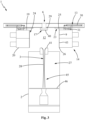
- the plant for producing non-woven fabric according to the invention comprises a support structure 2 provided with a main channel 3, which is extended along a vertical axis Y from an upper inlet mouth 4 to a lower outlet mouth 5.
- the support structure 2 is intended to be set on the ground and preferably it is made of resistant metal material, such as steel and in particular stainless steel (non-oxidizable), such as AISI 304 steel or AISI 431 steel.
- resistant metal material such as steel and in particular stainless steel (non-oxidizable), such as AISI 304 steel or AISI 431 steel.
- the main channel 3 is extended vertically along the aforesaid vertical axis Y.
- the main channel 3 can be delimited by a substantially tubular body defined, in accordance with the preferred embodiment illustrated in the enclosed figures, by a plurality of substantially tubular sections that are vertically aligned with each other along the vertical axis Y and susceptible of being crossed by filaments 7 (as described in detail hereinbelow) for the treatment thereof.
- the plant 1 comprises a feeding station 6 placed above the main channel 3 and in communication with the inlet mouth 4 in order to introduce filaments 7 in the main channel 3 for forming a non-woven fabric.
- the feeding station 6 comprises means for forming melted plastic material placed in flow connection with the inlet mouth 4 of the main channel 3 and comprising an extruder (per se known to the man skilled in the art and hence not described in detail hereinbelow), preferably supported by the support structure 2, adapted for form a continuous flow of melted plastic material and an extrusion head 29 mechanically supported by the support structure 2, placed in fluid connection with the extruder and provided with an extrusion plate facing towards the inlet mouth 4 of the main channel 3.
- the extrusion plate of the extrusion head 29 of the feeding station 6 is advantageously provided with a plurality of through holes, susceptible of being crossed by the flow of melted plastic material in order to form the filaments 7.
- the filaments 7 thus formed pass through the inlet mouth 4 and enter into the main channel 3 in order to allow a processing thereof through a plurality of operating stations, as described in detail hereinbelow.
- the plant 1, object of the present invention comprises a fumes expulsion station provided below the feeding station 6, in order to expel from the main channel 3 possible fumes produced during the extrusion of the plastic material from the extrusion head 29 through a stack (not illustrated), which connects the main channel 3 of the plant 1 with the outside environment.
- the fumes expulsion station comprises at least one expulsion duct placed to intercept the main channel 3, in particular placed in fluid communication with the extrusion plate of the extrusion head 29, in order to convey the fumes produced by the latter towards the aforesaid stack.
- the expulsion duct is adapted to convey the fumes and the vapors produced by the melted plastic material, extruded into the filaments 7 by the extrusion head, which could adhere to the internal walls of the main channel 3, forming crusts.
- the fumes expulsion station also comprises a heat exchanger of water-air type for cooling the fumes and the vapors coming from the extrusion head 29 of the feeding station 6 and for collecting a possible condensation fluid formed following such cooling.
- a heat exchanger of water-air type for cooling the fumes and the vapors coming from the extrusion head 29 of the feeding station 6 and for collecting a possible condensation fluid formed following such cooling.
- the plant 1 comprises a cooling station 8, which is placed along the aforesaid main channel 3 below the feeding station 6.
- the cooling station 8 comprises a containment body 11 extended along the vertical axis Y between an upper end 19 and a lower end 20, and is extended around the vertical axis Y, delimiting a cooling chamber 12 within the main channel 3.
- the cooling chamber 12 preferably corresponds to a first section 3' of the main channel 3.
- the cooling station 8 also comprises cooling means in fluid connection with the cooling chamber 12, adapted to introduce, in the cooling chamber 12, a first air flow 10 for cooling the filaments 7 susceptible of crossing the cooling chamber 12.
- the cooling station 8 is provided with at least one first inlet opening 9 which places the cooling chamber 12 in fluid connection with the cooling means.
- the first inlet opening 9 is provided at an internal wall 21 of the containment body 11 which delimits the main channel 3 and in particular at least partially defines the cooling chamber 12.
- the first inlet opening 9 is advantageously attained by means of a plurality of through holes made on the internal wall 21, at the first section 3' of the main channel 3.
- the internal wall 21 of the containment body 11 can be attained by means of a grill, or a cell-like wall, whose substantially checkerboard-like openings define the aforesaid first inlet opening 9.
- the cooling station 8 comprises ventilation means (not illustrated) placed in fluid connection with the first inlet opening 9 in order to introduce, within the cooling chamber 12, the first air flow 10.
- the ventilation means comprise a rotary fan, of the type per se known to the man skilled in the art and hence not described in detail hereinbelow.
- Such fan is configured for generating the first air flow 10 and introducing it within the cooling chamber 12 through the first inlet opening 9.
- the ventilation means preferably comprise a heat exchanger interposed between the fan and the first inlet opening 9.
- the heat exchanger is placed to intercept the first air flow 10 generated by the fan and it is adapted to vary the temperature and the humidity of the first air flow 10 itself.
- the heat exchanger is an exchanger of water-air type, in particular an exchanger of water-air type with tube bundle.
- the heat exchanger is adapted to bring the first air flow 10 to a constant temperature comprised between 20°C and 30°C and in particular comprised between 22°C and 25°C.
- the exchanger is mechanically supported by the support structure 2 of the plant 1 in raised position and substantially aligned with the first inlet opening 9 of the containment body 11.
- the containment body 11 comprises at least one movable portion 14, arranged in a movable manner on the support structure 2.
- the plant 1 also comprises actuator means 13 mechanically connected to the movable portion 14 and arranged for moving such movable portion 14 between a closed configuration, in which the containment body 11 perimetrically closes the cooling chamber 12 at least around the vertical axis Y, and an open configuration, in which the movable portion 14 defines at least one access opening 22 which connects the cooling chamber 12 to an outside environment.
- the actuator means 13 are of automatic type, in particular are configured for moving the movable portion 14 in an automated manner, without requiring the intervention of operators.
- the plant 1 comprises an electronic control unit electrically connected to the actuator means 13 and configured for actuating them to move the movable portion 14 of the containment body 11.
- the plant 1 also comprises a control panel, electrically connected to the electronic control unit and actuatable by an operator in order to drive the electronic control unit so as to move the movable portion 14 of the containment body 11.
- a control panel electrically connected to the electronic control unit and actuatable by an operator in order to drive the electronic control unit so as to move the movable portion 14 of the containment body 11.
- control panel connected to the electronic control unit allows the operator to drive the actuator means 13 in an automated manner without having to manually intervene at the cooling chamber 12.
- the plant 1, object of the present invention allows opening the access opening 22 for the access of at least one operator in a quick and simple manner, so as to carry out the maintenance and/or cleaning operations of the cooling chamber 12.
- the containment body 11 is provided with at least one openable side 24, which is extended between the upper end 19 and the lower end 20 and on which the access opening 22 is defined with the movable portion 14 in closed configuration.
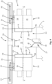
- the actuator means 13 comprise at least one pneumatic actuator 30 mechanically associated with the movable portion 14 of the containment body 11.
- the plant 1, object of the present invention comprises guide means 23 extended along a horizonal direction X substantially transverse to the vertical axis Y and slidably carrying, mounted thereon, the movable portion 14 of the containment body 11.
- the actuator means 13 are arranged for moving the movable portions 14 of the containment body along the horizonal direction X of the guide means 23 so as to move the movable portions 14 between the closed configuration and the open configuration.
- the pneumatic actuator 30 of the actuator means 13 is placed parallel to the horizonal direction X and configured for moving the movable portion 14 of the containment body 11 along the aforesaid horizonal direction X.
- the pneumatic actuator 30 of the actuator means 13 is extended between a first end 32 mechanically constrained to the support structure 2 of the plant 1 and a second end 33 mechanically constrained to the movable portion 14 of the containment body 11.
- the pneumatic actuator 30 is configured for being extended in an extended configuration in which the first end 32 constrained to the support structure 2 is moved away from the second end 33 constrained to the movable portion 14.
- the pneumatic actuator 30 is configured for being withdrawn into a retracted configuration in which the first end 32 constrained to the support structure 2 is brought close to the second end 33 constrained to the movable portion 14.
- the movable portion 14 of the containment body 11 is movable along the horizonal direction X away from and close to the vertical axis Y of the main channel 3.
- the guide means 23 comprise at least one pinion 15 rotatably constrained to the movable portion 14 of the containment body 11 and at least one rack 16 mechanically constrained to the support structure 2, engaged in a shape relationship with the pinion 15 and extended parallel to the horizonal direction X.
- the pinion 15 is rotatably mounted on a bracket 31 fixed to the movable portion 14 of the containment body 11 and it is susceptible of rotating around a substantially horizontal rotation axis thereof, substantially transverse to the horizonal direction X.
- the bracket 31 is mounted above the movable portion 14 of the containment body 11.
- the containment body 11 of the cooling station 8 comprises two movable portions 14, each movable between a closed configuration, in which they together define the cooling chamber 12 and an open configuration, in which together free the access opening 22.
- the two movable portions 14 are movable in a mirrored manner with respect to each other.
- the actuator means 13 are of linear type, mounted parallel to the horizonal direction X in order to move the movable portions 14 along the horizonal direction X.
- the actuator means can be of any type suitable to move the movable portions 14, e.g. of pneumatic type or hydraulic type.
- the plant 1 comprises motor means (not illustrated in the enclosed figures and per se well-known to the man skilled in the art) mechanically mounted on the support structure 2 and operatively connected to the actuator means 13 in order to actuate the latter to move the movable portions 14 of the containment body 11 in an automated manner.
- motor means (not illustrated in the enclosed figures and per se well-known to the man skilled in the art) mechanically mounted on the support structure 2 and operatively connected to the actuator means 13 in order to actuate the latter to move the movable portions 14 of the containment body 11 in an automated manner.
- the motor means comprise at least one electric motor mechanically connected to the actuator means 13.
- the motor means comprise at least one compressor placed in fluid connection with a pneumatic piston of the actuator means 13 and provided with an electric motor mechanically actuatable in order to activate the compressor and drive the movement of the pneumatic piston.
- the arrangement according to the invention of the actuator means 13 and of the guide means 23 for moving the movable portions 14 which define, in closed configuration, the cooling chamber 12, allows obtaining a wide opening of the latter in a simple and quick manner. Indeed, it is possible to move apart the two movable portions 14 which form the containment body 11 (which have considerable weight and bulk) by means of the simple actuation of the actuator means 13. Such movement of the movable portions 14 substantially involves the spreading apart of the containment body 11, defining a large size of the access opening 22 and a wide space between the two movable portions 14, allowing an operator to easily move himself/herself in order to execute the maintenance operations (e.g. cleaning).
- the maintenance operations e.g. cleaning
- the actuator means 13 comprise at least two pneumatic actuators 30, each mechanically associated with a corresponding movable portion 14 of the two movable portions 14 of the containment body 11.
- the two pneumatic actuators 30 are extended along a horizonal direction substantially parallel to the horizonal direction X for moving the movable portions 14.
- the guide means 23 of the plant 1 according to the invention preferably are extended along the aforesaid horizonal direction X substantially transverse to the vertical axis Y and slidably carry, mounted thereon, both the movable portions 14 of the containment body 11.
- the guide means 23 comprise at least two pinions 15, each rotatably constrained to a corresponding movable portion 14 of the two movable portions 14 of the containment body 11 and at least two racks 16 mechanically constrained to the support structure 2, each engaged in a shape relationship with a corresponding pinion 15 of the at least two pinions 15, and are extended parallel to the horizonal direction X.
- each movable portion 14 of the containment body 11 comprises a lateral portion 14', preferably with substantially box-like shape, vertically extended between the upper end 19 and the lower end 20.
- each movable portion 14 is provided with an intermediate wall 36, preferably substantially horizontal, which divides the movable portion 14 into an upper manifold 34 and a lower manifold 35.
- the upper manifold 34 is extended vertically between the upper end 19 and the intermediate wall 36 and the lower manifold is extended between the intermediate wall 36 and the lower end 20.
- the upper manifold 34 of the movable portion 14 of the containment body 11 is advantageously placed in fluid connection on one side with the ventilation means and on the other side with the cooling chamber 12 through the first inlet opening 9 and is intended to be crossed by the first air flow.
- the lower manifold 35 of the movable portion 14 of the containment body 11 is advantageously placed in fluid connection on one side with the ventilation means and on the other side with the cooling chamber 12 through a second inlet opening 43 and is intended to be crossed by a second air flow 38.
- the lower manifold 35 of the movable portion 14 of the containment body 11 is provided with a second inlet opening 43 which places the cooling chamber 12 in fluid communication with the ventilation means, and susceptible of being crossed by the second air flow 38.
- the movable portion 14 of the containment body 11 preferably comprises at least one door 39 which projectingly protrudes from a perimeter edge of the internal wall 21 of the containment body 11, in order to close the cooling chamber 12 with the movable portion 14 in the closed configuration.
- the door 39 is extended vertically between the upper end 19 and the lower end 20 and defines the cooling chamber 12 together with the internal wall 21 of the containment body 11.
- each movable portion 14 is extended advantageously along a plane substantially orthogonal to the horizonal direction X.
- the openable side 24 of the containment body 11 is defined by an external edge of the door 39.
- each movable portion 14 comprises an aforesaid internal wall 21 (directed towards the internal wall 21 of the other movable portion 14) and preferably two doors 39 placed on opposite sides of the movable portion 14 and each adapted to close the cooling chamber 12, interacting with the corresponding door of the other movable portion.
- the plant 1, object of the present invention preferably comprises sealing means 17 operatively associated with the at least one movable portion 14 and configured for tightly sealing the cooling chamber 12 with respect to the outside environment with the at least one movable portion 14 in the closed configuration.
- the sealing means 17 comprise at least one inflatable seal 40, 41.
- inflatable seal it must be intended hereinbelow any type of seal which internally defines an expansion chamber configured for housing a pressurized fluid at its interior.
- the inflatable seal 40, 41 is movable between an expanded configuration, in which the pressurized fluid housed in the expansion chamber increases the volume occupied by the inflatable seal 40, 41 itself, and a retracted configuration, in which the expansion chamber substantially does not house fluid, decreasing the volume occupied by the inflatable seal 40, 41 itself.
- the sealing means 17 of the plant 1, object of the present invention preferably comprises a pressurized fluid circuit, placed in fluid connection with the inflatable seal.
- the circuit can be of pneumatic type, in which it is provided to feed pressurized air within the expansion chamber of the inflatable seal.
- the circuit can be of oil-pressure type, in which it is provided to feed oil under pressure within the expansion chamber of the inflatable seal.
- the pressurized fluid circuit can be driven in order to introduce the fluid within the expansion chamber of the inflatable seal, so as to move the seal itself from the retracted configuration to the expanded configuration.
- the movable portion 14 is provided with an upper edge 25 at its upper end 19 which at least partially delimits the inlet mouth 4, with the movable portion 14 in the closed configuration.
- the upper edge 25 is directed towards the feeding station 6 and in particular delimits the inlet mouth 4 for the passage of the filaments 7 formed by the extrusion plate.
- the sealing means 17 comprise a first inflatable seal 40 which acts in abutment against the upper edge 25 with the movable portion 14 in the closed configuration.
- the first inflatable seal 40 is advantageously placed around the extrusion plate of the feeding station 6 and preferably projects downward.
- the movable portion 14 of the containment body 11 is provided with a lower edge 26 at the lower end 20.
- the sealing means 17 advantageously comprise a second inflatable seal 41 which acts in abutment against the lower edge 26 with the movable portion 14 in the closed configuration.
- the plant 1, object of the present invention comprises an elongating station 27 provided with a stretching duct 28 extended along said vertical axis Y mechanically associated with the lower edge 26 of the containment body 11.
- the second inflatable seal 41 is interposed between the lower edge 26 of the containment body 11 and the stretching duct 28 of the elongating station 27.
- the pressurized fluid circuit is configured for thrusting pressurized air within the expansion chamber of the inflatable seal in order to move it from the retracted configuration to the expanded configuration.
- the sealing means 17 comprise a third inflatable seal 47 mechanically fixed to the door 39.
- the third inflatable seal 47 is fixed to an external edge of the door 39 and is extended between the upper end 19 and the lower end 20 and is configured for acting in abutment against a corresponding external edge of the other door 39 of the other movable portion 14, or, otherwise, for acting in abutment against an edge of the internal wall 21 of the containment body 11.
- the sealing means advantageously comprise suction means placed in fluid connection with the expansion chamber of the inflatable seal.
- suction means are actuatable for removing the pressurized fluid housed in the expansion chamber, reducing the volume occupied by the inflatable seal itself.
- the plant 1, object of the present invention also comprises a deposition station placed below the elongating station 27, along the main channel 3 and which terminates with the outlet mouth 5 for the filaments 7.
- the deposition station comprises a diffuser 45, which defines a third section 3′′′ of the main channel 3 of the plant 1.
- the diffuser 45 of the deposition station is extended, widening starting from the elongating station 27, terminating with the outlet mouth 5 for the filaments 7 in order to deposit them on a conveyor belt 46.
- the filaments 7 which cross through the diffuser 45 of the deposition station tend to be woven with each other, and are therefore deposited on the conveyor belt 46 in non-woven fabric web form.
Landscapes
- Engineering & Computer Science (AREA)
- Textile Engineering (AREA)
- Mechanical Engineering (AREA)
- Nonwoven Fabrics (AREA)
- Treatment Of Fiber Materials (AREA)
Claims (12)
- Anlage zur Herstellung von Vliesstoff, die Folgendes umfasst:- eine Tragstruktur (2), die mit einem Hauptkanal (3) ausgestattet ist, der sich entlang einer Vertikalachse (Y) zwischen einer oberen Eingangsmündung (4) und einer unteren Ausgangsmündung (5) erstreckt;- eine Zuführstation (6), die auf dem genannten Hauptkanal (3) und in Verbindung mit der genannten Eingangsmündung (4) angebracht ist, um in den genannten Hauptkanal (3) Formfäden (7) eines Vliesstoffes einzuführen;- eine Kühlstation (8), die entlang des genannten Hauptkanals (3) unter der genannten Zuführstation (6) angebracht ist und Folgendes umfasst:- einen Aufnahmekörper (11), der entlang der genannten Vertikalachse (Y) zwischen einem oberen Ende (19) und einem unteren Ende (20) verläuft und sich um die genannte Vertikalachse (Y) erstreckt, wobei er eine Kühlkammer (12) im genannten Hauptkanal (3) begrenzt;- Kühleinrichtungen in Flüssigkeitsverbindung mit der genannten Kühlkammer (12), die geeignet sind, in die genannte Kühlkammer (12) einen ersten Luftfluss (10) einzuführen, um die Fäden (7) zu kühlen, die geeignet sind, die genannte Kühlkammer (12) zu durchqueren;wobei die genannte Anlage dadurch gekennzeichnet ist, dass:- der genannte Aufnahmekörper (11) mindestens zwei bewegliche Abschnitte (14) umfasst, die beweglich auf der genannten Tragstruktur (2) eingerichtet sind;- die genannte Anlage außerdem Antriebselemente (13) enthält, die mechanisch mit den genannten mindestens zwei beweglichen Abschnitten (14) verbunden und ausgelegt sind, um die genannten mindestens zwei beweglichen Anteile (14) von einer geschlossenen Konfiguration, in der der genannte Aufnahmekörper (11) die genannte Kühlkammer (12) umlaufend mindestens um die genannte Vertikalachse (Y) schließt, und einer offenen Konfiguration, in der der genannte mindestens eine bewegliche Abschnitt (14) mindestens eine Zugangsöffnung (22) definiert, die die genannte Kühlkammer (12) mit einer Außenumgebung verbindet, zu bewegen;- die genannten beweglichen Abschnitte (14) in der genannten geschlossenen Konfiguration zusammen die genannte Kühlkammer (12) definieren und dass die genannten beweglichen Abschnitte (14) in der genannten offenen Konfiguration zusammen die genannte Zugangsöffnung (22) direkt zugänglich machen;- die genannte Anlage Führungselemente (23) umfasst, die entlang einer horizontalen Richtung (X) im Wesentlichen quer zur genannten Vertikalachse (Y) verlaufen, und den genannten beweglichen Abschnitten (14) des genannten Aufnahmekörpers (11) gleitend tragen;wobei jeder bewegliche Abschnitt (14) des genannten Aufnahmekörpers (11) Folgendes umfasst:- eine Innenwand (21), die sich quer zur genannten horizontalen Richtung (X) erstreckt und die vor der Innenwand (21) des anderen genannten beweglichen Abschnitts (14) angebracht ist, wobei die Innenwände (21) der genannten beweglichen Abschnitte (14) miteinander die genannte Kühlkammer (12) entlang der genannten horizontalen Richtung (X) begrenzen, und- mindestens eine Tür (39), die aus einem Umgangsrand der Innenwand (21) des genannten Aufnahmekörpers (11) vorsteht und die geeignet ist, die genannte Kühlkammer (12) mit dem genannten beweglichen Abschnitt (14) in der genannten geschlossenen Konfiguration zu schließen;wobei die genannte Kühlstation (8) mit mindestens einer ersten Eingangsmündung (9) ausgestattet ist, die die genannte Kühlkammer (12) in Flüssigkeitsverbindung mit den genannten Kühleinrichtungen setzt; die genannte erste Eingangsmündung (9) ist an der Innenwand (21) jedes beweglichen Abschnitts (14) des genannten Aufnahmekörpers (11) vorgesehen.
- Anlage zur Herstellung von Vliesstoff nach Anspruch 1, dadurch gekennzeichnet, dass die genannten Antriebselemente (13) mindestens einen pneumatischen Stellantrieb (15) umfassen, der mechanisch mit dem genannten beweglichen Abschnitt (14) des genannten Aufnahmekörpers (11) verbunden ist.
- Anlage zur Herstellung von Vliesstoff nach Anspruch 1 oder 2, dadurch gekennzeichnet, dass die genannten Antriebselemente (13) automatisch sind und konfiguriert wurden, um die beweglichen Abschnitte (14) automatisch zu bewegen.
- Anlage zur Herstellung von Vliesstoff nach Anspruch 3, dadurch gekennzeichnet, dass die genannten Antriebselemente (13) linear sind und parallel zur genannten horizontalen Richtung (X) montiert wurden, um die genannten beweglichen Abschnitte entlang der genannten horizontalen Richtung (X) zu bewegen.
- Anlage zur Herstellung von Vliesstoff nach Anspruch 3 oder 4, dadurch gekennzeichnet, dass sie Antriebselemente umfassen, die mechanisch auf der genannten Tragstruktur (2) montiert und operativ mit den genannten Antriebselementen (13) verbunden sind, um die genannten Antriebselemente (13) zu betätigen, damit sie die beweglichen Abschnitte (14) des genannten Aufnahmekörpers (11) automatisch bewegen.
- Anlage zur Herstellung von Vliesstoff nach einem der vorangegangenen Ansprüche, dadurch gekennzeichnet, dass die genannten Führungselemente (23) mindestens ein Ritzel (15) umfassen, das drehbar mit dem genannten beweglichen Abschnitt (14) des genannten Aufnahmekörpers (11) verbunden ist, und mindestens eine Zahnstange (16), die mechanisch mit der genannten Tragstruktur (2) verbunden ist, die formschlüssig mit dem genannten mindestens einen Ritzel (15) verbunden ist und sich parallel zur genannten horizontalen Richtung (X) erstreckt.
- Anlage zur Herstellung von Vliesstoff nach einem der vorangegangenen Ansprüche, dadurch gekennzeichnet, dass der genannte Aufnahmekörper (11) mit mindestens einer zu öffnenden Seite (24) ausgestattet ist, die sich zwischen dem genannten oberen Ende (19) und dem genannten unteren Ende (20) erstreckt und auf der die genannte Zugangsöffnung (22) mit dem genannten beweglichen Abschnitt (14) in der offenen Konfiguration definiert ist.
- Anlage zur Herstellung von Vliesstoff nach einem der vorangegangenen Ansprüche, dadurch gekennzeichnet, dass sie Dichtungselemente (17) umfasst, die operativ mit dem genannten mindestens einen beweglichen Abschnitt (14) verbunden sind und konfiguriert sind, um die genannte Kühlkammer (12) von der Außenumgebung mit dem genannten mindestens einen beweglichen Abschnitt (14) in der genannten geschlossenen Konfiguration abzudichten.
- Anlage zur Herstellung von Vliesstoff nach Anspruch 8, dadurch gekennzeichnet, dass die genannten Dichtungselemente (17) mindestens eine aufblasbare Dichtung umfassen.
- Anlage zur Herstellung von Vliesstoff nach Anspruch 9, dadurch gekennzeichnet, dass der genannte bewegliche Abschnitt (14) mit einem oberen Rand (25) am genannten oberen Ende (19) ausgestattet ist, der mindestens teilweise die genannte Eingangsmündung (4) mit dem genannten beweglichen Abschnitt (14) in der genannten geschlossenen Konfiguration begrenzt;
wobei die genannten Dichtungselemente (17) eine erste aufblasbare Dichtung umfassen, die anschlagend gegen den genannten oberen Rand (25) mit dem genannten beweglichen Abschnitt (14) in der geschlossenen Konfiguration wirkt. - Anlage zur Herstellung von Vliesstoff nach Anspruch 9 oder 10, dadurch gekennzeichnet, dass der genannte bewegliche Abschnitt (14) mit einem unteren Rand (26) am genannten unteren Ende (20) ausgestattet ist;
wobei die genannten Dichtungselemente (17) eine zweite aufblasbare Dichtung umfassen, die anschlagend gegen den genannten unteren Rand (26) mit dem genannten beweglichen Abschnitt (14) in der geschlossenen Konfiguration wirkt. - Anlage zur Herstellung von Vliesstoff nach Anspruch 11, dadurch gekennzeichnet, dass sie eine Verlängerungsstation (27) umfasst, die mit einem Verstreckschacht (28) ausgestattet ist, der entlang der genannten Vertikalachse (Y) verläuft, die mechanisch mit dem unteren Rand (26) des genannten Aufnahmekörpers (11) verbunden ist;
wobei die zweite aufblasbare Dichtung zwischen dem genannten unteren Rand (26) des genannten Aufnahmekörpers (11) und dem genannten Verstreckschacht (28) der genannten Verlängerungsstation (27) angebracht ist.
Applications Claiming Priority (1)
| Application Number | Priority Date | Filing Date | Title |
|---|---|---|---|
| IT102019000004767A IT201900004767A1 (it) | 2019-03-29 | 2019-03-29 | Impianto per la produzione di tessuto non tessuto |
Publications (2)
| Publication Number | Publication Date |
|---|---|
| EP3715518A1 EP3715518A1 (de) | 2020-09-30 |
| EP3715518B1 true EP3715518B1 (de) | 2024-01-10 |
Family
ID=67108042
Family Applications (1)
| Application Number | Title | Priority Date | Filing Date |
|---|---|---|---|
| EP20164754.2A Active EP3715518B1 (de) | 2019-03-29 | 2020-03-22 | Anlage zur herstellung von vliesstoff |
Country Status (2)
| Country | Link |
|---|---|
| EP (1) | EP3715518B1 (de) |
| IT (1) | IT201900004767A1 (de) |
Family Cites Families (7)
| Publication number | Priority date | Publication date | Assignee | Title |
|---|---|---|---|---|
| NL289560A (de) * | 1963-02-27 | |||
| US3169271A (en) * | 1963-09-13 | 1965-02-16 | Du Pont | Apparatus for quenching extruded spinneret filaments |
| US4405297A (en) * | 1980-05-05 | 1983-09-20 | Kimberly-Clark Corporation | Apparatus for forming nonwoven webs |
| DE19924508C1 (de) * | 1999-05-28 | 2000-11-30 | Johns Manville Int Inc | Vorrichtung zum Herstellen eines Spinnvlieses durch Spinnen aus einer Überdruckkammer |
| DE10322460B4 (de) * | 2003-05-16 | 2007-02-08 | Corovin Gmbh | Verfahren und Vorrichtung zur Herstellung eines Spinnvlieses aus Filamenten aus aufgeplatzten Fasern, Filamente aus aufgeplatzen Fasern und Vliesstoff |
| DE502012009274C5 (de) | 2011-10-22 | 2022-01-20 | Oerlikon Textile Gmbh & Co. Kg | Vorrichtung und Verfahren zum Führen und Ablegen von synthetischen Filamenten zu einem Vlies |
| EP3382082B1 (de) * | 2017-03-31 | 2019-08-07 | Reifenhäuser GmbH & Co. KG Maschinenfabrik | Vorrichtung zur herstellung von spinnvliesen aus endlosfilamenten |
-
2019
- 2019-03-29 IT IT102019000004767A patent/IT201900004767A1/it unknown
-
2020
- 2020-03-22 EP EP20164754.2A patent/EP3715518B1/de active Active
Also Published As
| Publication number | Publication date |
|---|---|
| EP3715518A1 (de) | 2020-09-30 |
| IT201900004767A1 (it) | 2020-09-29 |
Similar Documents
| Publication | Publication Date | Title |
|---|---|---|
| DE60207607T2 (de) | Verfahren und maschine zum verpacken von produkten mit dehnbarer thermoplastfolie | |
| EP2287077B1 (de) | Lasersiegeln von Verpackungen | |
| EP2099959B1 (de) | Verfahren und vorrichtung zur herstellung eines vliesstoffes aus extrudierten fasern | |
| EP0710605B1 (de) | Verfahren und Vorrichtung zum Maximieren der Taktgeschwindigkeit einer Vakuumverpackungsmaschine | |
| EP2683617B1 (de) | Verfahren und vorrichtung zum verschliessen eines sackes | |
| EP3831989B1 (de) | Anlage zur herstellung von vliesstoffen | |
| EP1448466B1 (de) | Vorrichtung zum gleichzeitigen fördern und temperieren von formteilen | |
| EP3715518B1 (de) | Anlage zur herstellung von vliesstoff | |
| CN102066199A (zh) | 用于制造和填充容器的设备 | |
| EP4335759A2 (de) | Tiefziehverpackungsmaschine mit vakuumkühlstation und verfahren zum vakuumkühlen heissverpackter produkte | |
| EP3085512B1 (de) | Extruderhaube für pneumatisches fördersystem | |
| US20050161387A1 (en) | Filter device method of manufacturing the same and method of replacing a filter device | |
| CN111469381A (zh) | 一种人工化的进出料的自动吹塑机 | |
| DE102012018974A1 (de) | Tiefziehverpackungsmaschine mit Stempelformung | |
| EP4124685B1 (de) | Anlage zur herstellung von vliesstoffen | |
| EP3921585B1 (de) | Trocknungseinrichtung und trocknungsverfahren für eine textile warenbahn | |
| EP4148169A2 (de) | Anlage zur herstellung von vliesstoffen | |
| EP3865613B1 (de) | Anlage zur herstellung eines vliesstoffs und verfahren zur herstellung eines vliesstoffs | |
| CN114108188A (zh) | 一种pet双取向熔喷非织造布及其制备工艺 | |
| EP0950499B1 (de) | Verfahren zur Herstellung von oberflächenreinen Blasfolien sowie Einrichtung zur Durchführung des Verfahrens | |
| CN208438753U (zh) | 烟用pe热收缩膜生产设备 | |
| DE102005048491A1 (de) | Verpackungsmaschine und Verfahren zur Herstellung von Mehrlagenfolienverpackungen | |
| EP1331291A2 (de) | Texturieranlage und Texturierdüse hierfür | |
| EP2020456A1 (de) | Vorrichtung und Verfahren zur Herstellung synthetischer Garne | |
| EP4141152A1 (de) | Anlage zur herstellung eines vliesstoffs |
Legal Events
| Date | Code | Title | Description |
|---|---|---|---|
| PUAI | Public reference made under article 153(3) epc to a published international application that has entered the european phase |
Free format text: ORIGINAL CODE: 0009012 |
|
| STAA | Information on the status of an ep patent application or granted ep patent |
Free format text: STATUS: THE APPLICATION HAS BEEN PUBLISHED |
|
| AK | Designated contracting states |
Kind code of ref document: A1 Designated state(s): AL AT BE BG CH CY CZ DE DK EE ES FI FR GB GR HR HU IE IS IT LI LT LU LV MC MK MT NL NO PL PT RO RS SE SI SK SM TR |
|
| AX | Request for extension of the european patent |
Extension state: BA ME |
|
| STAA | Information on the status of an ep patent application or granted ep patent |
Free format text: STATUS: REQUEST FOR EXAMINATION WAS MADE |
|
| 17P | Request for examination filed |
Effective date: 20210330 |
|
| RBV | Designated contracting states (corrected) |
Designated state(s): AL AT BE BG CH CY CZ DE DK EE ES FI FR GB GR HR HU IE IS IT LI LT LU LV MC MK MT NL NO PL PT RO RS SE SI SK SM TR |
|
| P01 | Opt-out of the competence of the unified patent court (upc) registered |
Effective date: 20230302 |
|
| GRAP | Despatch of communication of intention to grant a patent |
Free format text: ORIGINAL CODE: EPIDOSNIGR1 |
|
| STAA | Information on the status of an ep patent application or granted ep patent |
Free format text: STATUS: GRANT OF PATENT IS INTENDED |
|
| INTG | Intention to grant announced |
Effective date: 20230731 |
|
| GRAS | Grant fee paid |
Free format text: ORIGINAL CODE: EPIDOSNIGR3 |
|
| GRAA | (expected) grant |
Free format text: ORIGINAL CODE: 0009210 |
|
| STAA | Information on the status of an ep patent application or granted ep patent |
Free format text: STATUS: THE PATENT HAS BEEN GRANTED |
|
| AK | Designated contracting states |
Kind code of ref document: B1 Designated state(s): AL AT BE BG CH CY CZ DE DK EE ES FI FR GB GR HR HU IE IS IT LI LT LU LV MC MK MT NL NO PL PT RO RS SE SI SK SM TR |
|
| REG | Reference to a national code |
Ref country code: GB Ref legal event code: FG4D |
|
| REG | Reference to a national code |
Ref country code: CH Ref legal event code: EP |
|
| REG | Reference to a national code |
Ref country code: DE Ref legal event code: R096 Ref document number: 602020024083 Country of ref document: DE |
|
| REG | Reference to a national code |
Ref country code: IE Ref legal event code: FG4D |
|
| REG | Reference to a national code |
Ref country code: LT Ref legal event code: MG9D |
|
| REG | Reference to a national code |
Ref country code: NL Ref legal event code: MP Effective date: 20240110 |
|
| REG | Reference to a national code |
Ref country code: AT Ref legal event code: MK05 Ref document number: 1648962 Country of ref document: AT Kind code of ref document: T Effective date: 20240110 |
|
| PG25 | Lapsed in a contracting state [announced via postgrant information from national office to epo] |
Ref country code: NL Free format text: LAPSE BECAUSE OF FAILURE TO SUBMIT A TRANSLATION OF THE DESCRIPTION OR TO PAY THE FEE WITHIN THE PRESCRIBED TIME-LIMIT Effective date: 20240110 |
|
| PG25 | Lapsed in a contracting state [announced via postgrant information from national office to epo] |
Ref country code: NL Free format text: LAPSE BECAUSE OF FAILURE TO SUBMIT A TRANSLATION OF THE DESCRIPTION OR TO PAY THE FEE WITHIN THE PRESCRIBED TIME-LIMIT Effective date: 20240110 |
|
| PG25 | Lapsed in a contracting state [announced via postgrant information from national office to epo] |
Ref country code: IS Free format text: LAPSE BECAUSE OF FAILURE TO SUBMIT A TRANSLATION OF THE DESCRIPTION OR TO PAY THE FEE WITHIN THE PRESCRIBED TIME-LIMIT Effective date: 20240510 |
|
| PG25 | Lapsed in a contracting state [announced via postgrant information from national office to epo] |
Ref country code: LT Free format text: LAPSE BECAUSE OF FAILURE TO SUBMIT A TRANSLATION OF THE DESCRIPTION OR TO PAY THE FEE WITHIN THE PRESCRIBED TIME-LIMIT Effective date: 20240110 |
|
| PG25 | Lapsed in a contracting state [announced via postgrant information from national office to epo] |
Ref country code: GR Free format text: LAPSE BECAUSE OF FAILURE TO SUBMIT A TRANSLATION OF THE DESCRIPTION OR TO PAY THE FEE WITHIN THE PRESCRIBED TIME-LIMIT Effective date: 20240411 |
|
| PG25 | Lapsed in a contracting state [announced via postgrant information from national office to epo] |
Ref country code: RS Free format text: LAPSE BECAUSE OF FAILURE TO SUBMIT A TRANSLATION OF THE DESCRIPTION OR TO PAY THE FEE WITHIN THE PRESCRIBED TIME-LIMIT Effective date: 20240410 Ref country code: HR Free format text: LAPSE BECAUSE OF FAILURE TO SUBMIT A TRANSLATION OF THE DESCRIPTION OR TO PAY THE FEE WITHIN THE PRESCRIBED TIME-LIMIT Effective date: 20240110 |
|
| PG25 | Lapsed in a contracting state [announced via postgrant information from national office to epo] |
Ref country code: ES Free format text: LAPSE BECAUSE OF FAILURE TO SUBMIT A TRANSLATION OF THE DESCRIPTION OR TO PAY THE FEE WITHIN THE PRESCRIBED TIME-LIMIT Effective date: 20240110 |
|
| PG25 | Lapsed in a contracting state [announced via postgrant information from national office to epo] |
Ref country code: AT Free format text: LAPSE BECAUSE OF FAILURE TO SUBMIT A TRANSLATION OF THE DESCRIPTION OR TO PAY THE FEE WITHIN THE PRESCRIBED TIME-LIMIT Effective date: 20240110 |
|
| PG25 | Lapsed in a contracting state [announced via postgrant information from national office to epo] |
Ref country code: RS Free format text: LAPSE BECAUSE OF FAILURE TO SUBMIT A TRANSLATION OF THE DESCRIPTION OR TO PAY THE FEE WITHIN THE PRESCRIBED TIME-LIMIT Effective date: 20240410 Ref country code: NO Free format text: LAPSE BECAUSE OF FAILURE TO SUBMIT A TRANSLATION OF THE DESCRIPTION OR TO PAY THE FEE WITHIN THE PRESCRIBED TIME-LIMIT Effective date: 20240410 Ref country code: LT Free format text: LAPSE BECAUSE OF FAILURE TO SUBMIT A TRANSLATION OF THE DESCRIPTION OR TO PAY THE FEE WITHIN THE PRESCRIBED TIME-LIMIT Effective date: 20240110 Ref country code: IS Free format text: LAPSE BECAUSE OF FAILURE TO SUBMIT A TRANSLATION OF THE DESCRIPTION OR TO PAY THE FEE WITHIN THE PRESCRIBED TIME-LIMIT Effective date: 20240510 Ref country code: HR Free format text: LAPSE BECAUSE OF FAILURE TO SUBMIT A TRANSLATION OF THE DESCRIPTION OR TO PAY THE FEE WITHIN THE PRESCRIBED TIME-LIMIT Effective date: 20240110 Ref country code: GR Free format text: LAPSE BECAUSE OF FAILURE TO SUBMIT A TRANSLATION OF THE DESCRIPTION OR TO PAY THE FEE WITHIN THE PRESCRIBED TIME-LIMIT Effective date: 20240411 Ref country code: ES Free format text: LAPSE BECAUSE OF FAILURE TO SUBMIT A TRANSLATION OF THE DESCRIPTION OR TO PAY THE FEE WITHIN THE PRESCRIBED TIME-LIMIT Effective date: 20240110 Ref country code: BG Free format text: LAPSE BECAUSE OF FAILURE TO SUBMIT A TRANSLATION OF THE DESCRIPTION OR TO PAY THE FEE WITHIN THE PRESCRIBED TIME-LIMIT Effective date: 20240110 Ref country code: AT Free format text: LAPSE BECAUSE OF FAILURE TO SUBMIT A TRANSLATION OF THE DESCRIPTION OR TO PAY THE FEE WITHIN THE PRESCRIBED TIME-LIMIT Effective date: 20240110 |
|
| PG25 | Lapsed in a contracting state [announced via postgrant information from national office to epo] |
Ref country code: PL Free format text: LAPSE BECAUSE OF FAILURE TO SUBMIT A TRANSLATION OF THE DESCRIPTION OR TO PAY THE FEE WITHIN THE PRESCRIBED TIME-LIMIT Effective date: 20240110 Ref country code: PT Free format text: LAPSE BECAUSE OF FAILURE TO SUBMIT A TRANSLATION OF THE DESCRIPTION OR TO PAY THE FEE WITHIN THE PRESCRIBED TIME-LIMIT Effective date: 20240510 |
|
| PG25 | Lapsed in a contracting state [announced via postgrant information from national office to epo] |
Ref country code: SE Free format text: LAPSE BECAUSE OF FAILURE TO SUBMIT A TRANSLATION OF THE DESCRIPTION OR TO PAY THE FEE WITHIN THE PRESCRIBED TIME-LIMIT Effective date: 20240110 Ref country code: PT Free format text: LAPSE BECAUSE OF FAILURE TO SUBMIT A TRANSLATION OF THE DESCRIPTION OR TO PAY THE FEE WITHIN THE PRESCRIBED TIME-LIMIT Effective date: 20240510 Ref country code: PL Free format text: LAPSE BECAUSE OF FAILURE TO SUBMIT A TRANSLATION OF THE DESCRIPTION OR TO PAY THE FEE WITHIN THE PRESCRIBED TIME-LIMIT Effective date: 20240110 Ref country code: LV Free format text: LAPSE BECAUSE OF FAILURE TO SUBMIT A TRANSLATION OF THE DESCRIPTION OR TO PAY THE FEE WITHIN THE PRESCRIBED TIME-LIMIT Effective date: 20240110 |
|
| PG25 | Lapsed in a contracting state [announced via postgrant information from national office to epo] |
Ref country code: DK Free format text: LAPSE BECAUSE OF FAILURE TO SUBMIT A TRANSLATION OF THE DESCRIPTION OR TO PAY THE FEE WITHIN THE PRESCRIBED TIME-LIMIT Effective date: 20240110 |
|
| REG | Reference to a national code |
Ref country code: DE Ref legal event code: R097 Ref document number: 602020024083 Country of ref document: DE |
|
| PG25 | Lapsed in a contracting state [announced via postgrant information from national office to epo] |
Ref country code: SM Free format text: LAPSE BECAUSE OF FAILURE TO SUBMIT A TRANSLATION OF THE DESCRIPTION OR TO PAY THE FEE WITHIN THE PRESCRIBED TIME-LIMIT Effective date: 20240110 |
|
| PG25 | Lapsed in a contracting state [announced via postgrant information from national office to epo] |
Ref country code: EE Free format text: LAPSE BECAUSE OF FAILURE TO SUBMIT A TRANSLATION OF THE DESCRIPTION OR TO PAY THE FEE WITHIN THE PRESCRIBED TIME-LIMIT Effective date: 20240110 Ref country code: CZ Free format text: LAPSE BECAUSE OF FAILURE TO SUBMIT A TRANSLATION OF THE DESCRIPTION OR TO PAY THE FEE WITHIN THE PRESCRIBED TIME-LIMIT Effective date: 20240110 |
|
| PG25 | Lapsed in a contracting state [announced via postgrant information from national office to epo] |
Ref country code: SK Free format text: LAPSE BECAUSE OF FAILURE TO SUBMIT A TRANSLATION OF THE DESCRIPTION OR TO PAY THE FEE WITHIN THE PRESCRIBED TIME-LIMIT Effective date: 20240110 |
|
| PG25 | Lapsed in a contracting state [announced via postgrant information from national office to epo] |
Ref country code: SM Free format text: LAPSE BECAUSE OF FAILURE TO SUBMIT A TRANSLATION OF THE DESCRIPTION OR TO PAY THE FEE WITHIN THE PRESCRIBED TIME-LIMIT Effective date: 20240110 Ref country code: SK Free format text: LAPSE BECAUSE OF FAILURE TO SUBMIT A TRANSLATION OF THE DESCRIPTION OR TO PAY THE FEE WITHIN THE PRESCRIBED TIME-LIMIT Effective date: 20240110 Ref country code: RO Free format text: LAPSE BECAUSE OF FAILURE TO SUBMIT A TRANSLATION OF THE DESCRIPTION OR TO PAY THE FEE WITHIN THE PRESCRIBED TIME-LIMIT Effective date: 20240110 Ref country code: EE Free format text: LAPSE BECAUSE OF FAILURE TO SUBMIT A TRANSLATION OF THE DESCRIPTION OR TO PAY THE FEE WITHIN THE PRESCRIBED TIME-LIMIT Effective date: 20240110 Ref country code: DK Free format text: LAPSE BECAUSE OF FAILURE TO SUBMIT A TRANSLATION OF THE DESCRIPTION OR TO PAY THE FEE WITHIN THE PRESCRIBED TIME-LIMIT Effective date: 20240110 Ref country code: CZ Free format text: LAPSE BECAUSE OF FAILURE TO SUBMIT A TRANSLATION OF THE DESCRIPTION OR TO PAY THE FEE WITHIN THE PRESCRIBED TIME-LIMIT Effective date: 20240110 |
|
| REG | Reference to a national code |
Ref country code: CH Ref legal event code: PL |
|
| PLBE | No opposition filed within time limit |
Free format text: ORIGINAL CODE: 0009261 |
|
| STAA | Information on the status of an ep patent application or granted ep patent |
Free format text: STATUS: NO OPPOSITION FILED WITHIN TIME LIMIT |
|
| PG25 | Lapsed in a contracting state [announced via postgrant information from national office to epo] |
Ref country code: LU Free format text: LAPSE BECAUSE OF NON-PAYMENT OF DUE FEES Effective date: 20240322 |
|
| PG25 | Lapsed in a contracting state [announced via postgrant information from national office to epo] |
Ref country code: MC Free format text: LAPSE BECAUSE OF FAILURE TO SUBMIT A TRANSLATION OF THE DESCRIPTION OR TO PAY THE FEE WITHIN THE PRESCRIBED TIME-LIMIT Effective date: 20240110 |
|
| PG25 | Lapsed in a contracting state [announced via postgrant information from national office to epo] |
Ref country code: MC Free format text: LAPSE BECAUSE OF FAILURE TO SUBMIT A TRANSLATION OF THE DESCRIPTION OR TO PAY THE FEE WITHIN THE PRESCRIBED TIME-LIMIT Effective date: 20240110 Ref country code: LU Free format text: LAPSE BECAUSE OF NON-PAYMENT OF DUE FEES Effective date: 20240322 |
|
| PG25 | Lapsed in a contracting state [announced via postgrant information from national office to epo] |
Ref country code: IT Free format text: LAPSE BECAUSE OF FAILURE TO SUBMIT A TRANSLATION OF THE DESCRIPTION OR TO PAY THE FEE WITHIN THE PRESCRIBED TIME-LIMIT Effective date: 20240110 |
|
| REG | Reference to a national code |
Ref country code: BE Ref legal event code: MM Effective date: 20240331 |
|
| 26N | No opposition filed |
Effective date: 20241011 |
|
| GBPC | Gb: european patent ceased through non-payment of renewal fee |
Effective date: 20240410 |
|
| PG25 | Lapsed in a contracting state [announced via postgrant information from national office to epo] |
Ref country code: IT Free format text: LAPSE BECAUSE OF FAILURE TO SUBMIT A TRANSLATION OF THE DESCRIPTION OR TO PAY THE FEE WITHIN THE PRESCRIBED TIME-LIMIT Effective date: 20240110 |
|
| PG25 | Lapsed in a contracting state [announced via postgrant information from national office to epo] |
Ref country code: BE Free format text: LAPSE BECAUSE OF NON-PAYMENT OF DUE FEES Effective date: 20240331 |
|
| PG25 | Lapsed in a contracting state [announced via postgrant information from national office to epo] |
Ref country code: GB Free format text: LAPSE BECAUSE OF NON-PAYMENT OF DUE FEES Effective date: 20240410 |
|
| PG25 | Lapsed in a contracting state [announced via postgrant information from national office to epo] |
Ref country code: FR Free format text: LAPSE BECAUSE OF NON-PAYMENT OF DUE FEES Effective date: 20240331 |
|
| PG25 | Lapsed in a contracting state [announced via postgrant information from national office to epo] |
Ref country code: IE Free format text: LAPSE BECAUSE OF NON-PAYMENT OF DUE FEES Effective date: 20240322 |
|
| PG25 | Lapsed in a contracting state [announced via postgrant information from national office to epo] |
Ref country code: IE Free format text: LAPSE BECAUSE OF NON-PAYMENT OF DUE FEES Effective date: 20240322 Ref country code: GB Free format text: LAPSE BECAUSE OF NON-PAYMENT OF DUE FEES Effective date: 20240410 Ref country code: FR Free format text: LAPSE BECAUSE OF NON-PAYMENT OF DUE FEES Effective date: 20240331 Ref country code: BE Free format text: LAPSE BECAUSE OF NON-PAYMENT OF DUE FEES Effective date: 20240331 Ref country code: CH Free format text: LAPSE BECAUSE OF NON-PAYMENT OF DUE FEES Effective date: 20240331 |
|
| PG25 | Lapsed in a contracting state [announced via postgrant information from national office to epo] |
Ref country code: SI Free format text: LAPSE BECAUSE OF FAILURE TO SUBMIT A TRANSLATION OF THE DESCRIPTION OR TO PAY THE FEE WITHIN THE PRESCRIBED TIME-LIMIT Effective date: 20240110 |
|
| PG25 | Lapsed in a contracting state [announced via postgrant information from national office to epo] |
Ref country code: CY Free format text: LAPSE BECAUSE OF FAILURE TO SUBMIT A TRANSLATION OF THE DESCRIPTION OR TO PAY THE FEE WITHIN THE PRESCRIBED TIME-LIMIT; INVALID AB INITIO Effective date: 20200322 |
|
| PG25 | Lapsed in a contracting state [announced via postgrant information from national office to epo] |
Ref country code: HU Free format text: LAPSE BECAUSE OF FAILURE TO SUBMIT A TRANSLATION OF THE DESCRIPTION OR TO PAY THE FEE WITHIN THE PRESCRIBED TIME-LIMIT; INVALID AB INITIO Effective date: 20200322 |
|
| PG25 | Lapsed in a contracting state [announced via postgrant information from national office to epo] |
Ref country code: FI Free format text: LAPSE BECAUSE OF FAILURE TO SUBMIT A TRANSLATION OF THE DESCRIPTION OR TO PAY THE FEE WITHIN THE PRESCRIBED TIME-LIMIT Effective date: 20240110 |
|
| PG25 | Lapsed in a contracting state [announced via postgrant information from national office to epo] |
Ref country code: TR Free format text: LAPSE BECAUSE OF FAILURE TO SUBMIT A TRANSLATION OF THE DESCRIPTION OR TO PAY THE FEE WITHIN THE PRESCRIBED TIME-LIMIT Effective date: 20240110 |
|
| PGFP | Annual fee paid to national office [announced via postgrant information from national office to epo] |
Ref country code: DE Payment date: 20260319 Year of fee payment: 7 |