EP3715523B1 - Wasch- und/oder trocknungsmaschine - Google Patents
Wasch- und/oder trocknungsmaschine Download PDFInfo
- Publication number
- EP3715523B1 EP3715523B1 EP19165606.5A EP19165606A EP3715523B1 EP 3715523 B1 EP3715523 B1 EP 3715523B1 EP 19165606 A EP19165606 A EP 19165606A EP 3715523 B1 EP3715523 B1 EP 3715523B1
- Authority
- EP
- European Patent Office
- Prior art keywords
- washing
- biasing element
- drying machine
- drum assembly
- alarm
- Prior art date
- Legal status (The legal status is an assumption and is not a legal conclusion. Google has not performed a legal analysis and makes no representation as to the accuracy of the status listed.)
- Active
Links
Images


Classifications
-
- D—TEXTILES; PAPER
- D06—TREATMENT OF TEXTILES OR THE LIKE; LAUNDERING; FLEXIBLE MATERIALS NOT OTHERWISE PROVIDED FOR
- D06F—LAUNDERING, DRYING, IRONING, PRESSING OR FOLDING TEXTILE ARTICLES
- D06F37/00—Details specific to washing machines covered by groups D06F21/00 - D06F25/00
- D06F37/42—Safety arrangements, e.g. for stopping rotation of the receptacle upon opening of the casing door
-
- D—TEXTILES; PAPER
- D06—TREATMENT OF TEXTILES OR THE LIKE; LAUNDERING; FLEXIBLE MATERIALS NOT OTHERWISE PROVIDED FOR
- D06F—LAUNDERING, DRYING, IRONING, PRESSING OR FOLDING TEXTILE ARTICLES
- D06F37/00—Details specific to washing machines covered by groups D06F21/00 - D06F25/00
- D06F37/20—Mountings, e.g. resilient mountings, for the rotary receptacle, motor, tub or casing; Preventing or damping vibrations
- D06F37/22—Mountings, e.g. resilient mountings, for the rotary receptacle, motor, tub or casing; Preventing or damping vibrations in machines with a receptacle rotating or oscillating about a horizontal axis
-
- D—TEXTILES; PAPER
- D06—TREATMENT OF TEXTILES OR THE LIKE; LAUNDERING; FLEXIBLE MATERIALS NOT OTHERWISE PROVIDED FOR
- D06F—LAUNDERING, DRYING, IRONING, PRESSING OR FOLDING TEXTILE ARTICLES
- D06F37/00—Details specific to washing machines covered by groups D06F21/00 - D06F25/00
- D06F37/20—Mountings, e.g. resilient mountings, for the rotary receptacle, motor, tub or casing; Preventing or damping vibrations
- D06F37/24—Mountings, e.g. resilient mountings, for the rotary receptacle, motor, tub or casing; Preventing or damping vibrations in machines with a receptacle rotating or oscillating about a vertical axis
-
- D—TEXTILES; PAPER
- D06—TREATMENT OF TEXTILES OR THE LIKE; LAUNDERING; FLEXIBLE MATERIALS NOT OTHERWISE PROVIDED FOR
- D06F—LAUNDERING, DRYING, IRONING, PRESSING OR FOLDING TEXTILE ARTICLES
- D06F37/00—Details specific to washing machines covered by groups D06F21/00 - D06F25/00
- D06F37/26—Casings; Tubs
- D06F37/267—Tubs specially adapted for mounting thereto components or devices not provided for in preceding subgroups
-
- D—TEXTILES; PAPER
- D06—TREATMENT OF TEXTILES OR THE LIKE; LAUNDERING; FLEXIBLE MATERIALS NOT OTHERWISE PROVIDED FOR
- D06F—LAUNDERING, DRYING, IRONING, PRESSING OR FOLDING TEXTILE ARTICLES
- D06F39/00—Details of washing machines not specific to a single type of machines covered by groups D06F9/00 - D06F27/00
- D06F39/12—Casings; Tubs
Definitions
- the present disclosure relates to a washing and/or drying machine.
- Washing machines are used for washing washable items, including garments such as clothes. Typically a user can select a suitable washing cycle via an interface on a front face of the washing machine.
- the interface usually includes a number of control knobs and/or buttons.
- a drying machine also known as a tumble dryer, is operable to dry items such as garments placed therein. Some washing machines have both washing and drying functionality.
- EP2322705A1 discloses a washing machine and a laundry amount detection device thereof.
- the washing machine includes a cabinet, a tub provided in the cabinet, an elastic member to elastically support the tub at the cabinet, and a laundry amount detection device to detect an amount of laundry placed in the tub using a deformation amount of the elastic member.
- GB2225030A discloses a load indicator for domestic washing machines, for indicating a weight of washing introduced into a tub of the washing machine.
- a washing and/or drying machine comprising: a body portion; a drum assembly; a biasing element suspending the drum assembly from the body portion; one or more wires or cables constructed and arranged to physically engage the biasing element so that movement of the biasing element causes corresponding movement of the one or more wires or cables, wherein a first end of the one or more wires or cables is fixed to a first component of the washing and/or drying machine, and a second end of the one or more wires or cables is attached to a component of a door lock of a door of the washing and/or drying machine; the washing and/or drying machine constructed and arranged to cause disabling locking of the door of the washing and/or drying machine in response to the biasing element stretching beyond a predetermined threshold length.
- the washing and/or drying machine comprises one or more pulleys for supporting movement of the one or more wires or cables.
- the one or more pulleys are fixed to the body portion.
- the first component comprises one of: the body portion; the biasing element; the drum assembly.
- the component of the door lock comprises a circuit breaker.
- the biasing element is a helical spring and the one or more wires or cables passes through an interior of the helical spring.
- the washing and/or drying machine is further arranged to activate an alarm in response to the biasing element stretching beyond the predetermined threshold length.
- the alarm comprises one of more of: an audible alarm; a haptic alarm; a visual alarm.
- the biasing element comprises a first biasing element and a second biasing element.
- the indication may inform the user that the biasing element suspending the drum assembly has failed or stretched beyond an acceptable limit. Failure or excessive stretching of the biasing element can result in imbalance of the drum assembly, which may compromise safety and/or can result in reduced washing performance.
- the indication provided to the user can prompt the user to have their washing and/or drying machine serviced in order to check whether the biasing element is fit for purpose. A faulty biasing element can then be replaced so that the washing and/or drying machine can return to operating at a high performance level.
- washing machine also known as tumble dryers
- combination washing and drying machines These may be termed washing and/or drying machines.
- washing machine is used below, but the disclosure applies equally to drying machines and to combination washing and drying machines.
- a washing machine drum assembly can become imbalanced during use. This imbalance may cause excessive noise during operation of the washing machine and may result in sub-standard washing of items by the washing machine, or may cause damage to a cabinet or compartment in which the washing machine is located.
- drum assembly imbalance There are a number of different causes of drum assembly imbalance and modern washing machines are manufactured with mechanisms to try to either prevent drum imbalance, or mitigate its effect.
- the drum assembly is typically connected to a body of the washing machine in a way that allows a small degree of damped movement of the drum assembly relative to the body. This is useful if the drum assembly imbalance has been caused by an unbalanced washing load within the drum.
- these mechanisms can fail over time due to, for example, manufacturing defects, wear and tear, or because of the forces applied to the drum when the drum is loaded with a laundry by a user. Therefore, a user may not notice that the drum assembly of their washing machine has become imbalanced.
- FIG. 1 schematically shows a washing machine 102 according to an example.
- the washing machine 102 includes a body portion or chassis 104 and a drum assembly 106.
- the drum assembly 106 includes a drum housing 108 supporting a drum 110.
- the drum 110 is arranged to hold one or more garments or items of a washing load to be washed. Washing detergent and/or fabric softener may also be placed directly in to the drum 110. Alternatively washing detergent and/or fabric softener may be placed in to a tray or holder 112 arranged for this purpose. Access to the drum 110 is controlled by a door 114. When the door 114 is in an open position, the drum 110 can be accessed from outside of the washing machine 102.
- the door 114 When the door 114 is in a closed position, the drum 110 is inaccessible from outside of the washing machine 102.
- the door 114 includes a lock 116 so that the door can be locked into its closed position to prevent it from being opened (for example during a washing cycle).
- a user interface 118 is provided which enables a user to select one or more washing parameters and/or settings.
- a display 120 is also provided which outputs information to a user of the washing machine 102. For example information displayed on the display 120 may be information regarding options selected via the user interface 118, information regarding a washing cycle in progress such as time remaining etc.
- the washing machine 102 also includes a controller 122.
- the controller 122 includes a memory and a processor. The controller 122 is configured to control operations of the washing machine 102.
- the washing machine 102 also includes a suitable power connection 115 enabling the washing machine 102 to be connected to an electricity supply such as mains electricity, as well as a suitable inlet 117 and outlet 119 for water.
- the washing machine 102 is instead a drying machine (also known as a tumble dryer). In another example, the washing machine 102 is instead a combination washing and drying machine.
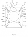
- FIG. 2 schematically shows an example in which the drum assembly 106 is connected to the body portion 104 by at least one biasing element.
- the drum assembly 106 is suspended from the body portion 104 by two biasing elements, namely first biasing element 124 and second biasing element 125.
- first biasing element 124 and second biasing element 125 may be used.
- Each biasing element 124, 125 may be a type of mechanical device that can absorb shock, such as a helical spring.
- first biasing element 124 is attached to the body portion 104, and the other end of the first biasing element 124 is attached to a part of the drum assembly 106, e.g. to the top of the drum housing 108.
- This configuration lets the first biasing element 124 dampen movement of the drum assembly 106 relative to the body portion 104 as the drum assembly 106 moves in response to the drum 110 being spun during a spin cycle.
- the second biasing element 125 is similarly connected to drum assembly 106.
- the drum assembly 106 may also be held by other types of supports.
- the drum assembly 106 is also supported by one or more dampers, in this example a first damper 126 and a second damper 127.
- a single damper 126 may be provided.
- one end of the first damper 126 is attached to the body portion 104, and the other end of the first damper 126 is attached to a part of the drum assembly 106, e.g. to the bottom of the drum housing 108.
- This configuration lets the first damper 126 dampen movement of the drum assembly 106 relative to the body portion 104 as the drum assembly 106 moves in response to the drum 110 being spun during a spin cycle.
- the second damper 127 is similarly connected to drum assembly 106.
- the washing machine 102 includes an example of an arrangement 128 that is constructed and arranged to cause an indication to be provided to a user in response to a biasing element of the washing machine 102 stretching beyond a predetermined threshold length. Stretching beyond a predetermined threshold length may also encompass failure of the biasing element e.g. snapping of the biasing element. In the example of Figure 2 this could be one or more of the first and second biasing elements 124, 125 each stretching beyond a predetermined threshold length. Of course, in an example comprising a single biasing element 124, then this could be the single biasing element 124 stretching beyond a predetermined length. Likewise, where there are three or more biasing elements then this could be any one or more of the three or more biasing elements stretching beyond a predetermined length.
- the arrangement 128 is constructed and arranged to physically engage with the first and second biasing elements 124,125. Therefore, movement of the first and second biasing elements 124, 125 may also effect movement of part of the arrangement 128. According to some examples movement of the first and second biasing elements 124, 125 beyond a predetermined amount will effect movement of the arrangement 128.
- the arrangement 128 may include one or more wires or one or more cables.
- the arrangement 128 includes a cable 130.
- the arrangement 128 may include a plurality of wires or a plurality of cables connected together.
- the arrangement 128 may include a plurality of linkages.
- the cable 130 has a first end 131 and a second end 133.
- the first end 131 of the cable 130 is anchored to a first component of the washing machine 102.
- the first end 131 of the cable 130 may be fixed to any suitable component of the washing machine 102.
- the first component is an anchor point 132 provided on the body portion 104.
- the first component is a part of the drum assembly 106, e.g. an anchor point provided on the drum housing 108.
- the first component is a biasing element, such as the first biasing element 124 or the second biasing element 125.
- the second end 133 of the cable 130 is attached to a second component of the washing machine 102.
- the second component may be a circuit breaker 134.
- the second component is a circuit breaker 134 provided in the door lock 116.
- the second component may be a different component of the door lock 116.
- the second component may be a different component of the door 114.
- the circuit breaker 134 may include a mechanical part such as a pin or a plug.
- a voltage can be supplied to the circuit breaker (e.g. 5V). When the pin is physically removed from a corresponding socket, the voltage is no longer sensed and the circuit breaker 134 is triggered.
- the cable 130 passes through an interior of the first and second biasing elements 124, 125. As one or more of the first and second biasing elements 124, 125 stretches beyond a predetermined length, the cable 130 is engaged or contacted by the extending biasing element 124 and/or 125 and the cable 130 is put under tension.
- the first and second biasing elements 124, 125 extend and contract during use of the washing machine 102 as they damp movement of the drum assembly 106 relative to the body portion 104. Therefore, although in this example the cable 130 is fixed to the anchor point 132 at one end and to the circuit breaker 134 at the other end, the cable 130 has a length that is sufficient to allow the biasing elements 124 to extend and contract normally, within a predetermined threshold range.
- the arrangement includes one or more pulleys 136, 137 for supporting the cable 130 above the drum assembly 106.
- the one or more pulleys 136, 137 are provided in order to maintain a sufficient level of tension in the cable 130, for example to prevent the cable 130 from contacting with the drum assembly 106.
- the one or more pulleys 136, 137 also facilitate movement of the cable 130 as the first and second biasing elements 124, 125 stretch.
- the one or more pulleys 136, 137 are attached to the body portion 104.
- a first pulley 136 is attached to the body portion 104 at a position that is the midpoint between the first and second biasing elements 124, 125.
- a second pulley 137 is attached to the body portion 103 at a position that is adjacent the second biasing element 125.
- the arrangement 128 is constructed and arranged to cause an indication to be provided to a user in response to at least one of the biasing elements 124, 125 stretching beyond a predetermined threshold length.
- both of the biasing elements 124 are being stretched to an extent that is within their operating limit and to a length that is below a predetermined threshold length.
- An edge 138 of the first biasing element 124 and an edge 140 of the second biasing element 125 are engaged with the cable 130.
- the cable 130 is also engaged with the first pulley 136 and the second pulley 137.
- This configuration transfers any force applied to each biasing element 124, which may be caused by the weight of the drum assembly 106, to the cable 130. Since one end of the cable 130 is fixed to the anchor point 132 and the other end of the cable is connected to the circuit breaker 134, the force applied to the cable 130 tensions the cable 130 and pulls it taut.
- each of the biasing elements 124, 125 is within their elastic limit, and the arrangement 128 is constructed and arranged such that the cable 130 is therefore not pulled to an extent that the cable 130 breaks the circuit breaker 134. That is, in some examples it may be considered there is still some slack in the cable 130.
- the cable 130 is put under increasing tension due to engagement with the biasing elements 124, 125.
- a biasing element stretches beyond a predetermined threshold limit such that it may become deformed, for example due to wear and tear
- the increased degree of tension that the cable 130 is put under causes the cable 130 to trigger the circuit breaker 134, as is shown in Figure 3 .
- the circuit breaker 134 is activated by the cable 130 pulling a pin 142 from a hole or socket of the circuit breaker 134.
- the length of the cable 130 is selected or calibrated so that the tension in the cable 130 does not trigger the circuit breaker 134 under normal operating conditions as the drum 110 spins within the drum housing 108.
- the cable 130 may have a degree of flex, which allows for expected movement of the drum assembly 106.
- an indication is provided to a user so that the user knows that one of the biasing elements 124 has stretched beyond its elastic limit and therefore that the drum assembly 106 may be imbalanced.
- the indication includes activating an alarm for alerting a user.
- the washing machine 102 includes an alarm 134. Additionally or alternatively, the washing machine 102 may be communicatively connected to an external alarm, for example over Wi-Fi or via a wired connection.
- the alarm 134 may include an audible alarm, such as a buzzer or a siren.
- the alarm 134 may include a haptic alarm (e.g. a tactile alarm) such as a vibration motor.
- the alarm 134 may include a visual alarm such as a warning message (e.g. "Imbalance Error") or warning light being displayed on the display 120.
- the alarm may include a warning message transmitted over a wireless connection to a user equipment (such as a user's mobile phone) for display on a display of the user equipment.
- the warning message may be transmitted over a shared Wi-Fi connection.
- the alarm may include two or more of an audible alarm, a haptic alarm and a visual alarm.
- the indication may include disabling the lock 116 (e.g. preventing locking of lock 116).
- the door lock 116 may be mechanically or electronically disabled from operating.
- the door lock 116 may be prevented from locking so that the user cannot lock the door 110 and therefore the user cannot use the washing machine 102.
- triggering the circuit breaker 134 physically prevents the door lock 116 from operating.
- the triggered circuit breaker 134 may block a first component of the door lock 116 (e.g. a catch) in order to stop the first component of the door lock 116 from being able to engage with a second component of the door lock 116 (e.g. a slot).
- the controller 122 is configured to control the provision of the indication to the user in response to one of the first and second biasing elements 124, 125 being stretched beyond a predetermined threshold length.
- the controller 122 receives an input from the circuit breaker 134 indicating that the circuit breaker 134 has been triggered, the controller 122 causes the indication to be output to the user.
- An advantage of the described arrangement is that an indication will be output to a user when a biasing element suspending the drum assembly 106 from the body portion 104 mechanically fails or is no longer fit for proper use. In this situation, the drum assembly 106 may be imbalanced. The indication prompts the user to have the washing machine 102 repaired so that the broken biasing element can be replaced. This means that the washing machine 102 is maintained to continue operating at a high performance level and ensures that user safety is not compromised.
- processor or processing system or circuitry referred to herein may in practice be provided by a single chip or integrated circuit or plural chips or integrated circuits, optionally provided as a chipset, an application-specific integrated circuit (ASIC), field-programmable gate array (FPGA), digital signal processor (DSP), graphics processing units (GPUs), etc.
- the chip or chips may comprise circuitry (as well as possibly firmware) for embodying at least one or more of a data processor or processors, a digital signal processor or processors, baseband circuitry and radio frequency circuitry, which are configurable so as to operate in accordance with the exemplary embodiments.
- the exemplary embodiments may be implemented at least in part by computer software stored in (non-transitory) memory and executable by the processor, or by hardware, or by a combination of tangibly stored software and hardware (and tangibly stored firmware).
- the invention also extends to computer programs, particularly computer programs on or in a carrier, adapted for putting the invention into practice.
- the program may be in the form of non-transitory source code, object code, a code intermediate source and object code such as in partially compiled form, or in any other non-transitory form suitable for use in the implementation of processes according to the invention.
- the carrier may be any entity or device capable of carrying the program.
- the carrier may comprise a storage medium, such as a solid-state drive (SSD) or other semiconductor-based RAM; a ROM, for example a CD ROM or a semiconductor ROM; a magnetic recording medium, for example a floppy disk or hard disk; optical memory devices in general; etc.
- SSD solid-state drive
- ROM read-only memory
- magnetic recording medium for example a floppy disk or hard disk
- optical memory devices in general etc.
Landscapes
- Engineering & Computer Science (AREA)
- Textile Engineering (AREA)
- Control Of Washing Machine And Dryer (AREA)
- Main Body Construction Of Washing Machines And Laundry Dryers (AREA)
Claims (9)
- Wasch- und/oder Trocknungsmaschine (102), aufweisend:ein Gehäuseteil (104);eine Trommelbaugruppe (106);ein Vorspannelement (124), das die Trommelbaugruppe (106) vom Gehäuseteil (104) aufhängt;dadurch gekennzeichnet, dass die Wasch- und/oder Trocknungsmaschine (102) aufweist:ein oder mehr Drähte oder Kabel (130), die konstruiert und angeordnet sind, um mit dem Vorspannelement (124) physisch in Eingriff zu stehen, sodass eine Bewegung des Vorspannelements (124) eine entsprechende Bewegung der ein oder mehr Drähte oder Kabel (130) bewirkt, wobei ein erstes Ende (131) der ein oder mehr Drähte oder Kabel (130) an einer ersten Komponente der Wasch- und/oder Trocknungsmaschine befestigt ist und ein zweites Ende (133) der ein oder mehr Drähte oder Kabel an einer Komponente eines Türschlosses (116) einer Tür (114) der Wasch- und/oder Trocknungsmaschine (102) angebracht ist;wobei die Wasch- und/oder Trocknungsmaschine (102) konstruiert und angeordnet ist, um ein Blockieren des Schließens der Tür (114) der Wasch- und/oder Trocknungsmaschine (102) als Reaktion darauf, dass sich das Vorspannelement (124) über eine vorbestimmte Schwellenlänge hinaus ausdehnt, zu veranlassen.
- Wasch- und/oder Trocknungsmaschine (102) nach Anspruch 1, aufweisend ein oder mehr Riemenscheiben (136, 137) zum Unterstützen der Bewegung der ein oder mehr Drähte oder Kabel (130).
- Wasch- und/oder Trocknungsmaschine (102) nach Anspruch 2, wobei die ein oder mehr Riemenscheiben (136, 137) am Gehäuseteil (104) befestigt sind.
- Wasch- und/oder Trocknungsmaschine (102) nach einem der vorhergehenden Ansprüche, wobei die erste Komponente eines aufweist von: dem Gehäuseteil (104); dem Vorspannelement (124); der Trommelbaugruppe (106).
- Wasch- und/oder Trocknungsmaschine (102) nach einem der vorhergehenden Ansprüche, wobei die Komponente des Türschlosses (116) einen Leistungsschalter (134) aufweist.
- Wasch- und/oder Trocknungsmaschine (102) nach einem der vorhergehenden Ansprüche, wobei das Vorspannelement (124) eine Schraubenfeder ist und die ein oder mehr Drähte oder Kabel (130) durch ein Inneres der Schraubenfeder verlaufen.
- Wasch- und/oder Trocknungsmaschine (102) nach einem der vorhergehenden Ansprüche, die konfiguriert ist, um einen Alarm als Reaktion darauf, dass sich das Vorspannelement (124) über die vorbestimmte Schwellenlänge hinaus ausdehnt, zu aktivieren.
- Wasch- und/oder Trocknungsmaschine (102) nach Anspruch 7, wobei der Alarm ein oder mehr aufweist von: einem akustischen Alarm; einem haptischen Alarm; einem visuellen Alarm.
- Wasch- und/oder Trocknungsmaschine (102) nach einem der vorhergehenden Ansprüche, wobei das Vorspannelement (124) ein erstes Vorspannelement (124) und ein zweites Vorspannelement (125) aufweist.
Priority Applications (1)
| Application Number | Priority Date | Filing Date | Title |
|---|---|---|---|
| EP19165606.5A EP3715523B1 (de) | 2019-03-27 | 2019-03-27 | Wasch- und/oder trocknungsmaschine |
Applications Claiming Priority (1)
| Application Number | Priority Date | Filing Date | Title |
|---|---|---|---|
| EP19165606.5A EP3715523B1 (de) | 2019-03-27 | 2019-03-27 | Wasch- und/oder trocknungsmaschine |
Publications (2)
| Publication Number | Publication Date |
|---|---|
| EP3715523A1 EP3715523A1 (de) | 2020-09-30 |
| EP3715523B1 true EP3715523B1 (de) | 2023-09-06 |
Family
ID=65995592
Family Applications (1)
| Application Number | Title | Priority Date | Filing Date |
|---|---|---|---|
| EP19165606.5A Active EP3715523B1 (de) | 2019-03-27 | 2019-03-27 | Wasch- und/oder trocknungsmaschine |
Country Status (1)
| Country | Link |
|---|---|
| EP (1) | EP3715523B1 (de) |
Family Cites Families (4)
| Publication number | Priority date | Publication date | Assignee | Title |
|---|---|---|---|---|
| DE3838998A1 (de) * | 1988-11-18 | 1990-05-23 | Licentia Gmbh | Beladungsmengenanzeige, insbesondere bei haushaltwaschmaschinen |
| JPH09140990A (ja) * | 1995-11-17 | 1997-06-03 | Sanyo Electric Co Ltd | ドラム式洗濯機 |
| KR101629673B1 (ko) * | 2009-11-16 | 2016-06-13 | 삼성전자 주식회사 | 세탁기 및 이의 포량감지장치 |
| KR101658226B1 (ko) * | 2009-11-16 | 2016-09-21 | 삼성전자주식회사 | 세탁기 및 그 제어방법 |
-
2019
- 2019-03-27 EP EP19165606.5A patent/EP3715523B1/de active Active
Also Published As
| Publication number | Publication date |
|---|---|
| EP3715523A1 (de) | 2020-09-30 |
Similar Documents
| Publication | Publication Date | Title |
|---|---|---|
| CN102137966B (zh) | 洗衣机 | |
| JP5753243B2 (ja) | 洗濯装置及び洗濯装置の制御方法 | |
| JP5010431B2 (ja) | 洗濯機 | |
| CN109477277B (zh) | 洗涤物处理器具 | |
| KR20160015889A (ko) | 의류 처리장치 | |
| JP5297934B2 (ja) | 洗濯機 | |
| US3504777A (en) | Combined unbalance and lid switch | |
| MX2010010369A (es) | Control de vibracion de dispositivo de lavado de ropa. | |
| EP2746452A1 (de) | Gefrierschutzverfahren für Waschmaschine | |
| KR20100116325A (ko) | 세탁장치 | |
| EP3715523B1 (de) | Wasch- und/oder trocknungsmaschine | |
| US7039976B2 (en) | Braking control system for a washing machine | |
| US20070227199A1 (en) | Laundry processing | |
| RU2589475C2 (ru) | Бытовой прибор для обработки белья и способ определения аварийного состояния устройства упругой подвески в бытовом приборе | |
| CA2336258C (en) | Washing machine with unbalance detection and control system | |
| WO2020108431A1 (zh) | 脱水机 | |
| US6477866B1 (en) | Washing machine motor cut-off | |
| KR20170086208A (ko) | 세탁물 처리기기 및 그 제어방법 | |
| CN105442247A (zh) | 使用用于水位和旋转失衡的集成传感设备的洗衣机和方法 | |
| KR101144785B1 (ko) | 드럼세탁기 | |
| JP6063851B2 (ja) | 洗濯機 | |
| KR102436702B1 (ko) | 탑로딩 세탁기 및 그에 따른 제어방법 | |
| KR102741874B1 (ko) | 세탁기 및 그 제어방법 | |
| KR101221892B1 (ko) | 탈수기의 탈수 제어 방법 및 그 탈수기 | |
| JP2025095481A (ja) | 洗濯機 |
Legal Events
| Date | Code | Title | Description |
|---|---|---|---|
| PUAI | Public reference made under article 153(3) epc to a published international application that has entered the european phase |
Free format text: ORIGINAL CODE: 0009012 |
|
| STAA | Information on the status of an ep patent application or granted ep patent |
Free format text: STATUS: THE APPLICATION HAS BEEN PUBLISHED |
|
| AK | Designated contracting states |
Kind code of ref document: A1 Designated state(s): AL AT BE BG CH CY CZ DE DK EE ES FI FR GB GR HR HU IE IS IT LI LT LU LV MC MK MT NL NO PL PT RO RS SE SI SK SM TR |
|
| AX | Request for extension of the european patent |
Extension state: BA ME |
|
| STAA | Information on the status of an ep patent application or granted ep patent |
Free format text: STATUS: REQUEST FOR EXAMINATION WAS MADE |
|
| 17P | Request for examination filed |
Effective date: 20210310 |
|
| RBV | Designated contracting states (corrected) |
Designated state(s): AL AT BE BG CH CY CZ DE DK EE ES FI FR GB GR HR HU IE IS IT LI LT LU LV MC MK MT NL NO PL PT RO RS SE SI SK SM TR |
|
| GRAP | Despatch of communication of intention to grant a patent |
Free format text: ORIGINAL CODE: EPIDOSNIGR1 |
|
| STAA | Information on the status of an ep patent application or granted ep patent |
Free format text: STATUS: GRANT OF PATENT IS INTENDED |
|
| INTG | Intention to grant announced |
Effective date: 20230324 |
|
| GRAS | Grant fee paid |
Free format text: ORIGINAL CODE: EPIDOSNIGR3 |
|
| GRAA | (expected) grant |
Free format text: ORIGINAL CODE: 0009210 |
|
| STAA | Information on the status of an ep patent application or granted ep patent |
Free format text: STATUS: THE PATENT HAS BEEN GRANTED |
|
| AK | Designated contracting states |
Kind code of ref document: B1 Designated state(s): AL AT BE BG CH CY CZ DE DK EE ES FI FR GB GR HR HU IE IS IT LI LT LU LV MC MK MT NL NO PL PT RO RS SE SI SK SM TR |
|
| REG | Reference to a national code |
Ref country code: GB Ref legal event code: FG4D |
|
| REG | Reference to a national code |
Ref country code: CH Ref legal event code: EP |
|
| REG | Reference to a national code |
Ref country code: IE Ref legal event code: FG4D |
|
| REG | Reference to a national code |
Ref country code: DE Ref legal event code: R096 Ref document number: 602019036572 Country of ref document: DE |
|
| REG | Reference to a national code |
Ref country code: LT Ref legal event code: MG9D |
|
| REG | Reference to a national code |
Ref country code: NL Ref legal event code: MP Effective date: 20230906 |
|
| PG25 | Lapsed in a contracting state [announced via postgrant information from national office to epo] |
Ref country code: GR Free format text: LAPSE BECAUSE OF FAILURE TO SUBMIT A TRANSLATION OF THE DESCRIPTION OR TO PAY THE FEE WITHIN THE PRESCRIBED TIME-LIMIT Effective date: 20231207 |
|
| PG25 | Lapsed in a contracting state [announced via postgrant information from national office to epo] |
Ref country code: SE Free format text: LAPSE BECAUSE OF FAILURE TO SUBMIT A TRANSLATION OF THE DESCRIPTION OR TO PAY THE FEE WITHIN THE PRESCRIBED TIME-LIMIT Effective date: 20230906 Ref country code: RS Free format text: LAPSE BECAUSE OF FAILURE TO SUBMIT A TRANSLATION OF THE DESCRIPTION OR TO PAY THE FEE WITHIN THE PRESCRIBED TIME-LIMIT Effective date: 20230906 Ref country code: NO Free format text: LAPSE BECAUSE OF FAILURE TO SUBMIT A TRANSLATION OF THE DESCRIPTION OR TO PAY THE FEE WITHIN THE PRESCRIBED TIME-LIMIT Effective date: 20231206 Ref country code: LV Free format text: LAPSE BECAUSE OF FAILURE TO SUBMIT A TRANSLATION OF THE DESCRIPTION OR TO PAY THE FEE WITHIN THE PRESCRIBED TIME-LIMIT Effective date: 20230906 Ref country code: LT Free format text: LAPSE BECAUSE OF FAILURE TO SUBMIT A TRANSLATION OF THE DESCRIPTION OR TO PAY THE FEE WITHIN THE PRESCRIBED TIME-LIMIT Effective date: 20230906 Ref country code: HR Free format text: LAPSE BECAUSE OF FAILURE TO SUBMIT A TRANSLATION OF THE DESCRIPTION OR TO PAY THE FEE WITHIN THE PRESCRIBED TIME-LIMIT Effective date: 20230906 Ref country code: GR Free format text: LAPSE BECAUSE OF FAILURE TO SUBMIT A TRANSLATION OF THE DESCRIPTION OR TO PAY THE FEE WITHIN THE PRESCRIBED TIME-LIMIT Effective date: 20231207 Ref country code: FI Free format text: LAPSE BECAUSE OF FAILURE TO SUBMIT A TRANSLATION OF THE DESCRIPTION OR TO PAY THE FEE WITHIN THE PRESCRIBED TIME-LIMIT Effective date: 20230906 |
|
| REG | Reference to a national code |
Ref country code: AT Ref legal event code: MK05 Ref document number: 1608695 Country of ref document: AT Kind code of ref document: T Effective date: 20230906 |
|
| PG25 | Lapsed in a contracting state [announced via postgrant information from national office to epo] |
Ref country code: NL Free format text: LAPSE BECAUSE OF FAILURE TO SUBMIT A TRANSLATION OF THE DESCRIPTION OR TO PAY THE FEE WITHIN THE PRESCRIBED TIME-LIMIT Effective date: 20230906 |
|
| PG25 | Lapsed in a contracting state [announced via postgrant information from national office to epo] |
Ref country code: IS Free format text: LAPSE BECAUSE OF FAILURE TO SUBMIT A TRANSLATION OF THE DESCRIPTION OR TO PAY THE FEE WITHIN THE PRESCRIBED TIME-LIMIT Effective date: 20240106 |
|
| PG25 | Lapsed in a contracting state [announced via postgrant information from national office to epo] |
Ref country code: AT Free format text: LAPSE BECAUSE OF FAILURE TO SUBMIT A TRANSLATION OF THE DESCRIPTION OR TO PAY THE FEE WITHIN THE PRESCRIBED TIME-LIMIT Effective date: 20230906 |
|
| PG25 | Lapsed in a contracting state [announced via postgrant information from national office to epo] |
Ref country code: ES Free format text: LAPSE BECAUSE OF FAILURE TO SUBMIT A TRANSLATION OF THE DESCRIPTION OR TO PAY THE FEE WITHIN THE PRESCRIBED TIME-LIMIT Effective date: 20230906 |
|
| PG25 | Lapsed in a contracting state [announced via postgrant information from national office to epo] |
Ref country code: SM Free format text: LAPSE BECAUSE OF FAILURE TO SUBMIT A TRANSLATION OF THE DESCRIPTION OR TO PAY THE FEE WITHIN THE PRESCRIBED TIME-LIMIT Effective date: 20230906 Ref country code: RO Free format text: LAPSE BECAUSE OF FAILURE TO SUBMIT A TRANSLATION OF THE DESCRIPTION OR TO PAY THE FEE WITHIN THE PRESCRIBED TIME-LIMIT Effective date: 20230906 Ref country code: IS Free format text: LAPSE BECAUSE OF FAILURE TO SUBMIT A TRANSLATION OF THE DESCRIPTION OR TO PAY THE FEE WITHIN THE PRESCRIBED TIME-LIMIT Effective date: 20240106 Ref country code: ES Free format text: LAPSE BECAUSE OF FAILURE TO SUBMIT A TRANSLATION OF THE DESCRIPTION OR TO PAY THE FEE WITHIN THE PRESCRIBED TIME-LIMIT Effective date: 20230906 Ref country code: EE Free format text: LAPSE BECAUSE OF FAILURE TO SUBMIT A TRANSLATION OF THE DESCRIPTION OR TO PAY THE FEE WITHIN THE PRESCRIBED TIME-LIMIT Effective date: 20230906 Ref country code: CZ Free format text: LAPSE BECAUSE OF FAILURE TO SUBMIT A TRANSLATION OF THE DESCRIPTION OR TO PAY THE FEE WITHIN THE PRESCRIBED TIME-LIMIT Effective date: 20230906 Ref country code: AT Free format text: LAPSE BECAUSE OF FAILURE TO SUBMIT A TRANSLATION OF THE DESCRIPTION OR TO PAY THE FEE WITHIN THE PRESCRIBED TIME-LIMIT Effective date: 20230906 Ref country code: PT Free format text: LAPSE BECAUSE OF FAILURE TO SUBMIT A TRANSLATION OF THE DESCRIPTION OR TO PAY THE FEE WITHIN THE PRESCRIBED TIME-LIMIT Effective date: 20240108 Ref country code: SK Free format text: LAPSE BECAUSE OF FAILURE TO SUBMIT A TRANSLATION OF THE DESCRIPTION OR TO PAY THE FEE WITHIN THE PRESCRIBED TIME-LIMIT Effective date: 20230906 |
|
| PG25 | Lapsed in a contracting state [announced via postgrant information from national office to epo] |
Ref country code: PL Free format text: LAPSE BECAUSE OF FAILURE TO SUBMIT A TRANSLATION OF THE DESCRIPTION OR TO PAY THE FEE WITHIN THE PRESCRIBED TIME-LIMIT Effective date: 20230906 Ref country code: IT Free format text: LAPSE BECAUSE OF FAILURE TO SUBMIT A TRANSLATION OF THE DESCRIPTION OR TO PAY THE FEE WITHIN THE PRESCRIBED TIME-LIMIT Effective date: 20230906 |
|
| REG | Reference to a national code |
Ref country code: DE Ref legal event code: R097 Ref document number: 602019036572 Country of ref document: DE |
|
| PG25 | Lapsed in a contracting state [announced via postgrant information from national office to epo] |
Ref country code: DK Free format text: LAPSE BECAUSE OF FAILURE TO SUBMIT A TRANSLATION OF THE DESCRIPTION OR TO PAY THE FEE WITHIN THE PRESCRIBED TIME-LIMIT Effective date: 20230906 |
|
| PLBE | No opposition filed within time limit |
Free format text: ORIGINAL CODE: 0009261 |
|
| STAA | Information on the status of an ep patent application or granted ep patent |
Free format text: STATUS: NO OPPOSITION FILED WITHIN TIME LIMIT |
|
| PG25 | Lapsed in a contracting state [announced via postgrant information from national office to epo] |
Ref country code: DK Free format text: LAPSE BECAUSE OF FAILURE TO SUBMIT A TRANSLATION OF THE DESCRIPTION OR TO PAY THE FEE WITHIN THE PRESCRIBED TIME-LIMIT Effective date: 20230906 Ref country code: SI Free format text: LAPSE BECAUSE OF FAILURE TO SUBMIT A TRANSLATION OF THE DESCRIPTION OR TO PAY THE FEE WITHIN THE PRESCRIBED TIME-LIMIT Effective date: 20230906 |
|
| 26N | No opposition filed |
Effective date: 20240607 |
|
| REG | Reference to a national code |
Ref country code: DE Ref legal event code: R119 Ref document number: 602019036572 Country of ref document: DE |
|
| REG | Reference to a national code |
Ref country code: CH Ref legal event code: PL |
|
| PG25 | Lapsed in a contracting state [announced via postgrant information from national office to epo] |
Ref country code: BG Free format text: LAPSE BECAUSE OF FAILURE TO SUBMIT A TRANSLATION OF THE DESCRIPTION OR TO PAY THE FEE WITHIN THE PRESCRIBED TIME-LIMIT Effective date: 20230906 |
|
| PG25 | Lapsed in a contracting state [announced via postgrant information from national office to epo] |
Ref country code: LU Free format text: LAPSE BECAUSE OF NON-PAYMENT OF DUE FEES Effective date: 20240327 |
|
| PG25 | Lapsed in a contracting state [announced via postgrant information from national office to epo] |
Ref country code: MC Free format text: LAPSE BECAUSE OF FAILURE TO SUBMIT A TRANSLATION OF THE DESCRIPTION OR TO PAY THE FEE WITHIN THE PRESCRIBED TIME-LIMIT Effective date: 20230906 |
|
| GBPC | Gb: european patent ceased through non-payment of renewal fee |
Effective date: 20240327 |
|
| PG25 | Lapsed in a contracting state [announced via postgrant information from national office to epo] |
Ref country code: MC Free format text: LAPSE BECAUSE OF FAILURE TO SUBMIT A TRANSLATION OF THE DESCRIPTION OR TO PAY THE FEE WITHIN THE PRESCRIBED TIME-LIMIT Effective date: 20230906 Ref country code: LU Free format text: LAPSE BECAUSE OF NON-PAYMENT OF DUE FEES Effective date: 20240327 Ref country code: BG Free format text: LAPSE BECAUSE OF FAILURE TO SUBMIT A TRANSLATION OF THE DESCRIPTION OR TO PAY THE FEE WITHIN THE PRESCRIBED TIME-LIMIT Effective date: 20230906 |
|
| REG | Reference to a national code |
Ref country code: BE Ref legal event code: MM Effective date: 20240331 |
|
| PG25 | Lapsed in a contracting state [announced via postgrant information from national office to epo] |
Ref country code: DE Free format text: LAPSE BECAUSE OF NON-PAYMENT OF DUE FEES Effective date: 20241001 |
|
| PG25 | Lapsed in a contracting state [announced via postgrant information from national office to epo] |
Ref country code: BE Free format text: LAPSE BECAUSE OF NON-PAYMENT OF DUE FEES Effective date: 20240331 |
|
| PG25 | Lapsed in a contracting state [announced via postgrant information from national office to epo] |
Ref country code: GB Free format text: LAPSE BECAUSE OF NON-PAYMENT OF DUE FEES Effective date: 20240327 |
|
| PG25 | Lapsed in a contracting state [announced via postgrant information from national office to epo] |
Ref country code: FR Free format text: LAPSE BECAUSE OF NON-PAYMENT OF DUE FEES Effective date: 20240331 |
|
| PG25 | Lapsed in a contracting state [announced via postgrant information from national office to epo] |
Ref country code: IE Free format text: LAPSE BECAUSE OF NON-PAYMENT OF DUE FEES Effective date: 20240327 |
|
| PG25 | Lapsed in a contracting state [announced via postgrant information from national office to epo] |
Ref country code: IE Free format text: LAPSE BECAUSE OF NON-PAYMENT OF DUE FEES Effective date: 20240327 Ref country code: GB Free format text: LAPSE BECAUSE OF NON-PAYMENT OF DUE FEES Effective date: 20240327 Ref country code: FR Free format text: LAPSE BECAUSE OF NON-PAYMENT OF DUE FEES Effective date: 20240331 Ref country code: DE Free format text: LAPSE BECAUSE OF NON-PAYMENT OF DUE FEES Effective date: 20241001 Ref country code: BE Free format text: LAPSE BECAUSE OF NON-PAYMENT OF DUE FEES Effective date: 20240331 Ref country code: CH Free format text: LAPSE BECAUSE OF NON-PAYMENT OF DUE FEES Effective date: 20240331 |
|
| PGFP | Annual fee paid to national office [announced via postgrant information from national office to epo] |
Ref country code: TR Payment date: 20250326 Year of fee payment: 7 |
|
| PG25 | Lapsed in a contracting state [announced via postgrant information from national office to epo] |
Ref country code: CY Free format text: LAPSE BECAUSE OF FAILURE TO SUBMIT A TRANSLATION OF THE DESCRIPTION OR TO PAY THE FEE WITHIN THE PRESCRIBED TIME-LIMIT; INVALID AB INITIO Effective date: 20190327 |
|
| PG25 | Lapsed in a contracting state [announced via postgrant information from national office to epo] |
Ref country code: HU Free format text: LAPSE BECAUSE OF FAILURE TO SUBMIT A TRANSLATION OF THE DESCRIPTION OR TO PAY THE FEE WITHIN THE PRESCRIBED TIME-LIMIT; INVALID AB INITIO Effective date: 20190327 |