EP3715567B1 - Unité de verrouillage pour portes et fenêtres - Google Patents
Unité de verrouillage pour portes et fenêtres Download PDFInfo
- Publication number
- EP3715567B1 EP3715567B1 EP20165197.3A EP20165197A EP3715567B1 EP 3715567 B1 EP3715567 B1 EP 3715567B1 EP 20165197 A EP20165197 A EP 20165197A EP 3715567 B1 EP3715567 B1 EP 3715567B1
- Authority
- EP
- European Patent Office
- Prior art keywords
- lock unit
- rotation
- drive member
- unit according
- cylinder
- Prior art date
- Legal status (The legal status is an assumption and is not a legal conclusion. Google has not performed a legal analysis and makes no representation as to the accuracy of the status listed.)
- Active
Links
Images



Classifications
-
- E—FIXED CONSTRUCTIONS
- E05—LOCKS; KEYS; WINDOW OR DOOR FITTINGS; SAFES
- E05C—BOLTS OR FASTENING DEVICES FOR WINGS, SPECIALLY FOR DOORS OR WINDOWS
- E05C9/00—Arrangements of simultaneously actuated bolts or other securing devices at well-separated positions on the same wing
- E05C9/04—Arrangements of simultaneously actuated bolts or other securing devices at well-separated positions on the same wing with two sliding bars moved in opposite directions when fastening or unfastening
- E05C9/041—Arrangements of simultaneously actuated bolts or other securing devices at well-separated positions on the same wing with two sliding bars moved in opposite directions when fastening or unfastening with rack and pinion mechanism
-
- E—FIXED CONSTRUCTIONS
- E05—LOCKS; KEYS; WINDOW OR DOOR FITTINGS; SAFES
- E05B—LOCKS; ACCESSORIES THEREFOR; HANDCUFFS
- E05B13/00—Devices preventing the key or the handle or both from being used
- E05B13/002—Devices preventing the key or the handle or both from being used locking the handle
- E05B13/004—Devices preventing the key or the handle or both from being used locking the handle by locking the spindle, follower, or the like
-
- E—FIXED CONSTRUCTIONS
- E05—LOCKS; KEYS; WINDOW OR DOOR FITTINGS; SAFES
- E05B—LOCKS; ACCESSORIES THEREFOR; HANDCUFFS
- E05B63/00—Locks or fastenings with special structural characteristics
- E05B63/0017—Locks with sliding bolt without provision for latching
- E05B63/0021—Locks with sliding bolt without provision for latching the bolt being shot over an increased length by a single turning operation of the key
-
- E—FIXED CONSTRUCTIONS
- E05—LOCKS; KEYS; WINDOW OR DOOR FITTINGS; SAFES
- E05B—LOCKS; ACCESSORIES THEREFOR; HANDCUFFS
- E05B63/00—Locks or fastenings with special structural characteristics
- E05B63/18—Locks or fastenings with special structural characteristics with arrangements independent of the locking mechanism for retaining the bolt or latch in the retracted position
Definitions
- the present invention relates to a lock unit for closing elements in general, such as roller shutters, up-and-over doors, security grills, gates and other doors and windows.
- Locks for doors and windows are known that enable, for example, a roller shutter, or an up-and-over door or a security grill or a gate or the like to be opened and closed by acting on appropriate handles coupled therewith.
- a known lock for example for a security grill, in addition to the manually drivable handle, also comprises a cylinder, which is drivable by a dedicated key, for immobilizing, i.e. key locking, the grill in the locked position.
- a lock of this type generally comprises internally a transmission mechanism that enables the movement of the handle to be transferred to the bolts, which are slidable respectively in a zone placed above and in a zone placed below the lock, in the case of a grill.
- the transmission mechanism transforms a rotation of the handle in a linear movement, in mutually opposite directions, of the two bolts that in such a manner can engage with an upper engaging seat and a lower engaging seat, obtained on the opposite stationary upper and lower crosspieces, of the counterframe of the door or window.
- the user When key locking of the grill is required, the user has to bring the grill up to the counterframe, rotate the handle to the locked position, and drive, by the respective key, the cylinder to a first angular key locking position.
- the handle remains immobilized, preventing accidental opening of the grill both from the inside and the outside (in the case of the presence of handles on both sides) thus preventing any undesired intrusion from the outside.
- the user In order to release the security grill, the user has to act, by the key, to rotate the cylinder to a second angular release position. After key unlocking, the handle can be freely rotated in one or the other direction, to close or open the grill, without obviously key locking it.
- One limit of this lock is that, in certain circumstances, the possibility of rotating the handle freely to close or open the grill, without being in possession of the key for the cylinder, can lead to undesired situations.
- the key is generally in the hands of the caretaker looking after the facility who, in the normal course of sporting activities may not necessarily be near the changing rooms but be elsewhere to perform other duties or tasks. Also in this case, an individual, acting innocently, or worse, with ill intent, although not possessing the key, would have the possibility of locking the grill by acting only on the handle, blocking the user players on the pitch and preventing the user-players from accessing the changing rooms.
- roller shutter can be raised and lowered by driving a suitable motor with which the roller shutter is fitted.
- the roller shutter is immobilized in the locked position by acting manually on a handle with which a key lock cylinder is also coupled.
- the operations of installing a grill or a roller shutter, or another closing element may not be performed correctly, or may be difficult because of the particular conformation of the walls on which to install the door or window, this resulting in assembly precision levels that are hardly satisfactory.
- the movable closing element the door or grill etc
- counterframe or portion of masonry counterframe or portion of masonry
- the projecting stroke of the bolts could be insufficient to achieve engagement with the respective locking seats, or at least, whilst reaching these seats, the required degree of penetration and engagement in the seats would not be ensured, the security requirement of the window or door being thus prejudged.
- EP1321613 discloses lock device, particularly for shutters.
- FR2423610 discloses a casement lock for French windows.
- the object of the present invention is to improve currently used locks. Another object of the present invention is to provide a new and different solution for a lock that is able to overcome the aforementioned limits and drawbacks.
- one object is to provide a lock unit that is so configured as to prevent the undesired situations referred to above. More precisely, the intention is to provide a technical solution by means of which the user of the lock unit always has the certainty and security that the lock unit is and remains in the operating state (key locked position, unlocked position) set by the user by the key, preventing the handle associated therewith from being able to be rotated freely from one operating position to another position by a user who is not in the possession of the key.
- the object is thus to provide a lock unit configured in such a way that each change of position of the handle/s requires, to be actuated, preliminarily a corresponding enabling action that is achievable only by the aforesaid key.
- a further object is to provide a lock unit with increased levels of security, with particular reference to the projection stroke of the bolts that engage in the respective locking seats.
- a still further object is to provide a lock unit that despite having compact dimensions and being simplified from the constructional point of view enables high bolt excursion values to be provided to thus ensure increased levels of security in the action of shutting the doors and windows.
- the present invention thus aims to achieve the aforesaid objects and overcome the drawbacks of conventional locks for doors and windows by a solution according to claim 1.
- a lock unit for doors or windows comprising:
- a lock unit 1 is disclosed below that is suitable for being fitted to a door or window in general, such as a roller shutter, an openable security grill, a gate, an up-and-over door, a sectional door and other possible closing elements.
- the lock unit 1 is of the type comprising a cylinder C drivable by a respective key K, from the inside and/or the outside with respect to a room that is accessible through the door or window.
- a handle is couplable, for example only on the side inside the room, or also on the side of the door or window outside the room.
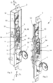
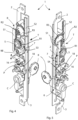
- the lock unit 1 comprises a box body 4 inside which the various mechanical components are enclosed.
- the lock unit 1 comprises a first drive member 2 and a second drive member 3 that are movable along respective projection directions D I , and along respective retraction directions D II for retracting with respect to the box body 4.
- the first drive member 2 and the second drive member 3 have, in particular, an elongated shape, more precisely a shaped bar shape, and are shaped to be connected to respective lock bolts, or bolts, that can be moved to engage with and disengage from, respective locking seats, provided on the masonry parts or on the fixed counterframe to which the door or window is fixed movably.
- the lock unit 1 is provided with a control element 5 suitable for coupling with a rotatable handle to move the aforesaid first member 2 and second drive member 3, and thus the respective bolts, in the projecting/retracting DI, DII directions.
- the projecting/retracting DI, DII directions are horizontal directions, whilst in the case of a gate, grill, or the like, the projecting/retracting DI, DII directions are vertical directions.
- the control element 5 in particular, is shaped with a toothed wheel part and another disk-shaped part and has centrally a hole of square section that is suitable for coupling with a square pin that is connectable to the handle/s.
- the lock unit 1 includes transmitting means T for transmitting a movement of the first member 2 and second member 3 to drive the bolts.
- the transmitting means T is configured for transforming rotation of the control element 5 into linear movement of the first member 2 and second drive member 3 in the aforesaid projecting/retracting (DI, DII) directions. Below, the transmitting means T will be disclosed in greater detail.
- the lock unit 1 comprises a seat 6 shaped for housing the lock cylinder C for key locking the lock unit 1.
- a control device (W) is provided that is activatable by the cylinder C and configured for enabling rotation of the handle/s in a first rotation direction only as far as the cylinder C is taken, by the respective key K, in a first angular position, on the other hand impeding, in this first angular position of the key K, rotation of the handle/s in a second rotation direction opposite the aforesaid first rotation direction.
- the control device W is configured for enabling rotation of the handle/s in the aforesaid second rotation direction only by as far as the lock cylinder C is taken, by the respective key K, in a second angular position, preventing, in this second angular position of the key K, the rotation of the handle in the first rotation direction.
- the control device W comprises a ratchet mechanism (7, 8, 9) configured for enabling/disabling rotation of the aforesaid control element 5 in function of the angular position in which the lock cylinder C is rotated.
- the control device W will be disclosed in greater detail below.
- the aforesaid transmitting means comprises toothed wheel means R and rack means S cooperating together to transmit movement from the control element 5 to the first member 2 and second drive member 3 (bar members shaped for the lock bolts) to move the bolts.
- the aforesaid toothed wheel means R comprises a first toothed wheel R1, which is integrally connected to or wholly obtained on, the aforesaid control element 5 that engages with a first rack S1 of the aforesaid rack means S.
- the first rack S1 engages with a second toothed wheel R2, coaxially connected integrally to a third wheel R3, or obtained completely, together with the latter, from a single piece.
- the third wheel R3 engages with a second rack S2 obtained on the second drive member 3 on which a third rack S3 is also obtained engaging with a fourth toothed wheel R4 that is coaxial and rotationally integral with the aforesaid wheel means R3 of the ratchet mechanism.
- the fourth toothed wheel R4 engages, on a side opposite the third rack S3, with a fourth rack S4 obtained on the first drive member 2, so that a linear movement of the second drive member 3 is matched by an identical movement, but in the opposite direction, of the first drive member 2.
- a rotation of the handle, and thus of the control element 5 to which the first wheel R is integrally connected causes movement of the first rack S1, which in turn rotates the second wheel R2.
- the third wheel R3, which is rotationally integral with the second wheel R2, moves the second rack S2 (obtained on the second drive member 3) in a direction opposite the movement of the first rack S1. Owing to a suitable and well-studied configuration of the wheels R1, R2, R3 the desired movement values of the first rack S1 and of the second rack S2 are obtained.
- amplification is advantageously obtained of the movement of the second rack S2 compared with the rotation of the control element 5.
- a small rotation of the handle is matched by a significant stroke of the drive member 2, and also, as is shown by the following description, of the drive member 3 in the opposite movement direction. This clearly translates into a significant projection stroke of the bolts in opposite directions.
- the movement of the second rack S2, i.e. of the second drive member 3, entails movement of the third rack S3 (fully obtained on the second drive member 3) which thus rotates the fourth wheel R4 which engages, on the diametrically opposite side, with the fourth rack S4 obtained on the first drive member 2. It is thus clear that a rotation of the fourth wheel R4 simultaneously moves by the same amount, but in opposite directions, the first drive member 2 and the second drive member 3.
- the transmitting means T are so configured that the first 2 and second drive members 3, and thus the respective bolts, have a projection stroke of at least 35 mm. In particular, in one embodiment, this stroke is equal to about 50 mm.
- This projection stroke which is noticeably greater than the usual approximately 25 mm of conventional locks, enables higher levels of security to be obtained, owing to a greater length of engagement of the bolts in the respective seats.
- lock unit 1 is provided by the particular configuration of the rack system S1, S2, S3, S4, in particular owing to the doubling of the first rack S1 with respect to the first drive member 2, which enables significantly reduced overall dimensions to be obtained, above all in the width of the box body 4, and a significant excursion of the bolts.
- control device W The aforementioned control device W is now disclosed in greater detail.
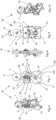
- the ratchet mechanism which is part of the aforesaid control device W, comprises a wheel 7 provided with toothed portions 8 and engaging lever means 9 configured for engaging with the toothed portions 8 to prevent a rotation of the wheel 7 in a determined rotation direction.
- the toothed portions 8 can affect, only extend along one or more arch portions of the circular edge of the wheel 7, or in an equivalent manner, can extend along the entire round angle of this peripheral circular edge of the wheel 7.
- the engaging lever means comprises a pair of lever elements 9A, 9B which are rotatable around the same axis A2 with respect to one another and are mutually connected by a return spring element 20.
- lever element 9A When the lever element 9A is engaged with a toothed portion 8, it exerts a blocking action on the wheel 7, preventing the latter from rotating in the first direction Z1 indicated in Figure 9 .
- the control device W comprises a rocker element 10, oscillating around an axis A1, which is rotatable by the bit element 12 of the cylinder C and configured for rotating the pair of engaging levers 9A, 9B in a determined rotation direction according to the rotation that is given with the key K, so as to prevent the rotation of the wheel 7 in the one or the other rotation direction.
- the rocker element 10 is provided with a driving end 11 shaped for selectively coming into contact with, and pushing, a first abutting surface 13 or a second abutting surface 14 each obtained on a respective engaging lever 9A, 9B.
- the driving end 11 alternatively comes into contact with the first abutting surface 13 or with the second abutting surface 14 in function of the rotation of the cylinder C, to prevent rotation of the wheel 7 in one or the other rotation direction.
- the rocker element 10 comprises a scissor-shaped activating end 15, having two protrusions 15A, 15B that are mutually spaced apart and arranged for receiving a thrust action from the bit element 12 of the cylinder C for rotation, respectively, in one direction or in the opposite direction.
- the control device W includes a locking slide element 16, slidable parallel to the aforesaid projecting/retracting DI, DII directions between a stop position, in which it is nearer to the cylinder C, and a release position, in which it is further from the cylinder C.
- the locking slide element 16 is configured for locking, when it is in the stop position, the ratchet mechanism 7, 8, 9 in the desired position, preventing a movement thereof, of accidental type or caused by break-in attempts, to a release position.
- a spring 19 is provided to recall the locking slide element 16 to the stop position.
- the locking slide element 16 comprises a thrust edge 17 that is suitable for receiving the thrust action from the bit element 12 of the cylinder C to reach the release position.
- a shaped slot 18 is obtained, inside which a peg P is received, projecting from the rocker element 10 orthogonally with respect to the projecting/retracting (DI, DII) directions.
- the slide element 16 comprises a locking protrusion B that extends in the slot 18 and is shaped for locking the peg P, and thus the rocker element 10, when the slide element 16 is in the aforesaid stop position.
- control device W The operation of the control device W is now disclosed, starting from an operating position in which the drive members 2 and 3 (and thus the bolts) are completely retracted. Considering the position shown in Figures 2 to 5 , a rotation of the handle to extract the bolts would be prevented by the blocking action that the engaging lever 9b exerts on the wheel 7, and as previously disclosed, is inserted into the sequence of transmission elements consisting of wheels and racks. This position of the control device W is also shown in Fig-ures 6 to 10 .
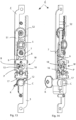
- the rotation of the handle must then be enabled by first rotating the cylinder C with the key K, such that the rocker element 10 moves to the other position (shown for example in figures 13 and 15 ).
- the bit element 12 first lifts the slide element 16, by disengaging the locking protrusion B from the peg P that is integral with the rocker element 10, and then coming into contact with the activation end 15A of the rocker element 10 by making the latter oscillate to the required position.
- the new technical solution according to the invention provides the user constantly with the certainty and security that the lock unit 1 is and remains in the key locked operating state or in the unlocked position that the user himself imposes by the key. Without the preliminary intervention only with the key, any change of angular position of the handle associated with the intervention is prevented.
- lock unit 1 fully meets specific needs of certain markets and/or preferences for use that certain users set.
Landscapes
- Engineering & Computer Science (AREA)
- Structural Engineering (AREA)
- Mechanical Engineering (AREA)
- Lock And Its Accessories (AREA)
Claims (14)
- Unité de serrure pour portes ou fenêtres, comprenant :- un premier élément d'entraînement (2) et un second élément d'entraînement (3) qui sont mobiles le long de directions respectives de projection/rétraction (DI, DII) par rapport à un corps de boîtier (4) de ladite unité de serrure (1), chacun dudit premier élément d'entraînement (2) et second élément d'entraînement (3) étant adaptés chacun pour être reliés à et déplacer un pêne respectif de manière à engager le pêne respectif avec et à dégager le pêne respectif d'un siège de verrouillage respectif prévu sur un mur ou sur un contre-châssis fixe,- un élément de commande (5) apte à être couplé à une poignée rotative pour déplacer lesdits premier élément d'entraînement (2) et second élément d'entraînement (3) dans lesdites directions de projection/rétraction (DI, D II),- des moyens de transmission (T) pour transmettre un déplacement dudit élément de commande (5) vers ledit premier élément (2) et un second élément (3) pour entraîner les pênes, lesdits moyens de transmission (T) étant configurés pour transformer une rotation de l'élément de commande (5) en un déplacement linéaire dudit premier élément d'entraînement (2) et dudit second élément d'entraînement (3) dans lesdites directions de projection/rétraction (DI, DII),- un siège (6) formé pour loger un barillet de serrure (C) pour verrouiller à clé ladite unité de serrure (1),- un dispositif de commande (W) qui peut être activé par ledit barillet de serrure (C) et configuré pour permettre la rotation de ladite poignée dans une première direction de rotation uniquement jusqu'à ce que ledit barillet de serrure (C) soit amené, par la clé respective (K), dans une première position angulaire, empêchant d'autre part, dans cette première position angulaire de la clé (K), la rotation de ladite poignée dans une deuxième direction de rotation opposée à ladite première direction de rotation,- ledit dispositif de commande (W) étant configuré pour permettre la rotation de ladite poignée dans ladite seconde direction de rotation uniquement jusqu'à ce que ledit barillet de serrure (C) soit amené, par la clé respective (K), à une seconde position angulaire, empêchant, dans cette seconde position angulaire de ladite clé (K), la rotation de ladite poignée dans la première direction de rotation.
- Unité de serrure selon la revendication 1, dans laquelle ledit dispositif de commande (W) comprend un mécanisme à rochet (7, 8, 9) configuré pour activer/désactiver la rotation dudit élément de commande (5) en fonction de la position angulaire dans laquelle ledit barillet de serrure (C) est tourné.
- Unité de serrure selon la revendication 2, dans laquelle ledit mécanisme à rochet comprend des moyens de roue (7) pourvus de parties dentées (8) et des moyens de levier de mise en prise (9) configurés pour venir en prise avec lesdites parties dentées (8) afin d'empêcher une rotation desdits moyens de roue (7) dans une direction de rotation déterminée.
- Unité de serrure selon la revendication 3, dans laquelle ledit dispositif de commande (W) comprend un élément basculant (10), oscillant autour d'un axe (A1), qui peut être entraîné en rotation par l'élément de panneton (12) dudit barillet (C) et configuré pour mettre en rotation lesdits moyens de levier de mise en prise (9) dans une direction de rotation déterminée en fonction de la rotation de ladite clé (K), de manière à empêcher la rotation desdits moyens de roue (7) dans une première direction ou dans l'autre direction de rotation.
- Unité de serrure selon la revendication 4, dans laquelle ledit élément basculant (10) est pourvu d'une extrémité d'entraînement (11) mise en forme pour venir sélectivement en contact avec, et pousser, une première surface de butée (13) ou une seconde surface de butée (14) desdits moyens de levier de mise en prise (9), en fonction de la rotation dudit barillet (C), pour empêcher la rotation desdits moyens de roue (7) dans une première ou dans l'autre direction de rotation.
- Unité de serrure selon la revendication 4 ou 5, dans laquelle ledit élément basculant (10) comprend une extrémité d'activation en forme de ciseaux (15), présentant deux protubérances (15A, 15B) qui sont mutuellement espacées et agencées pour recevoir une action de poussée à partir dudit élément de panneton (12) dudit barillet (C) pour tourner, respectivement, dans une première direction ou dans la direction de rotation opposée.
- Unité de serrure selon l'une quelconque des revendications 2 à 6, dans laquelle ledit dispositif de commande (W) inclut un élément coulissant de verrouillage (16), pouvant coulisser parallèlement auxdites directions de projection/rétraction (DI, DII) entre une position d'arrêt, dans laquelle il est plus proche dudit barillet (C), et une position de libération, dans laquelle il est plus éloigné dudit barillet (C), ledit élément coulissant de verrouillage (16) étant configuré pour verrouiller, lorsqu'il est dans la position d'arrêt, ledit mécanisme à rochet (7, 8, 9) dans la position souhaitée, en empêchant un déplacement de celui-ci, de type accidentel ou provoqué par des tentatives d'effraction, vers une position de libération, un ressort (19) étant prévu pour rappeler ledit élément coulissant de verrouillage (16) vers ladite position d'arrêt.
- Unité de serrure selon la revendication 7 telle qu'annexée à la revendication 4 ou 5, dans laquelle ledit élément coulissant de verrouillage (16) comprend un bord de poussée (17) qui est adapté pour recevoir l'action de poussée de l'élément de panneton (12) dudit barillet (C) pour atteindre ladite position de libération, et une fente profilée (18), à l'intérieur de laquelle un ergot (P) est reçu, faisant saillie à partir dudit élément basculant (10) orthogonalement par rapport auxdites directions de projection/rétraction (DI, DII), ledit élément coulissant (16) comprenant une protubérance de verrouillage (B) qui s'étend dans ladite fente (18) et est mis en forme pour verrouiller ledit ergot (P), et donc ledit élément basculant (10), lorsque ledit élément coulissant (16) est dans ladite position d'arrêt.
- Unité de verrouillage selon la revendication 3, ou selon l'une des revendications 4 à 8 telles qu'annexées directement ou indirectement à la revendication 3, dans laquelle lesdits moyens de levier de mise en prise (9) comprennent une paire d'éléments de levier (9A, 9B) qui peuvent tourner autour d'un même axe (A2) l'un par rapport à l'autre et sont mutuellement reliés par un élément de ressort de rappel (20).
- Unité de serrure selon une quelconque revendication précédente, dans laquelle lesdits moyens de transmission comprennent des moyens à roues dentées (R) et des moyens à crémaillères (S) qui coopèrent mutuellement pour transmettre le mouvement dudit élément de commande (5) audit premier élément (2) et second élément d'entraînement (3) pour les pênes.
- Unité de serrure selon la revendication 10, dans laquelle lesdits moyens à roues dentées (R) comprennent une première roue dentée (R1) reliée d'un seul tenant audit élément de commande (5), ladite première roue dentée (R1) venant en prise avec une première crémaillère (S1) desdits moyens à crémaillères (S), ladite première crémaillère (S1) venant en prise avec une deuxième roue dentée (R2) reliée coaxialement d'un seul tenant à une troisième roue (R3) desdits moyens à roues.
- Unité de serrure selon la revendication 11 telle qu'annexée à la revendication 3 ou selon l'une des revendications 4 à 10 telle qu'annexée à la revendication 3, dans laquelle ladite troisième roue (R3) vient en prise avec une deuxième crémaillère (S2) obtenue sur ledit second élément d'entraînement (3), et sur ledit second élément d'entraînement (3), une troisième crémaillère (S3) étant obtenue, qui vient en prise avec une quatrième roue dentée (R4) qui est coaxiale et solidaire en rotation avec lesdits moyens à roues (7) dudit mécanisme à rochet.
- Unité de serrure selon la revendication 12, dans laquelle ladite quatrième roue dentée (R4) vient en prise, sur un côté opposé à ladite troisième crémaillère (S3), avec une quatrième crémaillère (S4) obtenue sur ledit premier élément d'entraînement (2), de sorte qu'un déplacement linéaire dudit second élément d'entraînement (3) correspond à un déplacement dudit premier élément d'entraînement (2) qui est identique mais dans la direction opposée.
- Unité de serrure selon l'une quelconque des revendications précédentes, dans laquelle lesdits moyens de transmission (T) sont configurés de telle sorte que lesdits premier (2) et second (3) éléments d'entraînement, et ainsi les pênes respectifs, parcourent une course en saillie d'au moins 35 mm le long de la direction d'éloignement respective (DI).
Applications Claiming Priority (1)
| Application Number | Priority Date | Filing Date | Title |
|---|---|---|---|
| IT102019000004317A IT201900004317A1 (it) | 2019-03-25 | 2019-03-25 | Gruppo-serratura per serramenti |
Publications (3)
| Publication Number | Publication Date |
|---|---|
| EP3715567A1 EP3715567A1 (fr) | 2020-09-30 |
| EP3715567C0 EP3715567C0 (fr) | 2023-09-27 |
| EP3715567B1 true EP3715567B1 (fr) | 2023-09-27 |
Family
ID=67002237
Family Applications (1)
| Application Number | Title | Priority Date | Filing Date |
|---|---|---|---|
| EP20165197.3A Active EP3715567B1 (fr) | 2019-03-25 | 2020-03-24 | Unité de verrouillage pour portes et fenêtres |
Country Status (2)
| Country | Link |
|---|---|
| EP (1) | EP3715567B1 (fr) |
| IT (1) | IT201900004317A1 (fr) |
Families Citing this family (1)
| Publication number | Priority date | Publication date | Assignee | Title |
|---|---|---|---|---|
| SE2250735A1 (en) * | 2022-06-17 | 2023-12-18 | Assa Abloy Ab | Blocker, arrangement and lock device |
Family Cites Families (3)
| Publication number | Priority date | Publication date | Assignee | Title |
|---|---|---|---|---|
| DE1247171B (de) * | 1960-04-01 | 1967-08-10 | Weidtmann Fa Wilhelm | Treibstangenbeschlag fuer Fenster, Tueren od. dgl., insbesondere mit Kipp-Schwenkfluegel |
| FR2423610A1 (fr) * | 1977-11-28 | 1979-11-16 | Croisees & Profils Sa | Dispositif de fermeture notamment pour portes-fenetres |
| ITBO20010730A1 (it) * | 2001-11-29 | 2003-05-29 | Blindato Effeppi Srl | Dispositivo a serratura particolarmente per infissi |
-
2019
- 2019-03-25 IT IT102019000004317A patent/IT201900004317A1/it unknown
-
2020
- 2020-03-24 EP EP20165197.3A patent/EP3715567B1/fr active Active
Also Published As
| Publication number | Publication date |
|---|---|
| EP3715567A1 (fr) | 2020-09-30 |
| EP3715567C0 (fr) | 2023-09-27 |
| IT201900004317A1 (it) | 2020-09-25 |
Similar Documents
| Publication | Publication Date | Title |
|---|---|---|
| JP5069680B2 (ja) | 入り口バリアのための保安システム | |
| US5794472A (en) | Disconnecting drive mechanism for cylindrical lockset | |
| US5177987A (en) | Key-in-lever type door lock used for handicapped people | |
| CA2882865C (fr) | Mecanismes de verrou de porte passive | |
| US20060244270A1 (en) | Automatic window tilt latch mechanism | |
| WO2009153564A1 (fr) | Restricteur de fenêtre à guillotine | |
| CN100557176C (zh) | 门锁定机构 | |
| US6382005B1 (en) | Garage door locking apparatus | |
| EP3715567B1 (fr) | Unité de verrouillage pour portes et fenêtres | |
| EP3344830B1 (fr) | Mécanisme pour une serrure complète et procédé de configuration d'une fonction de serrure complète | |
| EP3106591B1 (fr) | Dispositif de sécurité pour poignées | |
| EP2112305B1 (fr) | Mécanisme de fermeture et d'ouverture | |
| WO2011131971A1 (fr) | Dispositif de verrouillage de poignée de porte rotative ou pivotante | |
| EP2309093B1 (fr) | Porte avec un panneau ouvrant et équipée d'un dispositif de sécurisation | |
| WO2013105850A1 (fr) | Dispositif d'actionnement pour commander et entraîner un mécanisme de fermeture et/ou de verrouillage d'une porte, d'une fenêtre ou d'un panneau | |
| EP3650621A1 (fr) | Mécanisme d'ouverture ou de fermeture de portes et/ou de fenêtres oscillobatantes | |
| JP2023045032A (ja) | 打掛錠 | |
| KR20220014010A (ko) | 창문 개폐용 안전장치 | |
| JPH0150748B2 (fr) | ||
| KR200482418Y1 (ko) | 다이얼 키이형 창문 잠금장치 | |
| RU2822418C1 (ru) | Способ монтажа устройства блокировки открывания поворотно-откидной створки | |
| AU2012238281B2 (en) | Sliding Door Locks | |
| WO2002072985A1 (fr) | Mecanisme de verrouillage de porte | |
| AU2022283751A1 (en) | Bolt lock assembly | |
| AU2020200633A1 (en) | Pull handle entrance lock assembly with dead lock and privacy function |
Legal Events
| Date | Code | Title | Description |
|---|---|---|---|
| PUAI | Public reference made under article 153(3) epc to a published international application that has entered the european phase |
Free format text: ORIGINAL CODE: 0009012 |
|
| STAA | Information on the status of an ep patent application or granted ep patent |
Free format text: STATUS: THE APPLICATION HAS BEEN PUBLISHED |
|
| AK | Designated contracting states |
Kind code of ref document: A1 Designated state(s): AL AT BE BG CH CY CZ DE DK EE ES FI FR GB GR HR HU IE IS IT LI LT LU LV MC MK MT NL NO PL PT RO RS SE SI SK SM TR |
|
| AX | Request for extension of the european patent |
Extension state: BA ME |
|
| STAA | Information on the status of an ep patent application or granted ep patent |
Free format text: STATUS: REQUEST FOR EXAMINATION WAS MADE |
|
| 17P | Request for examination filed |
Effective date: 20210329 |
|
| RBV | Designated contracting states (corrected) |
Designated state(s): AL AT BE BG CH CY CZ DE DK EE ES FI FR GB GR HR HU IE IS IT LI LT LU LV MC MK MT NL NO PL PT RO RS SE SI SK SM TR |
|
| GRAP | Despatch of communication of intention to grant a patent |
Free format text: ORIGINAL CODE: EPIDOSNIGR1 |
|
| STAA | Information on the status of an ep patent application or granted ep patent |
Free format text: STATUS: GRANT OF PATENT IS INTENDED |
|
| RIC1 | Information provided on ipc code assigned before grant |
Ipc: E05B 63/00 20060101ALI20230118BHEP Ipc: E05B 63/18 20060101ALI20230118BHEP Ipc: E05B 13/00 20060101ALI20230118BHEP Ipc: E05C 9/04 20060101AFI20230118BHEP |
|
| INTG | Intention to grant announced |
Effective date: 20230131 |
|
| GRAS | Grant fee paid |
Free format text: ORIGINAL CODE: EPIDOSNIGR3 |
|
| GRAA | (expected) grant |
Free format text: ORIGINAL CODE: 0009210 |
|
| STAA | Information on the status of an ep patent application or granted ep patent |
Free format text: STATUS: THE PATENT HAS BEEN GRANTED |
|
| AK | Designated contracting states |
Kind code of ref document: B1 Designated state(s): AL AT BE BG CH CY CZ DE DK EE ES FI FR GB GR HR HU IE IS IT LI LT LU LV MC MK MT NL NO PL PT RO RS SE SI SK SM TR |
|
| REG | Reference to a national code |
Ref country code: GB Ref legal event code: FG4D |
|
| REG | Reference to a national code |
Ref country code: CH Ref legal event code: EP |
|
| REG | Reference to a national code |
Ref country code: DE Ref legal event code: R096 Ref document number: 602020018132 Country of ref document: DE |
|
| REG | Reference to a national code |
Ref country code: IE Ref legal event code: FG4D |
|
| U01 | Request for unitary effect filed |
Effective date: 20231017 |
|
| U07 | Unitary effect registered |
Designated state(s): AT BE BG DE DK EE FI FR IT LT LU LV MT NL PT SE SI Effective date: 20231030 |
|
| PG25 | Lapsed in a contracting state [announced via postgrant information from national office to epo] |
Ref country code: GR Free format text: LAPSE BECAUSE OF FAILURE TO SUBMIT A TRANSLATION OF THE DESCRIPTION OR TO PAY THE FEE WITHIN THE PRESCRIBED TIME-LIMIT Effective date: 20231228 |
|
| PG25 | Lapsed in a contracting state [announced via postgrant information from national office to epo] |
Ref country code: RS Free format text: LAPSE BECAUSE OF FAILURE TO SUBMIT A TRANSLATION OF THE DESCRIPTION OR TO PAY THE FEE WITHIN THE PRESCRIBED TIME-LIMIT Effective date: 20230927 Ref country code: NO Free format text: LAPSE BECAUSE OF FAILURE TO SUBMIT A TRANSLATION OF THE DESCRIPTION OR TO PAY THE FEE WITHIN THE PRESCRIBED TIME-LIMIT Effective date: 20231227 Ref country code: HR Free format text: LAPSE BECAUSE OF FAILURE TO SUBMIT A TRANSLATION OF THE DESCRIPTION OR TO PAY THE FEE WITHIN THE PRESCRIBED TIME-LIMIT Effective date: 20230927 Ref country code: GR Free format text: LAPSE BECAUSE OF FAILURE TO SUBMIT A TRANSLATION OF THE DESCRIPTION OR TO PAY THE FEE WITHIN THE PRESCRIBED TIME-LIMIT Effective date: 20231228 |
|
| PG25 | Lapsed in a contracting state [announced via postgrant information from national office to epo] |
Ref country code: IS Free format text: LAPSE BECAUSE OF FAILURE TO SUBMIT A TRANSLATION OF THE DESCRIPTION OR TO PAY THE FEE WITHIN THE PRESCRIBED TIME-LIMIT Effective date: 20240127 |
|
| PG25 | Lapsed in a contracting state [announced via postgrant information from national office to epo] |
Ref country code: ES Free format text: LAPSE BECAUSE OF FAILURE TO SUBMIT A TRANSLATION OF THE DESCRIPTION OR TO PAY THE FEE WITHIN THE PRESCRIBED TIME-LIMIT Effective date: 20230927 |
|
| PG25 | Lapsed in a contracting state [announced via postgrant information from national office to epo] |
Ref country code: SM Free format text: LAPSE BECAUSE OF FAILURE TO SUBMIT A TRANSLATION OF THE DESCRIPTION OR TO PAY THE FEE WITHIN THE PRESCRIBED TIME-LIMIT Effective date: 20230927 Ref country code: RO Free format text: LAPSE BECAUSE OF FAILURE TO SUBMIT A TRANSLATION OF THE DESCRIPTION OR TO PAY THE FEE WITHIN THE PRESCRIBED TIME-LIMIT Effective date: 20230927 Ref country code: IS Free format text: LAPSE BECAUSE OF FAILURE TO SUBMIT A TRANSLATION OF THE DESCRIPTION OR TO PAY THE FEE WITHIN THE PRESCRIBED TIME-LIMIT Effective date: 20240127 Ref country code: ES Free format text: LAPSE BECAUSE OF FAILURE TO SUBMIT A TRANSLATION OF THE DESCRIPTION OR TO PAY THE FEE WITHIN THE PRESCRIBED TIME-LIMIT Effective date: 20230927 Ref country code: CZ Free format text: LAPSE BECAUSE OF FAILURE TO SUBMIT A TRANSLATION OF THE DESCRIPTION OR TO PAY THE FEE WITHIN THE PRESCRIBED TIME-LIMIT Effective date: 20230927 Ref country code: SK Free format text: LAPSE BECAUSE OF FAILURE TO SUBMIT A TRANSLATION OF THE DESCRIPTION OR TO PAY THE FEE WITHIN THE PRESCRIBED TIME-LIMIT Effective date: 20230927 |
|
| U20 | Renewal fee for the european patent with unitary effect paid |
Year of fee payment: 5 Effective date: 20240331 |
|
| PG25 | Lapsed in a contracting state [announced via postgrant information from national office to epo] |
Ref country code: PL Free format text: LAPSE BECAUSE OF FAILURE TO SUBMIT A TRANSLATION OF THE DESCRIPTION OR TO PAY THE FEE WITHIN THE PRESCRIBED TIME-LIMIT Effective date: 20230927 |
|
| REG | Reference to a national code |
Ref country code: DE Ref legal event code: R097 Ref document number: 602020018132 Country of ref document: DE |
|
| PLBE | No opposition filed within time limit |
Free format text: ORIGINAL CODE: 0009261 |
|
| STAA | Information on the status of an ep patent application or granted ep patent |
Free format text: STATUS: NO OPPOSITION FILED WITHIN TIME LIMIT |
|
| 26N | No opposition filed |
Effective date: 20240628 |
|
| REG | Reference to a national code |
Ref country code: CH Ref legal event code: PL |
|
| PG25 | Lapsed in a contracting state [announced via postgrant information from national office to epo] |
Ref country code: MC Free format text: LAPSE BECAUSE OF FAILURE TO SUBMIT A TRANSLATION OF THE DESCRIPTION OR TO PAY THE FEE WITHIN THE PRESCRIBED TIME-LIMIT Effective date: 20230927 |
|
| GBPC | Gb: european patent ceased through non-payment of renewal fee |
Effective date: 20240324 |
|
| PG25 | Lapsed in a contracting state [announced via postgrant information from national office to epo] |
Ref country code: MC Free format text: LAPSE BECAUSE OF FAILURE TO SUBMIT A TRANSLATION OF THE DESCRIPTION OR TO PAY THE FEE WITHIN THE PRESCRIBED TIME-LIMIT Effective date: 20230927 |
|
| PG25 | Lapsed in a contracting state [announced via postgrant information from national office to epo] |
Ref country code: GB Free format text: LAPSE BECAUSE OF NON-PAYMENT OF DUE FEES Effective date: 20240324 |
|
| PG25 | Lapsed in a contracting state [announced via postgrant information from national office to epo] |
Ref country code: IE Free format text: LAPSE BECAUSE OF NON-PAYMENT OF DUE FEES Effective date: 20240324 |
|
| PG25 | Lapsed in a contracting state [announced via postgrant information from national office to epo] |
Ref country code: IE Free format text: LAPSE BECAUSE OF NON-PAYMENT OF DUE FEES Effective date: 20240324 Ref country code: GB Free format text: LAPSE BECAUSE OF NON-PAYMENT OF DUE FEES Effective date: 20240324 Ref country code: CH Free format text: LAPSE BECAUSE OF NON-PAYMENT OF DUE FEES Effective date: 20240331 |
|
| U20 | Renewal fee for the european patent with unitary effect paid |
Year of fee payment: 6 Effective date: 20250331 |
|
| PG25 | Lapsed in a contracting state [announced via postgrant information from national office to epo] |
Ref country code: CY Free format text: LAPSE BECAUSE OF FAILURE TO SUBMIT A TRANSLATION OF THE DESCRIPTION OR TO PAY THE FEE WITHIN THE PRESCRIBED TIME-LIMIT; INVALID AB INITIO Effective date: 20200324 |
|
| PG25 | Lapsed in a contracting state [announced via postgrant information from national office to epo] |
Ref country code: HU Free format text: LAPSE BECAUSE OF FAILURE TO SUBMIT A TRANSLATION OF THE DESCRIPTION OR TO PAY THE FEE WITHIN THE PRESCRIBED TIME-LIMIT; INVALID AB INITIO Effective date: 20200324 |
|
| PG25 | Lapsed in a contracting state [announced via postgrant information from national office to epo] |
Ref country code: TR Free format text: LAPSE BECAUSE OF FAILURE TO SUBMIT A TRANSLATION OF THE DESCRIPTION OR TO PAY THE FEE WITHIN THE PRESCRIBED TIME-LIMIT Effective date: 20230927 |