EP3715691A2 - Schnellkupplung mit positiver verriegelungsanzeige - Google Patents
Schnellkupplung mit positiver verriegelungsanzeige Download PDFInfo
- Publication number
- EP3715691A2 EP3715691A2 EP20174975.1A EP20174975A EP3715691A2 EP 3715691 A2 EP3715691 A2 EP 3715691A2 EP 20174975 A EP20174975 A EP 20174975A EP 3715691 A2 EP3715691 A2 EP 3715691A2
- Authority
- EP
- European Patent Office
- Prior art keywords
- ring
- housing
- female housing
- male adapter
- connector assembly
- Prior art date
- Legal status (The legal status is an assumption and is not a legal conclusion. Google has not performed a legal analysis and makes no representation as to the accuracy of the status listed.)
- Withdrawn
Links
- 230000000007 visual effect Effects 0.000 claims description 15
- 238000007789 sealing Methods 0.000 description 54
- 230000008878 coupling Effects 0.000 description 15
- 238000010168 coupling process Methods 0.000 description 15
- 238000005859 coupling reaction Methods 0.000 description 15
- 230000000284 resting effect Effects 0.000 description 7
- 210000002105 tongue Anatomy 0.000 description 6
- 230000008901 benefit Effects 0.000 description 4
- 238000003780 insertion Methods 0.000 description 4
- 230000037431 insertion Effects 0.000 description 4
- 239000003086 colorant Substances 0.000 description 3
- 239000012530 fluid Substances 0.000 description 3
- 230000002452 interceptive effect Effects 0.000 description 2
- 239000002184 metal Substances 0.000 description 2
- 230000004048 modification Effects 0.000 description 2
- 238000012986 modification Methods 0.000 description 2
- 238000007142 ring opening reaction Methods 0.000 description 2
- 239000002826 coolant Substances 0.000 description 1
- 230000003993 interaction Effects 0.000 description 1
- 239000000463 material Substances 0.000 description 1
- 230000013011 mating Effects 0.000 description 1
- 239000007787 solid Substances 0.000 description 1
- 230000007704 transition Effects 0.000 description 1
Images


Classifications
-
- F—MECHANICAL ENGINEERING; LIGHTING; HEATING; WEAPONS; BLASTING
- F16—ENGINEERING ELEMENTS AND UNITS; GENERAL MEASURES FOR PRODUCING AND MAINTAINING EFFECTIVE FUNCTIONING OF MACHINES OR INSTALLATIONS; THERMAL INSULATION IN GENERAL
- F16L—PIPES; JOINTS OR FITTINGS FOR PIPES; SUPPORTS FOR PIPES, CABLES OR PROTECTIVE TUBING; MEANS FOR THERMAL INSULATION IN GENERAL
- F16L37/00—Couplings of the quick-acting type
- F16L37/08—Couplings of the quick-acting type in which the connection between abutting or axially overlapping ends is maintained by locking members
- F16L37/084—Couplings of the quick-acting type in which the connection between abutting or axially overlapping ends is maintained by locking members combined with automatic locking
- F16L37/088—Couplings of the quick-acting type in which the connection between abutting or axially overlapping ends is maintained by locking members combined with automatic locking by means of a split elastic ring
- F16L37/0885—Couplings of the quick-acting type in which the connection between abutting or axially overlapping ends is maintained by locking members combined with automatic locking by means of a split elastic ring with access to the split elastic ring from a radial or tangential opening in the coupling
-
- F—MECHANICAL ENGINEERING; LIGHTING; HEATING; WEAPONS; BLASTING
- F16—ENGINEERING ELEMENTS AND UNITS; GENERAL MEASURES FOR PRODUCING AND MAINTAINING EFFECTIVE FUNCTIONING OF MACHINES OR INSTALLATIONS; THERMAL INSULATION IN GENERAL
- F16L—PIPES; JOINTS OR FITTINGS FOR PIPES; SUPPORTS FOR PIPES, CABLES OR PROTECTIVE TUBING; MEANS FOR THERMAL INSULATION IN GENERAL
- F16L37/00—Couplings of the quick-acting type
- F16L37/08—Couplings of the quick-acting type in which the connection between abutting or axially overlapping ends is maintained by locking members
- F16L37/084—Couplings of the quick-acting type in which the connection between abutting or axially overlapping ends is maintained by locking members combined with automatic locking
- F16L37/098—Couplings of the quick-acting type in which the connection between abutting or axially overlapping ends is maintained by locking members combined with automatic locking by means of flexible hooks
- F16L37/0985—Couplings of the quick-acting type in which the connection between abutting or axially overlapping ends is maintained by locking members combined with automatic locking by means of flexible hooks the flexible hook extending radially inwardly from an outer part and engaging a bead, recess or the like on an inner part
-
- F—MECHANICAL ENGINEERING; LIGHTING; HEATING; WEAPONS; BLASTING
- F16—ENGINEERING ELEMENTS AND UNITS; GENERAL MEASURES FOR PRODUCING AND MAINTAINING EFFECTIVE FUNCTIONING OF MACHINES OR INSTALLATIONS; THERMAL INSULATION IN GENERAL
- F16L—PIPES; JOINTS OR FITTINGS FOR PIPES; SUPPORTS FOR PIPES, CABLES OR PROTECTIVE TUBING; MEANS FOR THERMAL INSULATION IN GENERAL
- F16L37/00—Couplings of the quick-acting type
- F16L37/08—Couplings of the quick-acting type in which the connection between abutting or axially overlapping ends is maintained by locking members
- F16L37/10—Couplings of the quick-acting type in which the connection between abutting or axially overlapping ends is maintained by locking members using a rotary external sleeve or ring on one part
- F16L37/101—Couplings of the quick-acting type in which the connection between abutting or axially overlapping ends is maintained by locking members using a rotary external sleeve or ring on one part in which the coupling is coaxial with the pipe
-
- F—MECHANICAL ENGINEERING; LIGHTING; HEATING; WEAPONS; BLASTING
- F16—ENGINEERING ELEMENTS AND UNITS; GENERAL MEASURES FOR PRODUCING AND MAINTAINING EFFECTIVE FUNCTIONING OF MACHINES OR INSTALLATIONS; THERMAL INSULATION IN GENERAL
- F16L—PIPES; JOINTS OR FITTINGS FOR PIPES; SUPPORTS FOR PIPES, CABLES OR PROTECTIVE TUBING; MEANS FOR THERMAL INSULATION IN GENERAL
- F16L37/00—Couplings of the quick-acting type
- F16L37/08—Couplings of the quick-acting type in which the connection between abutting or axially overlapping ends is maintained by locking members
- F16L37/12—Couplings of the quick-acting type in which the connection between abutting or axially overlapping ends is maintained by locking members using hooks, pawls, or other movable or insertable locking members
- F16L37/14—Joints secured by inserting between mating surfaces an element, e.g. a piece of wire, a pin, a chain
- F16L37/142—Joints secured by inserting between mating surfaces an element, e.g. a piece of wire, a pin, a chain where the securing element is inserted tangentially
- F16L37/144—Joints secured by inserting between mating surfaces an element, e.g. a piece of wire, a pin, a chain where the securing element is inserted tangentially the securing element being U-shaped
-
- F—MECHANICAL ENGINEERING; LIGHTING; HEATING; WEAPONS; BLASTING
- F16—ENGINEERING ELEMENTS AND UNITS; GENERAL MEASURES FOR PRODUCING AND MAINTAINING EFFECTIVE FUNCTIONING OF MACHINES OR INSTALLATIONS; THERMAL INSULATION IN GENERAL
- F16L—PIPES; JOINTS OR FITTINGS FOR PIPES; SUPPORTS FOR PIPES, CABLES OR PROTECTIVE TUBING; MEANS FOR THERMAL INSULATION IN GENERAL
- F16L2201/00—Special arrangements for pipe couplings
- F16L2201/10—Indicators for correct coupling
Definitions
- the housing 22 includes an inlet end 34 having a series of pockets 36 formed therein.
- a ring groove 38 (V-ring or O-ring groove as the case may be) is present in the body 40 of the housing 22, spaced from the inlet 34. It will be appreciated that other types and profiles of seals and cooperating ring grooves can be used and are within the scope and spirit of the present disclosure.
- a pair of opposing elongated circumferential openings 42 are formed in the body 40, between the inlet end 34 and the ring groove 38.
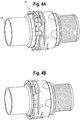
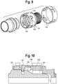
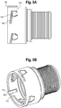
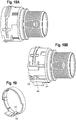
- FIGS. 7-10 An embodiment of the quick connector with positive locking indication 120 is illustrated in FIGS. 7-10 .
- the housing 122 includes one or more inwardly oriented flexible catch elements 124 that cooperate with the circumferential groove 62 in the male adapter 24.
- the housing 122 includes a ring groove 126 internally to accommodate a seal such as a V-ring or O-ring seal (not shown) and the connector 120 includes a sealing ring 128.
- An outer twist ring 144 is positioned on the housing 122 overlying the catch elements 124.
- the twist ring 144 includes one or more windows 146, each configured to cooperate with one of the catch elements 124. In an unlocked state, the windows 146 overlie a catch element 124.
- An outwardly projecting slide wall 148 is positioned over the outwardly projecting wall 140 that defines the aligning channel 138. The slide wall 148 is wider than the aligning channel wall 140 to permit the twist ring 144 to move (to be rotated) so that the windows 146 overlie the catch elements 124 and block the catch elements 124 to prevent the elements 124 from flexing outwardly.
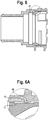
- the twist ring 144 is rotated to the unlocked state, in which the windows 146 overlie the catch elements 124.
- the male adapter 24 is aligned with the housing 122 so that the aligning channels 138 and adapter projections 66 are aligned with one another.
- the sloped collar 61 engages the catch elements 124 and the catch elements 124 ride up along the collar 61.
- the catch elements 124 will engage or seat in the adapter groove 62.
- the twist ring 144 can be rotated so that the solid wall portion of the ring 144 overlies the catch elements 124 and prevents the catch elements 124 from flexing outward and disengaging from the adapter groove 62.
- the ring 144 can include a series of tongues 150 that extend inwardly of the ring 144, adjacent to the windows 146. The tongues 150 traverse through and along the circumferential channel 134 along the end of and adjacent the catch elements 124. This provides a guide along which the ring 144 is captured, but can rotate, back and forth, to expose and cover the windows 146, while ensuring that the ring 144 remains on the housing 122.
- the connector 120 provides positive indication that the male adapter 24 is fully engaged with and seated in the housing 122 when the ring 146 is rotated to the locked position. If the adapter 24 is not fully seated in the housing 122, the ring 144 cannot rotate as the catch elements 124 will extend above the housing surface 132 and into the ring windows 146.
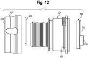
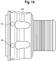
- the adapter 24 When the male adapter 24 is inserted into the housing 222, the adapter 24 contacts the tab 234 and the sliding ring 228 which urges the sliding ring 228 into the housing 222, which moves the sliding ring 228 out of interference with the clip legs 246.
- the twist ring 232 can then be rotated which in turn moves the clip legs 246 out of the pockets 244 and compresses the legs 246 which lock into the male adapter groove 62.
- the markers 242 on the twist ring 232 and housing body 224 can be positioned so that the markers 242 align when the twist ring 232 is in the locked state.
- the quick connector 220 thus provides positive visual indication of the state of the connector 220 by visually inspecting alignment of the markers 242 on the twist ring 232 and housing body 224. If the alignment markers 242 are raised on or recessed in the twist ring 232 and housing body 224, tactile indication can also be provided.
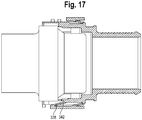
- the sliding indicator ring 326 includes a pair of circumferentially opposing inwardly oriented flexible tabs 332 that engage a channel 334 in the housing body 324.
- the tabs 332 engage the channel 334 as the sliding indicator ring 326 slides between a first or forward position ( FIG. 16 ) in which the ring 326 indicates that the male adapter 24 is not fully engaged with the housing 322 and a second rearward position ( FIG. 17 ) in which the ring 326 indicates that the male adapter 24 is fully engaged with the housing 322.
- the tabs 332 are biased outwardly to maintain positive engagement with the housing 322 and are prevented from passing beyond the fully engaged position by stop walls 336 in the channel 334.
- the sliding indicator ring 326 includes an additional tab, a release tab 338, that is forward of the pair of tabs 332.
- the release tab 338 moves within a release tab channel 340 that is formed in one of the first tab channels 334 and is further open to one of the longitudinal aligning channels 330 in the housing body 324.
- the release tab 338 locks and releases the sliding indicator ring 326 to prevent or allow movement of the ring 326 between the forward and rearward positions.
- the release 338 tab is biased outwardly and engages a stop wall 342 in the release tab channel 340 to prevent movement of the sliding indicator ring 326 (see FIG. 16 ).
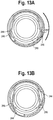
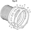
- the female housing 422 includes a body 424 having a plurality of circumferentially extending windows 426, an indicator ring 428 , a sliding ring 430 and a spring clip 432.
- the indicator ring 428 can be formed, for example, having two colors, for example, a red portion and a black portion, each extending along a longitudinal portion of the indicator ring 428. The indicator ring 428 is engaged by the sliding ring 430 and is moved longitudinally through the housing body 424 by the sliding ring 430.
- the male adapter 24 in the unassembled state ( FIG. 23A ), the male adapter 24 is not yet fully engaged with the housing 422 and the sliding and indicator rings 430, 428, and a forward portion or color (for example, the black portion) of the indicator ring 428 visible in the windows 426.
- the sliding ring 430 urges the indicator ring 428 rearward so that the second portion or color (for example, the red portion) of the indicator ring 428 is visible in the windows 426.
- the indicator ring 428 is beyond the housing longitudinal openings 434 and the clip legs 436 have passed over the sloped collar 61 and locked into the groove 62 in the adapter 24 to secure the adapter 24 and housing 422 to one another.
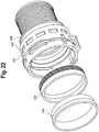
- FIGS. 26A and 26B Still another embodiment of the quick connector with positive lock indication 620, is shown in FIGS. 26A and 26B .
- the female housing 622 includes a series of pockets 636 and the sealing ring 626 includes a series of projections 658, similar to the prior embodiments.
- the ring 626 can include an aligning projection (not shown) that cooperates with the female housing aligning channel 664 to ensure that the ring 626 and female housing 622 are properly aligned.
- the other features, such as those to support and retain the spring clip 630 on the female housing 622 and between and when the ring 626 is properly seated in the female housing 622 are also present in this embodiment.
- an end 676 of the sealing ring 626 includes a series of helical or spiral formed legs 678 that define a circumferential radius about equal to the circumference of the sealing ring end 676. That is, the legs 678 are axially aligned with the sealing ring end 676.
- the legs 678 are formed so as to flex toward and away from the sealing ring end 676, and to bias the sealing ring 626 away from the female housing 622, to unseat the sealing ring 626 and as such, to unseat the sealing ring projections 658 from the female housing pockets 636.
- the legs 678 contact or cooperate with an abutment 668 in the housing 622. That is, the legs 678 compress against the abutment portion 688 as the sealing ring 626 properly seats in the housing 622.
- This arrangement provides, as in the prior embodiments, both visual and tactile indication of whether the sealing ring 626 is properly seated in the female housing 622 in that the projections 658 are seated in and flush with the pockets 636 when the sealing ring 626 is properly seated in the housing 622.
- the legs 678 can be formed through wall, that is formed from the entirety of the thickness of the wall at the sealing ring end 676, or it they can be formed from a portion of the wall, that is less than the entire thickness of the end 676 wall. When formed as a portion of the thickness of the end 676 wall, the legs 678, when flexed rearward, can seat in recesses 680 in the wall. Such a configuration facilitates protecting the legs 678. Moreover, in this configuration, the circumferential arrangement of the legs 678 is such that they do not occupy the area in which the sealing ring 626 acts to retain the seal 628 in place in the housing 622.
- the housing can be formed with slots or cut-outs 682 in the sidewall to accommodate the legs 678 and to prevent rotation of the sealing ring 626 relative to the housing 622.
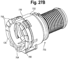
- a seal 728 is positioned in the female housing 722 and sits between an abutment 768 in the female housing 722 and the sealing ring 726 when the ring 726 is in place in the housing 722.
- an end 775 of the ring 726 includes a circumferential abutment portion 752.
- an intermediate portion 769 of the sealing ring 726 includes a partially open region 770 having a pair of linear or generally longitudinally extending flexible legs 772 that depend from an end 756 proximal the projections 758.
- the legs 772 are formed radially outwardly of the abutment portion 752.
- the legs 772 are configured to flex outwardly, circumferentially from each other and serve as a spring, as is detailed below.
- two pairs of legs 772 are formed, each on circumferentially opposing sides of the ring 726.
- the female housing 722 includes a receiving region 774 to receive the ring legs 772.
- the receiving region 774 includes a longitudinally extending wedge-shaped projection or wall 776 on an inner surface 778 thereof.
- the wedge wall 776 is configured to cooperate with the legs 772 to bias the sealing ring 726 outwardly, away from the housing 722 until it is full seated in the housing 722.
- the wedge wall 776 has a pair of mirror-image wedges 780 that cooperate with the pair of legs 772.
- the female housing 722 has receiving regions 774 formed on circumferentially opposing sides of the housing 722 to accommodate a sealing ring 726 configuration having a two pairs of legs 772.
- the sealing ring is translated between the seated and unseated positions by a component other than the seal, by an axial force applied to the sealing ring.
- the force is provided by a sealing ring having spiral or helical legs 678 that cooperate with the abutment wall 668 to unseat the sealing ring from the housing 622 and in the embodiment of FIGS. 27A , B , the force is provided by linear legs 772 that cooperate with the wedges 780.
- the bias function can be provided using other spring configurations.
- the under-surfaces of the projections 658, 758 that is those surfaces that form a juncture with the body of their respective rings, 626, 726, can be radiused or rounded to provide additional tactile indication of the alignment of the rings 626, 726 with their respective housings 622, 722.
- seal such as that shown in FIG. 3
- V-seal the seal
- other types and profiles of seals and cooperating ring grooves can be used and are within the scope and spirit of the present disclosure.
Landscapes
- Engineering & Computer Science (AREA)
- General Engineering & Computer Science (AREA)
- Mechanical Engineering (AREA)
- Quick-Acting Or Multi-Walled Pipe Joints (AREA)
Applications Claiming Priority (3)
| Application Number | Priority Date | Filing Date | Title |
|---|---|---|---|
| US201662428815P | 2016-12-01 | 2016-12-01 | |
| EP17817445.4A EP3548785B1 (de) | 2016-12-01 | 2017-11-22 | Schnellkupplung mit verriegelungsring |
| PCT/US2017/062985 WO2018102213A1 (en) | 2016-12-01 | 2017-11-22 | Quick connector with positive lock indication |
Related Parent Applications (2)
| Application Number | Title | Priority Date | Filing Date |
|---|---|---|---|
| EP17817445.4A Division EP3548785B1 (de) | 2016-12-01 | 2017-11-22 | Schnellkupplung mit verriegelungsring |
| EP17817445.4A Division-Into EP3548785B1 (de) | 2016-12-01 | 2017-11-22 | Schnellkupplung mit verriegelungsring |
Publications (2)
| Publication Number | Publication Date |
|---|---|
| EP3715691A2 true EP3715691A2 (de) | 2020-09-30 |
| EP3715691A3 EP3715691A3 (de) | 2020-10-28 |
Family
ID=60703071
Family Applications (2)
| Application Number | Title | Priority Date | Filing Date |
|---|---|---|---|
| EP17817445.4A Active EP3548785B1 (de) | 2016-12-01 | 2017-11-22 | Schnellkupplung mit verriegelungsring |
| EP20174975.1A Withdrawn EP3715691A3 (de) | 2016-12-01 | 2017-11-22 | Schnellkupplung mit positiver verriegelungsanzeige |
Family Applications Before (1)
| Application Number | Title | Priority Date | Filing Date |
|---|---|---|---|
| EP17817445.4A Active EP3548785B1 (de) | 2016-12-01 | 2017-11-22 | Schnellkupplung mit verriegelungsring |
Country Status (3)
| Country | Link |
|---|---|
| US (1) | US11480277B2 (de) |
| EP (2) | EP3548785B1 (de) |
| WO (1) | WO2018102213A1 (de) |
Families Citing this family (28)
| Publication number | Priority date | Publication date | Assignee | Title |
|---|---|---|---|---|
| DE102018219440A1 (de) | 2018-11-14 | 2020-05-14 | Fränkische Industrial Pipes GmbH & Co. KG | Verbindungseinheit |
| CN110043731B (zh) * | 2019-04-12 | 2020-11-10 | A.雷蒙德公司 | 快速连接器 |
| EP3736481B1 (de) | 2019-05-07 | 2022-01-19 | A. Raymond et Cie | Schnellverbinderanordnung mit verifizierungslasche |
| US11796099B2 (en) | 2019-08-22 | 2023-10-24 | Cooper-Standard Automotive Inc. | Connector having a pilot with an indicator |
| AT522804B1 (de) | 2019-09-03 | 2021-02-15 | Henn Gmbh & Co Kg | Steckverbinder zum Verbinden von Leitungen für flüssige oder gasförmige Medien |
| ES2823374B2 (es) * | 2019-11-05 | 2022-05-06 | Cikautxo S Coop | Conjunto conector con detección de ensamblaje y visualización de código simultáneo |
| DE102020108073A1 (de) * | 2020-03-24 | 2021-09-30 | Voss Automotive Gmbh | Steckverbinder mit Vormontagesicherung |
| EP3904747B1 (de) * | 2020-04-27 | 2024-02-14 | Illinois Tool Works Inc. | Buchse und verbinderanordnung |
| CN113639120B (zh) * | 2020-04-27 | 2025-12-02 | 伊利诺斯工具制品有限公司 | 母接头以及接头组件 |
| AT523066B1 (de) | 2020-05-27 | 2021-05-15 | Henn Gmbh & Co Kg | Steckverbinder zum Verbinden von Leitungen für flüssige oder gasförmige Medien |
| DE102020115021A1 (de) | 2020-06-05 | 2021-12-09 | Norma Germany Gmbh | Vorrichtung zum Verbinden zweier röhrenförmiger Objekte |
| US11698157B2 (en) | 2020-07-24 | 2023-07-11 | Cooper-Standard Automotive Inc. | Quick connector latch verification utilizing a scannable code |
| US11365840B2 (en) | 2020-11-20 | 2022-06-21 | A. Raymond Et Cie | Code verification sleeve for a quick connector |
| US11578828B2 (en) | 2020-12-03 | 2023-02-14 | Cooper-Standard Automotive, Inc. | Connector having a guided pilot |
| FR3126027B1 (fr) * | 2021-08-06 | 2023-08-11 | Parker Hannifin Emea Sarl | Dispositif de raccordement instantané |
| AT524862B1 (de) | 2021-11-09 | 2022-10-15 | Henn Gmbh & Co Kg | Steckverbinder zum Verbinden von Leitungen für flüssige oder gasförmige Medien |
| AT525044B1 (de) | 2022-01-11 | 2022-12-15 | Henn Gmbh & Co Kg | Steckerbaugruppe mit einem Steckverbinder und einem Gegensteckverbinder |
| WO2023133605A1 (de) | 2022-01-11 | 2023-07-20 | Henn Gmbh & Co Kg. | Steckerbaugruppe mit einem steckverbinder und einem gegensteckverbinder |
| AU2022202293B1 (en) * | 2022-04-06 | 2023-01-05 | Philmac Pty Ltd | A push-fit pipe fitting with a visual indicator |
| AT525974B1 (de) | 2022-09-27 | 2023-10-15 | Henn Gmbh & Co Kg | Steckverbinder zum Verbinden von Leitungen für flüssige oder gasförmige Medien, sowie ein Verfahren zum Herstellen einer Steckverbindung zwischen dem Steckverbinder und einem Gegensteckverbinder |
| US20240159340A1 (en) * | 2022-11-16 | 2024-05-16 | Cooper-Standard Automotive Inc | Connector with guiding components |
| DE202023100891U1 (de) * | 2023-02-24 | 2024-02-27 | Neoperl Gmbh | Befestigungsvorrichtung zur Befestigung von Schläuchen an einer Sanitärarmatur |
| AT526428B1 (de) | 2023-04-06 | 2024-03-15 | Henn Gmbh & Co Kg | Steckverbinder |
| EP4695544A1 (de) | 2023-04-14 | 2026-02-18 | Henn GmbH & Co KG. | Steckverbinder zur verbindung einer ersten fluidleitung mit einer zweiten fluidleitung |
| WO2024250048A1 (de) | 2023-06-05 | 2024-12-12 | Henn Gmbh & Co Kg. | Steckverbinder zur verbindung einer einsteckhülse mit einer fluidleitung |
| AT526786B1 (de) | 2023-08-11 | 2024-07-15 | Henn Gmbh & Co Kg | Steckverbinder zum Verbinden einer ersten Fluidleitung mit einer zweiten Fluidleitung |
| US12498066B1 (en) * | 2024-06-12 | 2025-12-16 | Ho Sing Enterprises Co., Ltd. | Quick connector structure of fluid shock absorber |
| US12553552B1 (en) * | 2024-08-14 | 2026-02-17 | Robert Sherwood | Conduit coupler |
Citations (2)
| Publication number | Priority date | Publication date | Assignee | Title |
|---|---|---|---|---|
| WO2013070865A2 (en) | 2011-11-10 | 2013-05-16 | Illinois Tool Works Inc. | Device for connecting two conduit sections |
| WO2016081590A1 (en) | 2014-11-20 | 2016-05-26 | Illinois Tool Works Inc. | Quick connector |
Family Cites Families (7)
| Publication number | Priority date | Publication date | Assignee | Title |
|---|---|---|---|---|
| US4948176A (en) * | 1987-09-14 | 1990-08-14 | Proprietary Technology, Inc. | Swivelable quick connector assembly |
| DE102004044917A1 (de) * | 2004-09-14 | 2006-03-16 | Fte Automotive Gmbh | Lösbare Steckverbindung für Rohrleitungen od. dgl. |
| US20060145475A1 (en) * | 2004-12-30 | 2006-07-06 | Itt Manufacturing Enterprises, Inc. | Fluid quick connector with wire retainer |
| US9283344B2 (en) * | 2012-01-03 | 2016-03-15 | Carefusion Corporation | Apparatus, system, and method of fluid delivery connection |
| US8851526B2 (en) * | 2012-01-11 | 2014-10-07 | GM Global Technology Operations LLC | Cap for a quick connect fitting assembly and method of assembly using same |
| PL3149381T3 (pl) | 2014-05-30 | 2019-04-30 | Oetiker Ny Inc | Złącze dla płynu z nasadką zabezpieczającą całkowite wstawienie z pomocniczymi zatrzaskami |
| JP6168559B2 (ja) * | 2014-08-07 | 2017-07-26 | 株式会社ニフコ | 管状体のロック機構 |
-
2017
- 2017-11-22 WO PCT/US2017/062985 patent/WO2018102213A1/en not_active Ceased
- 2017-11-22 US US16/465,338 patent/US11480277B2/en active Active
- 2017-11-22 EP EP17817445.4A patent/EP3548785B1/de active Active
- 2017-11-22 EP EP20174975.1A patent/EP3715691A3/de not_active Withdrawn
Patent Citations (2)
| Publication number | Priority date | Publication date | Assignee | Title |
|---|---|---|---|---|
| WO2013070865A2 (en) | 2011-11-10 | 2013-05-16 | Illinois Tool Works Inc. | Device for connecting two conduit sections |
| WO2016081590A1 (en) | 2014-11-20 | 2016-05-26 | Illinois Tool Works Inc. | Quick connector |
Also Published As
| Publication number | Publication date |
|---|---|
| EP3548785A1 (de) | 2019-10-09 |
| WO2018102213A1 (en) | 2018-06-07 |
| EP3715691A3 (de) | 2020-10-28 |
| US20190390808A1 (en) | 2019-12-26 |
| US11480277B2 (en) | 2022-10-25 |
| EP3548785B1 (de) | 2023-02-15 |
Similar Documents
| Publication | Publication Date | Title |
|---|---|---|
| US11480277B2 (en) | Quick connector with positive lock indication | |
| US6702254B2 (en) | Universal safety coupler | |
| CN111379915B (zh) | 快速连接器 | |
| US6520546B2 (en) | Quick connector release tool | |
| EP3054206B1 (de) | Leitungsanschluss mit einer ersten und zweiten verriegelung | |
| US7658420B2 (en) | Quick-connect fitting with unlocking ring | |
| US5934709A (en) | Fluid couplings | |
| CN109477604A (zh) | 连接器 | |
| US8201853B2 (en) | Clamping coupling element and a coupling including such an element | |
| US6757950B2 (en) | Rotatable quick connector stuffer pin | |
| US11796099B2 (en) | Connector having a pilot with an indicator | |
| US7762593B2 (en) | Ball coupler | |
| KR20190093112A (ko) | 듀얼-래치 퀵커넥터 | |
| JP2015055357A (ja) | ボタン解除に用いる一体ばねアームを含むラッチを有するクイックコネクト流体導管コネクタ | |
| WO2005116509A1 (ja) | クイックコネクタ | |
| US9175795B2 (en) | Coupling with locking bars | |
| CN109555925B (zh) | 断路器和包括这种断路器的用于加压流体的处理设备 | |
| EP3232108B1 (de) | Rohrverbindung | |
| CN111102411A (zh) | 快速连接器、滑动锁及套接部件 | |
| US6412826B1 (en) | High pressure quick connector | |
| EP0824646A1 (de) | Schnellkupplung mit ring zur sicherung der korrekten verbindung | |
| AU2025200945A1 (en) | Pneumatic coupling | |
| AU681268B2 (en) | Fluid couplings | |
| EP1724511A2 (de) | Schnellverbinder mit Halteelement | |
| WO2023013688A1 (ja) | コネクタ及びソケット |
Legal Events
| Date | Code | Title | Description |
|---|---|---|---|
| PUAI | Public reference made under article 153(3) epc to a published international application that has entered the european phase |
Free format text: ORIGINAL CODE: 0009012 |
|
| STAA | Information on the status of an ep patent application or granted ep patent |
Free format text: STATUS: THE APPLICATION HAS BEEN PUBLISHED |
|
| PUAL | Search report despatched |
Free format text: ORIGINAL CODE: 0009013 |
|
| AC | Divisional application: reference to earlier application |
Ref document number: 3548785 Country of ref document: EP Kind code of ref document: P |
|
| AK | Designated contracting states |
Kind code of ref document: A2 Designated state(s): AL AT BE BG CH CY CZ DE DK EE ES FI FR GB GR HR HU IE IS IT LI LT LU LV MC MK MT NL NO PL PT RO RS SE SI SK SM TR |
|
| AK | Designated contracting states |
Kind code of ref document: A3 Designated state(s): AL AT BE BG CH CY CZ DE DK EE ES FI FR GB GR HR HU IE IS IT LI LT LU LV MC MK MT NL NO PL PT RO RS SE SI SK SM TR |
|
| RIC1 | Information provided on ipc code assigned before grant |
Ipc: F16L 37/088 20060101AFI20200921BHEP |
|
| STAA | Information on the status of an ep patent application or granted ep patent |
Free format text: STATUS: REQUEST FOR EXAMINATION WAS MADE |
|
| 17P | Request for examination filed |
Effective date: 20210329 |
|
| RBV | Designated contracting states (corrected) |
Designated state(s): AL AT BE BG CH CY CZ DE DK EE ES FI FR GB GR HR HU IE IS IT LI LT LU LV MC MK MT NL NO PL PT RO RS SE SI SK SM TR |
|
| STAA | Information on the status of an ep patent application or granted ep patent |
Free format text: STATUS: EXAMINATION IS IN PROGRESS |
|
| 17Q | First examination report despatched |
Effective date: 20220720 |
|
| STAA | Information on the status of an ep patent application or granted ep patent |
Free format text: STATUS: THE APPLICATION IS DEEMED TO BE WITHDRAWN |
|
| 18D | Application deemed to be withdrawn |
Effective date: 20221201 |