EP3715694A2 - Dispositif de raccordement et de réparation des sections de tuyau d'un tuyau, en particulier d'un tuyau pehd - Google Patents
Dispositif de raccordement et de réparation des sections de tuyau d'un tuyau, en particulier d'un tuyau pehd Download PDFInfo
- Publication number
- EP3715694A2 EP3715694A2 EP20164776.5A EP20164776A EP3715694A2 EP 3715694 A2 EP3715694 A2 EP 3715694A2 EP 20164776 A EP20164776 A EP 20164776A EP 3715694 A2 EP3715694 A2 EP 3715694A2
- Authority
- EP
- European Patent Office
- Prior art keywords
- pipe
- clamping sleeve
- coupling
- gripping teeth
- coupling rings
- Prior art date
- Legal status (The legal status is an assumption and is not a legal conclusion. Google has not performed a legal analysis and makes no representation as to the accuracy of the status listed.)
- Granted
Links
Images

Classifications
-
- F—MECHANICAL ENGINEERING; LIGHTING; HEATING; WEAPONS; BLASTING
- F16—ENGINEERING ELEMENTS AND UNITS; GENERAL MEASURES FOR PRODUCING AND MAINTAINING EFFECTIVE FUNCTIONING OF MACHINES OR INSTALLATIONS; THERMAL INSULATION IN GENERAL
- F16L—PIPES; JOINTS OR FITTINGS FOR PIPES; SUPPORTS FOR PIPES, CABLES OR PROTECTIVE TUBING; MEANS FOR THERMAL INSULATION IN GENERAL
- F16L55/00—Devices or appurtenances for use in, or in connection with, pipes or pipe systems
- F16L55/16—Devices for covering leaks in pipes or hoses, e.g. hose-menders
- F16L55/168—Devices for covering leaks in pipes or hoses, e.g. hose-menders from outside the pipe
- F16L55/17—Devices for covering leaks in pipes or hoses, e.g. hose-menders from outside the pipe by means of rings, bands or sleeves pressed against the outside surface of the pipe or hose
- F16L55/172—Devices for covering leaks in pipes or hoses, e.g. hose-menders from outside the pipe by means of rings, bands or sleeves pressed against the outside surface of the pipe or hose the ring, band or sleeve being tightened by a tangentially arranged threaded pin and a nut
-
- F—MECHANICAL ENGINEERING; LIGHTING; HEATING; WEAPONS; BLASTING
- F16—ENGINEERING ELEMENTS AND UNITS; GENERAL MEASURES FOR PRODUCING AND MAINTAINING EFFECTIVE FUNCTIONING OF MACHINES OR INSTALLATIONS; THERMAL INSULATION IN GENERAL
- F16L—PIPES; JOINTS OR FITTINGS FOR PIPES; SUPPORTS FOR PIPES, CABLES OR PROTECTIVE TUBING; MEANS FOR THERMAL INSULATION IN GENERAL
- F16L21/00—Joints with sleeve or socket
- F16L21/06—Joints with sleeve or socket with a divided sleeve or ring clamping around the pipe ends
-
- F—MECHANICAL ENGINEERING; LIGHTING; HEATING; WEAPONS; BLASTING
- F16—ENGINEERING ELEMENTS AND UNITS; GENERAL MEASURES FOR PRODUCING AND MAINTAINING EFFECTIVE FUNCTIONING OF MACHINES OR INSTALLATIONS; THERMAL INSULATION IN GENERAL
- F16L—PIPES; JOINTS OR FITTINGS FOR PIPES; SUPPORTS FOR PIPES, CABLES OR PROTECTIVE TUBING; MEANS FOR THERMAL INSULATION IN GENERAL
- F16L21/00—Joints with sleeve or socket
- F16L21/002—Sleeves or nipples for pipes of the same diameter; Reduction pieces
- F16L21/005—Sleeves or nipples for pipes of the same diameter; Reduction pieces made of elastic material, e.g. partly or completely surrounded by clamping devices
-
- F—MECHANICAL ENGINEERING; LIGHTING; HEATING; WEAPONS; BLASTING
- F16—ENGINEERING ELEMENTS AND UNITS; GENERAL MEASURES FOR PRODUCING AND MAINTAINING EFFECTIVE FUNCTIONING OF MACHINES OR INSTALLATIONS; THERMAL INSULATION IN GENERAL
- F16L—PIPES; JOINTS OR FITTINGS FOR PIPES; SUPPORTS FOR PIPES, CABLES OR PROTECTIVE TUBING; MEANS FOR THERMAL INSULATION IN GENERAL
- F16L21/00—Joints with sleeve or socket
- F16L21/06—Joints with sleeve or socket with a divided sleeve or ring clamping around the pipe ends
- F16L21/065—Joints with sleeve or socket with a divided sleeve or ring clamping around the pipe ends tightened by tangentially-arranged threaded pins
-
- F—MECHANICAL ENGINEERING; LIGHTING; HEATING; WEAPONS; BLASTING
- F16—ENGINEERING ELEMENTS AND UNITS; GENERAL MEASURES FOR PRODUCING AND MAINTAINING EFFECTIVE FUNCTIONING OF MACHINES OR INSTALLATIONS; THERMAL INSULATION IN GENERAL
- F16L—PIPES; JOINTS OR FITTINGS FOR PIPES; SUPPORTS FOR PIPES, CABLES OR PROTECTIVE TUBING; MEANS FOR THERMAL INSULATION IN GENERAL
- F16L21/00—Joints with sleeve or socket
- F16L21/08—Joints with sleeve or socket with additional locking means
Definitions
- the present invention describes a device for connecting and / or repairing pipe sections of a pipe, in particular an HDPE pipe, according to the preamble of the first claim.
- the device according to the invention relates in particular to a device which on the one hand connects two pipe sections of a pipe or on the other hand repairs a damaged section of a pipe in order to obtain a functional pipe suitable for conveying a liquid.
- Coupling devices in the form of a clamping sleeve for example in the document, are known US 2012/0242083 A1 shown.
- the ones from the US 2012/0242083 A1 known coupling device can be placed around an existing pipeline.
- This known coupling device “Arpol MultiFix” also has several limiting rods that can be connected to the clamping sleeve to achieve axial tensile strength.
- the «Arpol MultiFix» coupling device has the disadvantage, however, that the construction is complicated and handling is difficult.
- the present invention has set itself the task of providing a coupling device for connecting and repairing pipe sections of a pipe, in particular HDPE pipe, which overcomes the disadvantages of the known prior art and in particular has a simplified and compact design.
- a third axial extension of a coupling ring is in a ratio of preferably 1 to 5 to 10, more preferably 2 to 4 to 10, most preferably about 3 to 10, compared to a second axial extension of the clamping sleeve.
- the coupling device according to the invention achieved here has the advantage of a compact and easily manageable construction due to the two relatively small coupling rings, the coupling device according to the invention being easily portable even with larger dimensions.
- the at least two coupling rings arranged on both sides of the clamping sleeve can each be accommodated in a flange bearing with a U-shaped cross-section, so that tensile forces acting on the pipe sections in the installed state are compensated for the formation of an axially tensile repair coupling and so that the tension achieved by the clamping sleeve Sealing area and the axial tensile strength achieved by the coupling rings is spatially separated.
- the coupling device according to the invention advantageously allows a connection of two pipe sections of a pipe that is independent of the weather and can even be carried out under water.
- the coupling device according to the invention is suitable as a tensile, open repair coupling.
- HDPE high density polyethylene
- repairing a pipe can be understood to mean the elimination of defects such as pipe cracks, breaks, punctures and the like.
- connecting pipe sections of a pipe can be understood, among other things, to mean that pipe sections can be laid quickly without welding.
- the coupling device according to the invention advantageously allows the sealing area achieved by the clamping sleeve and the through the coupling rings achieved, axial tensile strength is spatially separated. This results in the further advantage that the gripping teeth are freely movable and have no negative influence on the sealing by the sealing element or sealing sleeve of the clamping sleeve.
- the coupling rings that can be attached on both sides can also be understood as anchor rings.
- an axial tensile strength is understood to mean that the axial mobility of the connected pipe sections is prevented or reduced as far as possible.
- the coupling device according to the invention ensures such an axial tensile strength at a fluid pressure in the pipe of up to 16 bar.
- the coupling device according to the invention already ensures the necessary tightness without attaching additional support rings. Nevertheless, it is optionally conceivable that the coupling device according to the invention has support rings.
- a first axial extension of each flange bearing is preferably in a ratio of preferably 1 to 4 to 10, more preferably 1 to 3 to 10, most preferably about 2 to 10, compared to a second axial extension of the clamping sleeve.
- a flange bearing is understood to mean a bearing element which is designed to receive or support a coupling ring.
- the gripping teeth of the at least two coupling rings are preferably aligned with the clamping sleeve in order to increase the axial tensile strength.
- the gripping teeth are preferably made of aluminum and / or stainless steel and / or a plastic suitable for injection molding and continuous casting.
- the gripping teeth of the at least two coupling rings are preferably interchangeable or, if they are worn, they can be replaced by the gripping teeth having a bore with an internal thread and each being fastened to a coupling ring using a corresponding screw element or riveting.
- an angular distance ⁇ between two adjacent gripping teeth of a coupling ring is preferably between 10 ° to 30 °, more preferably between 15 ° to 25 °, most preferably about 20 ° to 25 ° °.
- the gripping teeth are preferably arranged and designed in such a way that the gripping teeth can engage the pipe up to a maximum of 10%.
- the gripping teeth are arranged in several rows and in particular offset at an angle in the at least two coupling rings, so that a particularly high axial tensile strength is achieved, in particular for high nominal pressures and / or large pipe diameters.
- the sealing element of the coupling device according to the invention is preferably made of ethylene propylene diene rubber (EPDM) and / or nitrile butadiene rubber (NBR).
- EPDM ethylene propylene diene rubber
- NBR nitrile butadiene rubber
- the device is preferably designed in such a way that the closing area of the coupling rings can be offset with respect to the closing area of the clamping sleeve, preferably by 45 ° to 90 °, more preferably by 60 ° to 90 °, very particularly preferably by 90 °, so that greater strength is achieved becomes.
- This displaceability or rotatability has the advantage that, in the event of a torsion of the pipe or the pipeline, the closing areas can also rotate.
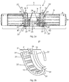
- Fig.1a shows a perspective view of a preferred embodiment of the coupling device 1 according to the invention in the assembled or installed state, which provides a connection between the pipe sections R1; R2 of a pipe R, in particular an HDPE pipe, produces.
- the coupling device 1 here comprises a clamping sleeve 5 with an attachable or attached sealing element facing the pipe, which cannot be seen here (see FIG Fig.1b respectively Fig.2a ) as well as with a pipe clamp 9 surrounding the sealing element 10 for producing a sealing connection between the pipe sections R1; R2 of a pipe R.
- Fig.1a here two coupling rings 2 '; 2 "in mechanical operative connection with the clamping sleeve 5 for fastening the coupling device 1 to the pipe R.
- the two coupling rings 2';2" arranged here on both sides of the clamping sleeve 5 are each in one, with one, in particular U-shaped, cross-sectional flange bearings 3 '; 3 "can be received, so that in the installed state, tensile forces acting on the pipe sections R1; R2 are compensated for the formation of an axially tensile repair coupling, and so that the sealing area achieved by the clamping sleeve 5 and that by the Coupling rings 2 '; 2 "achieved, axial tensile strength is spatially separated to prevent a negative influence on the tightness of the sealing element, not shown here.
- the clamping sleeve 5 has two clamping sleeve elements 27 here.
- the coupling device 1 is designed in such a way that the closing area S1 of the two coupling rings 2 '; 2 "can be offset from the closing area S2 of the clamping sleeve 6, preferably by 45 ° to 90 °, more preferably by 60 ° up to 90 °, very particularly preferably 90 °, so that a higher strength is achieved.
- the closing area S1 is formed here by two second fastening bolts 21 which are operatively connected to each other with a second receiving tab 23 '; 23 "and a second bolt element 24';24” which can be received in the second receiving tab 23 '; 23 "(see FIG Fig.2b ).
- the second fastening bolts 21 can have an external thread and the second bolt elements 24 '; 24 "have a bore with a corresponding internal thread, so that a closing movement of a coupling ring 2';2" can be achieved by actuating or rotating the second fastening bolt 21.
- the closing area S2 of the clamping sleeve 6 is formed here by a first first fastening bolt 20 that is operatively connected to a first receiving tab 25 and a first bolt element 26 that can be received in the first receiving tab 25.
- a first bolt element 26 can be received in a first receiving tab 25 and the first bolt elements 26 are provided with two bores with an internal thread, an external thread of the first fastening bolt 20 being designed to correspond to the internal thread of the first bolt elements 26 and by actuation or by rotating the first fastening bolt 20, a closing movement of the clamping sleeve 6 can be achieved.
- a hinge (not shown here) can be provided for the rotatable connection of the clamping sleeve elements 27 of the clamping sleeve 6.
- the coupling device 1 Due to the design of the coupling device 1 with a locking area S1 or S2 provided clamping sleeve 6 or respectively Coupling rings 2 '; 2 ", the coupling device can be placed around an existing pipe for repair purposes.
- Fig.1b shows a perspective view of the coupling device 1 according to the invention in the assembled state without a pipe.
- the flange bearing 3 ′ can be seen to comprise two separate flange bearing elements 30 ′ formed on the pipe clip 9 of the clamping sleeve 5.
- the molded flange bearing elements 30 ' extend at least in sections over the circumference of the clamping sleeve 5.
- Fig.2a shows an in Fig.1a shown cross-section AA through the inventive coupling device 1 in the assembled state, which connects the pipe sections R1; R2 of a pipe R produces.
- clamping sleeve 5 is provided with double sealing lips 11 ′; 11 ′′ arranged at the ends on the sealing element 10 for sealing between the pipe R and the clamping sleeve 5.
- the two coupling rings 2 '; 2 here have a U-shaped cross-section.
- a receiving area A is formed in the U-shaped cross-section of the two coupling rings 2';2", with the at least two coupling rings 2 '; 2 "a plurality of gripping teeth 15 ';15" arranged here in a row are arranged.
- Fig.2a It can be seen that the gripping teeth 15 '; 15 "in the receiving area A of the two coupling rings 2';2” can be received or exchanged in that the gripping teeth 15 '; 15 “comprise a bore B with an internal thread and are here based on a corresponding screw element 16 a coupling ring 2 '; 2 "can be attached.
- Fig.2a also shows that the gripping teeth 15 '; 15 "of the at least two coupling rings 2';2" are oriented towards the clamping sleeve 5 in the installed state of the device 1 to increase the axial tensile strength, with one tooth element Z of the gripping teeth being particularly preferred over one Vertical has an orientation angle ⁇ of preferably 50 ° to 70 °, very particularly preferably about 60 °.
- the gripping teeth 15 '; 15 are arranged in several rows and in particular offset at an angle in the at least two coupling rings 2'; 2" so that a particularly high axial tensile strength is achieved, especially for high nominal pressures and / or large pipe diameters.
- the preferred embodiment of the coupling device 1 according to the invention shown has a third axial extension z of each coupling ring 2 '; 2 "compared to a second axial extension y of the clamping sleeve 5, the third axial extension z of a coupling ring 2';2" being compared to the second axial extension Extension y of the clamping sleeve 5 is in a ratio of preferably 1 to 5 to 10, more preferably 2 to 4 to 10, most preferably about 3 to 10.
- preferred Embodiment of the inventive coupling device 1 has a second axial extension y of each flange bearing 3 '; 3 "of the clamping sleeve 5, the first axial extension x of each flange bearing 3';3" being preferred over a second axial extension y of the clamping sleeve 5 in a ratio of 1 to 4 to 10, more preferably 1 to 3 to 10, most preferably about 2 to 10.
- Fig.2b shows an in Fig.1a shown cross section BB through a coupling ring 2 'of the coupling device 1 according to the invention in the assembled state without a pipe.
- a coupling ring 2 ' can be seen to be formed by two opposing coupling ring sections 22'.
- two opposing closing areas S1 between the two coupling ring sections 22 ' are two opposing closing areas S1 between the two coupling ring sections 22 '.
- the coupling device 1 preferably has an angular distance ⁇ between two adjacent gripping teeth 15 '; 15 "of a coupling ring 2'; 2", preferably between 10 ° to 30 °, more preferably between 15 ° to 25 °, am most preferably about 20 ° to 25 °.
- Fig.2c shows a cross-section through a gripping tooth 15 'of the preferred embodiment of the coupling device according to the invention, the respective tooth elements Z of the gripping teeth 15' having an orientation angle ⁇ of preferably 50 ° to 70 °, very particularly preferably about 60 °, with respect to a vertical.
Landscapes
- Engineering & Computer Science (AREA)
- General Engineering & Computer Science (AREA)
- Mechanical Engineering (AREA)
- Mutual Connection Of Rods And Tubes (AREA)
- Joints With Pressure Members (AREA)
- Pipe Accessories (AREA)
- Electric Cable Installation (AREA)
Applications Claiming Priority (1)
| Application Number | Priority Date | Filing Date | Title |
|---|---|---|---|
| CH00392/19A CH716001A2 (de) | 2019-03-26 | 2019-03-26 | Vorrichtung zum Verbinden und Reparieren von Rohrabschnitten eines Rohrs, insbesondere eines HDPE Rohrs. |
Publications (3)
| Publication Number | Publication Date |
|---|---|
| EP3715694A2 true EP3715694A2 (fr) | 2020-09-30 |
| EP3715694A3 EP3715694A3 (fr) | 2020-11-11 |
| EP3715694B1 EP3715694B1 (fr) | 2022-05-04 |
Family
ID=69953815
Family Applications (1)
| Application Number | Title | Priority Date | Filing Date |
|---|---|---|---|
| EP20164776.5A Active EP3715694B1 (fr) | 2019-03-26 | 2020-03-23 | Dispositif de raccordement et de réparation des sections de tuyau d'un tuyau, en particulier d'un tuyau pehd |
Country Status (4)
| Country | Link |
|---|---|
| EP (1) | EP3715694B1 (fr) |
| CH (1) | CH716001A2 (fr) |
| ES (1) | ES2924385T3 (fr) |
| MA (1) | MA53296A (fr) |
Cited By (1)
| Publication number | Priority date | Publication date | Assignee | Title |
|---|---|---|---|---|
| CN115898320A (zh) * | 2021-08-12 | 2023-04-04 | 中国石油天然气股份有限公司 | 注水泥封隔器 |
Citations (1)
| Publication number | Priority date | Publication date | Assignee | Title |
|---|---|---|---|---|
| US20120242083A1 (en) | 2011-03-22 | 2012-09-27 | Airvac Inc | Pipe coupling |
Family Cites Families (1)
| Publication number | Priority date | Publication date | Assignee | Title |
|---|---|---|---|---|
| US7665773B2 (en) * | 2006-06-21 | 2010-02-23 | Conocophillips Company | Self-tightening clamp assemblies for protection against full pipe separation |
-
2019
- 2019-03-26 CH CH00392/19A patent/CH716001A2/de unknown
-
2020
- 2020-03-23 EP EP20164776.5A patent/EP3715694B1/fr active Active
- 2020-03-23 ES ES20164776T patent/ES2924385T3/es active Active
- 2020-03-23 MA MA053296A patent/MA53296A/fr unknown
Patent Citations (1)
| Publication number | Priority date | Publication date | Assignee | Title |
|---|---|---|---|---|
| US20120242083A1 (en) | 2011-03-22 | 2012-09-27 | Airvac Inc | Pipe coupling |
Cited By (1)
| Publication number | Priority date | Publication date | Assignee | Title |
|---|---|---|---|---|
| CN115898320A (zh) * | 2021-08-12 | 2023-04-04 | 中国石油天然气股份有限公司 | 注水泥封隔器 |
Also Published As
| Publication number | Publication date |
|---|---|
| EP3715694A3 (fr) | 2020-11-11 |
| CH716001A2 (de) | 2020-09-30 |
| ES2924385T3 (es) | 2022-10-06 |
| MA53296A (fr) | 2022-02-16 |
| EP3715694B1 (fr) | 2022-05-04 |
Similar Documents
| Publication | Publication Date | Title |
|---|---|---|
| EP2035736B1 (fr) | Raccord par manchon | |
| DE602005002368T2 (de) | Anordnung zur Verbindung eines Kraftstoffspeichers für Kraftstoff unter Druck und mindestens einem Injektor, für eine Brennkraftmaschine | |
| DE69901568T2 (de) | Vorrichtung zur abdichtung eine leckage in einer rohrleitung | |
| DE2025416A1 (de) | Rohrkupplung | |
| DE3838935A1 (de) | Kupplungsstueck | |
| DE102014205626A1 (de) | Dichtungsvorrichtung | |
| EP2904301B1 (fr) | Verrou de maintien pour un raccord de tuyauterie avec manchon | |
| EP1798459A1 (fr) | Dispositif de raccord de tuyaux en deux demi-colliers de retenue | |
| EP3715694B1 (fr) | Dispositif de raccordement et de réparation des sections de tuyau d'un tuyau, en particulier d'un tuyau pehd | |
| DE102008004152A1 (de) | Rohrleitung mit einem Anschlussstück | |
| EP2607786B1 (fr) | Agencement avec un coude de tube pour transport de gaz d'échappement dans des installations de chauffage | |
| DE202023102110U1 (de) | Frostsichere Auslaufarmatur und Auslaufgehäuse einer Armatur | |
| DE202016106901U1 (de) | Rohrverbinder | |
| DE102015226536A1 (de) | Kabelverschraubung | |
| DE2911448A1 (de) | Rohrverbindung | |
| DE202020106261U1 (de) | Anschlussstutzen für Wellrohre | |
| DE102004018229B3 (de) | Fluidverteilvorrichtung | |
| DE202011102671U1 (de) | Vorrichtung zum Abdichten von Ringräumen | |
| EP3584487A1 (fr) | Bride tubulaire pour tuyaux d'air de combustion ainsi que système de gaz d'échappement | |
| DE202012003173U1 (de) | Formteil mit mindestens einer Steckmuffe aus Kunststoff sowie mit einer ringförmigen Lippendichtung und Rohrverbindungsanordnung mit einem solchen Formteil | |
| DE60216093T2 (de) | Rohrverbindung | |
| DE102024124747A1 (de) | Adapter zur Befestigung eines Belüfters an einem Verteilerrohr | |
| DE2937193A1 (de) | Rohrverbindungsvorrichtung | |
| DE2508424A1 (de) | Loesbare stossverbindung fuer brunnenrohre | |
| DE2324910A1 (de) | Loesbare anschlussverbindung fuer eine z. b. aus metall bestehende starre leitung |
Legal Events
| Date | Code | Title | Description |
|---|---|---|---|
| PUAI | Public reference made under article 153(3) epc to a published international application that has entered the european phase |
Free format text: ORIGINAL CODE: 0009012 |
|
| STAA | Information on the status of an ep patent application or granted ep patent |
Free format text: STATUS: THE APPLICATION HAS BEEN PUBLISHED |
|
| AK | Designated contracting states |
Kind code of ref document: A2 Designated state(s): AL AT BE BG CH CY CZ DE DK EE ES FI FR GB GR HR HU IE IS IT LI LT LU LV MC MK MT NL NO PL PT RO RS SE SI SK SM TR |
|
| AX | Request for extension of the european patent |
Extension state: BA ME |
|
| PUAL | Search report despatched |
Free format text: ORIGINAL CODE: 0009013 |
|
| AK | Designated contracting states |
Kind code of ref document: A3 Designated state(s): AL AT BE BG CH CY CZ DE DK EE ES FI FR GB GR HR HU IE IS IT LI LT LU LV MC MK MT NL NO PL PT RO RS SE SI SK SM TR |
|
| AX | Request for extension of the european patent |
Extension state: BA ME |
|
| RIC1 | Information provided on ipc code assigned before grant |
Ipc: F16L 21/06 20060101ALI20201008BHEP Ipc: F16L 21/08 20060101ALI20201008BHEP Ipc: F16L 55/172 20060101AFI20201008BHEP |
|
| STAA | Information on the status of an ep patent application or granted ep patent |
Free format text: STATUS: REQUEST FOR EXAMINATION WAS MADE |
|
| 17P | Request for examination filed |
Effective date: 20210507 |
|
| RAV | Requested validation state of the european patent: fee paid |
Extension state: MA Effective date: 20210507 Extension state: TN Effective date: 20210507 |
|
| RBV | Designated contracting states (corrected) |
Designated state(s): AL AT BE BG CH CY CZ DE DK EE ES FI FR GB GR HR HU IE IS IT LI LT LU LV MC MK MT NL NO PL PT RO RS SE SI SK SM TR |
|
| RIC1 | Information provided on ipc code assigned before grant |
Ipc: F16L 21/08 20060101ALI20210826BHEP Ipc: F16L 21/06 20060101ALI20210826BHEP Ipc: F16L 55/172 20060101AFI20210826BHEP |
|
| GRAP | Despatch of communication of intention to grant a patent |
Free format text: ORIGINAL CODE: EPIDOSNIGR1 |
|
| STAA | Information on the status of an ep patent application or granted ep patent |
Free format text: STATUS: GRANT OF PATENT IS INTENDED |
|
| GRAJ | Information related to disapproval of communication of intention to grant by the applicant or resumption of examination proceedings by the epo deleted |
Free format text: ORIGINAL CODE: EPIDOSDIGR1 |
|
| GRAP | Despatch of communication of intention to grant a patent |
Free format text: ORIGINAL CODE: EPIDOSNIGR1 |
|
| INTG | Intention to grant announced |
Effective date: 20211012 |
|
| INTG | Intention to grant announced |
Effective date: 20211104 |
|
| GRAS | Grant fee paid |
Free format text: ORIGINAL CODE: EPIDOSNIGR3 |
|
| GRAA | (expected) grant |
Free format text: ORIGINAL CODE: 0009210 |
|
| STAA | Information on the status of an ep patent application or granted ep patent |
Free format text: STATUS: THE PATENT HAS BEEN GRANTED |
|
| AK | Designated contracting states |
Kind code of ref document: B1 Designated state(s): AL AT BE BG CH CY CZ DE DK EE ES FI FR GB GR HR HU IE IS IT LI LT LU LV MC MK MT NL NO PL PT RO RS SE SI SK SM TR |
|
| REG | Reference to a national code |
Ref country code: GB Ref legal event code: FG4D Free format text: NOT ENGLISH |
|
| REG | Reference to a national code |
Ref country code: CH Ref legal event code: EP |
|
| REG | Reference to a national code |
Ref country code: AT Ref legal event code: REF Ref document number: 1489389 Country of ref document: AT Kind code of ref document: T Effective date: 20220515 |
|
| REG | Reference to a national code |
Ref country code: DE Ref legal event code: R096 Ref document number: 502020001036 Country of ref document: DE |
|
| REG | Reference to a national code |
Ref country code: IE Ref legal event code: FG4D Free format text: LANGUAGE OF EP DOCUMENT: GERMAN |
|
| REG | Reference to a national code |
Ref country code: SE Ref legal event code: TRGR |
|
| REG | Reference to a national code |
Ref country code: LT Ref legal event code: MG9D |
|
| RAP4 | Party data changed (patent owner data changed or rights of a patent transferred) |
Owner name: ABORRA AG |
|
| REG | Reference to a national code |
Ref country code: NL Ref legal event code: MP Effective date: 20220504 |
|
| REG | Reference to a national code |
Ref country code: ES Ref legal event code: FG2A Ref document number: 2924385 Country of ref document: ES Kind code of ref document: T3 Effective date: 20221006 |
|
| PG25 | Lapsed in a contracting state [announced via postgrant information from national office to epo] |
Ref country code: PT Free format text: LAPSE BECAUSE OF FAILURE TO SUBMIT A TRANSLATION OF THE DESCRIPTION OR TO PAY THE FEE WITHIN THE PRESCRIBED TIME-LIMIT Effective date: 20220905 Ref country code: NO Free format text: LAPSE BECAUSE OF FAILURE TO SUBMIT A TRANSLATION OF THE DESCRIPTION OR TO PAY THE FEE WITHIN THE PRESCRIBED TIME-LIMIT Effective date: 20220804 Ref country code: NL Free format text: LAPSE BECAUSE OF FAILURE TO SUBMIT A TRANSLATION OF THE DESCRIPTION OR TO PAY THE FEE WITHIN THE PRESCRIBED TIME-LIMIT Effective date: 20220504 Ref country code: LT Free format text: LAPSE BECAUSE OF FAILURE TO SUBMIT A TRANSLATION OF THE DESCRIPTION OR TO PAY THE FEE WITHIN THE PRESCRIBED TIME-LIMIT Effective date: 20220504 Ref country code: HR Free format text: LAPSE BECAUSE OF FAILURE TO SUBMIT A TRANSLATION OF THE DESCRIPTION OR TO PAY THE FEE WITHIN THE PRESCRIBED TIME-LIMIT Effective date: 20220504 Ref country code: GR Free format text: LAPSE BECAUSE OF FAILURE TO SUBMIT A TRANSLATION OF THE DESCRIPTION OR TO PAY THE FEE WITHIN THE PRESCRIBED TIME-LIMIT Effective date: 20220805 Ref country code: FI Free format text: LAPSE BECAUSE OF FAILURE TO SUBMIT A TRANSLATION OF THE DESCRIPTION OR TO PAY THE FEE WITHIN THE PRESCRIBED TIME-LIMIT Effective date: 20220504 Ref country code: BG Free format text: LAPSE BECAUSE OF FAILURE TO SUBMIT A TRANSLATION OF THE DESCRIPTION OR TO PAY THE FEE WITHIN THE PRESCRIBED TIME-LIMIT Effective date: 20220804 |
|
| PG25 | Lapsed in a contracting state [announced via postgrant information from national office to epo] |
Ref country code: RS Free format text: LAPSE BECAUSE OF FAILURE TO SUBMIT A TRANSLATION OF THE DESCRIPTION OR TO PAY THE FEE WITHIN THE PRESCRIBED TIME-LIMIT Effective date: 20220504 Ref country code: PL Free format text: LAPSE BECAUSE OF FAILURE TO SUBMIT A TRANSLATION OF THE DESCRIPTION OR TO PAY THE FEE WITHIN THE PRESCRIBED TIME-LIMIT Effective date: 20220504 Ref country code: LV Free format text: LAPSE BECAUSE OF FAILURE TO SUBMIT A TRANSLATION OF THE DESCRIPTION OR TO PAY THE FEE WITHIN THE PRESCRIBED TIME-LIMIT Effective date: 20220504 Ref country code: IS Free format text: LAPSE BECAUSE OF FAILURE TO SUBMIT A TRANSLATION OF THE DESCRIPTION OR TO PAY THE FEE WITHIN THE PRESCRIBED TIME-LIMIT Effective date: 20220904 |
|
| PG25 | Lapsed in a contracting state [announced via postgrant information from national office to epo] |
Ref country code: SM Free format text: LAPSE BECAUSE OF FAILURE TO SUBMIT A TRANSLATION OF THE DESCRIPTION OR TO PAY THE FEE WITHIN THE PRESCRIBED TIME-LIMIT Effective date: 20220504 Ref country code: SK Free format text: LAPSE BECAUSE OF FAILURE TO SUBMIT A TRANSLATION OF THE DESCRIPTION OR TO PAY THE FEE WITHIN THE PRESCRIBED TIME-LIMIT Effective date: 20220504 Ref country code: RO Free format text: LAPSE BECAUSE OF FAILURE TO SUBMIT A TRANSLATION OF THE DESCRIPTION OR TO PAY THE FEE WITHIN THE PRESCRIBED TIME-LIMIT Effective date: 20220504 Ref country code: EE Free format text: LAPSE BECAUSE OF FAILURE TO SUBMIT A TRANSLATION OF THE DESCRIPTION OR TO PAY THE FEE WITHIN THE PRESCRIBED TIME-LIMIT Effective date: 20220504 Ref country code: DK Free format text: LAPSE BECAUSE OF FAILURE TO SUBMIT A TRANSLATION OF THE DESCRIPTION OR TO PAY THE FEE WITHIN THE PRESCRIBED TIME-LIMIT Effective date: 20220504 Ref country code: CZ Free format text: LAPSE BECAUSE OF FAILURE TO SUBMIT A TRANSLATION OF THE DESCRIPTION OR TO PAY THE FEE WITHIN THE PRESCRIBED TIME-LIMIT Effective date: 20220504 |
|
| REG | Reference to a national code |
Ref country code: DE Ref legal event code: R097 Ref document number: 502020001036 Country of ref document: DE |
|
| PLBE | No opposition filed within time limit |
Free format text: ORIGINAL CODE: 0009261 |
|
| STAA | Information on the status of an ep patent application or granted ep patent |
Free format text: STATUS: NO OPPOSITION FILED WITHIN TIME LIMIT |
|
| PG25 | Lapsed in a contracting state [announced via postgrant information from national office to epo] |
Ref country code: AL Free format text: LAPSE BECAUSE OF FAILURE TO SUBMIT A TRANSLATION OF THE DESCRIPTION OR TO PAY THE FEE WITHIN THE PRESCRIBED TIME-LIMIT Effective date: 20220504 |
|
| 26N | No opposition filed |
Effective date: 20230207 |
|
| PG25 | Lapsed in a contracting state [announced via postgrant information from national office to epo] |
Ref country code: SI Free format text: LAPSE BECAUSE OF FAILURE TO SUBMIT A TRANSLATION OF THE DESCRIPTION OR TO PAY THE FEE WITHIN THE PRESCRIBED TIME-LIMIT Effective date: 20220504 |
|
| PG25 | Lapsed in a contracting state [announced via postgrant information from national office to epo] |
Ref country code: MC Free format text: LAPSE BECAUSE OF FAILURE TO SUBMIT A TRANSLATION OF THE DESCRIPTION OR TO PAY THE FEE WITHIN THE PRESCRIBED TIME-LIMIT Effective date: 20220504 |
|
| PG25 | Lapsed in a contracting state [announced via postgrant information from national office to epo] |
Ref country code: LU Free format text: LAPSE BECAUSE OF NON-PAYMENT OF DUE FEES Effective date: 20230323 |
|
| REG | Reference to a national code |
Ref country code: IE Ref legal event code: MM4A |
|
| PG25 | Lapsed in a contracting state [announced via postgrant information from national office to epo] |
Ref country code: IT Free format text: LAPSE BECAUSE OF FAILURE TO SUBMIT A TRANSLATION OF THE DESCRIPTION OR TO PAY THE FEE WITHIN THE PRESCRIBED TIME-LIMIT Effective date: 20220504 Ref country code: IE Free format text: LAPSE BECAUSE OF NON-PAYMENT OF DUE FEES Effective date: 20230323 |
|
| PG25 | Lapsed in a contracting state [announced via postgrant information from national office to epo] |
Ref country code: BG Free format text: LAPSE BECAUSE OF FAILURE TO SUBMIT A TRANSLATION OF THE DESCRIPTION OR TO PAY THE FEE WITHIN THE PRESCRIBED TIME-LIMIT Effective date: 20220504 |
|
| PG25 | Lapsed in a contracting state [announced via postgrant information from national office to epo] |
Ref country code: BG Free format text: LAPSE BECAUSE OF FAILURE TO SUBMIT A TRANSLATION OF THE DESCRIPTION OR TO PAY THE FEE WITHIN THE PRESCRIBED TIME-LIMIT Effective date: 20220504 |
|
| PGFP | Annual fee paid to national office [announced via postgrant information from national office to epo] |
Ref country code: ES Payment date: 20250429 Year of fee payment: 6 |
|
| PGFP | Annual fee paid to national office [announced via postgrant information from national office to epo] |
Ref country code: CH Payment date: 20250401 Year of fee payment: 6 |
|
| PG25 | Lapsed in a contracting state [announced via postgrant information from national office to epo] |
Ref country code: CY Free format text: LAPSE BECAUSE OF FAILURE TO SUBMIT A TRANSLATION OF THE DESCRIPTION OR TO PAY THE FEE WITHIN THE PRESCRIBED TIME-LIMIT; INVALID AB INITIO Effective date: 20200323 |
|
| PG25 | Lapsed in a contracting state [announced via postgrant information from national office to epo] |
Ref country code: HU Free format text: LAPSE BECAUSE OF FAILURE TO SUBMIT A TRANSLATION OF THE DESCRIPTION OR TO PAY THE FEE WITHIN THE PRESCRIBED TIME-LIMIT; INVALID AB INITIO Effective date: 20200323 |
|
| VS25 | Lapsed in a validation state [announced via postgrant information from nat. office to epo] |
Ref country code: MA Free format text: FAILURE TO ELECT DOMICILE IN THE NATIONAL COUNTRY Effective date: 20220805 |
|
| REG | Reference to a national code |
Ref country code: CH Ref legal event code: U11 Free format text: ST27 STATUS EVENT CODE: U-0-0-U10-U11 (AS PROVIDED BY THE NATIONAL OFFICE) Effective date: 20260401 |
|
| PGFP | Annual fee paid to national office [announced via postgrant information from national office to epo] |
Ref country code: SE Payment date: 20260319 Year of fee payment: 7 |
|
| PGFP | Annual fee paid to national office [announced via postgrant information from national office to epo] |
Ref country code: GB Payment date: 20260324 Year of fee payment: 7 |
|
| PGFP | Annual fee paid to national office [announced via postgrant information from national office to epo] |
Ref country code: DE Payment date: 20260319 Year of fee payment: 7 |
|
| PGFP | Annual fee paid to national office [announced via postgrant information from national office to epo] |
Ref country code: AT Payment date: 20260320 Year of fee payment: 7 |
|
| PGFP | Annual fee paid to national office [announced via postgrant information from national office to epo] |
Ref country code: BE Payment date: 20260319 Year of fee payment: 7 |
|
| PGFP | Annual fee paid to national office [announced via postgrant information from national office to epo] |
Ref country code: FR Payment date: 20260320 Year of fee payment: 7 |
|
| PGFP | Annual fee paid to national office [announced via postgrant information from national office to epo] |
Ref country code: TR Payment date: 20260317 Year of fee payment: 7 |