EP3715733A1 - Innenraumeinheit einer klimaanlage und klimaanlage - Google Patents
Innenraumeinheit einer klimaanlage und klimaanlage Download PDFInfo
- Publication number
- EP3715733A1 EP3715733A1 EP19798156.6A EP19798156A EP3715733A1 EP 3715733 A1 EP3715733 A1 EP 3715733A1 EP 19798156 A EP19798156 A EP 19798156A EP 3715733 A1 EP3715733 A1 EP 3715733A1
- Authority
- EP
- European Patent Office
- Prior art keywords
- electrical wire
- indoor unit
- filter screen
- module
- line member
- Prior art date
- Legal status (The legal status is an assumption and is not a legal conclusion. Google has not performed a legal analysis and makes no representation as to the accuracy of the status listed.)
- Granted
Links
Images


Classifications
-
- F—MECHANICAL ENGINEERING; LIGHTING; HEATING; WEAPONS; BLASTING
- F24—HEATING; RANGES; VENTILATING
- F24F—AIR-CONDITIONING; AIR-HUMIDIFICATION; VENTILATION; USE OF AIR CURRENTS FOR SCREENING
- F24F13/00—Details common to, or for air-conditioning, air-humidification, ventilation or use of air currents for screening
- F24F13/28—Arrangement or mounting of filters
-
- B—PERFORMING OPERATIONS; TRANSPORTING
- B01—PHYSICAL OR CHEMICAL PROCESSES OR APPARATUS IN GENERAL
- B01D—SEPARATION
- B01D41/00—Regeneration of the filtering material or filter elements outside the filter for liquid or gaseous fluids
- B01D41/04—Regeneration of the filtering material or filter elements outside the filter for liquid or gaseous fluids of rigid self-supporting filtering material
-
- F—MECHANICAL ENGINEERING; LIGHTING; HEATING; WEAPONS; BLASTING
- F24—HEATING; RANGES; VENTILATING
- F24F—AIR-CONDITIONING; AIR-HUMIDIFICATION; VENTILATION; USE OF AIR CURRENTS FOR SCREENING
- F24F1/00—Room units for air-conditioning, e.g. separate or self-contained units or units receiving primary air from a central station
- F24F1/0007—Indoor units, e.g. fan coil units
- F24F1/0043—Indoor units, e.g. fan coil units characterised by mounting arrangements
- F24F1/0057—Indoor units, e.g. fan coil units characterised by mounting arrangements mounted in or on a wall
-
- F—MECHANICAL ENGINEERING; LIGHTING; HEATING; WEAPONS; BLASTING
- F24—HEATING; RANGES; VENTILATING
- F24F—AIR-CONDITIONING; AIR-HUMIDIFICATION; VENTILATION; USE OF AIR CURRENTS FOR SCREENING
- F24F1/00—Room units for air-conditioning, e.g. separate or self-contained units or units receiving primary air from a central station
- F24F1/0007—Indoor units, e.g. fan coil units
- F24F1/0071—Indoor units, e.g. fan coil units with means for purifying supplied air
- F24F1/0073—Indoor units, e.g. fan coil units with means for purifying supplied air characterised by the mounting or arrangement of filters
-
- F—MECHANICAL ENGINEERING; LIGHTING; HEATING; WEAPONS; BLASTING
- F24—HEATING; RANGES; VENTILATING
- F24F—AIR-CONDITIONING; AIR-HUMIDIFICATION; VENTILATION; USE OF AIR CURRENTS FOR SCREENING
- F24F13/00—Details common to, or for air-conditioning, air-humidification, ventilation or use of air currents for screening
- F24F13/20—Casings or covers
- F24F2013/207—Casings or covers with control knobs; Mounting controlling members or control units therein
-
- F—MECHANICAL ENGINEERING; LIGHTING; HEATING; WEAPONS; BLASTING
- F24—HEATING; RANGES; VENTILATING
- F24F—AIR-CONDITIONING; AIR-HUMIDIFICATION; VENTILATION; USE OF AIR CURRENTS FOR SCREENING
- F24F2221/00—Details or features not otherwise provided for
- F24F2221/22—Cleaning ducts or apparatus
Definitions
- the present disclosure relates to the technical field of air conditioners, in particular to an air conditioner indoor unit and an air conditioner.
- the cleaning device is arranged in the indoor unit to clean the filter screen.
- the electrical wires for connecting the cleaning assembly and the electric control box need to be arranged in the the indoor unit.
- the electrical wires need to be arranged on the chassis of the indoor unit.
- another electrical wires for controlling the movement of the wind deflector are also arranged on the chassis. It is prone to cause a confusion when the two kinds of electrical wires are both arranged on the chassis. And a large space is required for arranging the two kinds of electrical wires. Thus the demands on design of the wiring structure is high.
- the main purpose of the present disclosure is to provide an air conditioner indoor unit and an air conditioner, aiming at simplifying the electrical wire arrangement of the cleaning assembly.
- the indoor unit is configured by the present disclosure includes, and the indoor unit includes:
- the electrical wire includes: a first electrical wire section arranged at the cleaning module. And a second electrical wire section A420 arranged at the filter screen rail module; and The first electrical wire section is arranged along a height direction of the cleaning module. And/or the second electrical wire section is arranged along a length direction of the filter screen rail module.
- the electrical wire includes: a first electrical wire section arranged at the cleaning module. And a second electrical wire section arranged at the filter screen rail module is arranged at an outer side and a front side of the cleaning module.
- the indoor unit is hanged on a wall, and the front side of the cleaning module is away from the wall. And the outer side of the cleaning module is away from a heat exchanger of the indoor unit.
- a first clamping line member at the outer side of the cleaning module. And a second clamping line member at the front side of the cleaning module.
- the first electrical wire section is penetrated through the first clamping line member and the second clamping line member.
- the second clamping line member is adjacent to the filter screen rail module, to force the first electrical wire section and the second electrical wire section to bend.
- the first clamping line member defines a first through hole, and the first electrical wire section is penetrated through the first through hole; And/or, the second clamping line member defines a second through hole, and the first electrical wire section is penetrated through the second through hole.
- a third clamping line member at the front side of the cleaning module, and the second clamping line member and the third clamping line member are arranged at intervals from top to bottom along a height direction of the cleaning module. And the first electrical wire section is further penetrated through the third clamping line member.
- the third clamping line member defines an electrical wire penetrating cavity and an opening communicating with the electrical wire penetrating cavity, and a portion of the first electrical wire section is inserted into the electrical wire penetrating cavity through the opening.
- the electrical wire includes: a first electrical wire section arranged at the cleaning module. And a second electrical wire section arranged at the filter screen rail module.
- the second electrical wire section is arranged at the front side of the filter screen rail module.
- the indoor unit is hanged on a wall. And the front side of the filter screen rail module is away from the wall.
- the fourth clamping line member defines: a electrical wire penetrating groove arranged along a length direction of the filter screen rail module. And an opening communicating with the electrical wire penetrating groove . At least a part of the second electrical wire section is inserted into the electrical wire penetrating groove through the opening.
- the fourth clamping line member includes: a first limit element, and a second limit element.
- the number of the first limit element is at least two, and the two first limit elements and the second limit element are alternatively at intervals.
- the electrical wire penetrating groove and the electrical wire penetrating groove connected to the opening are defined between each first limit element and each second limit element and the electrical wire penetrating groove is connected to the opening. And at least a part of the second electrical wire section is inserted into the electrical wire penetrating groove through the opening.
- second limit elements are arranged along the length direction of the filter screen rail module. And at least a part of the second electrical wire section is supported by the second limit element.
- cleaning module is connected to one end of the filter screen rail module, and the electrical control box is adjacent to another end of the filter screen rail module;
- the indoor unit further includes a face frame covering the cleaning assembly 200, and the cleaning assembly is detachable from the face frame.
- the present disclosure also provides an air conditioner including an air conditioner outdoor unit and the indoor unit of any of the above embodiments.
- the technical solution of the present disclosure is used to arrange the electrical wires for connecting the cleaning assembly and the electric control box on the cleaning module and the filter screen rail module. That is the electrical wire is arranged along the cleaning module and the filter screen rail module. Thereby the wiring space of the chassis of the indoor unit isn't occupied. And the electrical wire arrangement of the cleaning assembly is simplified.
- the terms “connected” and “fixed” etc. should be understood in a broad sense, otherwise specified and defined.
- “fixed” can be a fixed connection, a detachable connection, or an forming a part integrally; It can be a mechanical connection or an electrical connection; It can be a direct connection or an indirect connection through an intermediate medium; and it can be the communication between interior of two elements or the interaction between two elements, otherwise specifically defined.
- the specific meanings of the aforementioned terms in the present disclosure can be understood according to practical conditions.
- the present disclosure proposes an air conditioner indoor unit.
- the indoor unit includes:
- the electric control box is configured with a circuit board therein, which is an important module for controlling the indoor unit.
- the cleaning assembly 200 is a assembly for driving and cleaning the filter screen. That is, the air is circulated in the process of operating the conditioner indoor unit circulates air. And the air needs to be filter screened through the filter screen after entering the indoor unit and before passing through the heat exchanger. After the indoor unit is used for a long time, the filter screen become dirty. So the cleaning of the filter screen is achieved by the cleaning assembly 200.
- the process of cleaning the filter screen 200 by the cleaning assembly 200 is as follows: firstly, the filter screen is driven to run in the cleaning assembly 200. And the cleaning of the filter screen is realized in the process of operation.
- the specific structure of the cleaning assembly 200 can be referred to other patent disclosures of the present applicant before the application date of the present disclosure.
- the cleaning module 210 is configured with a driving structure for driving the movement of the filter screen, a cleaning structure for cleaning the filter screen, a water pump, and a water cavity.
- the condensed water generated by the indoor unit is pumped by the water pump to the water cavity.
- the movement of the filter screen is driven by the driving structure which cleaning the filter screen.
- the filter screen rail module is configured with a corresponding rail. And the filter screen can be moved in the rail.
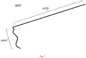
- the electrical wire A400 is required to connect with a water pump and a drive structure of the cleaning module 210. So the electrical wire A400 is divided into two sections.
- the first section A410 thereof is configured at the cleaning module 210 and the another section A420 thereof is configured at the filter screen rail module 220.
- the electrical wire A400 is configured along the cleaning module 210 and the filter screen rail module 220 to avoid that the space of other electrical wires is occupied for the arrangement of the electrical wire A400 on the chassis of the indoor unit. And an overly messy situation with other electrical wires is avoided. Thereby the arrangement of the electrical wire A400 that connecting the cleaning assembly 200 is simplified.
- the electrical wire A400 includes: a first electrical wire section A410 arranged at the cleaning module 210. And a second electrical wire section A420 arranged at the filter screen rail module 220; and
- the first electrical wire section A410 is arranged along a height direction of the cleaning module 210. And/or the second electrical wire section A420 is arranged along a length direction of the filter screen rail module 220.
- the cleaning module 210 and the filter screen rail module 220 are intersecting setting to fully utilize the internal space of the indoor unit. So that the first electrical wire section A410 is configured along the height direction of the cleaning module 210.
- the second electrical wire section A420 is configured along the length of the filter screen rail module 220, thus the length of the electrical wire A400 is minimized.
- the electrical wire A400 includes: a first electrical wire section A410 arranged at the cleaning module 210. And a second electrical wire section A420 arranged at the filter screen rail module 220.
- the first electrical wire section A410 is arranged at an outer side and a front side of the cleaning module 210.
- the indoor unit is hanged on a wall, and the front side of the cleaning module 210 is away from the wall. And the outer side of the cleaning module 210 is away from a heat exchanger of the indoor unit.
- the portion of the first electrical wire section A410 is configured on the outer side of cleaning module. And the remaining portion thereof is configured on the front side of cleaning module.
- the electrical wire A400 is also convenient for being integrally arranged.
- the side of the cleaning module 210 away from the wall is the front side thereof.
- the side thereof close to the wall is the rear side.
- the side of the heat exchanger close to the indoor unit is the inner side.
- the side of the heat exchanger away from the indoor unit is the outer side.
- the space corresponding to the front side of the cleaning module 210 is relatively abundant. And the front side space of the cleaning module 210 can be fully utilized.
- the first electrical wire section A410 is penetrated through the first clamping line member 211 and the second clamping line member 212.
- the first clamping line member 211 is a structure for forming a limit to the first electrical wire section A410.
- the various forms can be taken. For example, a restriction form of other electrical wires in the indoor unit is taken.
- the operation is the same as the first clamping line member 211.
- the first electrical wire section A410 is configured on the outer side and the front side of the cleaning module 210 by the arrangement of the first clamping line member 211 and the second clamping line member 212.
- the second clamping line member 212 is adjacent to the filter screen rail module 220, to force the first electrical wire section A410 and the second electrical wire section A420 to bend.
- the first electrical wire section A410 and the second electrical wire section A420 are formed in a bend shape, and are corresponded to the joint of the cleaning module 210 and the filter screen rail module 220.
- the electrical wire A400 isn't in a state of suspension for coming off the cleaning assembly 200. Thereby the electrical wire A400 is prevented from being squeezed when assembling the indoor unit.
- the first clamping line member 211 defines a first through hole 2111, and the first electrical wire section A410 is penetrated through the first through hole 2111; And/or, the second clamping line member 212 defines a second through hole 2121, and the first electrical wire section A410 is penetrated through the second through hole 2121.
- the first clamping line member 211 is configured as a closed annular structure, and is configured with a first through hole 2111. So that the first through hole 2111 is passed through by the first electrical wire section A410. That is, the first clamping line member 211 is passed through by the first electrical wire section A410. The first electrical wire section A410 is confined within the first through hole 2111 to prevent offset. The same operation is true for the second clamping line member 212, and the details are not repeated herein.
- the first electrical wire section A410 is configured along the outer side and the front side of the cleaning module 210. And thus the first electrical wire section A410 is in a bent state. And the first electrical wire section A410 is prevented from detaching by the arrangement of the first clamping line member 211 and the second clamping line member 212.
- a third clamping line member 213 at the front side of the cleaning module 210, and the second clamping line member 212 and the third clamping line member 213 are arranged at intervals from top to bottom along a height direction of the cleaning module 210. And the first electrical wire section A410 is further penetrated through the third clamping line member 213.
- the third clamping line member 213 is a structure for forming a limit to the first electrical wire section A410.
- the height direction of the cleaning module 210 is exemplified by the state in which the indoor unit is suspended from the wall.
- the cleaning module 210 is configured with a certain height.
- the first electrical wire section A410 located on the front side of the cleaning module 210 is effectively fixed to prevent the first electrical wire section A410 from being partially suspended by configuring at intervals the second card portion 212 and the third card portion 213.
- the third clamping line member 213 defines an electrical wire penetrating cavity 2131 and an opening 2132 communicating with the electrical wire penetrating cavity 2131, and a portion of the first electrical wire section A410 is inserted into the electrical wire penetrating cavity 2131 through the opening 2132.
- the third clamping line member 213 is not a closed annular structure and is configured with an electrical wire penetrating cavity 2131. A portion of the first electrical wire section A410 is inserted into the electrical wire penetrating cavity 2131 through the opening 2132. Such that the first electrical wire section A410 as a whole is in a state of passing through the third clamping line member 213.
- the portion of the first electrical wire section A410 is inserted into the third clamping line member 213. Thereby the assembly efficiency of the first electrical wire section A410 is improved. Moreover, since the first clamping line member 211 and the second clamping line member 212 have a closed annular structure, the first electrical wire section A410 is not easily separated from the first clamping line member 211 and the second clamping line member 212. The arrangement efficiency of the first electrical wire section A410 is improved on the premise of guaranting the fixing effect of the electrical wire section A410.
- the electrical wire A400 includes: a first electrical wire section A410 arranged at the cleaning module 210. And a second electrical wire section A420 arranged at the filter screen rail module 220.
- the second electrical wire section A420 is arranged at the front side of the filter screen rail module 220.
- the indoor unit is hanged on a wall.
- the front side of the filter screen rail module 220 is away from the wall.
- the utilization rate of space is also improved by the arrangement of the second electrical wire section A420 on the front side of the filter screen rail module 220.
- the length of the electrical wire is minimized.
- the fourth clamping line member 221 is a structure for forming a limit to the second electrical wire section A420. And thus various forms can be employed.
- the fourth electrical wire portion 221 is passed through the second electrical wire section A420, the second electrical wire section A420 is confined to the fourth electrical wire portion 221. Thereby the placement of the second electrical wire section A420 in the filter screen rail module 220 is achieved.
- the electrical wire A400 can be quickly configured in the cleaning assembly 200.
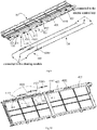
- the fourth clamping line member 221 defines: a electrical wire penetrating groove 2213 arranged along a length direction of the filter screen rail module 220. And an opening 2214 communicating with the electrical wire penetrating groove 2213.
- the electrical wire penetrating groove 2213 is a space for accommodating the second electrical wire section A420.
- the electrical wire penetrating groove 2213 is configured along the length direction of the filter screen rail module 220. So that the second electrical wire section A420 generally isn't configured with a bend.
- the second electrical wire section A420 is inserted into the electrical wire penetrating groove 2213 through the opening 2214. And the second electrical wire section A420 is in a state of passing through the fourth clamping line member 221. If the length of the electrical wire penetrating groove 2213 is long, the second electrical wire section A420 may be almost completely inserted into the electrical wire penetrating groove 2213. And the end of the second electrical wire section A420 is connected to the electric control box. If the length of the electrical wire penetrating groove 2213 is small, a portion of the second electrical wire sections A420 is inserted into the electrical wire penetrating groove.
- the fourth clamping line member 221 includes: a first limit element 2211, and a second limit element 2212.
- the number of the first limit element 2211 is at least two, and the two first limit elements 2211 and the second limit element 2212 are alternatively at intervals.
- the electrical wire penetrating groove 2213 and the electrical wire penetrating groove 2213 connected to the opening 2214 are defined between each first limit element 2211 and each second limit element 2212 and the electrical wire penetrating groove 2213 is connected to the opening 2214. And at least a part of the second electrical wire section A420 is inserted into the electrical wire penetrating groove 2213 through the opening 2214.
- the second limit elements 2212 are arranged along the length direction of the filter screen rail module 220. And at least a part of the second electrical wire section A420 is supported by the second limit element 2212. In the present embodiment, the second electrical wire section A420 is configured with a tendency to fall downward under the action of gravity. And the second limit element 2212 is configured along the length direction of the filter screen rail module 220. That is, the second limit element 2212 is configured with a certain length. At least a portion of the second electrical wire section A420 is supported by the second limit element 2212. So that the arrangement of the second electrical wire section A420 is more stable.
- the cleaning module 210 is connected to one end of the filter screen rail module 220, and the electrical control box is adjacent to another end of the filter screen rail module 220.
- the cleaning module 210 is located at one end of the filter screen rail module 220.
- the electrical control box is adjacent to another end of the filter screen rail module 220.
- the heat exchanger and the air duct assembly are located between the cleaning module 210 and the electrical control box.
- the indoor unit further includes a face frame (not shown) covering the cleaning assembly 200, and the cleaning assembly 200 is detachable from the face frame.
- the face frame is configured with an air inlet.
- the filter screen rail module 220 is located at the air inlet. And the air passes through the air opening, that is, the air passes through the filter screen rail module 220. And the air is filtered by the filter screen located in the filter screen rail module.
- the cleaning assembly is detachable relative to the face frame. Such that the cleaning assembly 200 is a separate functional assembly that the function of the cleaning assembly 200 can be tested before assembling the indoor unit.
- the electrical wire A400 is configured on the cleaning assembly 200 (the cleaning module 210 and the filter screen rail module 220).
- the arrangement of the electrical wire A400 can be realized before the assembly of the indoor unit.
- the cleaning assembly 200 can be prevented from being installed in the air conditioner.
- the arrangement of the electrical wire A400 is avoided to be realized only after the cleaning assembly 200 being installed in the chassis of the indoor unit. The assembly efficiency is further improved.
- the indoor unit includes:
- the air intake grill 300 is configured at the air inlet of the indoor unit.
- the filter screen is configured on the air intake grill 300.
- the air is circulated in the process of operating the conditioner indoor unit. And the air is filtered by the filter screen when passing through the air intake grill 300.
- the filter screen is easy to collect dust, batt or the like. So the filter screen is cleaned by setting the cleaning module.
- the cleaning module is located at one end of the air intake grill 300.
- the cleaning module includes a cleaning box, a cleaning structure, a driving structure, and an electric device.
- the electric device includes a motor, a water pump, a drain valve, or the like.
- the cleaning box is configured with a water cavity.
- the movement of the filter screen is driven by the driving structure which is driven by the motor.
- the cleaning structure is driven to clean the filter screen.
- the dirt on the filter screen is separated from the filter screen and dropped into the water cavity.
- the water is pumped by the water pump, and then that is mixed with the dirt to become the dirty water.
- the drain valve is controlled to dewater the dirty water.
- the electric device of the cleaning module needs to be electrically connected to the electric control box. So the first electrical wire 110 is necessary to be configured. One end of the first electrical wire 100 is connected with the electric device of the cleaning module. And another end of the first electrical wire is configured with the first connecting terminal B210.
- the electric control box and the cleaning module are configured at intervals. And the electric control box is configured at another end of the air intake grill 300.
- the electric control box is configured with a second electrical wire 120. And the end of the second electrical wire 120 is configured with a second connecting terminal B220.
- the first electrical wire 110 extends toward the electric control box. And the second electrical wire 120 extends toward the cleaning module.
- the first connecting terminal B210 and the second connecting terminal B220 are connected to be the connector B200.
- the connector B200 are fixed on the air intake grill 300. Since the control box is used as the control center of the indoor unit, which is needed to be electrically connected with other assemblys. That is, the area where the control box is located is configured with more connecting terminals.
- the second electrical wire 120 extends toward the cleaning module. That is, the second connecting terminal B220 is away from the electric control box. And the second connecting terminal B220 and the first connecting terminal B210 are connected to be the connector B200. That is, the first connecting terminal B210 is also away from the electric control box.
- the number of connecting terminal of the area where the electric control box is located is reduced.
- the messy connecting terminals are avoided. Thereby the management of electrical wire is facilitated.
- the electromagnetic interference is also reduced to some extent by reducing the number of connecting terminals in the area where the electric control box is located.
- the connector B200 is fixed on the air intake grill 300. So that the connector B200 is effectively fixed. But the connector B200 is connected by the first connecting terminal B210 and the second connecting terminal B220 (for example, the electrical connection between the electrical wire 110 and the second electrical wire 120 is achieved by slot-plug fit). In order to the first electrical wire 110, the first connecting terminal B210, the second connecting terminal B220, and the second electrical wire 120 are effectively fixed as a whole. In an embodiment of the present disclosure, referring to FIG. 1 and FIG. 2 , at least a part of the first electrical wire 110 is fixed on the air intake grill 300. And at least a part of the second electrical wire 120 is fixed on the air intake grill 300.
- first electrical wires 110 is fixed on the air intake grill 300.
- second electrical wires 120 is fixed on the air intake grill 300. So that the first electrical wires 110, the first connecting terminal B210, and the second connecting terminal B220 and the second electrical wire 120 are effectively fixed as a whole.
- the first electrical wire 110 includes a first electrical wire section and a second electrical wire section.
- the first electrical wire section of the first electrical wire 110 is taken out from the cleaning module.
- the second electrical wire section of the first electrical wire 110 is fixed on the air intake grill 300.
- the second electrical wire 120 includes the first electrical wire section and the second electrical wire section.
- the first electrical wire section of the second electrical wire 120 is taken out from the electric control box.
- the second electrical wire section of the second electrical wire 120 is fixed on the electric grille 300.
- the second electrical wire section of the first electrical wire 110 is configured with a first connecting terminal B210.
- the second electrical wire section of the second electrical wire 120 is configured with the second connecting terminal B220.
- the first connecting terminal B210 and the second connecting terminal B220 are connected to be connector B200.
- the connector B200 is fixed on a front side of the air intake grill 300, and at least the part of the first electrical wire 110 is fixed on the front side of the air intake grill 300. At least the part of the second electrical wire 120 is fixed on the front side of the air intake grill 300. And after the indoor unit is hanged on a wall, the front side of the air intake grill 300 is away from the wall, and a rear side of the air intake grill 300 is adjacent to the wall. In the present embodiment, when the indoor unit is assembled, the rear side of the air intake grill 300 abuts against the chassis. And the connector B200, at least a portion of the first electrical wire 110, and at least a portion of the second electrical wire 120 are fixed on the front side of the air intake grill 300. The installation work is easily performed for workers.
- the front side of the air intake grill 300 includes: a plurality of first limit elements 410 arranged at intervals along a length direction of the air intake grill 300, and a plurality of second limit elements 420, and each second limit element is arranged between each two adjacent first limit elements 410. And a receiving cavity 401 and an opening 402 communicating with the receiving cavity 401 are configured by each first limit element 410 and each second limit element 420.
- the connector B200 is inserted into the receiving cavity 401 through the opening 402.
- at least the part of the first electrical wire 110 is inserted into the receiving cavity 401 through the opening 402, and at least the part of the second electrical wire 120 is inserted into the receiving cavity 401 through the opening 402.
- the receiving cavity 401 extends along the length direction of the air intake grill 300. And the receiving cavity 401 and the opening 402 are the space defined by the first limit element 410 and the second limit element 420.
- the connector B200 After the connector B200, at least a portion of the first electrical wire 110, and at least a portion of the second electrical wire 120 are inserted into the receiving cavity 401.
- the connector B200, at least a portion of the first electrical wire 110 and at least a portion of the second electrical wire 120 are defined by the first limit element 410 and the second limit element 420 to avoid dropping of the electrical wire. Since the first electrical wire 110 and the second electrical wire 120 are integrally long after the docking.
- the opening 402 is configured in the embodiment. And the first electrical wire 110 and the second electrical wire 120 are integrated as a whole, and can be inserted into the receiving cavity 401 through the opening 402. Thus the installing work is more convenient.
- the first limit element 410 is extended along a thickness direction of the air intake grill 300, and the connector B200 is arranged on an inner side of the first limit element 410 which is adjacent to the receiving cavity 401.
- the first limit element 410 extends along the thickness direction of the air intake grill 300.
- the first limit element 410 extends in the up and down directions. So that the forward and backward movement of the entirety after being connected by the first electrical wire 110 and the second electrical wire 120 to the indoor unit is prevented.
- the inner side of the first limit element 410 is provided with at least two limiting ribs 411, the at least two limiting ribs 411 are arranged at intervals along the length direction of the air intake grill 300, and the connector B200 is arranged between the two limiting ribs 411.
- the connector B200 is placed between the two limiting ribs 411 by configuring the limiting rib 411. So that the connector B200 can be prevented from reciprocating along the length direction of the air intake grill 300. Thereby the connector B200 is better limited.
- the second limit element 420 is protruded toward the front of the air intake grill 300.
- the second limit element 420 is configured to support the first electrical wire 110 and the second electrical wire 120. After the first electrical wire 110 and the second electrical wire 110 being connected, which as a whole is inserted into the receiving cavity 401, and is supported by the second limit element 420 under the action of gravity.
- one first limit element 410 with the connector B200 on the inner side is defined as a connector limit element 4101, and remaining first limit elements 410 are defined as non-connector limit elements 4102.
- One second limit element 420 adjacent to the connector limit element 4101 is defined as a bearing element 421, and one second limit element 420 adjacent to the non-connector limit elements 4102 is defined as a supporting member 422.
- the bearing element 421 includes a first bearing element 4211 in a plate shape and arranged horizontally, and a second bearing element 4212 fixed with the first bearing element 4211, and at least the part of the first electrical wire 110 and at least the part of the second electrical wire 120 are supported by the first bearing element 4211.
- the supporting element 422 includes a first supporting part 4221 in a plate shape and arranged horizontally, and a second supporting part 4222 fixed with the first supporting element 4221, and at least the part of the first electrical wire 110 and at least the part of the second electrical wire 120 is supported by the first supporting element 4221.
- the connector B200 is needed to be inserted into the inner side of the connector limit element 4101 through the opening 402.
- the bearing element 421 is configured adjacent to the connector limit element 4101.
- the bearing element 421 is configured with the first bearing element 4211 that is in a plate shape and longitudinally configured.
- the contact area between the first bearing element 4211 and the electrical wire in the vicinity of the connector B200 is increased. So that the fixing of the connector B200 is more stable.
- the non-connector limit element 4102 does not need to be configured with the connector B200. Therefore, the supporting member 422 is configured which includes a first supporting member 4221 and a second supporting member 4222.
- the first supporting member 4221 is a plate shape and longitudinally configured. The operating space when embedding the electrical wire is increased. And the assembly is facilitated.
- the indoor unit includes a face frame (not shown).
- the face frame having an air inlet.
- the air intake grill 300 is arranged at the air inlet, and the air intake grill 300 is separable from the face frame.
- the air intake grill 300 is separable relative to the face frame. Therefore, before the indoor unit is assembled, the air intake grill 300 and the filter screen can be separately assembled to avoid the need to fit the face frame to assemble the filter screen.
- the present disclosure also provides an air conditioner including an air conditioner outdoor unit and the indoor unit of any one of the above embodiments.
- the indoor unit includes:
- the air conditioner outdoor unit may be an air conditioner outdoor unit in the prior art, which constitutes a refrigerant circulation with the indoor unit.
- the structure of the indoor unit of the present embodiment can be referred to the above embodiments as described. Since the structure of the indoor unit of the present embodiment adopts the technical solution of the above embodiment. At least the beneficial effects of the technical solutions of the above embodiments are obtained, and not be repeated here.
- the present disclosure also provides an air conditioner including an air conditioner outdoor unit and the indoor unit of any one of the above embodiments.
- the indoor unit includes:
- the specific structure of the indoor unit of the present embodiment can be referred to the above embodiments as described. Since the structure of the indoor unit of the present embodiment adopts the technical solution of the above embodiment. At least the beneficial effects of the technical solutions of the above embodiments are obtained, and not be repeated here.
- the refrigerant circulation is realized between the air conditioner outdoor unit and the indoor unit.
- the specific structure of the air conditioner outdoor unit can be referred to the air conditioner outdoor unit in the prior art, and not be repeated.
Landscapes
- Engineering & Computer Science (AREA)
- Chemical & Material Sciences (AREA)
- Combustion & Propulsion (AREA)
- Mechanical Engineering (AREA)
- General Engineering & Computer Science (AREA)
- Chemical Kinetics & Catalysis (AREA)
- Air Filters, Heat-Exchange Apparatuses, And Housings Of Air-Conditioning Units (AREA)
Applications Claiming Priority (4)
| Application Number | Priority Date | Filing Date | Title |
|---|---|---|---|
| CN201920179237.9U CN209541035U (zh) | 2019-01-31 | 2019-01-31 | 空调器室内机和空调器 |
| CN201910100987.7A CN109668217B (zh) | 2019-01-31 | 2019-01-31 | 空调器室内机和空调器 |
| CN201920321931.XU CN209672464U (zh) | 2019-03-13 | 2019-03-13 | 空调器室内机和空调器 |
| PCT/CN2019/112430 WO2020155675A1 (zh) | 2019-01-31 | 2019-10-22 | 空调器室内机和空调器 |
Publications (3)
| Publication Number | Publication Date |
|---|---|
| EP3715733A1 true EP3715733A1 (de) | 2020-09-30 |
| EP3715733A4 EP3715733A4 (de) | 2020-10-14 |
| EP3715733B1 EP3715733B1 (de) | 2023-08-30 |
Family
ID=70049809
Family Applications (1)
| Application Number | Title | Priority Date | Filing Date |
|---|---|---|---|
| EP19798156.6A Active EP3715733B1 (de) | 2019-01-31 | 2019-10-22 | Innenraumeinheit einer klimaanlage und klimaanlage |
Country Status (5)
| Country | Link |
|---|---|
| US (1) | US11982463B2 (de) |
| EP (1) | EP3715733B1 (de) |
| JP (1) | JP7130002B2 (de) |
| CA (1) | CA3128268C (de) |
| WO (1) | WO2020155675A1 (de) |
Families Citing this family (3)
| Publication number | Priority date | Publication date | Assignee | Title |
|---|---|---|---|---|
| WO2020155675A1 (zh) * | 2019-01-31 | 2020-08-06 | 广东美的制冷设备有限公司 | 空调器室内机和空调器 |
| US12480667B2 (en) * | 2021-05-24 | 2025-11-25 | Lg Electronics Inc. | Air-conditioning system |
| US12474068B2 (en) * | 2021-05-24 | 2025-11-18 | Lg Electronics Inc. | Air-conditioning system |
Family Cites Families (37)
| Publication number | Priority date | Publication date | Assignee | Title |
|---|---|---|---|---|
| JP4110375B2 (ja) | 2002-06-27 | 2008-07-02 | 株式会社富士通ゼネラル | 空気調和機 |
| JP4591683B2 (ja) * | 2004-09-03 | 2010-12-01 | 株式会社富士通ゼネラル | 空気調和機 |
| KR20080014473A (ko) * | 2006-08-11 | 2008-02-14 | 엘지전자 주식회사 | 공기조화기 |
| KR20080055461A (ko) * | 2006-12-15 | 2008-06-19 | 엘지전자 주식회사 | 공기조화기 |
| CN101606028B (zh) * | 2007-02-09 | 2011-04-13 | 大金工业株式会社 | 空调装置的室内机组 |
| CN101290152B (zh) * | 2007-04-18 | 2010-05-26 | 海尔集团公司 | 过滤网自清洁装置 |
| CN101576287B (zh) | 2008-05-09 | 2013-03-27 | 乐金电子(天津)电器有限公司 | 空调器 |
| CN101581471B (zh) | 2008-05-13 | 2013-03-27 | 乐金电子(天津)电器有限公司 | 空调器 |
| JP5020208B2 (ja) | 2008-09-19 | 2012-09-05 | 三菱電機株式会社 | フィルターの清掃装置及びこれを搭載した空気調和機 |
| JP5108120B2 (ja) * | 2011-01-11 | 2012-12-26 | シャープ株式会社 | フィルタ保持装置、フィルタ清掃装置および空気調和機 |
| JP2015188851A (ja) * | 2014-03-28 | 2015-11-02 | 株式会社富士通ゼネラル | 電気集塵装置および空気調和機 |
| CN203848475U (zh) | 2014-05-13 | 2014-09-24 | 杨元清 | 一种自清洁滤网的空调 |
| JP2016017670A (ja) | 2014-07-07 | 2016-02-01 | 三菱電機株式会社 | 接続電線固定装置、この接続電線固定装置を用いた電装箱、および空気調和機の室内機 |
| CN107250675B (zh) * | 2015-03-06 | 2019-10-11 | 三菱电机株式会社 | 空调机 |
| WO2016143004A1 (ja) * | 2015-03-06 | 2016-09-15 | 三菱電機株式会社 | 空気清浄装置及び機器 |
| JP6456483B2 (ja) * | 2015-04-17 | 2019-01-23 | 三菱電機株式会社 | 空気調和機の室内機 |
| CN204853892U (zh) | 2015-07-27 | 2015-12-09 | 海信(山东)空调有限公司 | 一种具有过滤网清洁装置的空调器 |
| CN105089465B (zh) * | 2015-09-14 | 2017-06-20 | 青岛兰道尔空气动力工程有限公司 | 一种通风净化器 |
| CN107923633B (zh) * | 2016-01-06 | 2020-03-06 | 三菱电机株式会社 | 空调的室内机 |
| KR102414268B1 (ko) * | 2016-07-22 | 2022-06-29 | 엘지전자 주식회사 | 공기조화기 |
| CN113007808A (zh) * | 2017-01-25 | 2021-06-22 | 珠海格力电器股份有限公司 | 一种壁挂式空调室内机及空调器 |
| JP2019007653A (ja) | 2017-06-22 | 2019-01-17 | パナソニックIpマネジメント株式会社 | 空気調和機 |
| CN206959172U (zh) | 2017-07-21 | 2018-02-02 | 广东美的制冷设备有限公司 | 空调室内机及有其的空调器 |
| CN207137575U (zh) | 2017-07-21 | 2018-03-27 | 广东美的制冷设备有限公司 | 空调过滤网的除尘装置及空调室内机 |
| CN207268535U (zh) | 2017-07-25 | 2018-04-24 | 青岛海尔空调器有限总公司 | 一种立式空调的过滤模组的安装结构及进风栅 |
| CN107940637A (zh) * | 2017-11-05 | 2018-04-20 | 佛山市因诺威特科技有限公司 | 可自动调控节能环保型医用净化空调设备 |
| KR102661384B1 (ko) * | 2018-03-07 | 2024-04-26 | 엘지전자 주식회사 | 공기조화기의 실내기 |
| CN108488926B (zh) | 2018-06-01 | 2024-06-25 | 广东美的制冷设备有限公司 | 空调器 |
| CN108767766B (zh) | 2018-06-29 | 2024-07-19 | 广东美的制冷设备有限公司 | 家用电器的走线装置及具有其的空调器 |
| CN109442621B (zh) * | 2018-11-02 | 2020-09-08 | 苏州德粤通风机电设备有限公司 | 一种工业用空气净化装置及其工作方法 |
| CN109668217B (zh) | 2019-01-31 | 2024-04-26 | 广东美的制冷设备有限公司 | 空调器室内机和空调器 |
| CN209541035U (zh) | 2019-01-31 | 2019-10-25 | 广东美的制冷设备有限公司 | 空调器室内机和空调器 |
| WO2020155675A1 (zh) * | 2019-01-31 | 2020-08-06 | 广东美的制冷设备有限公司 | 空调器室内机和空调器 |
| KR102433659B1 (ko) * | 2020-05-04 | 2022-08-17 | 엘지전자 주식회사 | 공기청정기 |
| CN111578385B (zh) * | 2020-05-09 | 2021-11-23 | 青岛海尔空调器有限总公司 | 用于空调器过滤网自清洁的结构及空调器 |
| CN111578386B (zh) * | 2020-05-09 | 2021-10-29 | 青岛海尔空调器有限总公司 | 用于空调器过滤网自清洁的结构及空调器 |
| KR102471335B1 (ko) * | 2020-06-03 | 2022-11-25 | 엘지전자 주식회사 | 공기청정기 |
-
2019
- 2019-10-22 WO PCT/CN2019/112430 patent/WO2020155675A1/zh not_active Ceased
- 2019-10-22 US US17/427,028 patent/US11982463B2/en active Active
- 2019-10-22 CA CA3128268A patent/CA3128268C/en active Active
- 2019-10-22 JP JP2019564429A patent/JP7130002B2/ja active Active
- 2019-10-22 EP EP19798156.6A patent/EP3715733B1/de active Active
Also Published As
| Publication number | Publication date |
|---|---|
| JP2021515166A (ja) | 2021-06-17 |
| EP3715733A4 (de) | 2020-10-14 |
| WO2020155675A1 (zh) | 2020-08-06 |
| EP3715733B1 (de) | 2023-08-30 |
| CA3128268C (en) | 2023-08-01 |
| US20220099334A1 (en) | 2022-03-31 |
| US11982463B2 (en) | 2024-05-14 |
| CA3128268A1 (en) | 2020-08-06 |
| JP7130002B2 (ja) | 2022-09-02 |
Similar Documents
| Publication | Publication Date | Title |
|---|---|---|
| EP3715733B1 (de) | Innenraumeinheit einer klimaanlage und klimaanlage | |
| EP3182023B1 (de) | Klimaanlage | |
| EP2056028A2 (de) | Außenraumeinheit für Klimaanlage | |
| EP2040008A2 (de) | Außeneinheit für eine Klimaanlage | |
| JP3259719B2 (ja) | 空気調和機 | |
| KR20040082957A (ko) | 벽걸이형 공기 조화 장치 | |
| CN109668217B (zh) | 空调器室内机和空调器 | |
| CN209541035U (zh) | 空调器室内机和空调器 | |
| JP2007248011A (ja) | 空気調和機 | |
| CN214038678U (zh) | 空调设备 | |
| CN212777841U (zh) | 一种空调的电控盒 | |
| CN209672464U (zh) | 空调器室内机和空调器 | |
| CN221690713U (zh) | 空气炸锅 | |
| CN220457780U (zh) | 空调柜体及列间空调 | |
| CN222911801U (zh) | 空调室内机 | |
| CN214206252U (zh) | 一种电控柜的散热装置 | |
| CN224065601U (zh) | 机壳组件、室外机和暖通设备 | |
| CN220206027U (zh) | 前面板及空调室内机 | |
| CN218919728U (zh) | 一种变频器电气控制柜 | |
| CN211182832U (zh) | 一种写字楼中央空调专用配电柜 | |
| CN220798713U (zh) | 模组安装箱、模块化led显示装置及拼装显示屏 | |
| CN224003824U (zh) | 窗式空调器 | |
| CN218627099U (zh) | 一种电控结构及空调室外机 | |
| CN111089336A (zh) | 一种空调净化组件以及空调器组件 | |
| CN216048075U (zh) | 安装组件、室外机和热泵设备 |
Legal Events
| Date | Code | Title | Description |
|---|---|---|---|
| STAA | Information on the status of an ep patent application or granted ep patent |
Free format text: STATUS: UNKNOWN |
|
| STAA | Information on the status of an ep patent application or granted ep patent |
Free format text: STATUS: THE INTERNATIONAL PUBLICATION HAS BEEN MADE |
|
| PUAI | Public reference made under article 153(3) epc to a published international application that has entered the european phase |
Free format text: ORIGINAL CODE: 0009012 |
|
| STAA | Information on the status of an ep patent application or granted ep patent |
Free format text: STATUS: REQUEST FOR EXAMINATION WAS MADE |
|
| 17P | Request for examination filed |
Effective date: 20191114 |
|
| AK | Designated contracting states |
Kind code of ref document: A1 Designated state(s): AL AT BE BG CH CY CZ DE DK EE ES FI FR GB GR HR HU IE IS IT LI LT LU LV MC MK MT NL NO PL PT RO RS SE SI SK SM TR |
|
| AX | Request for extension of the european patent |
Extension state: BA ME |
|
| A4 | Supplementary search report drawn up and despatched |
Effective date: 20200911 |
|
| RIC1 | Information provided on ipc code assigned before grant |
Ipc: B01D 41/04 20060101ALI20200907BHEP Ipc: F24F 1/0073 20190101AFI20200907BHEP Ipc: F24F 13/20 20060101ALN20200907BHEP Ipc: F24F 13/28 20060101ALI20200907BHEP Ipc: F24F 1/0057 20190101ALI20200907BHEP |
|
| RAP3 | Party data changed (applicant data changed or rights of an application transferred) |
Owner name: MIDEA GROUP CO., LTD. Owner name: GD MIDEA AIR-CONDITIONING EQUIPMENT CO., LTD. |
|
| STAA | Information on the status of an ep patent application or granted ep patent |
Free format text: STATUS: EXAMINATION IS IN PROGRESS |
|
| 17Q | First examination report despatched |
Effective date: 20220329 |
|
| DAV | Request for validation of the european patent (deleted) | ||
| DAX | Request for extension of the european patent (deleted) | ||
| GRAP | Despatch of communication of intention to grant a patent |
Free format text: ORIGINAL CODE: EPIDOSNIGR1 |
|
| STAA | Information on the status of an ep patent application or granted ep patent |
Free format text: STATUS: GRANT OF PATENT IS INTENDED |
|
| RIC1 | Information provided on ipc code assigned before grant |
Ipc: F24F 13/20 20060101ALN20230522BHEP Ipc: F24F 1/0057 20190101ALI20230522BHEP Ipc: F24F 13/28 20060101ALI20230522BHEP Ipc: B01D 41/04 20060101ALI20230522BHEP Ipc: F24F 1/0073 20190101AFI20230522BHEP |
|
| INTG | Intention to grant announced |
Effective date: 20230613 |
|
| GRAS | Grant fee paid |
Free format text: ORIGINAL CODE: EPIDOSNIGR3 |
|
| GRAA | (expected) grant |
Free format text: ORIGINAL CODE: 0009210 |
|
| STAA | Information on the status of an ep patent application or granted ep patent |
Free format text: STATUS: THE PATENT HAS BEEN GRANTED |
|
| AK | Designated contracting states |
Kind code of ref document: B1 Designated state(s): AL AT BE BG CH CY CZ DE DK EE ES FI FR GB GR HR HU IE IS IT LI LT LU LV MC MK MT NL NO PL PT RO RS SE SI SK SM TR |
|
| REG | Reference to a national code |
Ref country code: GB Ref legal event code: FG4D |
|
| REG | Reference to a national code |
Ref country code: CH Ref legal event code: EP |
|
| REG | Reference to a national code |
Ref country code: DE Ref legal event code: R096 Ref document number: 602019036278 Country of ref document: DE |
|
| REG | Reference to a national code |
Ref country code: IE Ref legal event code: FG4D |
|
| REG | Reference to a national code |
Ref country code: LT Ref legal event code: MG9D |
|
| REG | Reference to a national code |
Ref country code: NL Ref legal event code: MP Effective date: 20230830 |
|
| REG | Reference to a national code |
Ref country code: AT Ref legal event code: MK05 Ref document number: 1605896 Country of ref document: AT Kind code of ref document: T Effective date: 20230830 |
|
| PG25 | Lapsed in a contracting state [announced via postgrant information from national office to epo] |
Ref country code: GR Free format text: LAPSE BECAUSE OF FAILURE TO SUBMIT A TRANSLATION OF THE DESCRIPTION OR TO PAY THE FEE WITHIN THE PRESCRIBED TIME-LIMIT Effective date: 20231201 |
|
| PG25 | Lapsed in a contracting state [announced via postgrant information from national office to epo] |
Ref country code: IS Free format text: LAPSE BECAUSE OF FAILURE TO SUBMIT A TRANSLATION OF THE DESCRIPTION OR TO PAY THE FEE WITHIN THE PRESCRIBED TIME-LIMIT Effective date: 20231230 |
|
| PG25 | Lapsed in a contracting state [announced via postgrant information from national office to epo] |
Ref country code: SE Free format text: LAPSE BECAUSE OF FAILURE TO SUBMIT A TRANSLATION OF THE DESCRIPTION OR TO PAY THE FEE WITHIN THE PRESCRIBED TIME-LIMIT Effective date: 20230830 Ref country code: RS Free format text: LAPSE BECAUSE OF FAILURE TO SUBMIT A TRANSLATION OF THE DESCRIPTION OR TO PAY THE FEE WITHIN THE PRESCRIBED TIME-LIMIT Effective date: 20230830 Ref country code: NO Free format text: LAPSE BECAUSE OF FAILURE TO SUBMIT A TRANSLATION OF THE DESCRIPTION OR TO PAY THE FEE WITHIN THE PRESCRIBED TIME-LIMIT Effective date: 20231130 Ref country code: LV Free format text: LAPSE BECAUSE OF FAILURE TO SUBMIT A TRANSLATION OF THE DESCRIPTION OR TO PAY THE FEE WITHIN THE PRESCRIBED TIME-LIMIT Effective date: 20230830 Ref country code: LT Free format text: LAPSE BECAUSE OF FAILURE TO SUBMIT A TRANSLATION OF THE DESCRIPTION OR TO PAY THE FEE WITHIN THE PRESCRIBED TIME-LIMIT Effective date: 20230830 Ref country code: IS Free format text: LAPSE BECAUSE OF FAILURE TO SUBMIT A TRANSLATION OF THE DESCRIPTION OR TO PAY THE FEE WITHIN THE PRESCRIBED TIME-LIMIT Effective date: 20231230 Ref country code: HR Free format text: LAPSE BECAUSE OF FAILURE TO SUBMIT A TRANSLATION OF THE DESCRIPTION OR TO PAY THE FEE WITHIN THE PRESCRIBED TIME-LIMIT Effective date: 20230830 Ref country code: GR Free format text: LAPSE BECAUSE OF FAILURE TO SUBMIT A TRANSLATION OF THE DESCRIPTION OR TO PAY THE FEE WITHIN THE PRESCRIBED TIME-LIMIT Effective date: 20231201 Ref country code: FI Free format text: LAPSE BECAUSE OF FAILURE TO SUBMIT A TRANSLATION OF THE DESCRIPTION OR TO PAY THE FEE WITHIN THE PRESCRIBED TIME-LIMIT Effective date: 20230830 Ref country code: AT Free format text: LAPSE BECAUSE OF FAILURE TO SUBMIT A TRANSLATION OF THE DESCRIPTION OR TO PAY THE FEE WITHIN THE PRESCRIBED TIME-LIMIT Effective date: 20230830 |
|
| PG25 | Lapsed in a contracting state [announced via postgrant information from national office to epo] |
Ref country code: PL Free format text: LAPSE BECAUSE OF FAILURE TO SUBMIT A TRANSLATION OF THE DESCRIPTION OR TO PAY THE FEE WITHIN THE PRESCRIBED TIME-LIMIT Effective date: 20230830 Ref country code: NL Free format text: LAPSE BECAUSE OF FAILURE TO SUBMIT A TRANSLATION OF THE DESCRIPTION OR TO PAY THE FEE WITHIN THE PRESCRIBED TIME-LIMIT Effective date: 20230830 |
|
| PG25 | Lapsed in a contracting state [announced via postgrant information from national office to epo] |
Ref country code: ES Free format text: LAPSE BECAUSE OF FAILURE TO SUBMIT A TRANSLATION OF THE DESCRIPTION OR TO PAY THE FEE WITHIN THE PRESCRIBED TIME-LIMIT Effective date: 20230830 |
|
| PG25 | Lapsed in a contracting state [announced via postgrant information from national office to epo] |
Ref country code: SM Free format text: LAPSE BECAUSE OF FAILURE TO SUBMIT A TRANSLATION OF THE DESCRIPTION OR TO PAY THE FEE WITHIN THE PRESCRIBED TIME-LIMIT Effective date: 20230830 Ref country code: RO Free format text: LAPSE BECAUSE OF FAILURE TO SUBMIT A TRANSLATION OF THE DESCRIPTION OR TO PAY THE FEE WITHIN THE PRESCRIBED TIME-LIMIT Effective date: 20230830 Ref country code: ES Free format text: LAPSE BECAUSE OF FAILURE TO SUBMIT A TRANSLATION OF THE DESCRIPTION OR TO PAY THE FEE WITHIN THE PRESCRIBED TIME-LIMIT Effective date: 20230830 Ref country code: EE Free format text: LAPSE BECAUSE OF FAILURE TO SUBMIT A TRANSLATION OF THE DESCRIPTION OR TO PAY THE FEE WITHIN THE PRESCRIBED TIME-LIMIT Effective date: 20230830 Ref country code: DK Free format text: LAPSE BECAUSE OF FAILURE TO SUBMIT A TRANSLATION OF THE DESCRIPTION OR TO PAY THE FEE WITHIN THE PRESCRIBED TIME-LIMIT Effective date: 20230830 Ref country code: CZ Free format text: LAPSE BECAUSE OF FAILURE TO SUBMIT A TRANSLATION OF THE DESCRIPTION OR TO PAY THE FEE WITHIN THE PRESCRIBED TIME-LIMIT Effective date: 20230830 Ref country code: PT Free format text: LAPSE BECAUSE OF FAILURE TO SUBMIT A TRANSLATION OF THE DESCRIPTION OR TO PAY THE FEE WITHIN THE PRESCRIBED TIME-LIMIT Effective date: 20240102 Ref country code: SK Free format text: LAPSE BECAUSE OF FAILURE TO SUBMIT A TRANSLATION OF THE DESCRIPTION OR TO PAY THE FEE WITHIN THE PRESCRIBED TIME-LIMIT Effective date: 20230830 |
|
| PG25 | Lapsed in a contracting state [announced via postgrant information from national office to epo] |
Ref country code: IT Free format text: LAPSE BECAUSE OF FAILURE TO SUBMIT A TRANSLATION OF THE DESCRIPTION OR TO PAY THE FEE WITHIN THE PRESCRIBED TIME-LIMIT Effective date: 20230830 Ref country code: MC Free format text: LAPSE BECAUSE OF FAILURE TO SUBMIT A TRANSLATION OF THE DESCRIPTION OR TO PAY THE FEE WITHIN THE PRESCRIBED TIME-LIMIT Effective date: 20230830 |
|
| REG | Reference to a national code |
Ref country code: CH Ref legal event code: PL |
|
| REG | Reference to a national code |
Ref country code: DE Ref legal event code: R097 Ref document number: 602019036278 Country of ref document: DE |
|
| REG | Reference to a national code |
Ref country code: BE Ref legal event code: MM Effective date: 20231031 |
|
| PG25 | Lapsed in a contracting state [announced via postgrant information from national office to epo] |
Ref country code: LU Free format text: LAPSE BECAUSE OF NON-PAYMENT OF DUE FEES Effective date: 20231022 |
|
| PG25 | Lapsed in a contracting state [announced via postgrant information from national office to epo] |
Ref country code: LU Free format text: LAPSE BECAUSE OF NON-PAYMENT OF DUE FEES Effective date: 20231022 |
|
| PLBE | No opposition filed within time limit |
Free format text: ORIGINAL CODE: 0009261 |
|
| STAA | Information on the status of an ep patent application or granted ep patent |
Free format text: STATUS: NO OPPOSITION FILED WITHIN TIME LIMIT |
|
| PG25 | Lapsed in a contracting state [announced via postgrant information from national office to epo] |
Ref country code: CH Free format text: LAPSE BECAUSE OF NON-PAYMENT OF DUE FEES Effective date: 20231031 |
|
| GBPC | Gb: european patent ceased through non-payment of renewal fee |
Effective date: 20231130 |
|
| PG25 | Lapsed in a contracting state [announced via postgrant information from national office to epo] |
Ref country code: FR Free format text: LAPSE BECAUSE OF NON-PAYMENT OF DUE FEES Effective date: 20231030 Ref country code: CH Free format text: LAPSE BECAUSE OF NON-PAYMENT OF DUE FEES Effective date: 20231031 Ref country code: SI Free format text: LAPSE BECAUSE OF FAILURE TO SUBMIT A TRANSLATION OF THE DESCRIPTION OR TO PAY THE FEE WITHIN THE PRESCRIBED TIME-LIMIT Effective date: 20230830 |
|
| 26N | No opposition filed |
Effective date: 20240603 |
|
| PG25 | Lapsed in a contracting state [announced via postgrant information from national office to epo] |
Ref country code: BE Free format text: LAPSE BECAUSE OF NON-PAYMENT OF DUE FEES Effective date: 20231031 |
|
| PG25 | Lapsed in a contracting state [announced via postgrant information from national office to epo] |
Ref country code: IE Free format text: LAPSE BECAUSE OF NON-PAYMENT OF DUE FEES Effective date: 20231022 |
|
| PG25 | Lapsed in a contracting state [announced via postgrant information from national office to epo] |
Ref country code: GB Free format text: LAPSE BECAUSE OF NON-PAYMENT OF DUE FEES Effective date: 20231130 |
|
| PG25 | Lapsed in a contracting state [announced via postgrant information from national office to epo] |
Ref country code: IE Free format text: LAPSE BECAUSE OF NON-PAYMENT OF DUE FEES Effective date: 20231022 Ref country code: GB Free format text: LAPSE BECAUSE OF NON-PAYMENT OF DUE FEES Effective date: 20231130 |
|
| PG25 | Lapsed in a contracting state [announced via postgrant information from national office to epo] |
Ref country code: BG Free format text: LAPSE BECAUSE OF FAILURE TO SUBMIT A TRANSLATION OF THE DESCRIPTION OR TO PAY THE FEE WITHIN THE PRESCRIBED TIME-LIMIT Effective date: 20230830 |
|
| PG25 | Lapsed in a contracting state [announced via postgrant information from national office to epo] |
Ref country code: BG Free format text: LAPSE BECAUSE OF FAILURE TO SUBMIT A TRANSLATION OF THE DESCRIPTION OR TO PAY THE FEE WITHIN THE PRESCRIBED TIME-LIMIT Effective date: 20230830 |
|
| PGFP | Annual fee paid to national office [announced via postgrant information from national office to epo] |
Ref country code: DE Payment date: 20241022 Year of fee payment: 6 |
|
| PG25 | Lapsed in a contracting state [announced via postgrant information from national office to epo] |
Ref country code: CY Free format text: LAPSE BECAUSE OF FAILURE TO SUBMIT A TRANSLATION OF THE DESCRIPTION OR TO PAY THE FEE WITHIN THE PRESCRIBED TIME-LIMIT; INVALID AB INITIO Effective date: 20191022 |
|
| PG25 | Lapsed in a contracting state [announced via postgrant information from national office to epo] |
Ref country code: HU Free format text: LAPSE BECAUSE OF FAILURE TO SUBMIT A TRANSLATION OF THE DESCRIPTION OR TO PAY THE FEE WITHIN THE PRESCRIBED TIME-LIMIT; INVALID AB INITIO Effective date: 20191022 |
|
| PG25 | Lapsed in a contracting state [announced via postgrant information from national office to epo] |
Ref country code: TR Free format text: LAPSE BECAUSE OF FAILURE TO SUBMIT A TRANSLATION OF THE DESCRIPTION OR TO PAY THE FEE WITHIN THE PRESCRIBED TIME-LIMIT Effective date: 20230830 |