EP3715760B1 - Dérivation d'échangeur de chaleur - Google Patents
Dérivation d'échangeur de chaleur Download PDFInfo
- Publication number
- EP3715760B1 EP3715760B1 EP20153957.4A EP20153957A EP3715760B1 EP 3715760 B1 EP3715760 B1 EP 3715760B1 EP 20153957 A EP20153957 A EP 20153957A EP 3715760 B1 EP3715760 B1 EP 3715760B1
- Authority
- EP
- European Patent Office
- Prior art keywords
- refrigerant
- pipes
- header pipe
- header
- flat
- Prior art date
- Legal status (The legal status is an assumption and is not a legal conclusion. Google has not performed a legal analysis and makes no representation as to the accuracy of the status listed.)
- Active
Links
Images


Classifications
-
- F—MECHANICAL ENGINEERING; LIGHTING; HEATING; WEAPONS; BLASTING
- F25—REFRIGERATION OR COOLING; COMBINED HEATING AND REFRIGERATION SYSTEMS; HEAT PUMP SYSTEMS; MANUFACTURE OR STORAGE OF ICE; LIQUEFACTION SOLIDIFICATION OF GASES
- F25B—REFRIGERATION MACHINES, PLANTS OR SYSTEMS; COMBINED HEATING AND REFRIGERATION SYSTEMS; HEAT PUMP SYSTEMS
- F25B41/00—Fluid-circulation arrangements
-
- F—MECHANICAL ENGINEERING; LIGHTING; HEATING; WEAPONS; BLASTING
- F28—HEAT EXCHANGE IN GENERAL
- F28D—HEAT-EXCHANGE APPARATUS, NOT PROVIDED FOR IN ANOTHER SUBCLASS, IN WHICH THE HEAT-EXCHANGE MEDIA DO NOT COME INTO DIRECT CONTACT
- F28D1/00—Heat-exchange apparatus having stationary conduit assemblies for one heat-exchange medium only, the media being in contact with different sides of the conduit wall, in which the other heat-exchange medium is a large body of fluid, e.g. domestic or motor car radiators
- F28D1/02—Heat-exchange apparatus having stationary conduit assemblies for one heat-exchange medium only, the media being in contact with different sides of the conduit wall, in which the other heat-exchange medium is a large body of fluid, e.g. domestic or motor car radiators with heat-exchange conduits immersed in the body of fluid
- F28D1/04—Heat-exchange apparatus having stationary conduit assemblies for one heat-exchange medium only, the media being in contact with different sides of the conduit wall, in which the other heat-exchange medium is a large body of fluid, e.g. domestic or motor car radiators with heat-exchange conduits immersed in the body of fluid with tubular conduits
- F28D1/053—Heat-exchange apparatus having stationary conduit assemblies for one heat-exchange medium only, the media being in contact with different sides of the conduit wall, in which the other heat-exchange medium is a large body of fluid, e.g. domestic or motor car radiators with heat-exchange conduits immersed in the body of fluid with tubular conduits the conduits being straight
- F28D1/0535—Heat-exchange apparatus having stationary conduit assemblies for one heat-exchange medium only, the media being in contact with different sides of the conduit wall, in which the other heat-exchange medium is a large body of fluid, e.g. domestic or motor car radiators with heat-exchange conduits immersed in the body of fluid with tubular conduits the conduits being straight the conduits having a non-circular cross-section
- F28D1/05366—Assemblies of conduits connected to common headers, e.g. core type radiators
- F28D1/05375—Assemblies of conduits connected to common headers, e.g. core type radiators with particular pattern of flow, e.g. change of flow direction
-
- F—MECHANICAL ENGINEERING; LIGHTING; HEATING; WEAPONS; BLASTING
- F28—HEAT EXCHANGE IN GENERAL
- F28D—HEAT-EXCHANGE APPARATUS, NOT PROVIDED FOR IN ANOTHER SUBCLASS, IN WHICH THE HEAT-EXCHANGE MEDIA DO NOT COME INTO DIRECT CONTACT
- F28D1/00—Heat-exchange apparatus having stationary conduit assemblies for one heat-exchange medium only, the media being in contact with different sides of the conduit wall, in which the other heat-exchange medium is a large body of fluid, e.g. domestic or motor car radiators
- F28D1/02—Heat-exchange apparatus having stationary conduit assemblies for one heat-exchange medium only, the media being in contact with different sides of the conduit wall, in which the other heat-exchange medium is a large body of fluid, e.g. domestic or motor car radiators with heat-exchange conduits immersed in the body of fluid
- F28D1/04—Heat-exchange apparatus having stationary conduit assemblies for one heat-exchange medium only, the media being in contact with different sides of the conduit wall, in which the other heat-exchange medium is a large body of fluid, e.g. domestic or motor car radiators with heat-exchange conduits immersed in the body of fluid with tubular conduits
- F28D1/047—Heat-exchange apparatus having stationary conduit assemblies for one heat-exchange medium only, the media being in contact with different sides of the conduit wall, in which the other heat-exchange medium is a large body of fluid, e.g. domestic or motor car radiators with heat-exchange conduits immersed in the body of fluid with tubular conduits the conduits being bent, e.g. in a serpentine or zig-zag
- F28D1/0471—Heat-exchange apparatus having stationary conduit assemblies for one heat-exchange medium only, the media being in contact with different sides of the conduit wall, in which the other heat-exchange medium is a large body of fluid, e.g. domestic or motor car radiators with heat-exchange conduits immersed in the body of fluid with tubular conduits the conduits being bent, e.g. in a serpentine or zig-zag the conduits having a non-circular cross-section
-
- F—MECHANICAL ENGINEERING; LIGHTING; HEATING; WEAPONS; BLASTING
- F28—HEAT EXCHANGE IN GENERAL
- F28F—DETAILS OF HEAT-EXCHANGE AND HEAT-TRANSFER APPARATUS, OF GENERAL APPLICATION
- F28F9/00—Casings; Header boxes; Auxiliary supports for elements; Auxiliary members within casings
- F28F9/02—Header boxes; End plates
- F28F9/0202—Header boxes having their inner space divided by partitions
- F28F9/0204—Header boxes having their inner space divided by partitions for elongated header box, e.g. with transversal and longitudinal partitions
-
- F—MECHANICAL ENGINEERING; LIGHTING; HEATING; WEAPONS; BLASTING
- F28—HEAT EXCHANGE IN GENERAL
- F28F—DETAILS OF HEAT-EXCHANGE AND HEAT-TRANSFER APPARATUS, OF GENERAL APPLICATION
- F28F9/00—Casings; Header boxes; Auxiliary supports for elements; Auxiliary members within casings
- F28F9/02—Header boxes; End plates
- F28F9/026—Header boxes; End plates with static flow control means, e.g. with means for uniformly distributing heat exchange media into conduits
- F28F9/0278—Header boxes; End plates with static flow control means, e.g. with means for uniformly distributing heat exchange media into conduits in the form of stacked distribution plates or perforated plates arranged over end plates
-
- F—MECHANICAL ENGINEERING; LIGHTING; HEATING; WEAPONS; BLASTING
- F25—REFRIGERATION OR COOLING; COMBINED HEATING AND REFRIGERATION SYSTEMS; HEAT PUMP SYSTEMS; MANUFACTURE OR STORAGE OF ICE; LIQUEFACTION SOLIDIFICATION OF GASES
- F25B—REFRIGERATION MACHINES, PLANTS OR SYSTEMS; COMBINED HEATING AND REFRIGERATION SYSTEMS; HEAT PUMP SYSTEMS
- F25B2313/00—Compression machines, plants or systems with reversible cycle not otherwise provided for
- F25B2313/005—Outdoor unit expansion valves
-
- F—MECHANICAL ENGINEERING; LIGHTING; HEATING; WEAPONS; BLASTING
- F28—HEAT EXCHANGE IN GENERAL
- F28D—HEAT-EXCHANGE APPARATUS, NOT PROVIDED FOR IN ANOTHER SUBCLASS, IN WHICH THE HEAT-EXCHANGE MEDIA DO NOT COME INTO DIRECT CONTACT
- F28D21/00—Heat-exchange apparatus not covered by any of the groups F28D1/00 - F28D20/00
- F28D2021/0019—Other heat exchangers for particular applications; Heat exchange systems not otherwise provided for
- F28D2021/0068—Other heat exchangers for particular applications; Heat exchange systems not otherwise provided for for refrigerant cycles
Definitions
- the present invention relates to a heat exchanger which is constituted by a pair of header pipes and a plurality of flat pipes having a plurality of refrigerant flow paths to execute heat exchange between air flowing in the plurality of flat pipes and refrigerant flowing in the refrigerant flow paths of the flat pipes.
- a heat exchanger which is constituted by a pair of header pipes facing right and left in a horizontal direction, a plurality of flat pipes having a plurality of refrigerant flow paths and a heat-transfer fin provided between the flat pipes to execute heat exchange between air flowing in the plurality of flat pipes and refrigerant flowing in the refrigerant flow paths of the flat pipes.
- a heat exchanger shunt in which the plurality of flat pipes are further grouped into groups of several flat pipes and each group constitutes a one-turn heat exchange section where one of the pair of header pipes flows refrigerant to the other, and an upper limit and a lower limit of the number of flat pipes constituting the one-turn heat exchange section are determined by a formula using a rated capacity of an air conditioner, a cross-sectional area of the refrigerant flow path of the flat pipes and a hydraulic diameter, so that the number of the flat pipes in the heat exchange section is optimized and uneven flow can be inhibited (for example, see Japanese Patent Laid-Open No. 2014-48028 .)
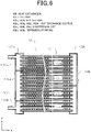
- FIG. 6 is a conventional heat exchanger disclosed in Japanese Patent Laid-Open No. 2014-48028 .
- a heat exchanger 100 is constituted by a plurality of flat pipes 101 formed by a plurality of refrigerant flow paths and a pair of header pipes 102a, 102b each of which connects both ends of the flat pipes 101, and to the header pipes 102a, 102b, partition plates 104a, 104b and 104c are provided to divide the plurality of flat pipes 101 into a plurality of heat exchange sections 103a, 103b, 103c and 103d, and refrigerant piping 105a, 105b are connected to one header pipe 102a.
- the heat exchange sections 103a, 103b are divided by the partition plate 104a, the heat exchange sections 103b, 103c are divided by the partition plate 104b and the heat exchange sections 103c, 103d are divided by the partition plate 104c, respectively.
- the number of flat pipes 101 constituting each of the heat exchange sections 103a, 103b, 103c and 103d are determined as within an upper limit and a lower limit obtained by a formula using a rated capacity for heating, a cross-sectional area of the refrigerant flow path of one flat pipe 101 and a hydraulic diameter.
- refrigerant flows from a refrigerant piping 105b into one header pipe 102a, passes through the heat exchange section 103d, flows to the other header pipe 102b, moves upward in the other header pipe 102b, passes through the heat exchange section 103c and outflows to one header pipe 102a.
- the refrigerant flowing to one header pipe 102a moves upward in one header pipe 102a, passes through the heat exchange section 103b, flows to the other header pipe 102b, moves upward in the other header pipe 102b, passes through the heat exchange section 103a and flows to one header pipe 102a.
- the refrigerant When the heat exchanger 100 is used as the evaporator, the refrigerant is evaporated each time when it flows in each heat exchange section, and along the flowing from an inlet to an outlet of the heat exchanger, the refrigerant is changed from a liquid state (liquid rich) to a gas state (gas rich), so that a state of refrigerant which should be distributed to each heat exchange section differs. Since the state of refrigerant differs, a flowing state of the refrigerant differs. However, in a conventional configuration, shunt current improvement is insufficient since a difference of the state of refrigerant is not considered.
- US 2013/0126140 describes a heat exchanger according to the preamble of claim 1, that includes a plurality of refrigerant tubes extending in a horizontal direction, at least one fin coupled to the plurality of refrigerant tubes, a vertically oriented header coupled to corresponding ends of the plurality of refrigerant tubes, the header distributing refrigerant into the plurality of refrigerant tubes, and a partition device that partitions an inner space of the header, the partition device including at least two through holes that guide refrigerant into the plurality of refrigerant tubes.
- US 2008/0023185 describes a heat exchanger assembly including a first single-piece manifold and a second single-piece manifold spaced from and parallel to the first single-piece manifold.
- Each of the first and second single-piece manifolds has a tubular wall defining a flow path.
- a plurality of flow tubes extend in parallel between the first and second single-piece manifolds and are in fluid communication with the flow paths.
- An insert having a distribution surface is slidably disposed in the flow path of the first single-piece manifold to establish a distribution chamber within the first single-piece manifold.
- a series of orifices defined in the distribution surface of the insert are in fluid communication with the flow path and the distribution chamber for uniformly distributing a heat exchange fluid between the flow path and the flow tubes.
- the present invention resolves the conventional problem, and an object of the present invention is to evenly flow refrigerant into a plurality of flat pipes in a heat exchanger constituted by the plurality of flat pipes formed by a plurality of refrigerant flow paths and a pair of header pipes each of which connects both ends of the flat pipes.
- the refrigerant flowing from the plurality of flat pipes to the header pipe flows into a non-connection-side space of the flat pipe of a refrigerant outflow section to move upward.
- a flow distance of refrigerant from a second refrigerant piping is short and energy lost by pressure loss and a head difference is small. Accordingly, the refrigerant flows while kinetic energy is kept from the state where the refrigerant flows into the heat exchanger, so that inertia of moving upward in the header pipe is large and the refrigerant reaches an upper portion of the non-connection-side space.
- the refrigerant flowing from the plurality of flat pipes into the header pipe moves upward in the header pipe, the refrigerant flows from the lower communication hole to the connection-side space of the flat pipe while preventing uneven flow of the refrigerant to the upper portion of the header pipe due to inertia, so that the refrigerant can be evenly flowed to the plurality of flat pipes.
- a heat exchanger shunt including among others: a plurality of flat pipes having a plurality of refrigerant flow paths; and a pair of header pipes each of which connects both ends of the flat pipes, wherein the header pipes each include a partition plate which divides the plurality of flat pipes into a plurality of heat exchange sections, when the heat exchanger functions as an evaporator, a first refrigerant piping from which refrigerant outflows is provided to an upper portion of one header pipe of the header pipes, while a second refrigerant piping into which the refrigerant flows is provided to a lower portion of the one header pipe, the header pipe of the header pipes includes a partition wall which divides a connection-side space of the flat pipes and a non-connection-side space of the flat pipes in a refrigerant outflow section from which the refrigerant outflows to the plurality of flat pipes, the partition wall includes a plurality of communication holes arranged in a vertical direction, and one communication hole
- the refrigerant flowing from the plurality of flat pipes into the header pipe flows in a non-connection-side space of the flat pipe of a refrigerant outflow section to move upward.
- a flow distance of refrigerant from a second refrigerant piping is short and energy lost by pressure loss and a head difference is small. Accordingly, the refrigerant flows while kinetic energy is kept from the state where the refrigerant flows into the heat exchanger, so that inertia of moving upward in the header pipe is large and the refrigerant reaches an upper portion of the non-connection-side space.
- the refrigerant flowing from the plurality of flat pipes to the header pipe moves upward into the header pipe, the refrigerant flows from the lower communication hole to the connection-side space of the flat pipe while preventing uneven flow of the refrigerant to the upper portion of the header pipe due to inertia, so that the refrigerant can be evenly flowed to the plurality of flat pipes.
- the other header is provided with a damming plate, which has an updraft hole and which is provided between the plurality of communication holes, so that the heat exchange section in the other header pipe is divided into a plurality of heat exchange sections and the updraft hole is located at the non-connection-side space of the flat pipe.
- one part of the refrigerant moving upward in the non-connection-side space of the flat pipe passes through the updraft hole of the damming plate, moves upward and flows in the connection-side space of the flat pipe from an upper communication hole of the plurality of communication holes, while another part of the refrigerant collides with a lower surface of the damming plate to reduce kinetic energy, does not move upward and flows in the connection-side space of the flat pipe from a lower communication hole of the plurality of communication holes.
- an opening area of the updraft hole is smaller than an opening area of the lower communication hole of the plurality of communication holes.
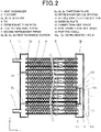
- FIG. 1 is a perspective view of a heat exchanger of a first embodiment of the present invention, in which an x direction is a flowing direction of refrigerant which flows in a flow path of a flat pipe, a y direction is an axial direction of a header pipe and a z direction is a flowing direction of air.
- FIG. 2 is a cross-sectional view taken along the line A-A of FIG. 1 (a cross-sectional view of an x-y plane of the heat exchanger according to the first embodiment of the present invention.)
- a heat exchanger 1 includes a plurality of flat pipes 2 and a pair of header pipes 3a, 3b.
- the plurality of flat pipes 2 is arranged in a horizontal direction (the x direction) to be parallel with each other along the axial direction of the header pipes 3a, 3b (the y direction.)
- a plurality of fins 4 formed as undulant continuing in the up-down direction is provided, and heat exchange is executed between air flowing in the plurality of fins 4 and refrigerant flowing in the plurality of flat pipes 2.
- refrigerant for example, R410A, R32 and mixed refrigerants including R32 are used.
- a plurality of refrigerant flow paths 5 provided in the flat pipes 2 communicates with an inner portion of the header pipes 3a, 3b.
- the header pipes 3a, 3b are cylindrically formed by extrusion molding of a metal material such as aluminum.
- first refrigerant piping 6 and a second refrigerant piping 7 are connected to one header pipe 3a.
- the first refrigerant piping 6 is connected to an upper portion of the one header pipe 3a and the second refrigerant piping 7 is connected to a lower portion of one header pipe 3a so that the first refrigerant piping 6 and the second refrigerant piping 7 are configured to function as a flow inlet or a flow outlet of refrigerant.
- partition plates 9a, 9b and 9c which divide the plurality of flat pipes 2 into a plurality of heat exchange sections 8a, 8b, 8c and 8d are provided.
- the heat exchange sections 8a, 8b are divided by the partition plate 9a
- the heat exchange sections 8b, 8c are divided by the partition plate 9b
- the heat exchange sections 8c, 8d are divided by the partition plate 9c, respectively.
- the dividing plate 12 is installed at a position with the same height in the y direction as the partition plate 9c provided in one header pipe 3a.
- the partition wall 15 includes a plurality of communication holes 16a, 16b arranged in a vertical direction (the y direction), and the communication hole 16a is configured to have a smaller opening area than an opening area of the communication hole 16b immediately below the communication hole 16a.
- refrigerant flowing from the second refrigerant piping 7 into one header pipe 3a passes through the heat exchange section 8d in +x direction, and flows to the refrigerant inflow section 10 of the other header pipe 3b.
- the refrigerant in the refrigerant inflow section 10 moves toward the refrigerant outflow section 11, and moves upward in the non-connection-side space 14 in +y direction.
- the raised refrigerant passes through a plurality of communication holes 16a, 16b provided to the partition wall 15, flows in the connection-side space 13, passes through the heat exchange section 8c in -x direction and outflows to one header pipe 3a.
- the refrigerant flowing to one header pipe 3a passes through the heat exchange section 8b in the +x direction, and flows to the other header pipe 3b, moves upward in the other header pipe 3b in the +y direction, passes through the heat exchange section 8a in the -x direction and flows to one header pipe 3a.
- FIG. 3 is a plan view of an x-z plane showing an internal structure of the outdoor unit 20 applying the heat exchanger 1 of the present embodiment.
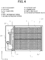
- FIG. 4 is a plan view of the x-y plane showing the internal structure of the outdoor unit 20 applying the heat exchanger 1 of the present embodiment.
- the outdoor unit 20 includes a compressor 21, a switching valve 22, an outdoor expansion valve 23, a blower 24 and the heat exchanger 1.
- the outdoor unit 20 and an indoor unit are connected by a liquid pipe 25 and a gas pipe 26.
- the header pipes 3a, 3b of the heat exchanger 1 are connected to the switching valve 22 via the first refrigerant piping 6 and connected to the outdoor expansion valve 23 via the second refrigerant piping 7, respectively.
- the heat exchanger 1 functions as a condenser.
- Gas refrigerant sent from the compressor 21 of the outdoor unit 20 is allowed to flow from the first refrigerant piping 6 into one header pipe 3a via the switching valve 22.
- the gas refrigerant passes through an inner portion of one header pipe 3a on a connecting side of the first refrigerant piping 6 divided by the partition plate 9a, is allowed to flow into the plurality of refrigerant flow paths 5 in the plurality of flat pipes 2, flows in the heat exchange section 8a in a horizontal direction (the +x direction and +z direction) and outflows to the other header pipe 3b.
- the outflowed refrigerant moves downward in the other header pipe 3b in the vertical direction (-y direction), flows into the heat exchange section 8b, flows in the horizontal direction (-z direction and the -x direction) and outflows to one header pipe 3a.
- the refrigerant outflowed to one header pipe 3a moves downward in one header pipe 3a in the vertical direction (-y direction), flows into the heat exchange section 8c, flows in the horizontal direction (the +z direction, the +x direction) and outflows to the other header pipe 3b.
- the outflowed refrigerant passes through the plurality of communication holes 16a, 16b provided to the partition wall 15 from the connection-side space 13, flows in the non-connection-side space 14, moves downward in the other header pipe 3b in the vertical direction (the -y direction), flows into the heat exchange section 8d, and flows in the horizontal direction (the -z direction, the -x direction.)
- the refrigerant dissipates heat to be condensed in the flat pipe 2 by executing heat exchange with air sent from the blower 24.
- the condensed refrigerant flowed into the indoor unit absorbs heat to be evaporated by executing heat exchange with air in an indoor heat exchanger (not shown.)
- the evaporated refrigerant passes through the gas pipe 26, and via the switching valve 22, circulates to the compressor 21.
- the heat exchanger 1 When heating operation is executed, the heat exchanger 1 functions as the evaporator.
- Gas refrigerant sent from the compressor 21 of the outdoor unit 20 passes through the gas pipe 26 via the switching valve 22 and is outflowed to the indoor unit.
- the gas refrigerant sent to the indoor unit dissipates heat to be condensed by executing heat exchange with air in the indoor heat exchanger provided in the indoor unit.
- connection-side space 13 One part of the refrigerant moving upward flows in the connection-side space 13 from the lower communication hole 16b provided at the partition wall 15 with a large opening area and a small flow path resistance while moving upward in the vertical direction (the +y direction), while another part of the refrigerant reaches an upper portion of the non-connection-side space 14 and flows in the connection-side space 13 from the upper communication hole 16a provided at the partition wall 15.
- connection-side space 13 flows into the heat exchange section 8c, flows in the horizontal direction (the -z direction, the -x direction) and outflows to one header pipe 3a.
- the refrigerant outflowed to one header pipe 3a moves upward in one header pipe 3a in the vertical direction (the +y direction), flows into the heat exchange section 8b, flows in the horizontal direction (the +x direction, the +z direction) and flows to the other header pipe 3b.
- the outflowed refrigerant moves upward in the other header pipe 3b in the vertical direction (the +y direction), flows into the heat exchange section 8a and flows in the horizontal direction (the -z direction, the -x direction.)
- the header pipes 3a, 3b include the partition plates 9a, 9c and 9c which divide the plurality of flat pipes 2 into the plurality of heat exchange sections 8a, 8b, 8c and 8d, and when the heat exchanger 1 functions as an evaporator, the first refrigerant piping 6 from which the refrigerant outflows is provided at the upper portion of one header pipe 3a, while the second refrigerant piping 7 into which the refrigerant flows is provided at the lower portion of the one header pipe 3a.
- the partition wall 15 which divides the connection-side space 13 of the flat pipe 2 and the non-connection-side space 14 of the flat pipe 2 is included, the partition wall 15 includes the plurality of communication holes 16a, 16b arranged in the vertical direction (the y direction), and the communication hole 16a is configured to have a smaller opening area than the opening area of the communication hole 16b immediately below the communication hole 16a.
- the refrigerant flowing from the plurality of flat pipes 2 into the other header pipe 3b flows in the non-connection-side space 14 of the flat pipe 2 of the refrigerant outflow section 11 to move upward.
- a flow distance of refrigerant from the second refrigerant piping 7 is short and energy lost by pressure loss and a head difference is small.
- the refrigerant flows while kinetic energy is kept from the state where the refrigerant flows into the heat exchanger 1, so that inertia of moving upward in the other header pipe 3b is large and the refrigerant reaches an upper portion of the non-connection-side space 14.
- the refrigerant flowing from the plurality of flat pipes 2 into the other header pipe 3b moves upward in the other header pipe 3b, the refrigerant flows from the lower communication hole 16b to the connection-side space 13 of the flat pipe 2 while preventing uneven flow of the refrigerant to an upper portion of the other header pipe 3b due to a centrifugal force, so that the refrigerant can be evenly flowed to the plurality of flat pipes 2.
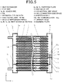
- FIG. 5 is a cross-sectional view of the x-y plane of a second embodiment of the present invention.
- a damming plate 18 having an updraft hole 17 is provided between the plurality of communication holes 16a, 16b, so that the heat exchange section 8c is divided into a plurality of heat exchange sections and the updraft hole 17 is located at the non-connection-side space 14 of the flat pipe 2.
- one part of the refrigerant moving upward in the non-connection-side space 14 of the flat pipe 2 passes through the updraft hole 17 of the damming plate 18, moves upward and flows in the connection-side space 13 of the flat pipe 2 from an upper communication hole 16a of the plurality of communication holes 16a, 16b, while another part of the refrigerant collides with a lower surface of the damming plate 18 to reduce kinetic energy, does not move upward and flows in the connection-side space 13 of the flat pipe 2 from a lower communication hole 16b of the plurality of communication holes 16a, 16b.
- an opening area of the updraft hole 17 of the damming plate 18 is preferably less than an opening area of the lower communication hole 16b of the plurality of communication holes 16a, 16b.
- the plurality of communication holes 16a, 16b is preferably provided such that the number of flat pipes 2 connected to the refrigerant outflow section 11 is evenly divided by the number of communication holes 16a, 16b with inclusion of at least a height position in the y direction of the flat pipe 2 existing at the uppermost stage of the plurality of divided flat pipes 2.
- the upper communication hole 16a includes a height position in the y direction of the flat pipe 2 at the uppermost stage of the eight flat pipes 2
- the lower communication hole 16b includes a height position in the y direction of the fifth flat pipe 2 from the top of the eight flat pipes 2.
- one array of the heat exchanger 1 is installed in the example, for example two or more of the heat exchangers may be provided in an air flowing direction (the z direction), and needless to say, the similar effect can be obtained even when the configuration in which two or more heat exchangers 1 are arranged in a direction of gravitational force (the y direction) is used.
- the similar effect can be obtained even when the configuration that the fins are formed plate-like such that they are orthogonally inserted into the plurality of flat pipes 2 to be parallel with each other.
- the present invention relates to a heat exchanger shunt which inhibits, when refrigerant with a large ratio of the liquid refrigerant with a high density (liquid rich) flows into a header pipe in a heat exchanger using flat pipes, uneven flow of liquid refrigerant to an upper portion due to momentum of moving upward in the header pipe since the refrigerant flows in the header pipe from the flat pipe.
- this heat exchanger shunt can be applied to usage for a refrigerator, an air conditioner and a composite device for hot-water supply and air conditioning etc.
Landscapes
- Engineering & Computer Science (AREA)
- Physics & Mathematics (AREA)
- Thermal Sciences (AREA)
- Mechanical Engineering (AREA)
- General Engineering & Computer Science (AREA)
- Details Of Heat-Exchange And Heat-Transfer (AREA)
- Heat-Exchange Devices With Radiators And Conduit Assemblies (AREA)
Claims (3)
- Dérivation d'échangeur de chaleur comprenant :une pluralité de tuyaux plats (2) présentant une pluralité de trajets d'écoulement de fluide frigorigène (5) ; etune paire de tuyaux collecteurs (3a, 3b) dont chacun relie les deux extrémités des tuyaux plats,les tuyaux collecteurs comprenant chacun une plaque de séparation (9a, 9b, 9c) qui sépare la pluralité de tuyaux plats en une pluralité de sections d'échange de chaleur (8a, 8b, 8c, 8d),une première tuyauterie de fluide frigorigène (6) étant disposée sur une partie supérieure d'un tuyau collecteur parmi les tuyaux collecteurs, tandis qu'une deuxième tuyauterie de fluide frigorigène (7) est disposée sur une partie inférieure dudit un tuyau collecteur de telle sorte que le fluide frigorigène s'écoule à partir de la première tuyauterie de fluide frigorigène (6) dans la deuxième tuyauterie de fluide frigorigène (7) lorsque l'échangeur de chaleur fonctionne comme un évaporateur,l'autre tuyau collecteur parmi les tuyaux collecteurs comprenant une paroi de séparation (15) qui sépare un espace côté raccordement (13) des tuyaux plats et un espace côté non-raccordement (14) des tuyaux plats dans une section de sortie de fluide frigorigène (11) à partir de laquelle le fluide frigorigène s'écoule vers la pluralité de tuyaux plats,la paroi de séparation comprenant une pluralité de trous de communication (16a, 16b) agencés dans une direction verticale etun trou de communication parmi les trous de communication présentant une zone d'ouverture plus petite qu'une zone d'ouverture d'un autre trou de communication parmi les trous de communication, qui est en utilisation immédiatement au-dessous dudit un trou de communicationcaractérisée en ce quel'autre tuyau collecteur est pourvu d'une plaque de retenue (18), qui présente un trou à courant ascendant (17) et qui est disposée entre la pluralité de trous de communication, de telle sorte que la section d'échange de chaleur dans l'autre tuyau collecteur est séparée en une pluralité de sections d'échange de chaleur et le trou à courant ascendant est situé au niveau de l'espace côté non-raccordement.
- Dérivation d'échangeur de chaleur selon la revendication 1, une zone d'ouverture du trou à courant ascendant étant plus petite qu'une zone d'ouverture d'un trou de communication inférieur de la pluralité de trous de communication pendant l'utilisation.
- Unité extérieure comprenant la dérivation d'échangeur de chaleur selon la revendication 1 ou 2.
Applications Claiming Priority (1)
| Application Number | Priority Date | Filing Date | Title |
|---|---|---|---|
| JP2019065599A JP2020165578A (ja) | 2019-03-29 | 2019-03-29 | 熱交換器分流器 |
Publications (2)
| Publication Number | Publication Date |
|---|---|
| EP3715760A1 EP3715760A1 (fr) | 2020-09-30 |
| EP3715760B1 true EP3715760B1 (fr) | 2022-08-10 |
Family
ID=69374149
Family Applications (1)
| Application Number | Title | Priority Date | Filing Date |
|---|---|---|---|
| EP20153957.4A Active EP3715760B1 (fr) | 2019-03-29 | 2020-01-27 | Dérivation d'échangeur de chaleur |
Country Status (3)
| Country | Link |
|---|---|
| EP (1) | EP3715760B1 (fr) |
| JP (1) | JP2020165578A (fr) |
| CN (1) | CN111750573B (fr) |
Families Citing this family (1)
| Publication number | Priority date | Publication date | Assignee | Title |
|---|---|---|---|---|
| JP6970363B1 (ja) | 2020-09-30 | 2021-11-24 | ダイキン工業株式会社 | 圧縮装置 |
Family Cites Families (12)
| Publication number | Priority date | Publication date | Assignee | Title |
|---|---|---|---|---|
| JPH05346297A (ja) * | 1992-06-15 | 1993-12-27 | Nippon Light Metal Co Ltd | 熱交換器 |
| JP2007192502A (ja) * | 2006-01-20 | 2007-08-02 | Denso Corp | 熱交換器 |
| US20080023185A1 (en) * | 2006-07-25 | 2008-01-31 | Henry Earl Beamer | Heat exchanger assembly |
| BRPI0811928A2 (pt) * | 2007-05-22 | 2014-11-25 | Behr Gmbh & Co Kg | Trocador de calor |
| KR101372096B1 (ko) * | 2011-11-18 | 2014-03-07 | 엘지전자 주식회사 | 열교환기 |
| US9551540B2 (en) * | 2011-11-22 | 2017-01-24 | Daikin Industries, Ltd. | Heat exchanger |
| KR101826365B1 (ko) * | 2012-05-04 | 2018-03-22 | 엘지전자 주식회사 | 열교환기 |
| JP5858478B2 (ja) | 2012-09-04 | 2016-02-10 | シャープ株式会社 | パラレルフロー型熱交換器及びそれを搭載した空気調和機 |
| JP2015055408A (ja) * | 2013-09-11 | 2015-03-23 | ダイキン工業株式会社 | 熱交換器及び空気調和機 |
| JP6070685B2 (ja) * | 2014-12-26 | 2017-02-01 | ダイキン工業株式会社 | 熱交換器および空気調和装置 |
| CN204944263U (zh) * | 2015-07-23 | 2016-01-06 | 中国石油化工股份有限公司 | 一种流体分配管道以及冷却装置 |
| JP2018091503A (ja) * | 2016-11-30 | 2018-06-14 | ダイキン工業株式会社 | 熱交換器 |
-
2019
- 2019-03-29 JP JP2019065599A patent/JP2020165578A/ja active Pending
-
2020
- 2020-01-22 CN CN202010074308.6A patent/CN111750573B/zh not_active Expired - Fee Related
- 2020-01-27 EP EP20153957.4A patent/EP3715760B1/fr active Active
Also Published As
| Publication number | Publication date |
|---|---|
| CN111750573B (zh) | 2023-04-07 |
| CN111750573A (zh) | 2020-10-09 |
| JP2020165578A (ja) | 2020-10-08 |
| EP3715760A1 (fr) | 2020-09-30 |
Similar Documents
| Publication | Publication Date | Title |
|---|---|---|
| AU2014391505B2 (en) | Air conditioner | |
| KR101462176B1 (ko) | 열교환기 | |
| CN108139089B (zh) | 空气调节机的室外机及室内机 | |
| KR20160131577A (ko) | 공기조화기의 열교환기 | |
| US20160223231A1 (en) | Heat exchanger and air conditioner | |
| EP3141859B1 (fr) | Échangeur de chaleur de type à microcanaux | |
| CN115298507B (zh) | 换热器 | |
| WO2018062519A1 (fr) | Échangeur de chaleur et climatiseur | |
| KR20170067351A (ko) | 열교환기 | |
| WO2015046275A1 (fr) | Échangeur thermique et appareil de climatisation utilisant cet échangeur thermique | |
| KR101837046B1 (ko) | 열교환기 | |
| JP2018194251A (ja) | 熱交換器 | |
| EP3715760B1 (fr) | Dérivation d'échangeur de chaleur | |
| CN110832260A (zh) | 热交换器及制冷循环装置 | |
| JP2020085267A (ja) | 熱交換器 | |
| EP3139122B1 (fr) | Échangeur de chaleur de type a micro-canal | |
| EP3715761B1 (fr) | Dérivation d'échangeur de chaleur | |
| JP7313557B2 (ja) | 冷媒分配器、熱交換器および空気調和装置 | |
| KR101822898B1 (ko) | 하이브리드모듈 및 이를 이용한 공기조화기 | |
| WO2022264348A1 (fr) | Échangeur de chaleur et dispositif à cycle de réfrigération | |
| JP2020112274A (ja) | 熱交換器 | |
| JP2020115070A (ja) | 熱交換器 | |
| JP2020085268A (ja) | 熱交換器 | |
| JP7726323B1 (ja) | 熱交換器および空気調和機の室外機 | |
| JP6977184B1 (ja) | 空気調和機、冷凍機及び分配器 |
Legal Events
| Date | Code | Title | Description |
|---|---|---|---|
| PUAI | Public reference made under article 153(3) epc to a published international application that has entered the european phase |
Free format text: ORIGINAL CODE: 0009012 |
|
| STAA | Information on the status of an ep patent application or granted ep patent |
Free format text: STATUS: THE APPLICATION HAS BEEN PUBLISHED |
|
| AK | Designated contracting states |
Kind code of ref document: A1 Designated state(s): AL AT BE BG CH CY CZ DE DK EE ES FI FR GB GR HR HU IE IS IT LI LT LU LV MC MK MT NL NO PL PT RO RS SE SI SK SM TR |
|
| AX | Request for extension of the european patent |
Extension state: BA ME |
|
| STAA | Information on the status of an ep patent application or granted ep patent |
Free format text: STATUS: REQUEST FOR EXAMINATION WAS MADE |
|
| 17P | Request for examination filed |
Effective date: 20210210 |
|
| RBV | Designated contracting states (corrected) |
Designated state(s): AL AT BE BG CH CY CZ DE DK EE ES FI FR GB GR HR HU IE IS IT LI LT LU LV MC MK MT NL NO PL PT RO RS SE SI SK SM TR |
|
| GRAP | Despatch of communication of intention to grant a patent |
Free format text: ORIGINAL CODE: EPIDOSNIGR1 |
|
| STAA | Information on the status of an ep patent application or granted ep patent |
Free format text: STATUS: GRANT OF PATENT IS INTENDED |
|
| INTG | Intention to grant announced |
Effective date: 20220301 |
|
| GRAS | Grant fee paid |
Free format text: ORIGINAL CODE: EPIDOSNIGR3 |
|
| GRAA | (expected) grant |
Free format text: ORIGINAL CODE: 0009210 |
|
| STAA | Information on the status of an ep patent application or granted ep patent |
Free format text: STATUS: THE PATENT HAS BEEN GRANTED |
|
| AK | Designated contracting states |
Kind code of ref document: B1 Designated state(s): AL AT BE BG CH CY CZ DE DK EE ES FI FR GB GR HR HU IE IS IT LI LT LU LV MC MK MT NL NO PL PT RO RS SE SI SK SM TR |
|
| REG | Reference to a national code |
Ref country code: AT Ref legal event code: REF Ref document number: 1510841 Country of ref document: AT Kind code of ref document: T Effective date: 20220815 Ref country code: CH Ref legal event code: EP |
|
| REG | Reference to a national code |
Ref country code: DE Ref legal event code: R096 Ref document number: 602020004380 Country of ref document: DE |
|
| REG | Reference to a national code |
Ref country code: IE Ref legal event code: FG4D |
|
| REG | Reference to a national code |
Ref country code: NL Ref legal event code: MP Effective date: 20220810 |
|
| REG | Reference to a national code |
Ref country code: LT Ref legal event code: MG9D |
|
| PG25 | Lapsed in a contracting state [announced via postgrant information from national office to epo] |
Ref country code: SE Free format text: LAPSE BECAUSE OF FAILURE TO SUBMIT A TRANSLATION OF THE DESCRIPTION OR TO PAY THE FEE WITHIN THE PRESCRIBED TIME-LIMIT Effective date: 20220810 Ref country code: RS Free format text: LAPSE BECAUSE OF FAILURE TO SUBMIT A TRANSLATION OF THE DESCRIPTION OR TO PAY THE FEE WITHIN THE PRESCRIBED TIME-LIMIT Effective date: 20220810 Ref country code: PT Free format text: LAPSE BECAUSE OF FAILURE TO SUBMIT A TRANSLATION OF THE DESCRIPTION OR TO PAY THE FEE WITHIN THE PRESCRIBED TIME-LIMIT Effective date: 20221212 Ref country code: NO Free format text: LAPSE BECAUSE OF FAILURE TO SUBMIT A TRANSLATION OF THE DESCRIPTION OR TO PAY THE FEE WITHIN THE PRESCRIBED TIME-LIMIT Effective date: 20221110 Ref country code: NL Free format text: LAPSE BECAUSE OF FAILURE TO SUBMIT A TRANSLATION OF THE DESCRIPTION OR TO PAY THE FEE WITHIN THE PRESCRIBED TIME-LIMIT Effective date: 20220810 Ref country code: LV Free format text: LAPSE BECAUSE OF FAILURE TO SUBMIT A TRANSLATION OF THE DESCRIPTION OR TO PAY THE FEE WITHIN THE PRESCRIBED TIME-LIMIT Effective date: 20220810 Ref country code: LT Free format text: LAPSE BECAUSE OF FAILURE TO SUBMIT A TRANSLATION OF THE DESCRIPTION OR TO PAY THE FEE WITHIN THE PRESCRIBED TIME-LIMIT Effective date: 20220810 Ref country code: FI Free format text: LAPSE BECAUSE OF FAILURE TO SUBMIT A TRANSLATION OF THE DESCRIPTION OR TO PAY THE FEE WITHIN THE PRESCRIBED TIME-LIMIT Effective date: 20220810 |
|
| REG | Reference to a national code |
Ref country code: AT Ref legal event code: MK05 Ref document number: 1510841 Country of ref document: AT Kind code of ref document: T Effective date: 20220810 |
|
| PG25 | Lapsed in a contracting state [announced via postgrant information from national office to epo] |
Ref country code: PL Free format text: LAPSE BECAUSE OF FAILURE TO SUBMIT A TRANSLATION OF THE DESCRIPTION OR TO PAY THE FEE WITHIN THE PRESCRIBED TIME-LIMIT Effective date: 20220810 Ref country code: IS Free format text: LAPSE BECAUSE OF FAILURE TO SUBMIT A TRANSLATION OF THE DESCRIPTION OR TO PAY THE FEE WITHIN THE PRESCRIBED TIME-LIMIT Effective date: 20221210 Ref country code: HR Free format text: LAPSE BECAUSE OF FAILURE TO SUBMIT A TRANSLATION OF THE DESCRIPTION OR TO PAY THE FEE WITHIN THE PRESCRIBED TIME-LIMIT Effective date: 20220810 Ref country code: GR Free format text: LAPSE BECAUSE OF FAILURE TO SUBMIT A TRANSLATION OF THE DESCRIPTION OR TO PAY THE FEE WITHIN THE PRESCRIBED TIME-LIMIT Effective date: 20221111 |
|
| PG25 | Lapsed in a contracting state [announced via postgrant information from national office to epo] |
Ref country code: SM Free format text: LAPSE BECAUSE OF FAILURE TO SUBMIT A TRANSLATION OF THE DESCRIPTION OR TO PAY THE FEE WITHIN THE PRESCRIBED TIME-LIMIT Effective date: 20220810 Ref country code: RO Free format text: LAPSE BECAUSE OF FAILURE TO SUBMIT A TRANSLATION OF THE DESCRIPTION OR TO PAY THE FEE WITHIN THE PRESCRIBED TIME-LIMIT Effective date: 20220810 Ref country code: ES Free format text: LAPSE BECAUSE OF FAILURE TO SUBMIT A TRANSLATION OF THE DESCRIPTION OR TO PAY THE FEE WITHIN THE PRESCRIBED TIME-LIMIT Effective date: 20220810 Ref country code: DK Free format text: LAPSE BECAUSE OF FAILURE TO SUBMIT A TRANSLATION OF THE DESCRIPTION OR TO PAY THE FEE WITHIN THE PRESCRIBED TIME-LIMIT Effective date: 20220810 Ref country code: CZ Free format text: LAPSE BECAUSE OF FAILURE TO SUBMIT A TRANSLATION OF THE DESCRIPTION OR TO PAY THE FEE WITHIN THE PRESCRIBED TIME-LIMIT Effective date: 20220810 Ref country code: AT Free format text: LAPSE BECAUSE OF FAILURE TO SUBMIT A TRANSLATION OF THE DESCRIPTION OR TO PAY THE FEE WITHIN THE PRESCRIBED TIME-LIMIT Effective date: 20220810 |
|
| REG | Reference to a national code |
Ref country code: DE Ref legal event code: R097 Ref document number: 602020004380 Country of ref document: DE |
|
| PG25 | Lapsed in a contracting state [announced via postgrant information from national office to epo] |
Ref country code: SK Free format text: LAPSE BECAUSE OF FAILURE TO SUBMIT A TRANSLATION OF THE DESCRIPTION OR TO PAY THE FEE WITHIN THE PRESCRIBED TIME-LIMIT Effective date: 20220810 Ref country code: EE Free format text: LAPSE BECAUSE OF FAILURE TO SUBMIT A TRANSLATION OF THE DESCRIPTION OR TO PAY THE FEE WITHIN THE PRESCRIBED TIME-LIMIT Effective date: 20220810 |
|
| PLBE | No opposition filed within time limit |
Free format text: ORIGINAL CODE: 0009261 |
|
| STAA | Information on the status of an ep patent application or granted ep patent |
Free format text: STATUS: NO OPPOSITION FILED WITHIN TIME LIMIT |
|
| PG25 | Lapsed in a contracting state [announced via postgrant information from national office to epo] |
Ref country code: AL Free format text: LAPSE BECAUSE OF FAILURE TO SUBMIT A TRANSLATION OF THE DESCRIPTION OR TO PAY THE FEE WITHIN THE PRESCRIBED TIME-LIMIT Effective date: 20220810 |
|
| 26N | No opposition filed |
Effective date: 20230511 |
|
| PG25 | Lapsed in a contracting state [announced via postgrant information from national office to epo] |
Ref country code: SI Free format text: LAPSE BECAUSE OF FAILURE TO SUBMIT A TRANSLATION OF THE DESCRIPTION OR TO PAY THE FEE WITHIN THE PRESCRIBED TIME-LIMIT Effective date: 20220810 |
|
| REG | Reference to a national code |
Ref country code: CH Ref legal event code: PL |
|
| PG25 | Lapsed in a contracting state [announced via postgrant information from national office to epo] |
Ref country code: LU Free format text: LAPSE BECAUSE OF NON-PAYMENT OF DUE FEES Effective date: 20230127 |
|
| REG | Reference to a national code |
Ref country code: BE Ref legal event code: MM Effective date: 20230131 |
|
| PG25 | Lapsed in a contracting state [announced via postgrant information from national office to epo] |
Ref country code: LI Free format text: LAPSE BECAUSE OF NON-PAYMENT OF DUE FEES Effective date: 20230131 Ref country code: CH Free format text: LAPSE BECAUSE OF NON-PAYMENT OF DUE FEES Effective date: 20230131 |
|
| PG25 | Lapsed in a contracting state [announced via postgrant information from national office to epo] |
Ref country code: BE Free format text: LAPSE BECAUSE OF NON-PAYMENT OF DUE FEES Effective date: 20230131 |
|
| PG25 | Lapsed in a contracting state [announced via postgrant information from national office to epo] |
Ref country code: IE Free format text: LAPSE BECAUSE OF NON-PAYMENT OF DUE FEES Effective date: 20230127 |
|
| PG25 | Lapsed in a contracting state [announced via postgrant information from national office to epo] |
Ref country code: IT Free format text: LAPSE BECAUSE OF FAILURE TO SUBMIT A TRANSLATION OF THE DESCRIPTION OR TO PAY THE FEE WITHIN THE PRESCRIBED TIME-LIMIT Effective date: 20220810 |
|
| PG25 | Lapsed in a contracting state [announced via postgrant information from national office to epo] |
Ref country code: MC Free format text: LAPSE BECAUSE OF FAILURE TO SUBMIT A TRANSLATION OF THE DESCRIPTION OR TO PAY THE FEE WITHIN THE PRESCRIBED TIME-LIMIT Effective date: 20220810 |
|
| PG25 | Lapsed in a contracting state [announced via postgrant information from national office to epo] |
Ref country code: MC Free format text: LAPSE BECAUSE OF FAILURE TO SUBMIT A TRANSLATION OF THE DESCRIPTION OR TO PAY THE FEE WITHIN THE PRESCRIBED TIME-LIMIT Effective date: 20220810 |
|
| PG25 | Lapsed in a contracting state [announced via postgrant information from national office to epo] |
Ref country code: BG Free format text: LAPSE BECAUSE OF FAILURE TO SUBMIT A TRANSLATION OF THE DESCRIPTION OR TO PAY THE FEE WITHIN THE PRESCRIBED TIME-LIMIT Effective date: 20220810 |
|
| PG25 | Lapsed in a contracting state [announced via postgrant information from national office to epo] |
Ref country code: BG Free format text: LAPSE BECAUSE OF FAILURE TO SUBMIT A TRANSLATION OF THE DESCRIPTION OR TO PAY THE FEE WITHIN THE PRESCRIBED TIME-LIMIT Effective date: 20220810 |
|
| PGFP | Annual fee paid to national office [announced via postgrant information from national office to epo] |
Ref country code: DE Payment date: 20250121 Year of fee payment: 6 |
|
| PGFP | Annual fee paid to national office [announced via postgrant information from national office to epo] |
Ref country code: FR Payment date: 20250127 Year of fee payment: 6 |
|
| PGFP | Annual fee paid to national office [announced via postgrant information from national office to epo] |
Ref country code: GB Payment date: 20250128 Year of fee payment: 6 |
|
| PG25 | Lapsed in a contracting state [announced via postgrant information from national office to epo] |
Ref country code: CY Free format text: LAPSE BECAUSE OF FAILURE TO SUBMIT A TRANSLATION OF THE DESCRIPTION OR TO PAY THE FEE WITHIN THE PRESCRIBED TIME-LIMIT; INVALID AB INITIO Effective date: 20200127 |
|
| PG25 | Lapsed in a contracting state [announced via postgrant information from national office to epo] |
Ref country code: HU Free format text: LAPSE BECAUSE OF FAILURE TO SUBMIT A TRANSLATION OF THE DESCRIPTION OR TO PAY THE FEE WITHIN THE PRESCRIBED TIME-LIMIT; INVALID AB INITIO Effective date: 20200127 |
|
| PG25 | Lapsed in a contracting state [announced via postgrant information from national office to epo] |
Ref country code: TR Free format text: LAPSE BECAUSE OF FAILURE TO SUBMIT A TRANSLATION OF THE DESCRIPTION OR TO PAY THE FEE WITHIN THE PRESCRIBED TIME-LIMIT Effective date: 20220810 |