EP3715821B1 - Surveillance de pronostic et détection de défaillances de composants rotatifs - Google Patents
Surveillance de pronostic et détection de défaillances de composants rotatifs Download PDFInfo
- Publication number
- EP3715821B1 EP3715821B1 EP19211122.7A EP19211122A EP3715821B1 EP 3715821 B1 EP3715821 B1 EP 3715821B1 EP 19211122 A EP19211122 A EP 19211122A EP 3715821 B1 EP3715821 B1 EP 3715821B1
- Authority
- EP
- European Patent Office
- Prior art keywords
- signal
- electrical signal
- gathering
- rotating component
- sensor
- Prior art date
- Legal status (The legal status is an assumption and is not a legal conclusion. Google has not performed a legal analysis and makes no representation as to the accuracy of the status listed.)
- Active
Links
Images



Classifications
-
- G—PHYSICS
- G01—MEASURING; TESTING
- G01M—TESTING STATIC OR DYNAMIC BALANCE OF MACHINES OR STRUCTURES; TESTING OF STRUCTURES OR APPARATUS, NOT OTHERWISE PROVIDED FOR
- G01M13/00—Testing of machine parts
- G01M13/02—Gearings; Transmission mechanisms
-
- B—PERFORMING OPERATIONS; TRANSPORTING
- B23—MACHINE TOOLS; METAL-WORKING NOT OTHERWISE PROVIDED FOR
- B23P—METAL-WORKING NOT OTHERWISE PROVIDED FOR; COMBINED OPERATIONS; UNIVERSAL MACHINE TOOLS
- B23P6/00—Restoring or reconditioning objects
- B23P6/002—Repairing turbine components, e.g. moving or stationary blades, rotors
-
- G—PHYSICS
- G01—MEASURING; TESTING
- G01D—MEASURING NOT SPECIALLY ADAPTED FOR A SPECIFIC VARIABLE; ARRANGEMENTS FOR MEASURING TWO OR MORE VARIABLES NOT COVERED IN A SINGLE OTHER SUBCLASS; TARIFF METERING APPARATUS; MEASURING OR TESTING NOT OTHERWISE PROVIDED FOR
- G01D5/00—Mechanical means for transferring the output of a sensing member; Means for converting the output of a sensing member to another variable where the form or nature of the sensing member does not constrain the means for converting; Transducers not specially adapted for a specific variable
- G01D5/12—Mechanical means for transferring the output of a sensing member; Means for converting the output of a sensing member to another variable where the form or nature of the sensing member does not constrain the means for converting; Transducers not specially adapted for a specific variable using electric or magnetic means
- G01D5/244—Mechanical means for transferring the output of a sensing member; Means for converting the output of a sensing member to another variable where the form or nature of the sensing member does not constrain the means for converting; Transducers not specially adapted for a specific variable using electric or magnetic means influencing characteristics of pulses or pulse trains; generating pulses or pulse trains
- G01D5/248—Mechanical means for transferring the output of a sensing member; Means for converting the output of a sensing member to another variable where the form or nature of the sensing member does not constrain the means for converting; Transducers not specially adapted for a specific variable using electric or magnetic means influencing characteristics of pulses or pulse trains; generating pulses or pulse trains by varying pulse repetition frequency
-
- F—MECHANICAL ENGINEERING; LIGHTING; HEATING; WEAPONS; BLASTING
- F02—COMBUSTION ENGINES; HOT-GAS OR COMBUSTION-PRODUCT ENGINE PLANTS
- F02C—GAS-TURBINE PLANTS; AIR INTAKES FOR JET-PROPULSION PLANTS; CONTROLLING FUEL SUPPLY IN AIR-BREATHING JET-PROPULSION PLANTS
- F02C7/00—Features, components parts, details or accessories, not provided for in, or of interest apart form groups F02C1/00 - F02C6/00; Air intakes for jet-propulsion plants
- F02C7/26—Starting; Ignition
- F02C7/268—Starting drives for the rotor, acting directly on the rotor of the gas turbine to be started
- F02C7/275—Mechanical drives
- F02C7/277—Mechanical drives the starter being a separate turbine
-
- F—MECHANICAL ENGINEERING; LIGHTING; HEATING; WEAPONS; BLASTING
- F05—INDEXING SCHEMES RELATING TO ENGINES OR PUMPS IN VARIOUS SUBCLASSES OF CLASSES F01-F04
- F05D—INDEXING SCHEME FOR ASPECTS RELATING TO NON-POSITIVE-DISPLACEMENT MACHINES OR ENGINES, GAS-TURBINES OR JET-PROPULSION PLANTS
- F05D2260/00—Function
- F05D2260/80—Diagnostics
Definitions
- This disclosure relates to prognostic monitoring and failure detection of rotating components such as air turbine starter components using magnetic speed sensors.
- a gas turbine engine typically includes a fan section, a compressor section, a combustor section, and a turbine section. Air moves into the engine through the fan section. Airfoil arrays in the compressor section rotate to compress the air, which is then mixed with fuel and combusted in the combustor section. The products of combustion are expanded to rotatably drive airfoil arrays in the turbine section. Rotating the airfoil arrays in the turbine section drives rotation of the fan and compressor sections.
- the compressor section and turbine section each have multiple stages of blades that rotate about a central axis and multiple stages of vanes that are stationary relative to the central axis.
- An air turbine starter is an example of such machinery.
- An ATS is used to initiate gas turbine engine rotation.
- the ATS is typically mounted on the accessory gearbox which, in turn, is mounted on the engine or airframe. Active operation of the ATS may occur for a minute or so at the beginning of each flight cycle, along with occasional operation during engine maintenance activities.
- An ATS encounters large mechanical stresses while converting inlet air pressure into output torque for initiating engine rotation. Each start process causes wear on internal components, such as bearings, shafts, and gears.
- EP 2 684 020 relates to a shaft break detection system.
- EP 1 227 325 relates to a vibration detector.
- US 2005/284225 relates to a gearbox condition monitoring system.
- a method of monitoring a rotating component includes gathering an electrical signal from a sensor arranged adjacent a rotating component of an assembly.
- the electrical signal is transformed from a time domain into a frequency domain.
- the electrical signal is compared to an expected signal.
- the method includes determining whether there is a fault in the assembly based on the comparison to the expected signal.
- the method includes determining a portion of the assembly containing the fault based on the comparison to the expected signal.
- the method includes determining whether the fault corresponds to an issue with a gear system, shaft, or bearing.
- a component of the assembly is replaced or repaired when a fault is detected.
- the comparing step comprises comparing an amplitude of the electrical signal across several frequencies with the expected signal.
- Any high amplitude pulses are removed from the electrical signal before the transforming step.
- the rotating component is a gear that has at least one tooth.
- the high amplitude pulses corresponds to at least one tooth passing the sensor.
- the gear has a plurality of teeth spaced about a circumference of the gear.
- the assembly is an air turbine starter.
- the gathering step comprises gathering data at a frequency of at least twice a top rotating frequency of the rotating component.
- the gathering step comprises gathering data at a frequency of at least about 30 kHz.
- the gathering step comprises gathering an electrical signal from a speed range of the rotating component.
- the gathering step comprises gathering the electrical signal for a period of time corresponding to a startup of the component operating through all rotational speed conditions.
- the senor is a magnetic speed sensor.
- the transforming step comprises performing a Fourier transform.
- a system for monitoring a rotating component includes a magnetic speed sensor arranged adjacent to a rotating component of an air turbine starter.
- a processor is configured to gather a signal from the magnetic speed sensor and transform the signal from a time domain into a frequency domain.
- the processor is configured to generate a plot of the signal in the frequency domain.
- the processor is configured to remove any high amplitude peaks in the signal before transforming the signal into the frequency domain.
- FIG 1 shows an exemplary air turbine starter (ATS) 20 for a gas turbine engine.
- the ATS 20 may be mounted on an accessory gearbox which, in turn, is mounted on an engine or airframe.
- the engine may be a gas turbine engine, for example.
- Gas turbine engines are known, and may generally include a fan section, a compressor section, a combustor section and a turbine section, among other components.
- the gas turbine engine may be a two-spool turbofan gas turbine engine, a three-spool architecture, a direct drive turbofan, an industrial gas turbine (IGT), or any gas turbine engine as desired.
- ITT industrial gas turbine
- the present application is not limited to use in conjunction with a specific type of rotating machine.
- the present application is, for convenience of explanation, depicted and described as being implemented in an air turbine starter, the present disclosure may be utilized elsewhere in a gas turbine engine, such as with the fan, high pressure compressor, low pressure compressor, gearbox, or other rotating components.
- This disclosure may also be implemented in numerous other machines including, but not limited to, a gas turbine engine, an auxiliary power unit, a turbo charger, a super charger, an air cycle machine, an alternator, an electric motor, an electric generator, an integrated constant speed drive generator and gearboxes of various types.
- the example ATS 20 has a speed sensor 24 that measures a speed of a rotating component within the ATS 20.
- the speed sensor 24 measures the speed of a gear assembly 30 (shown in Figure 2 ).
- a processing system 26 may be connected to the ATS 20 and/or the speed sensor 24 to collect data from the speed sensor 24.
- the processing system 26 includes a portable computer and data acquisition system that is connected to the ATS 20 and/or speed sensor 24 between flights.
- the processing system 26 is on board the aircraft.
- the processing system 26 may generally include a processor, which may be a dedicated microprocessor or another computing device.
- the processing system 26 may include memory associated with the processor.
- the memory includes computer-executable instructions that cause the processor to operate for purposes of processing electrical signal data.
- the memory contains information regarding various features or characteristics of the ATS 20, such as a number of gear teeth and/or expected vibration behavior.
- a first processing system is located on the aircraft, and calculates a speed of the ATS 20, and a second processing system 26 is connected intermittently to calculate additional parameters.
- Figure 2 shows an exemplary gear system 30 within the ATS 20.
- the gear system 30 is a planetary gear system having a sun gear 32, planet gears 34, and a ring gear 36 rotatable about a shaft.
- the ring gear 36 has one or more external teeth 38 extending radially outward from a surface of the ring gear 36.
- Figure 3 shows a portion of the gear system 30.
- the speed sensor 24 is arranged adjacent to the ring gear 36.
- the speed sensor includes a magnet, and picks up on changes in the magnetic field when the teeth 38 pass by.
- the ring gear 36 has four teeth 38 equally spaced about the circumference of the ring gear 36.
- the speed sensor 24 can determine the speed of rotation of the ring gear 36 by the number of times teeth 38 pass by.
- four teeth 38 are shown, rotating components with more or fewer teeth 38 may come within the scope of this disclosure.
- the teeth 38 may be unequally spaced to help with tooth indexing.
- the sensor 24 gathers an electrical signal based on the changing magnetic fields of the gear surface 36 passing by, including teeth 38.
- Output voltage from the sensor 24 is primarily a function of an air gap G between the tooth 38 or gear 36 and the sensor 24 and the surface speed of the gear 36.
- the sensor 24 also responds to changes in distance between the surface 37 and the sensor 24, such as passing teeth 38 and vibrations of the gear assembly 30.
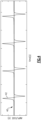
- Figure 4 is an example of the electrical signal as a result of teeth 38 passing the sensor 24. This plot shows the output signal, or amplitude, in volts on the vertical axis over time in seconds on the horizontal axis.
- the large peaks 42 correspond to a tooth 38 passing the sensor 24. In one example, the peaks 42 are greater than about 0.5 V.
- Figure 5 is a portion of an example electrical signal 40 from the sensor 24 which shows undesirable signal content between teeth 38, caused by a combination of vibration and electrical noise.
- Figure 6 is a portion of the electrical signal 40 over the ATS 20 startup cycle, where the tooth passing waveforms have been omitted using digital post-processing methods. In this example, it takes between about 80 and 90 seconds for the ATS 20 to ramp up from 0 RPM to a full speed.
- the digitally processed signal 40 reveals the amplitude of the noise signals 44 between the peaks 42. Some of this noise 44 corresponds to vibration of the gear 36. For example, as the ring gear 36 vibrates, the distance from the ring gear 36 to the sensor 24 varies, causing the shown varying amplitude in the signal 40.
- the noise 44 is the signal with an amplitude less than the peaks 42. In one example, the noise 44 has an amplitude of less than about 0.5 V. In a further example, the noise 44 has an amplitude of less than about 0.2 V.
- Figure 7 is a chart of the calculated speed of the ATS 20 in RPM over time. The plot is generated based on the detection of peaks 42 and the known space between the teeth 38. This plot shows a start cycle for the ATS 20. The speed of the ATS 20 starts at 0 RPM, and ramps up to about 5000 RPM over a period ofbetween about 80 and 90 seconds. Some turbine starters or other rotating components may have a longer ramp up period and/or different operating speeds.
- Figure 8 is a three dimensional plot 50 of the electrical signal 40 in the frequency domain.
- the electrical signal of Figures 4-6 shows amplitude and speed over time, respectively. Thus, both amplitude and speed are functions of time, and Figures 4-6 show a time domain signal.
- This signal is transformed into the frequency domain to view the frequencies that make up the signal.
- a Fourier Transform is used to convert the time domain signal into the frequency domain.
- a Fourier Transform decomposes a function of time into frequencies.
- the transformation into the frequency domain may be done using the known Fast Fourier Transform (FFT) algorithm.
- FFT Fast Fourier Transform
- the plot of Figure 8 shows the amplitude over time and across frequencies.
- the signal 40 must be gathered for all speeds of the ATS 20.
- the ramp up period is about 90 seconds.
- 90 seconds of signal 40 must be gathered to collect data for all speeds of the ATS 20.
- the component may go through all speeds in a shorter time, and thus a shorter time for the signal may be sufficient.
- the sensor 24 should be sampled at a rate of at least twice the frequency of the highest expected vibration frequency of the rotating components. This ensures sufficient data in the noise 44 of the signal 40 to provide meaningful information about vibrations of the ATS 20 in the frequency domain.
- the sensor 24 is sampled at a rate of at least about 15 kHz.
- the sensor 24 is sampled at a rate of at least about 30 kHz.
- the sensor 24 is sampled at a rate of between 200 kHz and 2,000 kHz.
- the frequency data of plot 50 provides information about the ATS 20.
- the various noise contributing sources in the plot 50 provide information about particular components within the ATS 20.
- the components within an ATS 20 have expected vibration behaviors, and deviations from these behaviors within plot 50 may indicate faults or unacceptable wear in the ATS 20.
- This group 52 corresponds to noise contributions from the ring gear 36, bearings, and output shaft, based on the detected frequencies.
- a series of peaks 54 at about 5000 Hz may be indicative of system or sensor resonance, since they are all about the same frequency for the entire time signal and are not a function of rotational speed.
- a series of peaks 56 corresponds to the meshing of the planet gear 34 and the sun gear 32.
- the series of peaks 58 corresponds to the meshing of the ring gear 36 and the planet gear 34.
- a fault or abnormality in the ATS 20 may be detected.
- a fault may indicate a component failure
- a fault may be a defect in the component
- a fault may be an abnormality in the component
- a fault may indicate wear on the component that suggests it may fail. That is, a fault or unacceptable wear detected may predict a failure of a component in the ATS 20 before it occurs.
- Unexpected peaks are any that do not show up on a plot for a good ATS 20 that is known to have no faults or defects. The location of any unexpected peaks may indicate which component within the ATS 20 has a fault.
- the plot 50 may reveal faults associated with the sun gear 32, ring gear 36, planet gear 34, shaft 39, or a bearing in the ATS 20.
- the plot 50 is compared to an expected signal that would be based on a healthy ATS 20 with no defects. Each individual frequency is analyzed to identify any deviance from the expected signal.
- Figure 9 summarizes an example method 70 of monitoring a rotating component.
- a processing system 26 collects data, and in particular an electrical signal 40, from the sensor 24 at 72. In one example, this occurs between flights during engine maintenance.
- the processing system 26 may collect data while the component is running, or may collect data stored previously.
- the processing system 26 removes high amplitude pulses from the signal 40 at 74. These pulses correspond to the teeth 38 passing the sensor 24, and are used to calculate speed. In addition to speed information, this signal 40 contains supplemental information regarding vibrations of the ATS 20.
- the signal 40 is then transformed from the time domain to the frequency domain at 76.
- the processing system 26 generates a three dimensional plot 50 of time, frequency, and amplitude at this step.
- the system 26 may generate another type of plot that displays time, frequency, and amplitude, such as a two dimensional plot with varying colors indicating frequency or amplitude over time at 76.
- the frequency domain signal is then compared to an expected signal at 78.
- the three dimensional plot 50 is analyzed to identify irregular or unexpected peaks in comparison with an expected signal at 80. Irregular peaks in the plot 50 suggest a component is vibrating more than expected, which may indicate a fault in the component.
- the three dimensional plot 50 is further analyzed to identify which component may have a fault at 82. Irregular peaks at particular times and frequencies may indicate a fault with a particular component within the ATS 20. If a fault in a particular component is detected, the component or the entire ATS 20 may be replaced at 84. Replacing a component may include repairing the component. This method provides a way to monitor health over time and to predict failures of the ATS 20.
- this method 70 is used during ground operations.
- the method 70 may be performed by hooking the processing system 26, such as a portable computer, to the sensor 24, and starting up the ATS 20.
- the portable computer then gathers and stores the electrical signal 40 generated by the sensor 24 for a period of time, such as 60-90 seconds. This method would be performed between flights as part of the engine maintenance.
- a data storage component is located on the aircraft that stores the electrical signal 40 gathered during a flight. This electrical signal data is then transferred to the processing system 26 after the flight, and the signal 40 is analyzed according to the above described method 70.
- a processing system 26 is located on the aircraft in addition to the onboard data collection system. The processing system 26 may be either dedicated or integrated with control or diagnostic electronics on the aircraft. The signal 40 is analyzed at each usage of the component, or at regular intervals of usage, using this method 70.
- Known air turbine starters 20 encounter large mechanical stresses while initiating engine rotation. Each start process causes wear on internal components, such as bearings, shafts, and gears. Wear may result in failed engine starts, flight delays and/or flight cancellations.
- Known ATS maintenance methods include keeping track of the length of time and/or number of start cycles an ATS 20 has done, and replacing components after a certain number of operating hours. If an ATS component fails before the expiration time, it may not be caught until a failed engine start.
- the disclosed monitoring method 70 may predict the failure of the air turbine starter 20 and/or any components of the ATS 20, and enables the premature replacement of the unit at a more conveniently scheduled time.
- the disclosed method of analyzing and monitoring a rotating component relies on the electrical signal generated by the existing speed sensors on the component, expanding the capabilities of existing sensor technology.
- the method monitors internal vibrations in the ATS, and enables operators to monitor individual components within the ATS without having to disassemble the ATS for inspection.
Landscapes
- Physics & Mathematics (AREA)
- General Physics & Mathematics (AREA)
- Engineering & Computer Science (AREA)
- Mechanical Engineering (AREA)
- Testing Of Devices, Machine Parts, Or Other Structures Thereof (AREA)
- Measurement Of Mechanical Vibrations Or Ultrasonic Waves (AREA)
Claims (9)
- Procédé de surveillance d'un composant rotatif, comprenant :collecter un signal électrique provenant d'un capteur disposé à proximité d'un composant rotatif d'un assemblage ;transformer le signal électrique d'un domaine temporel en un domaine fréquentiel ; etcomparer le signal électrique à un signal attendu ;déterminer s'il y a un défaut dans l'assemblage en se basant sur la comparaison avec le signal attendu ;déterminer une partie de l'assemblage contenant le défaut sur la base de la comparaison avec le signal attendu ; et/ou comprenant la détermination si le défaut correspond à un problème avec un système d'engrenage, un arbre ou un roulement ; etdans lequel le composant rotatif est un engrenage ayant au moins une dent ;dans lequel l'étape de collecte comprend la collecte de données à une fréquence d'au moins environ 30 kHz ; et/ou dans lequel l'étape de collecte comprend la collecte d'un signal électrique à partir d'une plage de vitesses du composant rotatif ; et/ou dans lequel l'étape de collecte comprend la collecte du signal électrique pendant une période de temps correspondant à un démarrage du composant fonctionnant dans toutes les conditions de vitesse de rotation ; etcréation d'un tracé tridimensionnel du signal électrique incluant le temps, la fréquence et l'amplitude du signal, et caractérisé par la suppression de toutes les impulsions d'amplitude correspondant à une dent passant le capteur du signal électrique avant l'étape de transformation.
- Procédé selon la revendication 1, dans lequel l'étape de comparaison comprend la comparaison d'une amplitude du signal électrique sur plusieurs fréquences avec le signal attendu.
- Procédé selon la revendication 1 ou 2, dans lequel l'engrenage comporte une pluralité de dents espacées autour d'une circonférence de l'engrenage.
- Procédé selon l'une quelconque des revendications précédentes, dans lequel l'assemblage est un démarreur de turbine à air.
- Procédé selon l'une quelconque des revendications précédentes, dans lequel l'étape de collecte comprend la collecte de données à une fréquence d'au moins deux fois la fréquence de rotation maximale du composant rotatif.
- Procédé selon l'une quelconque des revendications précédentes, dans lequel le capteur est un capteur de vitesse magnétique.
- Procédé selon l'une quelconque des revendications précédentes, dans lequel l'étape de transformation comprend la réalisation d'une transformée de Fourier.
- Système de surveillance d'un composant rotatif, dans lequel le système est configuré pour exécuter le procédé selon la revendication 1, le système comprenant :un démarreur à turbine à air avec un composant rotatif ;un capteur de vitesse magnétique (24) disposé à côté du composant rotatif du démarreur à turbine à air (20) ; etun processeur configuré pour collecter un signal provenant du capteur de vitesse magnétique (24) et transformer le signal d'un domaine temporel en un domaine fréquentiel.
- Système selon la revendication 8, dans lequel le processeur est configuré pour générer un tracé du signal dans le domaine fréquentiel.
Applications Claiming Priority (1)
| Application Number | Priority Date | Filing Date | Title |
|---|---|---|---|
| US16/369,592 US11148236B2 (en) | 2019-03-29 | 2019-03-29 | Prognostic monitoring and failure detection of rotating components |
Publications (2)
| Publication Number | Publication Date |
|---|---|
| EP3715821A1 EP3715821A1 (fr) | 2020-09-30 |
| EP3715821B1 true EP3715821B1 (fr) | 2025-01-01 |
Family
ID=68655314
Family Applications (1)
| Application Number | Title | Priority Date | Filing Date |
|---|---|---|---|
| EP19211122.7A Active EP3715821B1 (fr) | 2019-03-29 | 2019-11-25 | Surveillance de pronostic et détection de défaillances de composants rotatifs |
Country Status (2)
| Country | Link |
|---|---|
| US (1) | US11148236B2 (fr) |
| EP (1) | EP3715821B1 (fr) |
Families Citing this family (1)
| Publication number | Priority date | Publication date | Assignee | Title |
|---|---|---|---|---|
| US11790701B2 (en) * | 2021-05-20 | 2023-10-17 | General Electric Company | Systems and methods for monitoring component failure in a gear train based system |
Citations (2)
| Publication number | Priority date | Publication date | Assignee | Title |
|---|---|---|---|---|
| US20050284225A1 (en) * | 2004-06-28 | 2005-12-29 | Huageng Luo | System and method for monitoring the condition of a drive train |
| EP2684020B1 (fr) * | 2011-03-09 | 2019-04-24 | Rolls-Royce plc | Détection de rupture d'arbre |
Family Cites Families (5)
| Publication number | Priority date | Publication date | Assignee | Title |
|---|---|---|---|---|
| US6445995B1 (en) * | 2001-01-26 | 2002-09-03 | General Electric Company | Vibration sensing in gas turbine engine |
| US7392713B2 (en) | 2002-09-30 | 2008-07-01 | United Technologies Corporation | Monitoring system for turbomachinery |
| JP4657800B2 (ja) * | 2005-05-16 | 2011-03-23 | 本田技研工業株式会社 | 航空機用ガスタービン・エンジンの制御装置 |
| US7421349B1 (en) * | 2006-05-15 | 2008-09-02 | United States Of America As Represented By The Secretary Of The Navy | Bearing fault signature detection |
| US20180340475A1 (en) | 2017-05-26 | 2018-11-29 | Hamilton Sundstrand Corporation | Bowed rotor motoring control |
-
2019
- 2019-03-29 US US16/369,592 patent/US11148236B2/en active Active
- 2019-11-25 EP EP19211122.7A patent/EP3715821B1/fr active Active
Patent Citations (2)
| Publication number | Priority date | Publication date | Assignee | Title |
|---|---|---|---|---|
| US20050284225A1 (en) * | 2004-06-28 | 2005-12-29 | Huageng Luo | System and method for monitoring the condition of a drive train |
| EP2684020B1 (fr) * | 2011-03-09 | 2019-04-24 | Rolls-Royce plc | Détection de rupture d'arbre |
Also Published As
| Publication number | Publication date |
|---|---|
| US11148236B2 (en) | 2021-10-19 |
| EP3715821A1 (fr) | 2020-09-30 |
| US20200306900A1 (en) | 2020-10-01 |
Similar Documents
| Publication | Publication Date | Title |
|---|---|---|
| EP2305986B1 (fr) | Système pour faire fonctionner une turbine à gaz | |
| RU2449252C2 (ru) | Способ обнаружения повреждения опорного подшипника качения двигателя | |
| US11970949B2 (en) | Method and system for detecting a functional failure in a power gearbox and a gas turbo engine | |
| JP5562979B2 (ja) | 航空機ガスタービンエンジンの動作時に生じる振動現象を監視するための方法およびシステム | |
| US11939875B2 (en) | Gas turbine engine drive system health monitor | |
| US12517011B2 (en) | Method for monitoring a rotating machine in order to detect a fault in an aircraft bearing | |
| EP3361229A2 (fr) | Système et procédé de surveillance de la santé de la pale de rotor | |
| EP3217170A1 (fr) | Surveillance de l'état d'un moteur au moyen de détecteurs acoustiques | |
| RU2496018C2 (ru) | Способ и система для определения углового положения ротора турбореактивного двигателя | |
| RU2300116C2 (ru) | Способ диагностики электродвигателей переменного тока и связанных с ними механических устройств | |
| US20230314281A1 (en) | Methods and systems of monitoring a condition of a component of a gas turbine engine | |
| JP5722315B2 (ja) | ジェットエンジンの低圧燃料ポンプの不具合を検出するための方法および装置ならびに前記装置を備えたジェットエンジン | |
| EP3683410A2 (fr) | Détection d'un événement d'impact d'objet | |
| Courrech et al. | Condition monitoring of machinery | |
| US11148236B2 (en) | Prognostic monitoring and failure detection of rotating components | |
| US11790701B2 (en) | Systems and methods for monitoring component failure in a gear train based system | |
| EP4465003A1 (fr) | Identification d'une défaillance dans un capteur de couple/signal de couple pour système d'aéronef | |
| EP4303406A1 (fr) | Système et procédé de détermination de déplacement orbital du rotor | |
| US20240159608A1 (en) | System and method for determining torque in a turbomachine | |
| Huang | Vibration Testing of a Certain Turbojet Engine Using the Power Spectrum Analysis. | |
| US20250085307A1 (en) | Apparatus and methods for calculating an angular speed of a rotary component | |
| Wang | Phase information at tooth mesh frequency for gear crack diagnosis | |
| Zabriskie | Diagnostic Sonics for Gas Turbine Engines | |
| Kestner et al. | Correlation analysis of multiple sensors for industrial gas turbine compressor blade health monitoring | |
| Rahmanović et al. | DECOM-TT 2007 5-th IFAC INTERNATIONAL WORKSHOP ON TECHNOLOGY TRANSFER IN DEVELOPING COUNTRIES: AUTOMATION IN INFRASTRUCTURE CREATION |
Legal Events
| Date | Code | Title | Description |
|---|---|---|---|
| PUAI | Public reference made under article 153(3) epc to a published international application that has entered the european phase |
Free format text: ORIGINAL CODE: 0009012 |
|
| STAA | Information on the status of an ep patent application or granted ep patent |
Free format text: STATUS: THE APPLICATION HAS BEEN PUBLISHED |
|
| AK | Designated contracting states |
Kind code of ref document: A1 Designated state(s): AL AT BE BG CH CY CZ DE DK EE ES FI FR GB GR HR HU IE IS IT LI LT LU LV MC MK MT NL NO PL PT RO RS SE SI SK SM TR |
|
| AX | Request for extension of the european patent |
Extension state: BA ME |
|
| STAA | Information on the status of an ep patent application or granted ep patent |
Free format text: STATUS: REQUEST FOR EXAMINATION WAS MADE |
|
| 17P | Request for examination filed |
Effective date: 20210325 |
|
| RBV | Designated contracting states (corrected) |
Designated state(s): AL AT BE BG CH CY CZ DE DK EE ES FI FR GB GR HR HU IE IS IT LI LT LU LV MC MK MT NL NO PL PT RO RS SE SI SK SM TR |
|
| STAA | Information on the status of an ep patent application or granted ep patent |
Free format text: STATUS: EXAMINATION IS IN PROGRESS |
|
| 17Q | First examination report despatched |
Effective date: 20220126 |
|
| GRAP | Despatch of communication of intention to grant a patent |
Free format text: ORIGINAL CODE: EPIDOSNIGR1 |
|
| STAA | Information on the status of an ep patent application or granted ep patent |
Free format text: STATUS: GRANT OF PATENT IS INTENDED |
|
| INTG | Intention to grant announced |
Effective date: 20240913 |
|
| GRAS | Grant fee paid |
Free format text: ORIGINAL CODE: EPIDOSNIGR3 |
|
| GRAA | (expected) grant |
Free format text: ORIGINAL CODE: 0009210 |
|
| STAA | Information on the status of an ep patent application or granted ep patent |
Free format text: STATUS: THE PATENT HAS BEEN GRANTED |
|
| AK | Designated contracting states |
Kind code of ref document: B1 Designated state(s): AL AT BE BG CH CY CZ DE DK EE ES FI FR GB GR HR HU IE IS IT LI LT LU LV MC MK MT NL NO PL PT RO RS SE SI SK SM TR |
|
| REG | Reference to a national code |
Ref country code: GB Ref legal event code: FG4D |
|
| REG | Reference to a national code |
Ref country code: CH Ref legal event code: EP |
|
| REG | Reference to a national code |
Ref country code: DE Ref legal event code: R096 Ref document number: 602019064204 Country of ref document: DE |
|
| REG | Reference to a national code |
Ref country code: IE Ref legal event code: FG4D |
|
| REG | Reference to a national code |
Ref country code: LT Ref legal event code: MG9D |
|
| REG | Reference to a national code |
Ref country code: NL Ref legal event code: MP Effective date: 20250101 |
|
| REG | Reference to a national code |
Ref country code: AT Ref legal event code: MK05 Ref document number: 1756681 Country of ref document: AT Kind code of ref document: T Effective date: 20250101 |
|
| PG25 | Lapsed in a contracting state [announced via postgrant information from national office to epo] |
Ref country code: NL Free format text: LAPSE BECAUSE OF FAILURE TO SUBMIT A TRANSLATION OF THE DESCRIPTION OR TO PAY THE FEE WITHIN THE PRESCRIBED TIME-LIMIT Effective date: 20250101 |
|
| PG25 | Lapsed in a contracting state [announced via postgrant information from national office to epo] |
Ref country code: FI Free format text: LAPSE BECAUSE OF FAILURE TO SUBMIT A TRANSLATION OF THE DESCRIPTION OR TO PAY THE FEE WITHIN THE PRESCRIBED TIME-LIMIT Effective date: 20250101 |
|
| PG25 | Lapsed in a contracting state [announced via postgrant information from national office to epo] |
Ref country code: PL Free format text: LAPSE BECAUSE OF FAILURE TO SUBMIT A TRANSLATION OF THE DESCRIPTION OR TO PAY THE FEE WITHIN THE PRESCRIBED TIME-LIMIT Effective date: 20250101 |
|
| PG25 | Lapsed in a contracting state [announced via postgrant information from national office to epo] |
Ref country code: ES Free format text: LAPSE BECAUSE OF FAILURE TO SUBMIT A TRANSLATION OF THE DESCRIPTION OR TO PAY THE FEE WITHIN THE PRESCRIBED TIME-LIMIT Effective date: 20250101 |
|
| PG25 | Lapsed in a contracting state [announced via postgrant information from national office to epo] |
Ref country code: NO Free format text: LAPSE BECAUSE OF FAILURE TO SUBMIT A TRANSLATION OF THE DESCRIPTION OR TO PAY THE FEE WITHIN THE PRESCRIBED TIME-LIMIT Effective date: 20250401 Ref country code: IS Free format text: LAPSE BECAUSE OF FAILURE TO SUBMIT A TRANSLATION OF THE DESCRIPTION OR TO PAY THE FEE WITHIN THE PRESCRIBED TIME-LIMIT Effective date: 20250501 |
|
| PG25 | Lapsed in a contracting state [announced via postgrant information from national office to epo] |
Ref country code: HR Free format text: LAPSE BECAUSE OF FAILURE TO SUBMIT A TRANSLATION OF THE DESCRIPTION OR TO PAY THE FEE WITHIN THE PRESCRIBED TIME-LIMIT Effective date: 20250101 |
|
| PG25 | Lapsed in a contracting state [announced via postgrant information from national office to epo] |
Ref country code: LV Free format text: LAPSE BECAUSE OF FAILURE TO SUBMIT A TRANSLATION OF THE DESCRIPTION OR TO PAY THE FEE WITHIN THE PRESCRIBED TIME-LIMIT Effective date: 20250101 Ref country code: PT Free format text: LAPSE BECAUSE OF FAILURE TO SUBMIT A TRANSLATION OF THE DESCRIPTION OR TO PAY THE FEE WITHIN THE PRESCRIBED TIME-LIMIT Effective date: 20250502 |
|
| PG25 | Lapsed in a contracting state [announced via postgrant information from national office to epo] |
Ref country code: GR Free format text: LAPSE BECAUSE OF FAILURE TO SUBMIT A TRANSLATION OF THE DESCRIPTION OR TO PAY THE FEE WITHIN THE PRESCRIBED TIME-LIMIT Effective date: 20250402 Ref country code: BG Free format text: LAPSE BECAUSE OF FAILURE TO SUBMIT A TRANSLATION OF THE DESCRIPTION OR TO PAY THE FEE WITHIN THE PRESCRIBED TIME-LIMIT Effective date: 20250101 |
|
| PG25 | Lapsed in a contracting state [announced via postgrant information from national office to epo] |
Ref country code: AT Free format text: LAPSE BECAUSE OF FAILURE TO SUBMIT A TRANSLATION OF THE DESCRIPTION OR TO PAY THE FEE WITHIN THE PRESCRIBED TIME-LIMIT Effective date: 20250101 |
|
| PG25 | Lapsed in a contracting state [announced via postgrant information from national office to epo] |
Ref country code: CZ Free format text: LAPSE BECAUSE OF FAILURE TO SUBMIT A TRANSLATION OF THE DESCRIPTION OR TO PAY THE FEE WITHIN THE PRESCRIBED TIME-LIMIT Effective date: 20250101 |
|
| PG25 | Lapsed in a contracting state [announced via postgrant information from national office to epo] |
Ref country code: SE Free format text: LAPSE BECAUSE OF FAILURE TO SUBMIT A TRANSLATION OF THE DESCRIPTION OR TO PAY THE FEE WITHIN THE PRESCRIBED TIME-LIMIT Effective date: 20250101 |
|
| REG | Reference to a national code |
Ref country code: DE Ref legal event code: R097 Ref document number: 602019064204 Country of ref document: DE |
|
| PG25 | Lapsed in a contracting state [announced via postgrant information from national office to epo] |
Ref country code: SM Free format text: LAPSE BECAUSE OF FAILURE TO SUBMIT A TRANSLATION OF THE DESCRIPTION OR TO PAY THE FEE WITHIN THE PRESCRIBED TIME-LIMIT Effective date: 20250101 |
|
| PG25 | Lapsed in a contracting state [announced via postgrant information from national office to epo] |
Ref country code: DK Free format text: LAPSE BECAUSE OF FAILURE TO SUBMIT A TRANSLATION OF THE DESCRIPTION OR TO PAY THE FEE WITHIN THE PRESCRIBED TIME-LIMIT Effective date: 20250101 |
|
| PG25 | Lapsed in a contracting state [announced via postgrant information from national office to epo] |
Ref country code: IT Free format text: LAPSE BECAUSE OF FAILURE TO SUBMIT A TRANSLATION OF THE DESCRIPTION OR TO PAY THE FEE WITHIN THE PRESCRIBED TIME-LIMIT Effective date: 20250101 |
|
| PG25 | Lapsed in a contracting state [announced via postgrant information from national office to epo] |
Ref country code: EE Free format text: LAPSE BECAUSE OF FAILURE TO SUBMIT A TRANSLATION OF THE DESCRIPTION OR TO PAY THE FEE WITHIN THE PRESCRIBED TIME-LIMIT Effective date: 20250101 |
|
| PG25 | Lapsed in a contracting state [announced via postgrant information from national office to epo] |
Ref country code: RO Free format text: LAPSE BECAUSE OF FAILURE TO SUBMIT A TRANSLATION OF THE DESCRIPTION OR TO PAY THE FEE WITHIN THE PRESCRIBED TIME-LIMIT Effective date: 20250101 |
|
| PG25 | Lapsed in a contracting state [announced via postgrant information from national office to epo] |
Ref country code: SK Free format text: LAPSE BECAUSE OF FAILURE TO SUBMIT A TRANSLATION OF THE DESCRIPTION OR TO PAY THE FEE WITHIN THE PRESCRIBED TIME-LIMIT Effective date: 20250101 |
|
| PLBE | No opposition filed within time limit |
Free format text: ORIGINAL CODE: 0009261 |
|
| STAA | Information on the status of an ep patent application or granted ep patent |
Free format text: STATUS: NO OPPOSITION FILED WITHIN TIME LIMIT |
|
| 26N | No opposition filed |
Effective date: 20251002 |
|
| PGFP | Annual fee paid to national office [announced via postgrant information from national office to epo] |
Ref country code: DE Payment date: 20251022 Year of fee payment: 7 |
|
| PGFP | Annual fee paid to national office [announced via postgrant information from national office to epo] |
Ref country code: GB Payment date: 20251023 Year of fee payment: 7 |
|
| PGFP | Annual fee paid to national office [announced via postgrant information from national office to epo] |
Ref country code: FR Payment date: 20251022 Year of fee payment: 7 |