EP3715908B1 - Procédé et dispositif de mesure optique de distance - Google Patents
Procédé et dispositif de mesure optique de distance Download PDFInfo
- Publication number
- EP3715908B1 EP3715908B1 EP19165546.3A EP19165546A EP3715908B1 EP 3715908 B1 EP3715908 B1 EP 3715908B1 EP 19165546 A EP19165546 A EP 19165546A EP 3715908 B1 EP3715908 B1 EP 3715908B1
- Authority
- EP
- European Patent Office
- Prior art keywords
- particle cloud
- curve
- cloud
- measurement
- particle
- Prior art date
- Legal status (The legal status is an assumption and is not a legal conclusion. Google has not performed a legal analysis and makes no representation as to the accuracy of the status listed.)
- Active
Links
Images


Classifications
-
- G—PHYSICS
- G01—MEASURING; TESTING
- G01S—RADIO DIRECTION-FINDING; RADIO NAVIGATION; DETERMINING DISTANCE OR VELOCITY BY USE OF RADIO WAVES; LOCATING OR PRESENCE-DETECTING BY USE OF THE REFLECTION OR RERADIATION OF RADIO WAVES; ANALOGOUS ARRANGEMENTS USING OTHER WAVES
- G01S7/00—Details of systems according to groups G01S13/00, G01S15/00, G01S17/00
- G01S7/48—Details of systems according to groups G01S13/00, G01S15/00, G01S17/00 of systems according to group G01S17/00
- G01S7/483—Details of pulse systems
- G01S7/486—Receivers
- G01S7/487—Extracting wanted echo signals, e.g. pulse detection
-
- G—PHYSICS
- G01—MEASURING; TESTING
- G01S—RADIO DIRECTION-FINDING; RADIO NAVIGATION; DETERMINING DISTANCE OR VELOCITY BY USE OF RADIO WAVES; LOCATING OR PRESENCE-DETECTING BY USE OF THE REFLECTION OR RERADIATION OF RADIO WAVES; ANALOGOUS ARRANGEMENTS USING OTHER WAVES
- G01S7/00—Details of systems according to groups G01S13/00, G01S15/00, G01S17/00
- G01S7/48—Details of systems according to groups G01S13/00, G01S15/00, G01S17/00 of systems according to group G01S17/00
- G01S7/483—Details of pulse systems
- G01S7/486—Receivers
- G01S7/4865—Time delay measurement, e.g. time-of-flight measurement, time of arrival measurement or determining the exact position of a peak
- G01S7/4866—Time delay measurement, e.g. time-of-flight measurement, time of arrival measurement or determining the exact position of a peak by fitting a model or function to the received signal
-
- G—PHYSICS
- G01—MEASURING; TESTING
- G01S—RADIO DIRECTION-FINDING; RADIO NAVIGATION; DETERMINING DISTANCE OR VELOCITY BY USE OF RADIO WAVES; LOCATING OR PRESENCE-DETECTING BY USE OF THE REFLECTION OR RERADIATION OF RADIO WAVES; ANALOGOUS ARRANGEMENTS USING OTHER WAVES
- G01S17/00—Systems using the reflection or reradiation of electromagnetic waves other than radio waves, e.g. lidar systems
- G01S17/02—Systems using the reflection of electromagnetic waves other than radio waves
- G01S17/06—Systems determining position data of a target
- G01S17/08—Systems determining position data of a target for measuring distance only
-
- G—PHYSICS
- G01—MEASURING; TESTING
- G01S—RADIO DIRECTION-FINDING; RADIO NAVIGATION; DETERMINING DISTANCE OR VELOCITY BY USE OF RADIO WAVES; LOCATING OR PRESENCE-DETECTING BY USE OF THE REFLECTION OR RERADIATION OF RADIO WAVES; ANALOGOUS ARRANGEMENTS USING OTHER WAVES
- G01S17/00—Systems using the reflection or reradiation of electromagnetic waves other than radio waves, e.g. lidar systems
- G01S17/02—Systems using the reflection of electromagnetic waves other than radio waves
- G01S17/06—Systems determining position data of a target
- G01S17/08—Systems determining position data of a target for measuring distance only
- G01S17/10—Systems determining position data of a target for measuring distance only using transmission of interrupted, pulse-modulated waves
-
- G—PHYSICS
- G01—MEASURING; TESTING
- G01S—RADIO DIRECTION-FINDING; RADIO NAVIGATION; DETERMINING DISTANCE OR VELOCITY BY USE OF RADIO WAVES; LOCATING OR PRESENCE-DETECTING BY USE OF THE REFLECTION OR RERADIATION OF RADIO WAVES; ANALOGOUS ARRANGEMENTS USING OTHER WAVES
- G01S17/00—Systems using the reflection or reradiation of electromagnetic waves other than radio waves, e.g. lidar systems
- G01S17/88—Lidar systems specially adapted for specific applications
- G01S17/93—Lidar systems specially adapted for specific applications for anti-collision purposes
- G01S17/931—Lidar systems specially adapted for specific applications for anti-collision purposes of land vehicles
-
- G—PHYSICS
- G01—MEASURING; TESTING
- G01S—RADIO DIRECTION-FINDING; RADIO NAVIGATION; DETERMINING DISTANCE OR VELOCITY BY USE OF RADIO WAVES; LOCATING OR PRESENCE-DETECTING BY USE OF THE REFLECTION OR RERADIATION OF RADIO WAVES; ANALOGOUS ARRANGEMENTS USING OTHER WAVES
- G01S7/00—Details of systems according to groups G01S13/00, G01S15/00, G01S17/00
- G01S7/48—Details of systems according to groups G01S13/00, G01S15/00, G01S17/00 of systems according to group G01S17/00
- G01S7/481—Constructional features, e.g. arrangements of optical elements
-
- G—PHYSICS
- G01—MEASURING; TESTING
- G01S—RADIO DIRECTION-FINDING; RADIO NAVIGATION; DETERMINING DISTANCE OR VELOCITY BY USE OF RADIO WAVES; LOCATING OR PRESENCE-DETECTING BY USE OF THE REFLECTION OR RERADIATION OF RADIO WAVES; ANALOGOUS ARRANGEMENTS USING OTHER WAVES
- G01S7/00—Details of systems according to groups G01S13/00, G01S15/00, G01S17/00
- G01S7/48—Details of systems according to groups G01S13/00, G01S15/00, G01S17/00 of systems according to group G01S17/00
- G01S7/481—Constructional features, e.g. arrangements of optical elements
- G01S7/4811—Constructional features, e.g. arrangements of optical elements common to transmitter and receiver
Definitions
- the invention relates to a method and a device for optical distance measurement.
- LIDAR Light Detection and Ranging
- devices comprise a transmitter unit for sending out measuring pulses and a receiver unit for receiving reflected measuring pulses that have been reflected from objects within a measuring range. Based on the time of flight principle, the distance to the objects from which the measuring pulses were reflected is determined using the speed of light.
- a point cloud is obtained in which each point represents a single measurement, i.e. the reception of a transmitted and reflected measurement pulse.
- the quality of such a point cloud suffers greatly in difficult weather conditions, such as fog, dust, spray, etc. This is because the reflections on the particles and their associated points in the LIDAR point cloud are incorrectly recognized as object reflections. Depending on the density of the particles, this can lead to the complete failure of the device.
- DE 10 2012 112987 B3 discloses an optoelectronic sensor and a method for detecting and determining the distance of objects.
- US 2014/0324266 A1 describes an apparatus and method for determining weather conditions using on-board vehicle sensors.
- the devices for measuring distance known from the state of the art are not themselves able to recognize that they are in a particle cloud. As a result, a particle cloud is incorrectly recognized by the device as an object. This reduces the quality of the time of flight measurement. However, since the device does not recognize this, the result of a time of flight measurement that is degraded by a particle cloud is treated with the same level of certainty, i.e. with the same level of confidence, as a measurement under conditions without a particle cloud. An assessment of the quality of the resulting point cloud as a result of the time of flight measurement can only be made in downstream computing units that evaluate the data provided over several time intervals.
- the present invention is based on the object of further developing a method and a device for optical distance measurement in such a way that the reflection of measuring pulses on a particle cloud can be distinguished from a reflection on an object.
- the above-mentioned task is solved by a method for optical distance measurement, which includes carrying out several time-of-flight measurements.
- a runtime measurement includes the transmission of at least one measuring pulse, in particular exactly one or a plurality of measuring pulses, by means of a transmitting unit, as well as the reflection of at least one transmitted measuring pulse, in particular of transmitted measuring pulses, on a particle cloud or on at least one object, and the reception of at least one measuring pulse, in particular of reflected measuring pulses, by means of a receiving unit.
- the method includes the generation of a point cloud based on the runtime measurement.
- the point cloud is a result of the runtime measurement.
- the method can preferably determine the transit time of each transmitted, reflected and received measuring pulse.
- the method also includes in particular the generation of a histogram in which the received optical power (or a corresponding electronic signal based on the measured optical power) is plotted against the determined transit time.
- the determined transit time can be averaged from several measuring pulses. A histogram with the averaged values can then also be generated.
- each reflected measurement pulse received by the receiving unit results in a point cloud, preferably in a 2D or 3D local coordinate system.
- a point cloud is thus obtained as a result of a runtime measurement.
- the determined runtime of several received and reflected measurement pulses can be averaged so that they together represent a point of a point cloud.
- the method includes generating a backscatter curve based on the time-of-flight measurement, wherein the method includes evaluating the backscatter curve for object recognition of at least one object and/or at least one particle cloud on which at least one measurement pulse was reflected.
- the method includes providing a sensitivity curve for evaluating the backscatter curve, wherein the evaluation of the backscatter curve includes determining a correlation between the sensitivity curve and the backscatter curve in order to use the time-of-flight measurements to determine whether a particle cloud is located in a measurement area measured using the time-of-flight measurements and to assign a particle cloud feature to each time-of-flight measurement.
- the term "measured measurement area" is to be understood in particular as the area that the measurement pulse of the time-of-flight measurement passed through.
- the determination of the correlation serves to establish whether there is a particle cloud in a measuring area measured using the runtime measurements. In other words, it is determined whether a device for carrying out the method is located in and/or in front of a particle cloud.
- the method advantageously includes determining using each runtime measurement whether a particle cloud is located in the measuring area and assigning a particle cloud feature to the runtime measurement.
- particle cloud feature refers in particular to a particle cloud status and/or a particle cloud probability.
- the particle cloud feature is determined based on the correlation determined.
- a particle cloud status could indicate whether the correlation indicates that a particle cloud is in the measurement area or not. The status could thus be available as dual yes/no information. For example, the status could be "yes” if the correlation exceeds a previously set threshold and "no" if it is below it.
- a particle cloud probability can be determined. This could be understood as a confidence measure of the fact that measurement pulses were reflected by a particle cloud.
- the method can thus determine a confidence measure between 0 and 100%, where 100% means that the correlation is very high and it can therefore be assumed that measurement pulses were reflected by a particle cloud, while 0% means that the correlation is negligible and it can therefore be assumed that no measurement pulse was reflected by a particle cloud.
- the confidence measure is determined on the basis of the determined correlation.
- the determination of the correlation serves to prevent a particle cloud from being falsely identified as an object.
- optical distance measurement is to be understood in such a way that distances are determined using optical signals, in this case optical measuring pulses.
- distance is to be understood as a distance.
- the distance covered by the measuring pulse is to be understood as the distance between the transmitting unit that sent out the measuring pulse and the reflection object that reflected it, plus the distance between the reflection object and the receiving unit that received the corresponding reflected measuring pulse.
- the reflected measuring pulses each represent backscatter signals of the transmitted measuring pulses.
- reflection object can be understood as an object and/or a particle cloud.
- the method is used in driverless navigation of vehicles, especially automobiles.
- the method can be used for autonomous
- the method can also be used to assist a driver of a vehicle. For this purpose, the distances to all reflective objects that are in a measuring area are determined.
- a measuring pulse is in particular an optical, in particular electromagnetic, signal.
- the measuring pulse is advantageously a light pulse, i.e. a pulse with a wavelength that is not in the range visible to the human eye. Invisible infrared is preferably used for safety reasons.
- a measuring pulse preferably has a pulse width so that the measuring pulse can be understood as a time-limited portion of electromagnetic radiation. Since the measuring pulse is an electromagnetic signal and the speed of the measuring pulse is therefore known, the running time of a measuring pulse can be used to determine the distance the measuring pulse has covered in the running time using the speed of light.
- the receiving unit may comprise at least one detector, for example a photodetector, in particular an optical detector.
- the receiving unit may comprise a plurality of receiving elements, which preferably operate in linear or Geiger mode.
- the receiving elements operating in linear mode may in particular be avalanche photodiodes, PN photodiodes, PIN diodes or photomultipliers, while the receiving elements operating in Geiger mode are preferably single-photon avalanche diodes (SPADs). In the latter, each photon is measured individually and a communication is made via the histogram obtained.
- SBADs single-photon avalanche diodes
- each photon is measured individually and a communication is made via the histogram obtained.
- the term "receiving element" refers in particular to pixels.
- the transmitting unit can comprise a plurality of transmitting elements, each of which is formed by a laser.
- the transmitting unit is to be understood as a "transmitting matrix", i.e. as an array of transmitting elements
- the receiving unit is to be understood as a receiving matrix, i.e. as an array of receiving elements.
- a matrix can be understood in particular as a three-dimensional, in particular plate-shaped, body, on one surface of which the corresponding elements, transmitting elements or receiving elements, are arranged.
- particle cloud refers in particular to an accumulation of particles in air.
- a particle cloud is an aerosol.
- these are solid and/or liquid, finely distributed suspended particles in air.
- they can be liquid, finely distributed liquid droplets in air, for example mist or spray.
- They can also be solid, finely distributed dust particles, for example dust or smog.
- a particle cloud can also be understood to be an exhaust cloud from the exhaust of a vehicle, which includes in particular oil and soot smoke.
- the dimensions, in particular the diameter, of the particles is typically less than 1 mm, in particular less than 100 ⁇ m, most preferably less than 50 ⁇ m.
- an object within the meaning of the invention is not an aerosol. It is primarily a solid or liquid body.
- backscatter curve is to be understood as a curve that can be used to determine the optical power received by the receiving unit in relation to the determined transit time.
- the backscatter curve is the histogram generated from a transit time measurement.
- the received optical power is preferably converted into an electronic signal that is plotted in relation to the determined transit time.
- a corresponding electronic signal and the transit time of at least one transmitted and received measuring pulse are therefore preferably determined on the basis of the measured optical power, with the at least one corresponding pair of values being plotted on a coordinate system with the electronic signal as the y-axis and the transit time as the x-axis.
- the backscatter curve is the raw signal of the time-of-flight measurement.
- the raw signal is the analog or digital representation of the reflected optical signal, in other words the electronic signal into which the received reflected optical power is converted.
- the backscatter curve is a result of all transmitted, reflected and received measurement pulses of the same time-of-flight measurement.
- a time-of-flight measurement primarily involves the transmission of exactly one measurement pulse.
- time-of-flight information from a large number of photons is taken into account, so that the histogram generated from a single measurement pulse represents the backscatter curve. This is because individual photons are reflected by closer particles in the particle cloud, while other photons are reflected by particles further away.
- the transit time measurement involves sending out a large number of measurement pulses, with the histogram showing the average transit times.
- the histogram can show the backscatter curve.
- the term "sensitivity curve" of the receiving unit refers in particular to the sensitivity curve of the receiving unit, in particular of a device for carrying out the method.
- the sensitivity curve describes, among other things, how sensitively the receiving unit or individual receiving elements of the receiving unit react to the distance from the receiving unit to which a reflective object is located.
- the sensitivity curve describes the influence of the distance of the reflective object, at which a measuring pulse is reflected, on the optical power that is detected, assuming the same optical power of the measuring pulse.
- Other factors can also influence the sensitivity curve, such as the divergences between a transmitting and receiving unit of a device and/or how far apart a transmitting and receiving unit are from each other.
- the sensitivity curve is therefore receiving unit-specific, in particular device-specific or sensor-specific.
- the sensitivity curve represents an overall increase, in other words a "peak", in a coordinate system with the electronic signal into which the optical power has been converted on the y-axis and the time of flight on the x-axis, preferably with a rising edge and a falling edge.
- the shape of the sensitivity curve results from the fact that the optical power of the backscatter signal is naturally expected to decrease with increasing distance. However, due to the influencing factors mentioned above, the maximum power is only achieved at a certain distance from the receiving unit.
- the method may include providing a single common sensitivity curve for the entire receiving unit and/or the entire device.
- the method may further include providing a sensitivity curve for each receiving element of the receiving unit.
- the method may advantageously generate a backscatter curve for each individual receiving element. In other words, each time-of-flight measurement may be assigned to a receiving element. Based on the backscatter curve and the sensitivity curve, the correlation for each receiving element may be determined and optionally averaged.
- the receiving elements of the receiving unit e.g. only one receiving element, can be used for particle cloud detection.
- the number of receiving elements used for particle cloud detection is smaller than the total number of receiving elements.
- the evaluation includes determining a correlation between the sensitivity curve and the backscatter curve.
- the advantage here is that the sensitivity curve has very similar characteristics to a section of a backscatter curve that is due to a reflection from a particle cloud.
- reflections are typically received from all distances to a device for carrying out the method that includes the particle cloud.
- this type of reflection is represented by the sensitivity curve, which shows how a receiving unit, preferably a device for carrying out the method, reacts to reflections from all different distances to a receiving unit, in particular to a device for carrying out the method.
- the course of the sensitivity curve and the section of a backscatter curve that is due to reflection from a particle cloud are therefore very similar.
- the shape of the curves is similar.
- correlation refers to a relationship between the backscatter curve and the sensitivity curve.
- the correlation is a measure of how similar at least one section of the backscatter curve and the sensitivity curve are, especially their shape. This section of the backscatter curve could correspond to the reflection from a particle cloud.
- the backscatter curve comprises, above all, at least one elevation, preferably several elevations.
- An elevation is present in particular when it stands out clearly from the noise of the backscatter curve, in other words from a corresponding deviation of the values of the optical power for the same transit time.
- An elevation is present when the elevation has a maximum optical power that preferably corresponds to at least twice the noise.
- the determination of the correlation serves to determine whether at least one section of the backscatter curve is similar to the sensitivity curve.
- section refers in particular to a part of the backscatter curve. which includes an increase in the backscatter curve.
- the correlation determined can be used to determine whether a particle cloud was measured during the time-of-flight measurement, in other words, whether measurement pulses from the time-of-flight measurement were reflected by a particle cloud.
- the method comprises the detection of a particle cloud and preferably the determination of a confidence measure for the detection of the particle cloud.
- the confidence measure is determined on the basis of the determined correlation.
- the confidence measure is a measure of the quality, in other words the credibility, of the detection of a particle cloud.
- the method comprises outputting a message regarding the at least one particle cloud feature.
- An output could, for example, be as follows: "Particle cloud status "yes” with a particle cloud probability of 75%”.
- the method includes carrying out a plurality of runtime measurements, wherein the particle cloud status of the runtime measurement is preferably "yes” or “no” in each case.
- the method includes setting a first threshold, wherein a particle cloud is detected when the number of runtime measurements with a particle cloud status of "yes" exceeds the first threshold.
- the first threshold can be defined as “1” so that, for example, a particle cloud is detected even with a runtime measurement with a particle cloud status of "yes”.
- the first threshold can be defined such that it is 10%, most preferably 20%, of all runtime measurements.
- the method may comprise setting a second threshold for the particle cloud probability, wherein a particle cloud is detected when the number of runtime measurements with a particle cloud probability above the second threshold exceeds the first threshold.
- the confidence measure is represented in particular as a probability.
- the method thus determines a confidence measure between 0 and 100%, with 100% meaning that the correlation is very high and the method is therefore very certain that measurement pulses were reflected by a particle cloud, while 0% means that the Correlation is negligible and it can therefore be assumed that no measurement pulse was reflected by a particle cloud.
- the method comprises outputting a message regarding the detection of a particle cloud and the confidence level determined.
- An output could, for example, be as follows: "A particle cloud was detected here with a confidence level of 75%.”
- the correlation is determined using a convolution of the backscatter curve with the sensitivity curve.
- the determination of the correlation can include a Fourier transformation, in particular a fast Fourier transformation.
- the determination of the correlation can also include the use of an optimal filter adapted to the sensitivity curve. This can be taught beforehand, the method comprising teaching the optimal filter using a neural network.
- the optimal filter can be taught using an autoencoder.
- the optimal filter can be taught using deep learning.
- the method may comprise simulating the sensitivity curve.
- the sensitivity curve can be measured.
- at least one object can be placed at different distances from a receiving unit, without the presence of a particle cloud, with the receiving unit receiving the reflected optical power and converting it into a corresponding electronic signal.
- this results in the course of the electronic signal as a measure of the reflected optical power as a function of the distance or the propagation time and thus the sensitivity curve.
- a measurement in particular end-of-line, has the advantage that it also includes the electrical behavior of the receiving unit, in particular the device for carrying out a method, in other words the sensor, as well as the sensor-specific mechanical and optical deviations.
- a simulation involves a lot more effort and could be incomplete.
- a measurement of the sensitivity curve can be carried out specifically for the type of device, in other words sensor, used to carry out the method.
- sensor type refers primarily to the type of sensor, influenced by the model and the corresponding technology, e.g. influenced by the type of detector and/or the optics and/or the measuring principle.
- the method includes taking into account a possible scaling of the backscatter curve depending on the density of a particle cloud when determining the correlation.
- the reflection from a particle cloud depends on its density.
- the denser the particle cloud the higher the signal, and thus indirectly the optical power, in the backscatter curve.
- the backscatter curve can be scaled with a factor that takes the density of the particle cloud into account.
- the denser the particle cloud the more the backscatter curve is compressed in the direction of the x-axis. This scaling can change the course of the backscatter curve in relation to the sensitivity curve.
- the height of the increase in the backscatter curve which is attributable to a reflection from a particle cloud, is therefore dependent on its density
- the basic shape is nevertheless so similar to that of the sensitivity curve that even with particle clouds of different densities, a correlation can be determined that indicates that the reflection is the reflection from a particle cloud.
- the method can include detecting a density of the particle cloud and preferably determining a confidence measure for detecting the density.
- the method can include taking the height of a peak into account.
- the evaluation includes an assessment of the maximum height of the increase in the backscatter curve that was assigned to the reflection on a particle cloud, from which the density of the particle cloud can be deduced.
- the confidence measure is a measure of the quality, in other words the credibility, of the detected density.
- the confidence measure for the detection of the density is represented in particular as a probability.
- the method thus determines a confidence measure between 0 and 100%, with 100% meaning that the evaluation is very clearly in line with the detected Density can be concluded and the method is therefore very certain that the particle cloud has exactly this density, while 0% means that the evaluation was not clear and it is therefore very uncertain whether the particle cloud really has the detected density.
- the method comprises outputting a message regarding the detection of the density and the determined confidence level.
- An output could be, for example, as follows: "The density of the particle cloud comprises X particles per volume with a confidence level of 80%”.
- a message can be directed primarily to a driver of a vehicle, the vehicle being navigated using the present method and/or the driver being assisted using the present method.
- the output serves in particular to inform the driver that the vehicle is in a particle cloud and/or is moving toward a particle cloud.
- the method can include carrying out at least one further measurement to measure measurement data of at least one further sensor modality.
- sensor modality is in particular the German term for the English term "sensor modality”.
- the sensor modality is a sensor category. Sensors therefore differ in particular in terms of the sensor modality or sensor category.
- the sensor modality determines the measurement method with which the measurement data is generated.
- the sensor modality is preferably lidar, radar, image or ultrasound. This means that the corresponding sensor of the modality is preferably a lidar sensor, a radar sensor, an image sensor, in particular a camera, or an ultrasound sensor.
- the method preferably comprises the measurement of radar measurement data, image data and/or ultrasound data.
- the method may comprise determining a confidence measure for the detection of a particle cloud for the measurement data of each sensor modality, wherein the method further comprises comparing the determined confidence measures.
- an overall confidence measure is determined, into which the confidence measures of the individual sensor modalities are taken into account. This overall confidence measure can be output together with a message.
- the corresponding runtime measurement can be assigned to each point of a point cloud.
- the method according to the invention comprises determining a confidence measure for the runtime measurement, in particular for the corresponding points of a point cloud, taking into account the detection of a particle cloud.
- the confidence measure can be understood as the quality of a time-of-flight measurement, i.e. as the quality or the probability that its results are degraded, in particular due to reflection from a particle cloud.
- the present method thus enables an assessment of the quality of the time-of-flight measurement.
- the confidence measure for the time-of-flight measurement that is degraded due to the particle cloud is adjusted.
- the confidence measure is adjusted compared to a time-of-flight measurement in which no particle cloud was detected.
- the confidence measure is determined depending on the detection of a particle cloud and/or the detection of its density and/or the confidence measure for the detection of the particle cloud and/or the confidence measure for the detection of the density.
- the method may comprise creating a 3D depth map that describes the distances and/or directions at which a particle cloud and/or the detected objects are arranged relative to a device for carrying out the method.
- the steps described above can preferably be carried out for each of the measurements.
- the confidence measure for the runtime measurement is assigned to the corresponding points of a point cloud.
- the method comprises generating a point cloud that includes points from different runtime measurements. By assigning the confidence measures, the point cloud can contain points with different confidence measures.
- the method in particular comprises object recognition, wherein the method comprises a distinction between objects and particle clouds.
- object recognition elevations in the backscatter curve are observed and classified.
- the information about the similarity i.e. the correlation between the backscatter curve and the sensitivity curve, can be relevant. If there is a sufficient correlation between an elevation and the sensitivity curve, it can be assumed that the elevation does not result from reflection on an object, but from reflections on a particle cloud.
- the method in particular comprises a classification of elevations as a particle cloud or an object, wherein the method further preferably comprises a determination of a confidence measure for each classification.
- the confidence measure is determined on the basis of the determined correlation.
- the confidence measure is a measure of the quality, in other words the credibility, of the classification.
- the confidence measure is presented in particular as a probability.
- the method thus determines a confidence measure between 0 and 100%, with 100% meaning that the correlation clearly indicates that this is the respective classified reflection object, while 0% means that the correlation is not clear, so it is not certain whether the increase is due to the reflection from a particle cloud or an object.
- the method includes outputting a message regarding the classification and the determined confidence level.
- An output could be as follows, for example: "Here, an object was detected at distance x with a confidence level of 60%.”
- the present invention comprises a device for distance measurement, wherein the device comprises a receiving unit and a transmitting unit for carrying out a plurality of runtime measurements.
- the transmitting unit serves to transmit at least one measuring pulse, in particular a plurality of measuring pulses, while the receiving unit serves to receive at least one reflected measuring pulse, in particular reflected measuring pulses that were previously transmitted and were reflected by a particle cloud or by at least one object.
- the device is designed to carry out a method described above.
- the device comprises in particular an evaluation unit which is designed to evaluate the backscatter curve for object detection, in particular of at least one object and/or a particle cloud on which the measurement pulses were reflected. Furthermore, the evaluation unit is designed to determine a correlation between the sensitivity curve and the backscatter curve. Furthermore, the evaluation unit can be designed for object detection and/or recognition of a particle cloud and/or recognition of objects and/or classification of the density of a detected particle cloud and/or output of feedback and/or determination of a confidence measure and/or differentiation of particle clouds and objects.
- the evaluation unit can comprise digital signal processors, e.g. ASICs and/or FPGAs and/or microprocessors, etc.
- the device is primarily a LIDAR device, in particular a scanning LIDAR device or a flash LIDAR device.
- the device comprises a LIDAR sensor.
- the device can comprise a radar sensor, an image sensor, in particular a camera, or an ultrasonic sensor.
- the device can be a driver assistance system.
- the invention comprises a computer program product comprising a computer-readable storage medium on which a program is stored which enables a computer, after it has been loaded into the memory of the computer, to carry out a method described above, optionally in interaction with a device described above.
- the invention relates to a computer-readable storage medium on which a program is stored which, after it has been loaded into the memory of the computer, enables a computer to carry out a method described above, optionally in interaction with a device described above.
- Figure 1 shows a process diagram of a method (100) according to the invention for measuring distance.
- the method comprises carrying out (101) at least one transit time measurement, wherein a transit time measurement comprises the transmission (102) of at least one measuring pulse by means of a transmission unit (12), the reflection (103) of at least one transmitted measuring pulse and the reception (104) of at least one reflected measuring pulse by means of a reception unit (11).
- the method can further comprise carrying out several transit time measurements.
- the method further comprises the generation (105) of a backscatter curve (20) based on the time-of-flight measurement, as well as the provision (106) of a sensitivity curve (21).
- the sensitivity curve (21) can be simulated (107) and/or measured (108).
- the method (100) further comprises the evaluation (109) of the backscatter curve (20) for object recognition (113).
- the evaluation (109) comprises the determination (110) of a correlation between the sensitivity curve (21) and the backscatter curve (20).
- the correlation can be determined by means of a convolution (111) and/or by using (112) an optimal filter.
- the determination (110) of the correlation serves to determine, by means of the at least one time-of-flight measurement, whether a particle cloud (27) is arranged in a measurement area measured by means of the time-of-flight measurement and to assign a particle cloud feature to the time-of-flight measurement (120).
- the method comprises such an assignment (120).
- the evaluation (109) can include object detection (113).
- the method (100) can include the detection (114) of a particle cloud (27).
- the method can primarily comprise setting a first threshold, wherein a particle cloud is detected (114) when the number of runtime measurements with a particle cloud status of "yes" exceeds the first threshold.
- the method can comprise setting a second threshold for the particle cloud probability, wherein a particle cloud is detected (114) when the number of runtime measurements with a particle cloud probability above the second threshold exceeds the first threshold.
- the method (100) can determine a confidence measure for the detection (114a). Furthermore, the method (100) can comprise the detection (115) of a density of the particle cloud and the determination (115a) of a confidence measure for the detection of the density.
- the method (100) can comprise the detection (116) of objects, wherein a distinction can be made between particle clouds (27) and objects (26) (118). Furthermore, the method can comprise an output (117) of a message regarding the detection of a particle cloud and/or its density.
- the evaluation (109) of the backscatter curve (20) can comprise the creation (119) of a 3D depth map that indicates at which distances a detected particle cloud and/or detected objects (26) are arranged on a device (10) for carrying out the method (100).
- Figure 2 shows a sensitivity curve (21).
- the sensitivity curve is a representation of an electronic signal (30), into which the received optical power has been converted and which is thus considered an indirect measure of the optical power, over the propagation time (31).
- Figure 2 shows on the one hand how a sensitivity curve (21) was measured by individual measurements (22).
- the individual measurements (22) are based on measurements in which an object is placed at different distances and thus different travel times (31) to a receiving unit (11).
- the optical power is measured after reflection from the object and converted into an electronic signal (30) that is plotted against the travel time.
- the sensitivity curve (21) is thus obtained by interpolation.
- the sensitivity curve (21) can also be simulated. The same course is then obtained.
- FIG. 3 shows a device (10) according to the invention for carrying out a method (100) according to the invention.
- the device (10) according to the invention comprises a receiving unit (11) and a transmitting unit (12).
- the transmitting unit (12) is used to send out measuring pulses, while the receiving unit (11) is used to receive the reflected measuring pulses.
- the receiving unit (11) and the transmitting unit (12) are used to carry out transit time measurements.
- the evaluation unit (13) is used to evaluate the backscatter curve as a result of the transit time measurement, specifically with the aid of the sensitivity curve (21).
- the device (10) also has a control unit (14) which is designed to control the receiving unit (11), the transmitting unit (12) and/or the evaluation unit (13) accordingly.
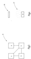
- Figure 4 shows a device (10) according to the invention, in front of which a particle cloud (27) is located in the immediate vicinity and an object (26) is located at a distance from the device (10) and the particle cloud (27).
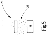
- Figure 5 shows a device (10) according to the invention, in front of which a particle cloud (27) is located in the immediate vicinity.
- An object (26) is located in the particle cloud.
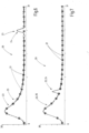
- the corresponding backscatter curve (20) obtained after carrying out a runtime measurement based on the Figure 4 is in Figure 6 can be seen.
- the backscatter curve (20) is an indirect representation of the optical power over the transit time (31), in which an electronic signal (30) into which the received optical power is converted is plotted against the transit time.
- Several elevations (23) can be seen in the backscatter curve (20). Such elevations (23) are typically assigned to an object.
- the sensitivity curve (21) is also shown in dotted form.
- the left elevation (23) is classified as the result of a reflection from a particle cloud (27). This is therefore an elevation (25) of the backscatter curve (20) due to a reflection from a particle cloud (27).
- no correlation at least no sufficient correlation, can be determined so that the elevation can be recognized with sufficient probability as an elevation (24) due to reflection from an object.
- particle clouds (27) can be clearly distinguished from objects (26).
- the backscatter curve (20) obtained after performing a runtime measurement based on the Figure 5 shows Figure 7 . Because the object (26) is located within the particle cloud (27), the elevation (23) that is attributable to the object is arranged on the elevation that results from the particle cloud. The signals have added together at this point, so that even if an object (26) is located within a particle cloud (27), it can be clearly recognized and distinguished from the particle cloud (27).
Landscapes
- Physics & Mathematics (AREA)
- Engineering & Computer Science (AREA)
- Electromagnetism (AREA)
- Computer Networks & Wireless Communication (AREA)
- General Physics & Mathematics (AREA)
- Radar, Positioning & Navigation (AREA)
- Remote Sensing (AREA)
- Optical Radar Systems And Details Thereof (AREA)
Claims (15)
- Procédé (100) de mesure optique de distance,dans lequel le procédé (100) comprend la réalisation (101) de plusieurs mesures de temps de propagation,dans lequel une mesure du temps de propagation comprend l'émission (102) d'au moins une impulsion de mesure au moyen d'une unité d'émission (12), la réflexion (103) d'au moins une impulsion de mesure émise et la réception (104) d'au moins une impulsion de mesure réfléchie au moyen d'une unité de réception (11),au moins un point d'un nuage de points respectif étant obtenu comme résultat des mesures de temps de propagation,dans lequel le procédé (100) comprend la génération (105) d'une courbe de rétrodiffusion (20) sur la base de la mesure du temps de propagation,le procédé (100) comprenant une évaluation (109) de la courbe de rétrodiffusion (20) pour la reconnaissance d'objet (113),le procédé (100) comprenant la fourniture (106) d'une courbe de sensibilité (21) pour évaluer (109) la courbe de rétrodiffusion (20),l'évaluation (109) comprenant la détermination (110) d'une corrélation entre la courbe de sensibilité (21) et la courbe de rétrodiffusion (20), afin de déterminer au moyen des mesures de temps de propagation si un nuage de particules (27) est disposé dans une zone de mesure mesurée au moyen des mesures de temps de propagation et d'attribuer (120) une caractéristique de nuage de particules à chacune des mesures de temps de propagation,dans lequel le procédé (100) comprend une détection (114) d'un nuage de particules (27),le procédé comprenant une détermination d'une mesure de confiance pour chaque mesure de temps de propagation en tenant compte de la détection du nuage de particules (27),la mesure de confiance pour les mesures de temps de propagation étant respectivement attribuée aux points correspondants du nuage de points de la mesure de temps de propagation correspondante,le procédé comprenant la génération d'un nuage de points comprenant des points provenant de différentes mesures de temps de propagation.
- Procédé (100) selon la revendication 1,
où
le procédé (100) comprend une détermination (114a) d'une mesure de confiance pour la détection (114) du nuage de particules (27). - Procédé (100) selon la revendication 1 ou 2,
où
la détermination (110) de la corrélation comprend une prise en compte d'une éventuelle mise à l'échelle de la courbe de rétrodiffusion (20) en fonction d'une densité d'un nuage de particules (27). - Procédé (100) selon l'une quelconque des revendications précédentes,
où
pour fournir (106) la courbe de sensibilité (21), le procédé (100) comprend une simulation (107) de la courbe de sensibilité (21). - Procédé (100) selon l'une quelconque des revendications précédentes,
où
pour fournir (106) la courbe de sensibilité (21), le procédé (100) comprend une mesure (108) de la courbe de sensibilité (21). - Procédé (100) selon la revendication 5,
oùle procédé (100) comprend l'utilisation d'un dispositif (10) de mesure optique de distance,dans lequel le procédé comprend une mesure (108) de la courbe de sensibilité (21) spécifique au dispositif (10). - Procédé selon la revendication 1,
oùl'état du nuage de particules des mesures de temps de propagation est à chaque fois "oui" ou "non",dans lequel le procédé comprend la définition d'un premier seuil,dans lequel un nuage de particules est détecté (114) lorsque le nombre de mesures de temps de propagation avec un état de nuage de particules de "oui" dépasse le premier seuil. - Procédé selon l'une des revendications 1 ou 6,
oùle procédé comprend la définition d'un premier seuil,le procédé comprenant l'établissement d'un second seuil pour la probabilité de nuage de particules,dans lequel un nuage de particules est détecté (114) lorsque le nombre de mesures de temps de propagation avec une probabilité de nuage de particules supérieure au second seuil dépasse le premier seuil. - Procédé (100) selon l'une des revendications 1, 7 ou 8,
où
le procédé (100) comprend une détection (115) d'une densité du nuage de particules détecté (27) et, de préférence, la détermination (115a) d'une mesure de confiance pour la détection (115) de la densité. - Procédé (100) selon l'une des revendications 1 ou 7 à 9,
où
le procédé (100) comprend une sortie (117) d'un message concernant le nuage de particules (27) détecté et, de préférence, la mesure de confiance pour la détection du nuage de particules (27) et/ou une sortie d'un message concernant la densité du nuage de particules (27) détecté et, de préférence, de la mesure de confiance pour la détection de la densité. - Procédé (100) selon l'une quelconque des revendications précédentes,
oùle procédé (100) comprend une reconnaissance d'objet (113),le procédé comprenant une discrimination (118) entre des objets (26) et des nuages de particules (27). - Procédé (100) selon l'une quelconque des revendications précédentes,
oùl'unité de réception (11) comprend une pluralité d'éléments de réception,dans lequel le procédé (100) comprend la fourniture (106) d'une courbe de sensibilité pour chaque élément de réception. - Dispositif (10) de mesure optique de la distance,le dispositif comprenant une unité de réception (11) et une unité d'émission (12) pour effectuer (101) plusieurs mesures de temps de propagation,oùle dispositif (10) est conçu pour mettre en oeuvre un procédé selon l'une des revendications 1 à 12.
- Produit programme d'ordinateur comprenant un support de stockage lisible par ordinateur sur lequel est stocké un programme qui, après avoir été chargé dans la mémoire de l'ordinateur, permet à un ordinateur d'exécuter un procédé (100) selon l'une quelconque des revendications 1 à 12, éventuellement en coopération avec un dispositif (10) selon la revendication 13.
- Support de stockage lisible par ordinateur sur lequel est stocké un programme qui, après avoir été chargé dans la mémoire de l'ordinateur, permet à un ordinateur d'exécuter un procédé selon l'une quelconque des revendications 1 à 12, éventuellement en coopération avec un dispositif (10) selon la revendication 13.
Priority Applications (5)
| Application Number | Priority Date | Filing Date | Title |
|---|---|---|---|
| EP19165546.3A EP3715908B1 (fr) | 2019-03-27 | 2019-03-27 | Procédé et dispositif de mesure optique de distance |
| IL273036A IL273036B2 (en) | 2019-03-27 | 2020-03-03 | Method and device for measuring optical distance |
| CA3074628A CA3074628C (fr) | 2019-03-27 | 2020-03-04 | Methode et appareil de mesure d'une distance optique |
| US16/815,331 US11892569B2 (en) | 2019-03-27 | 2020-03-11 | Method and device for optical distance measurement |
| CN202010223283.1A CN111751831B (zh) | 2019-03-27 | 2020-03-26 | 用于光学距离测量的方法及设备 |
Applications Claiming Priority (1)
| Application Number | Priority Date | Filing Date | Title |
|---|---|---|---|
| EP19165546.3A EP3715908B1 (fr) | 2019-03-27 | 2019-03-27 | Procédé et dispositif de mesure optique de distance |
Publications (2)
| Publication Number | Publication Date |
|---|---|
| EP3715908A1 EP3715908A1 (fr) | 2020-09-30 |
| EP3715908B1 true EP3715908B1 (fr) | 2024-11-20 |
Family
ID=65995559
Family Applications (1)
| Application Number | Title | Priority Date | Filing Date |
|---|---|---|---|
| EP19165546.3A Active EP3715908B1 (fr) | 2019-03-27 | 2019-03-27 | Procédé et dispositif de mesure optique de distance |
Country Status (5)
| Country | Link |
|---|---|
| US (1) | US11892569B2 (fr) |
| EP (1) | EP3715908B1 (fr) |
| CN (1) | CN111751831B (fr) |
| CA (1) | CA3074628C (fr) |
| IL (1) | IL273036B2 (fr) |
Families Citing this family (2)
| Publication number | Priority date | Publication date | Assignee | Title |
|---|---|---|---|---|
| CN112433222B (zh) * | 2020-11-24 | 2022-05-06 | 长春理工大学 | 一种透雾霾激光测距系统与方法 |
| DE102023001652B4 (de) | 2023-04-24 | 2024-06-20 | Mercedes-Benz Group AG | Verfahren zur Erkennung und Verfolgung von Objekten in einer Umgebung eines Fahrzeugs |
Citations (1)
| Publication number | Priority date | Publication date | Assignee | Title |
|---|---|---|---|---|
| US20140324266A1 (en) * | 2013-04-30 | 2014-10-30 | Google Inc. | Methods and Systems for Detecting Weather Conditions Including Fog Using Vehicle Onboard Sensors |
Family Cites Families (8)
| Publication number | Priority date | Publication date | Assignee | Title |
|---|---|---|---|---|
| DE10142459A1 (de) * | 2001-08-31 | 2003-03-20 | Adc Automotive Dist Control | Abstandsradar für Kraftfahrzeuge und Verfahren zum Betreiben des Abstandsradars |
| GB0411097D0 (en) * | 2004-05-19 | 2004-06-23 | Qinetiq Ltd | Laser radar device and method |
| CA2742687C (fr) * | 2008-11-05 | 2013-07-30 | Macdonald, Dettwiler And Associates Ltd. | Analyse de la forme d'une impulsion de retour pour la discrimination par fronts descendants d'objets dans un aerosol lidar |
| DE102012112987B3 (de) * | 2012-12-21 | 2013-12-05 | Sick Ag | Optoelektronischer Sensor und Verfahren zur Erfassung und Abstandsbestimmung von Objekten |
| US20160014395A1 (en) * | 2014-07-10 | 2016-01-14 | Arete Associates | Data fusion processing to identify obscured objects |
| CN106226783B (zh) * | 2016-09-14 | 2019-02-12 | 苏州光讯环境科技有限公司 | 基于激光雷达的大气颗粒物光学参数测量系统 |
| DE102017113675B4 (de) * | 2017-06-21 | 2021-11-18 | Sick Ag | Optoelektronischer Sensor und Verfahren zur Messung der Entfernung zu einem Objekt |
| WO2019116641A1 (fr) * | 2017-12-15 | 2019-06-20 | コニカミノルタ株式会社 | Appareil de mesure de distance, procédé de commande d'appareil de mesure de distance et programme de commande d'appareil de mesure de distance |
-
2019
- 2019-03-27 EP EP19165546.3A patent/EP3715908B1/fr active Active
-
2020
- 2020-03-03 IL IL273036A patent/IL273036B2/en unknown
- 2020-03-04 CA CA3074628A patent/CA3074628C/fr active Active
- 2020-03-11 US US16/815,331 patent/US11892569B2/en active Active
- 2020-03-26 CN CN202010223283.1A patent/CN111751831B/zh active Active
Patent Citations (1)
| Publication number | Priority date | Publication date | Assignee | Title |
|---|---|---|---|---|
| US20140324266A1 (en) * | 2013-04-30 | 2014-10-30 | Google Inc. | Methods and Systems for Detecting Weather Conditions Including Fog Using Vehicle Onboard Sensors |
Also Published As
| Publication number | Publication date |
|---|---|
| CA3074628A1 (fr) | 2020-09-27 |
| CN111751831A (zh) | 2020-10-09 |
| US11892569B2 (en) | 2024-02-06 |
| IL273036B1 (en) | 2024-12-01 |
| IL273036B2 (en) | 2025-04-01 |
| IL273036A (en) | 2020-09-30 |
| CN111751831B (zh) | 2024-12-03 |
| CA3074628C (fr) | 2024-05-14 |
| US20200309922A1 (en) | 2020-10-01 |
| EP3715908A1 (fr) | 2020-09-30 |
Similar Documents
| Publication | Publication Date | Title |
|---|---|---|
| DE102011087751B4 (de) | Verfahren und Vorrichtung zum Erkennen des Vorhandenseins von Objekten | |
| DE102014114999A1 (de) | Verfahren zum Erfassen zumindest eines Objekts in einem Umgebungsbereich eines Kraftfahrzeugs, Fahrerassistenzsystem sowie Kraftfahrzeug | |
| DE102020110809B3 (de) | Verfahren und Vorrichtung zum Erkennen von Blooming in einer Lidarmessung | |
| EP4296715B1 (fr) | Procédé de détermination d'une position approximative d'un objet dynamique, programme informatique, dispositif et véhicule | |
| EP3430423B1 (fr) | Procédé d'amélioration d'une détection d'au moins un objet dans un environnement d'un véhicule automobile par une mesure indirecte avec des capteurs, dispositif de commande, système d'assistance à la conduite ainsi que véhicule automobile | |
| DE102020128732A1 (de) | Verfahren und Vorrichtung zum Erkennen von Blooming-Kandidaten in einer Lidarmessung | |
| WO2019101506A1 (fr) | Procédé de fonctionnement d'un capteur lidar et capteur lidar | |
| DE102017217844A1 (de) | Verfahren und ein maschinelles Lernsystem zur Klassierung von Objekten | |
| EP4341725A1 (fr) | Procédé et dispositif de détermination d'objets cachés dans un nuage de points 3d représentant un environnement | |
| EP3715908A1 (fr) | Procédé et dispositif de mesure optique de distance | |
| DE102019210767A1 (de) | Verfahren und Vorrichtung zum Fusionieren einer Mehrzahl von Signalen einer Ultraschallsensorik eines Fortbewegungsmittels | |
| DE102019128023B4 (de) | Verfahren zum Klassifizieren der Höhe eines Objekts durch ein Fahrunterstützungssystem | |
| DE102019123827A1 (de) | Verfahren zum Klassifizieren des Bodenbelags durch ein Fahrunterstützungssystem | |
| DE102019218461A1 (de) | Verfahren und Vorrichtung zum Ermitteln einer Aquaplaninggefahr für ein Fortbewegungsmittel | |
| WO2023083590A1 (fr) | Procédé de génération d'informations tridimensionnelles de champ périphérique d'un dispositif de détection optique, produit de programme informatique, support de stockage lisible par ordinateur, dispositif de détection optique, système d'assistance et véhicule automobile | |
| DE102019205474A1 (de) | Objekterkennung im Umfeld eines Fahrzeugs unter Verwendung einer primären Sensoreinrichtung und einer sekundären Sensoreinrichtung | |
| DE202022105739U1 (de) | Vorrichtung zur Positionierung eines Flugzeuges | |
| DE102022212898A1 (de) | Sensorvorrichtung und Verfahren zum Erkennen von Objekten auf einer Fahrbahn eines Fahrzeugs | |
| DE102020202800A1 (de) | Ermitteln von Reichweiteneinschränkungen für LIDAR-Vorrichtungen | |
| EP4127767B1 (fr) | Reconnaissance d'objets par un système de capteur optique actif | |
| DE102022203122B4 (de) | Verfahren zum Ermitteln einer Bewegungstrajektorie für eine Steuerung einer Bewegung einer Maschine | |
| EP3614172B1 (fr) | Procédé et dispositif de mesure de distance optique | |
| DE102021109100A1 (de) | Automatische Erkennung von Nässe auf einer Fahrbahnoberfläche | |
| DE102024132664A1 (de) | Optoelektronischer Sensor zur Erfassung von Objekten in einem Überwachungsbereich | |
| DE102022206980A1 (de) | Verfahren zum Filtern von Störechos bei einer mehrere Sensoren umfassenden Sensoreinrichtung, Sensoreinrichtung, Fahrzeug und Computerprogramm |
Legal Events
| Date | Code | Title | Description |
|---|---|---|---|
| PUAI | Public reference made under article 153(3) epc to a published international application that has entered the european phase |
Free format text: ORIGINAL CODE: 0009012 |
|
| STAA | Information on the status of an ep patent application or granted ep patent |
Free format text: STATUS: REQUEST FOR EXAMINATION WAS MADE |
|
| 17P | Request for examination filed |
Effective date: 20200722 |
|
| AK | Designated contracting states |
Kind code of ref document: A1 Designated state(s): AL AT BE BG CH CY CZ DE DK EE ES FI FR GB GR HR HU IE IS IT LI LT LU LV MC MK MT NL NO PL PT RO RS SE SI SK SM TR |
|
| AX | Request for extension of the european patent |
Extension state: BA ME |
|
| STAA | Information on the status of an ep patent application or granted ep patent |
Free format text: STATUS: EXAMINATION IS IN PROGRESS |
|
| 17Q | First examination report despatched |
Effective date: 20211126 |
|
| RAP1 | Party data changed (applicant data changed or rights of an application transferred) |
Owner name: MICROVISION, INC. |
|
| P01 | Opt-out of the competence of the unified patent court (upc) registered |
Effective date: 20230530 |
|
| GRAP | Despatch of communication of intention to grant a patent |
Free format text: ORIGINAL CODE: EPIDOSNIGR1 |
|
| STAA | Information on the status of an ep patent application or granted ep patent |
Free format text: STATUS: GRANT OF PATENT IS INTENDED |
|
| INTG | Intention to grant announced |
Effective date: 20240717 |
|
| GRAS | Grant fee paid |
Free format text: ORIGINAL CODE: EPIDOSNIGR3 |
|
| GRAA | (expected) grant |
Free format text: ORIGINAL CODE: 0009210 |
|
| STAA | Information on the status of an ep patent application or granted ep patent |
Free format text: STATUS: THE PATENT HAS BEEN GRANTED |
|
| AK | Designated contracting states |
Kind code of ref document: B1 Designated state(s): AL AT BE BG CH CY CZ DE DK EE ES FI FR GB GR HR HU IE IS IT LI LT LU LV MC MK MT NL NO PL PT RO RS SE SI SK SM TR |
|
| REG | Reference to a national code |
Ref country code: GB Ref legal event code: FG4D Free format text: NOT ENGLISH |
|
| REG | Reference to a national code |
Ref country code: CH Ref legal event code: EP |
|
| REG | Reference to a national code |
Ref country code: DE Ref legal event code: R096 Ref document number: 502019012495 Country of ref document: DE |
|
| REG | Reference to a national code |
Ref country code: IE Ref legal event code: FG4D Free format text: LANGUAGE OF EP DOCUMENT: GERMAN |
|
| REG | Reference to a national code |
Ref country code: LT Ref legal event code: MG9D |
|
| REG | Reference to a national code |
Ref country code: NL Ref legal event code: MP Effective date: 20241120 |
|
| PG25 | Lapsed in a contracting state [announced via postgrant information from national office to epo] |
Ref country code: HR Free format text: LAPSE BECAUSE OF FAILURE TO SUBMIT A TRANSLATION OF THE DESCRIPTION OR TO PAY THE FEE WITHIN THE PRESCRIBED TIME-LIMIT Effective date: 20241120 Ref country code: PT Free format text: LAPSE BECAUSE OF FAILURE TO SUBMIT A TRANSLATION OF THE DESCRIPTION OR TO PAY THE FEE WITHIN THE PRESCRIBED TIME-LIMIT Effective date: 20250320 Ref country code: IS Free format text: LAPSE BECAUSE OF FAILURE TO SUBMIT A TRANSLATION OF THE DESCRIPTION OR TO PAY THE FEE WITHIN THE PRESCRIBED TIME-LIMIT Effective date: 20250320 |
|
| PGFP | Annual fee paid to national office [announced via postgrant information from national office to epo] |
Ref country code: DE Payment date: 20241231 Year of fee payment: 7 |
|
| PG25 | Lapsed in a contracting state [announced via postgrant information from national office to epo] |
Ref country code: NL Free format text: LAPSE BECAUSE OF FAILURE TO SUBMIT A TRANSLATION OF THE DESCRIPTION OR TO PAY THE FEE WITHIN THE PRESCRIBED TIME-LIMIT Effective date: 20241120 Ref country code: FI Free format text: LAPSE BECAUSE OF FAILURE TO SUBMIT A TRANSLATION OF THE DESCRIPTION OR TO PAY THE FEE WITHIN THE PRESCRIBED TIME-LIMIT Effective date: 20241120 |
|
| PG25 | Lapsed in a contracting state [announced via postgrant information from national office to epo] |
Ref country code: BG Free format text: LAPSE BECAUSE OF FAILURE TO SUBMIT A TRANSLATION OF THE DESCRIPTION OR TO PAY THE FEE WITHIN THE PRESCRIBED TIME-LIMIT Effective date: 20241120 |
|
| PG25 | Lapsed in a contracting state [announced via postgrant information from national office to epo] |
Ref country code: ES Free format text: LAPSE BECAUSE OF FAILURE TO SUBMIT A TRANSLATION OF THE DESCRIPTION OR TO PAY THE FEE WITHIN THE PRESCRIBED TIME-LIMIT Effective date: 20241120 |
|
| PG25 | Lapsed in a contracting state [announced via postgrant information from national office to epo] |
Ref country code: NO Free format text: LAPSE BECAUSE OF FAILURE TO SUBMIT A TRANSLATION OF THE DESCRIPTION OR TO PAY THE FEE WITHIN THE PRESCRIBED TIME-LIMIT Effective date: 20250220 |
|
| PG25 | Lapsed in a contracting state [announced via postgrant information from national office to epo] |
Ref country code: GR Free format text: LAPSE BECAUSE OF FAILURE TO SUBMIT A TRANSLATION OF THE DESCRIPTION OR TO PAY THE FEE WITHIN THE PRESCRIBED TIME-LIMIT Effective date: 20250221 Ref country code: LV Free format text: LAPSE BECAUSE OF FAILURE TO SUBMIT A TRANSLATION OF THE DESCRIPTION OR TO PAY THE FEE WITHIN THE PRESCRIBED TIME-LIMIT Effective date: 20241120 |
|
| PG25 | Lapsed in a contracting state [announced via postgrant information from national office to epo] |
Ref country code: PL Free format text: LAPSE BECAUSE OF FAILURE TO SUBMIT A TRANSLATION OF THE DESCRIPTION OR TO PAY THE FEE WITHIN THE PRESCRIBED TIME-LIMIT Effective date: 20241120 |
|
| PGFP | Annual fee paid to national office [announced via postgrant information from national office to epo] |
Ref country code: FR Payment date: 20250210 Year of fee payment: 7 |
|
| PGFP | Annual fee paid to national office [announced via postgrant information from national office to epo] |
Ref country code: GB Payment date: 20250102 Year of fee payment: 7 |
|
| PG25 | Lapsed in a contracting state [announced via postgrant information from national office to epo] |
Ref country code: RS Free format text: LAPSE BECAUSE OF FAILURE TO SUBMIT A TRANSLATION OF THE DESCRIPTION OR TO PAY THE FEE WITHIN THE PRESCRIBED TIME-LIMIT Effective date: 20250220 |
|
| PG25 | Lapsed in a contracting state [announced via postgrant information from national office to epo] |
Ref country code: SM Free format text: LAPSE BECAUSE OF FAILURE TO SUBMIT A TRANSLATION OF THE DESCRIPTION OR TO PAY THE FEE WITHIN THE PRESCRIBED TIME-LIMIT Effective date: 20241120 |
|
| PG25 | Lapsed in a contracting state [announced via postgrant information from national office to epo] |
Ref country code: DK Free format text: LAPSE BECAUSE OF FAILURE TO SUBMIT A TRANSLATION OF THE DESCRIPTION OR TO PAY THE FEE WITHIN THE PRESCRIBED TIME-LIMIT Effective date: 20241120 |
|
| PG25 | Lapsed in a contracting state [announced via postgrant information from national office to epo] |
Ref country code: EE Free format text: LAPSE BECAUSE OF FAILURE TO SUBMIT A TRANSLATION OF THE DESCRIPTION OR TO PAY THE FEE WITHIN THE PRESCRIBED TIME-LIMIT Effective date: 20241120 |
|
| PG25 | Lapsed in a contracting state [announced via postgrant information from national office to epo] |
Ref country code: RO Free format text: LAPSE BECAUSE OF FAILURE TO SUBMIT A TRANSLATION OF THE DESCRIPTION OR TO PAY THE FEE WITHIN THE PRESCRIBED TIME-LIMIT Effective date: 20241120 |
|
| PG25 | Lapsed in a contracting state [announced via postgrant information from national office to epo] |
Ref country code: SK Free format text: LAPSE BECAUSE OF FAILURE TO SUBMIT A TRANSLATION OF THE DESCRIPTION OR TO PAY THE FEE WITHIN THE PRESCRIBED TIME-LIMIT Effective date: 20241120 |
|
| PG25 | Lapsed in a contracting state [announced via postgrant information from national office to epo] |
Ref country code: CZ Free format text: LAPSE BECAUSE OF FAILURE TO SUBMIT A TRANSLATION OF THE DESCRIPTION OR TO PAY THE FEE WITHIN THE PRESCRIBED TIME-LIMIT Effective date: 20241120 |
|
| PG25 | Lapsed in a contracting state [announced via postgrant information from national office to epo] |
Ref country code: IT Free format text: LAPSE BECAUSE OF FAILURE TO SUBMIT A TRANSLATION OF THE DESCRIPTION OR TO PAY THE FEE WITHIN THE PRESCRIBED TIME-LIMIT Effective date: 20241120 |
|
| REG | Reference to a national code |
Ref country code: DE Ref legal event code: R097 Ref document number: 502019012495 Country of ref document: DE |
|
| PG25 | Lapsed in a contracting state [announced via postgrant information from national office to epo] |
Ref country code: SE Free format text: LAPSE BECAUSE OF FAILURE TO SUBMIT A TRANSLATION OF THE DESCRIPTION OR TO PAY THE FEE WITHIN THE PRESCRIBED TIME-LIMIT Effective date: 20241120 |
|
| PLBE | No opposition filed within time limit |
Free format text: ORIGINAL CODE: 0009261 |
|
| STAA | Information on the status of an ep patent application or granted ep patent |
Free format text: STATUS: NO OPPOSITION FILED WITHIN TIME LIMIT |
|
| PG25 | Lapsed in a contracting state [announced via postgrant information from national office to epo] |
Ref country code: MC Free format text: LAPSE BECAUSE OF FAILURE TO SUBMIT A TRANSLATION OF THE DESCRIPTION OR TO PAY THE FEE WITHIN THE PRESCRIBED TIME-LIMIT Effective date: 20241120 |
|
| 26N | No opposition filed |
Effective date: 20250821 |
|
| REG | Reference to a national code |
Ref country code: CH Ref legal event code: H13 Free format text: ST27 STATUS EVENT CODE: U-0-0-H10-H13 (AS PROVIDED BY THE NATIONAL OFFICE) Effective date: 20251023 |
|
| PG25 | Lapsed in a contracting state [announced via postgrant information from national office to epo] |
Ref country code: LU Free format text: LAPSE BECAUSE OF NON-PAYMENT OF DUE FEES Effective date: 20250327 |
|
| REG | Reference to a national code |
Ref country code: BE Ref legal event code: MM Effective date: 20250331 |
|
| PG25 | Lapsed in a contracting state [announced via postgrant information from national office to epo] |
Ref country code: BE Free format text: LAPSE BECAUSE OF NON-PAYMENT OF DUE FEES Effective date: 20250331 |
|
| PG25 | Lapsed in a contracting state [announced via postgrant information from national office to epo] |
Ref country code: CH Free format text: LAPSE BECAUSE OF NON-PAYMENT OF DUE FEES Effective date: 20250331 |
|
| PG25 | Lapsed in a contracting state [announced via postgrant information from national office to epo] |
Ref country code: IE Free format text: LAPSE BECAUSE OF NON-PAYMENT OF DUE FEES Effective date: 20250327 |
|
| REG | Reference to a national code |
Ref country code: AT Ref legal event code: MM01 Ref document number: 1744057 Country of ref document: AT Kind code of ref document: T Effective date: 20250327 |
|
| PG25 | Lapsed in a contracting state [announced via postgrant information from national office to epo] |
Ref country code: CY Free format text: LAPSE BECAUSE OF FAILURE TO SUBMIT A TRANSLATION OF THE DESCRIPTION OR TO PAY THE FEE WITHIN THE PRESCRIBED TIME-LIMIT Effective date: 20241120 |
|
| PG25 | Lapsed in a contracting state [announced via postgrant information from national office to epo] |
Ref country code: LT Free format text: LAPSE BECAUSE OF FAILURE TO SUBMIT A TRANSLATION OF THE DESCRIPTION OR TO PAY THE FEE WITHIN THE PRESCRIBED TIME-LIMIT Effective date: 20241120 |
|
| PG25 | Lapsed in a contracting state [announced via postgrant information from national office to epo] |
Ref country code: TR Free format text: LAPSE BECAUSE OF FAILURE TO SUBMIT A TRANSLATION OF THE DESCRIPTION OR TO PAY THE FEE WITHIN THE PRESCRIBED TIME-LIMIT Effective date: 20241120 |
|
| PG25 | Lapsed in a contracting state [announced via postgrant information from national office to epo] |
Ref country code: AT Free format text: LAPSE BECAUSE OF NON-PAYMENT OF DUE FEES Effective date: 20250327 |