EP3715977A1 - Kalibrierverfahren und verfahren zur gewinnung von werkstückinformationen - Google Patents
Kalibrierverfahren und verfahren zur gewinnung von werkstückinformationen Download PDFInfo
- Publication number
- EP3715977A1 EP3715977A1 EP19165429.2A EP19165429A EP3715977A1 EP 3715977 A1 EP3715977 A1 EP 3715977A1 EP 19165429 A EP19165429 A EP 19165429A EP 3715977 A1 EP3715977 A1 EP 3715977A1
- Authority
- EP
- European Patent Office
- Prior art keywords
- workpiece
- tool
- sensor
- data
- information
- Prior art date
- Legal status (The legal status is an assumption and is not a legal conclusion. Google has not performed a legal analysis and makes no representation as to the accuracy of the status listed.)
- Ceased
Links
Images


Classifications
-
- G—PHYSICS
- G05—CONTROLLING; REGULATING
- G05B—CONTROL OR REGULATING SYSTEMS IN GENERAL; FUNCTIONAL ELEMENTS OF SUCH SYSTEMS; MONITORING OR TESTING ARRANGEMENTS FOR SUCH SYSTEMS OR ELEMENTS
- G05B19/00—Program-control systems
- G05B19/02—Program-control systems electric
- G05B19/18—Numerical control [NC], i.e. automatically operating machines, in particular machine tools, e.g. in a manufacturing environment, so as to execute positioning, movement or co-ordinated operations by means of program data in numerical form
- G05B19/401—Numerical control [NC], i.e. automatically operating machines, in particular machine tools, e.g. in a manufacturing environment, so as to execute positioning, movement or co-ordinated operations by means of program data in numerical form characterised by control arrangements for measuring, e.g. calibration and initialisation, measuring workpiece for machining purposes
-
- B—PERFORMING OPERATIONS; TRANSPORTING
- B23—MACHINE TOOLS; METAL-WORKING NOT OTHERWISE PROVIDED FOR
- B23Q—DETAILS, COMPONENTS, OR ACCESSORIES FOR MACHINE TOOLS, e.g. ARRANGEMENTS FOR COPYING OR CONTROLLING; MACHINE TOOLS IN GENERAL CHARACTERISED BY THE CONSTRUCTION OF PARTICULAR DETAILS OR COMPONENTS; COMBINATIONS OR ASSOCIATIONS OF METAL-WORKING MACHINES, NOT DIRECTED TO A PARTICULAR RESULT
- B23Q15/00—Automatic control or regulation of feed movement, cutting velocity or position of tool or work
- B23Q15/007—Automatic control or regulation of feed movement, cutting velocity or position of tool or work while the tool acts upon the workpiece
- B23Q15/12—Adaptive control, i.e. adjusting itself to have a performance which is optimum according to a preassigned criterion
-
- G—PHYSICS
- G01—MEASURING; TESTING
- G01B—MEASURING LENGTH, THICKNESS OR SIMILAR LINEAR DIMENSIONS; MEASURING ANGLES; MEASURING AREAS; MEASURING IRREGULARITIES OF SURFACES OR CONTOURS
- G01B5/00—Measuring arrangements characterised by the use of mechanical techniques
- G01B5/004—Measuring arrangements characterised by the use of mechanical techniques for measuring coordinates of points
- G01B5/008—Measuring arrangements characterised by the use of mechanical techniques for measuring coordinates of points using coordinate measuring machines
- G01B5/012—Contact-making feeler heads therefor
-
- G—PHYSICS
- G01—MEASURING; TESTING
- G01B—MEASURING LENGTH, THICKNESS OR SIMILAR LINEAR DIMENSIONS; MEASURING ANGLES; MEASURING AREAS; MEASURING IRREGULARITIES OF SURFACES OR CONTOURS
- G01B5/00—Measuring arrangements characterised by the use of mechanical techniques
- G01B5/20—Measuring arrangements characterised by the use of mechanical techniques for measuring contours or curvatures
-
- G—PHYSICS
- G01—MEASURING; TESTING
- G01B—MEASURING LENGTH, THICKNESS OR SIMILAR LINEAR DIMENSIONS; MEASURING ANGLES; MEASURING AREAS; MEASURING IRREGULARITIES OF SURFACES OR CONTOURS
- G01B5/00—Measuring arrangements characterised by the use of mechanical techniques
- G01B5/28—Measuring arrangements characterised by the use of mechanical techniques for measuring roughness or irregularity of surfaces
-
- G—PHYSICS
- G05—CONTROLLING; REGULATING
- G05B—CONTROL OR REGULATING SYSTEMS IN GENERAL; FUNCTIONAL ELEMENTS OF SUCH SYSTEMS; MONITORING OR TESTING ARRANGEMENTS FOR SUCH SYSTEMS OR ELEMENTS
- G05B2219/00—Program-control systems
- G05B2219/30—Nc systems
- G05B2219/37—Measurements
- G05B2219/37197—From measured data derive form, roundness, orientation, parallel, straightness
-
- G—PHYSICS
- G05—CONTROLLING; REGULATING
- G05B—CONTROL OR REGULATING SYSTEMS IN GENERAL; FUNCTIONAL ELEMENTS OF SUCH SYSTEMS; MONITORING OR TESTING ARRANGEMENTS FOR SUCH SYSTEMS OR ELEMENTS
- G05B2219/00—Program-control systems
- G05B2219/30—Nc systems
- G05B2219/37—Measurements
- G05B2219/37205—Compare measured, vision data with computer model, cad data
-
- G—PHYSICS
- G05—CONTROLLING; REGULATING
- G05B—CONTROL OR REGULATING SYSTEMS IN GENERAL; FUNCTIONAL ELEMENTS OF SUCH SYSTEMS; MONITORING OR TESTING ARRANGEMENTS FOR SUCH SYSTEMS OR ELEMENTS
- G05B2219/00—Program-control systems
- G05B2219/30—Nc systems
- G05B2219/37—Measurements
- G05B2219/37576—Post-process, measure worpiece after machining, use results for new or same
-
- G—PHYSICS
- G05—CONTROLLING; REGULATING
- G05B—CONTROL OR REGULATING SYSTEMS IN GENERAL; FUNCTIONAL ELEMENTS OF SUCH SYSTEMS; MONITORING OR TESTING ARRANGEMENTS FOR SUCH SYSTEMS OR ELEMENTS
- G05B2219/00—Program-control systems
- G05B2219/30—Nc systems
- G05B2219/37—Measurements
- G05B2219/37577—In-process and post-process measurement combined
-
- G—PHYSICS
- G05—CONTROLLING; REGULATING
- G05B—CONTROL OR REGULATING SYSTEMS IN GENERAL; FUNCTIONAL ELEMENTS OF SUCH SYSTEMS; MONITORING OR TESTING ARRANGEMENTS FOR SUCH SYSTEMS OR ELEMENTS
- G05B2219/00—Program-control systems
- G05B2219/30—Nc systems
- G05B2219/37—Measurements
- G05B2219/37618—Observe, monitor position, posture of tool
-
- G—PHYSICS
- G05—CONTROLLING; REGULATING
- G05B—CONTROL OR REGULATING SYSTEMS IN GENERAL; FUNCTIONAL ELEMENTS OF SUCH SYSTEMS; MONITORING OR TESTING ARRANGEMENTS FOR SUCH SYSTEMS OR ELEMENTS
- G05B2219/00—Program-control systems
- G05B2219/30—Nc systems
- G05B2219/37—Measurements
- G05B2219/37619—Characteristics of machine, deviation of movement, gauge
Definitions
- the present invention relates to obtaining calibration information for a sensor, such that information about a workpiece worked on by a tool mounted on a machine tool, can be inferred from data obtained by the sensor which is configured to monitor aspects of the machine and/or tool during working of the tool.
- sensors in the body of a tool, in close proximity to the tool body, tool insert or cutting edge; e.g. for monitoring properties/aspects of the tool or cutting process such as deflection, temperature, load and/or vibration during machining of a workpiece by the tool.
- Such tools are known in industry as "intelligent tools”.
- sensors in parts of the machine tool, such as the spindle, for monitoring aspects of the machine tool during a machining operation. The output of such sensors can be monitored in order to aid tool set-up, assess whether there are any problems with the machining operation and to take action (for instance stopping the machining operation if the sensor outputs indicate an adverse situation) and also to try to provide some generic prediction of the surface finish of the workpiece.
- the present invention relates to a method of using such data in a new way, so that measurement data about the part (e.g. surface) of the workpiece worked on can be inferred from such sensors.
- the method can comprise determining calibration information, which, for example, correlates measurement data about a part of a workpiece worked on by a tool (the measurement data obtained by a measurement device inspecting the part of the workpiece), with sensor data obtained whilst that part of the workpiece was being worked on by the tool.
- Such calibration information can then be used subsequently to infer measurement data about a part of the workpiece worked on, from such sensor data obtained during other (e.g. subsequent) machining steps/operations.
- a method comprising: a) causing a tool mounted on a machine tool to work on (in other words "machine") a workpiece and, at least one sensor, which is configured to measure (e.g. monitor) one or more aspects/properties of the tool and/or machine tool, collecting sensor data during said working ("machining"); b) a measurement device inspecting the part of the workpiece that was worked on (“machined") at step a) to obtain measurement data; and c) calculating sensor-to-workpiece data calibration information from the sensor data and the measurement data.
- the sensor-to-workpiece data calibration information can be used to (automatically) infer information (e.g. measurement data) about the part of a workpiece worked (e.g. machined) at a different (e.g. subsequent or earlier) time, from sensor data obtained during such working/machining. Accordingly, in other words, step c) could be said to be determining "sensor data to workpiece data conversion information" (instead of "sensor-to-workpiece data calibration information").
- the sensor-to-workpiece data calibration information could simply be referred to as “sensor-calibration information”. This can provide various different advantages. For instance, this can significantly reduce production cycle times.
- the sensor-to-workpiece data calibration information it is possible to use the sensor-to-workpiece data calibration information to infer, with a high level of confidence, information (e.g. measurement data) about the workpiece from sensor data which was obtained by a sensor configured to measure (e.g. monitor) one or more aspects of the tool and/or machine tool during the working of the workpiece.
- information e.g. measurement data
- the inferred information e.g. measurement data
- the workpiece from the sensor data can be used/output as if it were actual information (e.g. measurement data) obtained by inspecting the part of the workpiece worked on with a dedicated measurement probe.
- the sensor-to-workpiece data calibration information can be used to infer information about parts of a workpiece which are difficult or impossible to directly measure using a dedicated measurement device. For instance, it might be difficult to accurately directly measure a feature which is located toward the distal end of a long bore. For instance, some bores can be many metres deep (e.g. at least one 1 m (metre), for example at least 2 m, and for instance at least 3 m) and access toward the bottom end of the bore can be difficult. Accordingly, the present invention can be used to infer measurement information about such features from the sensor data obtained during the working of such features.
- the method could comprise using the sensor-to-workpiece data calibration information to infer information (e.g. measurement data) about a different part of the workpiece from sensor data obtained (by at least one sensor which is configured to measure one or more aspects of the tool and/or machine tool) during the working of said different part.
- Said different part could be located toward the bottom end of a hole, e.g. located toward the closed end of a bore.
- the hole could be at least 2 m long (or "deep"), for example, at least 3 m long.
- the method could comprise, using the sensor-to-workpiece data calibration information to infer information about a part of the hole located at least 1 m from a first end of the hole (e.g. the open end, or the end from which the hole is machined), optionally at least 1.5 m from the first end of the hole, for example at least 2 m or even 3 m from the first end of the hole.
- the tool's length (e.g. the distance between i) the point the tool is held in a tool holder and ii) the tool insert) could be at least 1 m, for example at least 2 m, for instance at least 3m.
- the method can comprise inferring information (e.g. measurement data) about a workpiece (e.g. the same, or a nominally identical, workpiece), from the sensor-to-workpiece data calibration information and sensor data relating to one or more aspects/properties of a tool and/or machine tool collected during the working of the workpiece (by at least one sensor which is configured to measure one or more aspects of the tool and/or machine tool).
- the invention can be particularly advantageous when the workpiece is worked on ("machined") by a long tool, because it can be difficult for a measurement device to access features formed by long tools.
- steps c) could calculate the sensor-to-workpiece data calibration information from multiple sets of sensor and measurement data (e.g. from multiple different performances or repeats of steps a) and b)) which may or may not be obtained from the same workpiece.
- the calibration information may be obtained from sensor and measurement data obtained from (e.g. the same) machining operations performed multiple times on the same workpiece, and/or from (e.g. the same) machining operations performed on different workpieces.
- the method can comprise initially performing steps a) to c), then performing subsequent working (machining) of a workpiece, and then using the sensor-to-workpiece data calibration information and sensor data relating to one or more aspects/properties of a tool and/or machine tool collected (by at least one sensor which is configured to measure one or more aspects of the tool and/or machine tool) during the subsequent working of the workpiece to infer information about at least one part of the workpiece subsequently worked.
- the method comprises performing multiple machining operations on one workpiece (or on a plurality of nominally workpieces), then subsequently measuring just one part (or just some of the parts) which has been machined (or measuring just one of the workpieces for example) and determining the calibration information therefrom, and then using the calibration information to infer information about the other parts of the workpiece (or about the other workpieces) which have already been machined.
- the calibration information does not necessarily have to be determined before the part for which information is to be inferred is worked on/machined.
- the tool, machine tool and/or sensor used during the working of the workpiece for which information (e.g. measurement data) is inferred can be the same tool, machine tool and/or sensor as that used during step a).
- the same sensor-to-workpiece data calibration information can be used to infer information (e.g. measurement data) from sensor data obtained by a nominally identical sensor, for a workpiece worked on by a nominally identical tool and machine tool.
- nominally identical sensors, tools and machine tools can be those sensors, tools and machine tools having substantially identical specification, for example configured to have the same performance/function and formed from substantially the same components.
- nominally identical can mean that they originate from the same manufacturer and have the same model/part number.
- steps a), b) and c) can avoid the need to repeat steps a), b) and c) if, for instance, the tool is replaced with a (nominally) identical tool. Nevertheless, it can be preferred that steps a), b) and c) are repeated even if the tool is replaced with a (nominally) identical tool, and/or if the tool or a nominally identical tool is to be used to machine nominally identical workpieces on a different machine tool. Repeating steps a) to c) in such instances can help to provide the most accurate inferred information (e.g. measurement data). Accordingly, the method can comprise repeating steps a) to c) in the event the tool or a part thereof (e.g. the tool insert) is replaced.
- steps a) to c) are repeated, even if the tool has not been changed/replaced.
- steps a) to c) could be repeated at regular and/or predetermined intervals.
- steps a) to c) could be repeated after a predetermined amount of time (e.g. machining time with the tool) and/or after a predetermined number of machining operations have been performed with the tool.
- steps a) to c) are repeated if there is a detected significant change in environmental factors.
- the method can comprise repeating steps a) to c) if the temperature of the operating environment changes by more than a predetermined threshold.
- the workpiece of step a) can be one of a series of nominally identical workpieces to be worked (e.g. so as to form a series of nominally identical artefacts). Accordingly, for at least one further workpiece in said series, information about it can be inferred from the sensor-to-workpiece data calibration information, and sensor data obtained during its working.
- the method could further comprise working a series of nominally identical workpieces to form a series of nominally identical artefacts (e.g. which are nominally identical to the workpiece/artefact of step a)).
- information e.g.
- measurement data could be inferred from the sensor-to-workpiece data calibration information, and sensor data relating to one or more aspects/properties of a tool and/or machine tool obtained (by at least one sensor which is configured to measure one or more aspects of the tool and/or machine tool) during the working of a workpiece.
- the method could comprise: d) working the same or a nominally identical workpiece as that of step a). Such working could be done using the same or a nominally identical tool, and/or the same or a nominally identical machine tool, as those used in step a).
- the method could comprise: e) using the sensor-to-workpiece data calibration information to infer information (e.g. measurement data) about the workpiece from sensor data collected by a (e.g. the same or a nominally identical) sensor (configured to measure one or more aspects of the tool and/or machine tool) during said working.
- Step d) could be performed subsequent to, or before, steps b) and/or c).
- a nominally identical workpiece could be a workpiece comprising the same material as the workpiece of step a).
- a nominally identical workpiece could be a workpiece having substantially the same dimensions as the workpiece of step a).
- a nominally identical workpiece could be a workpiece formed, or to be formed, to the same design specification (e.g. to the same computer-aided-design (CAD) specification).
- CAD computer-aided-design
- a nominally identical workpiece could one which is machined or to be machined in accordance with the same machining instructions as the workpiece of step a).
- the inferred information could comprise measurement data (e.g. absolute/quantified) measurement data.
- the measurement data could comprise a dimensional measurement, such as bore diameter.
- the measurement data could comprise an error measurement.
- the measurement data could comprise surface roughness and/or surface waviness measurement data.
- the inferred information could comprise information about whether the part of the workpiece worked on is acceptable, e.g. conforms to predetermined tolerances.
- the method can comprise using the sensor-to-workpiece data calibration information and sensor data, obtained by at least one sensor (which is configured to measure/monitor one or more aspects/properties of a tool and/or machine tool), during the (e.g. subsequent) working of a workpiece, to make a decision about the workpiece and/or subsequent machining operations.
- the sensor-to-workpiece data calibration information and such sensor data could be used to automatically determine for a workpiece (e.g.
- This information could be used as part of an automatic feedback control loop, e.g. such that adjustments to the machining of a workpiece could be made in real-time and/or such that adjustment(s) to subsequent machining steps of the same or nominally identical workpieces can be made. This could be, for example, based on thresholds generated/determined from the sensor-to-workpiece data calibration information.
- the tool could comprise a stationary or a moving (e.g. rotating) tool.
- the tool could at least one of a: boring bar, milling tool, grinding tool, reaming tool, polishing tool or drilling tool.
- calibration information could comprise a function, a model, a lookup table, and/or data.
- the sensor-to-workpiece data calibration information could be referred to as sensor-to-workpiece data conversion information (or just sensor-calibration information).
- Said aspects/properties of the tool and/or machine tool could comprise (in other words, the sensor data could comprise) at least one of: vibration, deflection, temperature and/or load.
- the at least one sensor can comprise any sensor configured to measure at least one of vibration, deflection, temperature and/or load.
- the at least one sensor can comprise at least one of: an accelerometer, temperature sensor and/or strain gauge (e.g. force sensor).
- the measurement data and/or the inferred measurement data could comprise at least one of: position, dimension, surface roughness, surface waviness of the workpiece.
- the workpiece could comprise at least one of: cutting, drilling, grinding, polishing, turning, reaming and milling.
- the machine tool could comprise the at least one sensor.
- the machine tool's tool holder and/or spindle could comprise at least one sensor.
- the tool can comprise the at least one sensor. This can provide more accurate and repeatable sensor data.
- the tool could comprise a tool insert (or cutting edge) configured to interact with a workpiece so as to work the workpiece.
- the tool could comprise a tool body for holding the tool insert. Accordingly, the tool insert could be mounted to the machine tool via the tool body.
- the tool body could comprise the at least one sensor.
- the at least one sensor is located toward the end of the tool body that is proximal the tool insert.
- Step b) can be performed by a measurement device mounted on the machine tool.
- step b) is performed by a measurement device mounted on a different positioning apparatus, for example on a coordinate measuring machine (CMM).
- CCM coordinate measuring machine
- the measurement device can comprise a measurement probe.
- the probe could be configured for measuring dimensional properties of the workpiece.
- the probe could be configured to measure the location (e.g. coordinate) of a particular point in a three-dimensional measurement volume.
- the probe is configured to measure the surface roughness and/or waviness of the surface.
- the measurement probe could comprise a contact measurement probe.
- the probe could comprise a deflectable stylus.
- the probe could be configured to determine and output the extent of deflection of the stylus.
- Such probes are commonly known as scanning or analogue probes.
- Such probes are to be contrasted with touch-trigger probes which are configured to provide a "trigger" signal in response to the stylus deflecting beyond a particular/threshold amount.
- the measurement device is separate to the tool. Accordingly, the method could comprise swapping the tool and measurement device into and/or out of the tool holder (e.g. automatically from a storage rack/carousel). This could particularly be the case if the machine tool only has one tool holder.
- the method can further comprise using the inferred information (e.g. measurement data).
- This could comprise using the inferred information (e.g. measurement data) to adjust subsequent working of the, or a subsequent nominally identical, workpiece.
- Such adjustment could comprise using the inferred information (e.g. measurement data) to automatically adjust subsequent working of the, or a subsequent nominally identical, workpiece.
- Step c) can comprise adjusting prior determined sensor-to-workpiece data calibration information, based on the sensor data and the measurement data (e.g. to make it specific for the current workpiece/series of workpieces, and/or to compensate for changes in the tool, machine tool and/or operating environment).
- adjusting can comprise offsetting prior determined sensor-to-workpiece data calibration information.
- Such prior determined sensor-to-workpiece data calibration information could be generic sensor-to-workpiece data calibration information, e.g. generic for the tool (and optionally machine tool, e.g. for the tool/machine tool combination) but not specific to a workpiece.
- step c) could comprise adjusting/updating the generic sensor-to-workpiece data calibration information (based on the sensor and measurement data) to determine sensor-to-workpiece data calibration information which is specific/peculiar to the particular workpiece, tool and machine tool combination.
- the method could comprise determining generic sensor-to-workpiece data calibration information for a particular tool (and optionally, machine tool) combination, and then performing steps a) to c) in order to update/adjust the generic calibration information.
- Step a) can comprise causing the tool to work on a workpiece in a way which causes the tool to experience different machining properties (e.g. different loads, different amounts of vibration) at different points in space and/or time.
- Step b) can comprise a measurement device inspecting the part(s) of the workpiece that have been subject to such different machining properties.
- step c) can comprise calculating sensor-to-workpiece data calibration information from the sensor data and the measurement data which relate to different machining properties.
- step a) can comprise i) causing a tool mounted on a machine tool to work on a workpiece in accordance with first machining parameters and collecting sensor data obtained by at least one sensor during said working in accordance with first machining parameters, and ii) causing a tool mounted on a machine tool to work on a workpiece in accordance with second machining parameters (different to the first) and collecting sensor data obtained by at least one sensor during said working in accordance with second machining parameters.
- the first and second machining parameters can be configured differently so as to cause the tool to experience different properties (e.g. different loads, different amounts of vibration) during working of the workpiece.
- Step b) can comprise inspecting the part/surface of workpiece that has been formed by step i) and ii) (e.g. by at least one measurement device).
- Step c) can comprise calculating sensor-to-workpiece data calibration information from the sensor data obtained at step i) and ii) and the measurement data obtained at step b).
- step b) could be performed in once after both steps i) and ii) have been performed (in which case steps i) and ii) can be performed on different locations on the workpiece).
- step i) and ii) could be performed on the same part of the workpiece, in which the step b) is performed after step i) and before step ii) so as to inspect the part/surface of workpiece that has been formed by step i) and then step b) is repeated again after step ii) in order to inspect the part/surface of workpiece that has been formed by step ii).
- the sensor-to-workpiece data calibration information could be workpiece-specific.
- the sensor-to-workpiece data calibration information could be determined for the workpiece worked on at step a) and nominally identical workpieces (i.e. for workpieces in a series of nominally identical workpieces). Accordingly, different sensor-calibration information could be determined for different/non-nominally identical workpieces.
- the sensor-to-workpiece data calibration information could be determined for (e.g. could be peculiar to) the specific tool and machine tool combination. In particular, the sensor-to-workpiece data calibration information could be determined for (e.g. could be peculiar to) the specific workpiece, tool and machine tool combination.
- This application describes a method of inferring, from sensor data which relates to one or more aspects/properties of a machine tool and/or a tool mounted thereon, information about a workpiece worked on by the tool mounted on the machine tool apparatus.
- the method can comprise (in any suitable order): a) determining sensor-calibration information from: i) actual measurement data of a part of a workpiece that has been worked on by a tool, and ii) sensor data relating to one or more properties of the machine tool and/or a tool mounted thereon, obtained during the working of the part measured in i) by the tool.
- the method can also comprise: b) taking sensor data relating to one or more properties of the machine tool and/or a tool mounted thereon obtained whilst a workpiece was being worked on by a tool mounted on a machine tool apparatus.
- the method can also comprise: c) using the sensor-calibration information to obtain inferred information (e.g. measurement data) about the workpiece from the sensor data obtained during step b).
- a method of inferring measurement data about a workpiece worked on by a tool mounted on a machine tool comprising, in any suitable order: a) taking sensor data obtained by at least one sensor, which is configured to measure one or more aspects of the tool and/or machine tool, whilst the workpiece was being worked on by the tool; and b) using sensor-calibration information configured for the particular tool and workpiece combination, to infer information about the workpiece from said sensor data.
- any of the above described methods can be computer implemented. Accordingly, according to another aspect of the invention, there is provided a computer program product, comprising computer program code, which when executed by a computer, causes the computer to perform any of the above described methods. According to another aspect of the invention, there is provided a computer readable medium, bearing computer program code as described above.
- a machine tool apparatus comprising a tool for working a workpiece, at least one sensor which is configured to measure one or more aspects of the tool and/or machine tool during said working of a workpiece, and a controller which is configured (e.g. with computer program code) to cause the machine tool apparatus to perform any of the above described methods.
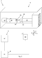
- a machine tool apparatus 2 comprising a machine tool 4, a numerical controller 6 (NC) (for example, a computer numerical controller or "CNC"), a PC 8 and a transmitter/receiver interface 10.
- the machine tool 4 comprises a tool holder 12 which holds and moves a tool 20 relative to a workpiece 16 which is mounted in a spindle 18.
- the NC 6 controls rotation of the spindle 18 and x, y, z movement of the tool holder 12 within the work area of the machine tool using motors and encoders (not shown) or the like.
- the NC 6 can be programmed with a machining operation, for example via the PC 8.
- the tool 20 is a boring bar, and comprises a tool body 22 and a tool insert 24, (such as a cutting insert, which is configured to interact with (e.g. cut) the workpiece so as to process the workpiece.
- the boring bar 20, in particular the tool body 22, comprises at least one sensor 26 for measuring/monitoring one or more aspects/properties of the tool during working of a workpiece.
- the tool body comprises an accelerometer (for measuring/monitoring vibrations), a temperature sensor, and a strain gauge which in the figure are collectively illustrated by box 26. As shown, the sensors 26 are located at the end of the tool body 22 proximal the tool insert 24.
- one or more sensors for measuring/monitoring one or more aspects/properties of the machine tool during working of a workpiece can be provided, e.g. in the tool holder 12 and/or spindle 18 (in addition to, or instead of, the sensor(s) in the tool20.
- the workpiece 16 can be worked on by the tool 20, by moving the tool insert 24 into the workpiece 16 whilst it is being turned by the spindle 18.
- data from the at least one sensor 26 in the tool body 22 can be obtained.
- data relating to at least one of temperature, vibration, load and deflection of the tool can be obtained.
- Such data can be transmitted to an external device, e.g. to the NC 6 and/or PC 8, for example via a wireless link and interface unit 10.
- the at least one sensor 26 could communicate with an interface unit 10 via the Bluetooth wireless technology standard.
- the data is streamed instantaneously and continuously. However, as will be understood, this need not necessarily be the case.
- the data could be transmitted, at intervals (regular or irregular), or only when requested, for example.
- data from the at least one sensor 26 could be stored locally within memory in the tool 20, and downloaded to the NC 6 and/or PC 8 at a later time, e.g. subsequent to working of the tool, e.g. via a wired or wireless link.
- Figure 2 illustrates that a measurement probe 30 can be loaded in the tool holder 12 of the machine tool 4 in place of the tool 20 ( Figure 1 ).
- the probe 30 is a contact probe, comprising a body 32 which is mounted to the tool holder 12, a stylus 34 extending from the body 32 and a stylus tip 36 at the end of the stylus 34 distal the body 32.
- the stylus 34 can deflect relative to the body 32 (e.g. when the stylus tip 36 touches a surface), and such deflections can be detected by sensors in the body 32.
- the probe is a scanning probe (also known in the art as an analogue probe) in that the extent/amount/degree of the deflection of the stylus from a rest position can be sensed and reported by the probe 30 (in contrast to a touch-trigger probe which only reports when the stylus has deflected, e.g. by a predetermined threshold amount).
- a scanning probe also known in the art as an analogue probe
- Such scanning probes for machine tools are known; for instance the SPRINTTM probe available from Renishaw plc.
- other probes and other technologies could be used.
- the part of the workpiece worked on can be measured by bringing the stylus tip 36 into contact with the surface of the workpiece 16.
- Stylus deflection data from the probe 30 can be streamed instantaneously and continuously to the NC 6 and/or PC 8, for example wirelessly, via an interface 10. As per the tool described above, this could be via Bluetooth connection.
- other techniques could be used to transfer stylus deflection data.
- the data could be transmitted at intervals (regular or irregular), or only when requested, for example.
- stylus deflection data could be stored locally within memory in the probe 30, and downloaded to the NC 6 and/or PC 8 at a later time, e.g. via a wired or wireless link.
- data from the probe 30 could be combined with machine tool position data; for example, combined with data concerning the relative position of the probe 30 and workpiece 16.
- data from the probe 30 could be combined with tool holder 12 position data, which could be obtained from encoders (not shown) which monitor the position of the tool holder 12 in any or all of the x, y and z axes.
- the measurement data about the part of the workpiece worked on could be the raw data obtained/output by the probe 30, or could data obtained by processing the raw data obtained/output by the probe 30 (e.g. by combining it with other data, such as data about the position of the tool holder 12).
- measurement probes other than scanning stylus deflection probes can be used.
- a touch-trigger measurement probe or a surface-finish probe could be used.
- a non-contact probe could be used.
- the part does not need to be measured on the same machine.
- the part could be removed from the machine tool and measured on a coordinate measuring machine (CMM) or the like.
- CCM coordinate measuring machine
- the example process 100 begins at step 102 at which the workpiece 16 is worked on by the tool 20, and data from the tool's 20 at least one sensor 26 is obtained during the working of the workpiece.
- the tool sensor data can be stored in memory (e.g. in the PC 8) for subsequent use.
- the data could be stored elsewhere, for example in the NC 6, interface 10, or elsewhere, such as in network storage or in the cloud.
- the part of the workpiece 16 worked on by the tool 20 is then measured using the measurement probe 30 to obtain measurement data (e.g. dimensional and/or surface roughness/waviness data) about the part.
- the measurement data can be stored in memory for subsequent use.
- the tool sensor data and the measurement data obtained at steps 102 and 104 are used to determine sensor-to-workpiece data calibration information.
- a model which models the relationship between i) a particular property of the tool (such as load on the tool, measured by a strain-gauge for example) and ii) the error in a dimension of the part (for example the diameter of a bore), can be determined from one or more test cuts and measurements of the workpiece.
- a model could be in the form of a function or a lookup table, for example.
- Figure 4a is a graph illustrating a model determined from two different test bore-cuts which were performed at two different loads, and from the error in the diameter of the bore formed by those two test cuts. These results are shown plotted on the graph of Figure 4a .
- a model e.g. a function
- This model could be (or form the basis of) a calibration model for the workpiece. Accordingly, for subsequent cuts on the workpiece (or on nominally identical workpieces), the error in the diameter of the bore (and hence the actual dimension of the bore) can be inferred from the load measured during the cutting process.
- test cuts were obtained.
- more or fewer test cuts could be obtained.
- the calibration model could be based on a (straight or curved) line of best-fit through the measurements obtained from the different test cuts.
- the inventors have found that there can be significant benefit of performing one or more test cuts on the (or on a nominally identical) workpiece, measuring the part(s) that was (were) cut, and determining a calibration model/function for that workpiece (and for subsequent workpieces in a series of nominally identical workpieces).
- the sensor-to-workpiece data calibration information can then be workpiece-specific. For instance, this could comprise performing just one test cut, and based thereon, adapting the generic model. For example, as illustrated in Figure 4b , it could be that it is determined that for a measured load of "x" during machining of a bore, the actual error in the diameter of the bore is e 2 , not e 1 as was predicted by the generic model.
- an adapted calibration model could be determined by offsetting the generic model by the difference between e 2 and e 1 .
- more than one test cut and measurement thereof can be performed if desired, which could provide more accurate offset information.
- Figure 4c the same approach could be taken for properties of the other than load.
- a generic model of measured vibration vs surface roughness (Ra) can be adapted based on an actual reading of surface roughness experienced at a particular measured level of vibration "y”.
- the calibration information (e.g. a function, model, data or other appropriate information) can then be stored in memory (e.g. in the PC) for subsequent use.
- the workpiece (or for example, a nominally identical workpiece) is worked on again by the tool (or for example a nominally identical tool), represented by step 108 in the process 100.
- tool sensor data from the tool's 20 at least one sensor 26 is obtained during the working of the workpiece and stored in memory (e.g. in the PC) for subsequent use.
- the calibration information obtained at step 106 and the tool sensor data obtained at step 108 are used to infer measurement data about the part of the workpiece worked on at step 108.
- this can comprise using the model determined at step 106 to look up the inferred error in diameter based on the load applied to the tool as measured by the sensor 26 during the machining process of step 108.
- this can comprise using the model determined at step 106 to determine the surface roughness of the part based on vibration as measured by the sensor 26 during the machining process of step 108.
- this inferred measurement data can then be stored in memory (e.g.
- such use of the inferred measurement data can comprise at least one of determining: whether to accept or reject a workpiece; how to adjust subsequent working of the workpiece either in real-time or during a subsequent processing step; and/or stop the process.
- measurement data about the part of the workpiece worked on can be determined without having to actually directly measure the part with a measurement tool.
- the method can comprise using the calibration information determined at step 106 to determine process control parameters for use in controlling subsequent machining steps (of the same or nominally identical workpieces). For example, the method can comprise determining a threshold vibration level, above which corrective action should be taken.
- references herein to storing data in memory can comprise storing data in a permanent storage and/or transitory memory e.g. (random-access memory "RAM").
- RAM random-access memory
- the above mentioned storing steps can be optional.
- the inferred measurement data could be transmitted to an external device, and/or used immediately (e.g. by the NC 6 to make a decision) without being stored in a storage device.
- interface 10 is shown common to the NC 6 and PC 8, they could each have their own separate interface 10. Furthermore, such an interface could be embedded within the NC 6 and/or PC 8, rather than being separate as depicted in the Figures.
- the measurement probe 30 is mounted in the tool holder 12 in place of the tool 20.
- the measurement probe could be mounted on a separate tool holder, or other part, of the machine tool. In this case, it would not be necessary to swap the tool for the measurement probe.
- the same part, same tool and same machine are used in all steps.
- the workpiece, tool and/or machine tool used at steps 102 and 104 could be different (albeit nominally identical), to the workpiece, tool and/or machine tool used at step 108.
- the calibration information could be obtained on a different machine tool.
- steps 102 and 104 could be performed on a different machine tool to step 108.
- steps 102 and 108 could be performed on the same machine tool, but step 104 could be obtained on a different apparatus, for example a different machine tool or a dedicated measuring apparatus such as a coordinate measuring machine (CMM).
- CCMM coordinate measuring machine
- tools other than boring bars can be used.
- the tool could comprise a drill, grinding wheel, or a milling, reaming or milling tool.
- any or all of the x, y and z dimensions could be provided by movement of the lathe instead of or as well as the tool holder 12. Furthermore, movement might be restricted to fewer dimensions, e.g. only x, and/or y.
- the embodiment described comprises a cartesian machine tool, whereas will be understood this need not necessarily be the case and could be instance be a non-cartesian machine tool.
- the present invention is shown in conjunction with a lathe machine tool, the invention could be used with many other types of machine tool apparatus and machining centres, such as milling machine tool apparatus (e.g. in which the tool is held in a spindle which can be moved). Accordingly, the invention could be used with embodiments in which the tool is rotating and the part is held stationary.
- steps 102 and 104 could be repeated, for example on different (e.g. nominally identical) workpieces, from which the calibration information is obtained at step 106.
- the method comprises performing an initial test cut and measurement to determine the calibration information before subsequent machining takes place. Nevertheless, as will be understood, this need not necessarily be the case, and machining operations for which information is inferred could have taken place before the calibration information is determined.
- the method can comprise performing multiple machining operations on one workpiece (or on a plurality of nominally workpieces), measuring just one (or just some of the) part(s) which has (have) been machined (or measuring just one or some of the workpieces for example) to determine the calibration information therefrom, and then using the calibration information to infer information about the other parts of the workpiece (or about the other workpieces) which have already been machined.
Landscapes
- Physics & Mathematics (AREA)
- General Physics & Mathematics (AREA)
- Engineering & Computer Science (AREA)
- Mechanical Engineering (AREA)
- Human Computer Interaction (AREA)
- Manufacturing & Machinery (AREA)
- Automation & Control Theory (AREA)
- Machine Tool Sensing Apparatuses (AREA)
- Cutting Tools, Boring Holders, And Turrets (AREA)
- Testing Of Devices, Machine Parts, Or Other Structures Thereof (AREA)
- Numerical Control (AREA)
Priority Applications (6)
| Application Number | Priority Date | Filing Date | Title |
|---|---|---|---|
| EP19165429.2A EP3715977A1 (de) | 2019-03-27 | 2019-03-27 | Kalibrierverfahren und verfahren zur gewinnung von werkstückinformationen |
| US17/441,071 US11794299B2 (en) | 2019-03-27 | 2020-03-11 | Calibration method and method of obtaining workpiece information |
| JP2021557535A JP7649751B2 (ja) | 2019-03-27 | 2020-03-11 | 較正方法およびワークピース情報の取得方法 |
| CN202080031827.2A CN113785250B (zh) | 2019-03-27 | 2020-03-11 | 校准方法以及获得工件信息的方法 |
| PCT/GB2020/050583 WO2020193944A1 (en) | 2019-03-27 | 2020-03-11 | Calibration method and method of obtaining workpiece information |
| EP20711304.4A EP3948453B1 (de) | 2019-03-27 | 2020-03-11 | Kalibrierverfahren und verfahren zur gewinnung von werkstückinformationen |
Applications Claiming Priority (1)
| Application Number | Priority Date | Filing Date | Title |
|---|---|---|---|
| EP19165429.2A EP3715977A1 (de) | 2019-03-27 | 2019-03-27 | Kalibrierverfahren und verfahren zur gewinnung von werkstückinformationen |
Publications (1)
| Publication Number | Publication Date |
|---|---|
| EP3715977A1 true EP3715977A1 (de) | 2020-09-30 |
Family
ID=66182342
Family Applications (2)
| Application Number | Title | Priority Date | Filing Date |
|---|---|---|---|
| EP19165429.2A Ceased EP3715977A1 (de) | 2019-03-27 | 2019-03-27 | Kalibrierverfahren und verfahren zur gewinnung von werkstückinformationen |
| EP20711304.4A Active EP3948453B1 (de) | 2019-03-27 | 2020-03-11 | Kalibrierverfahren und verfahren zur gewinnung von werkstückinformationen |
Family Applications After (1)
| Application Number | Title | Priority Date | Filing Date |
|---|---|---|---|
| EP20711304.4A Active EP3948453B1 (de) | 2019-03-27 | 2020-03-11 | Kalibrierverfahren und verfahren zur gewinnung von werkstückinformationen |
Country Status (5)
| Country | Link |
|---|---|
| US (1) | US11794299B2 (de) |
| EP (2) | EP3715977A1 (de) |
| JP (1) | JP7649751B2 (de) |
| CN (1) | CN113785250B (de) |
| WO (1) | WO2020193944A1 (de) |
Families Citing this family (9)
| Publication number | Priority date | Publication date | Assignee | Title |
|---|---|---|---|---|
| JP6973689B1 (ja) * | 2020-04-13 | 2021-12-01 | 住友電気工業株式会社 | 切削システム、表示システム、処理装置、処理方法および処理プログラム |
| JP7519966B2 (ja) * | 2021-08-23 | 2024-07-22 | オークマ株式会社 | 工作機械における接触式工具センサの校正方法及び校正プログラム、工作機械 |
| TWI791361B (zh) * | 2021-12-24 | 2023-02-01 | 財團法人工業技術研究院 | 用於工具機的校正方法及校正系統 |
| US11921487B2 (en) | 2022-02-18 | 2024-03-05 | Pratt & Whitney Canada Corp. | System and method for machining a component |
| CN114543719B (zh) * | 2022-03-04 | 2025-05-27 | 佛山准测电子有限公司 | 检测方法及多功能检测装置 |
| CN114839924B (zh) * | 2022-04-15 | 2025-10-14 | 南通国盛智能科技集团股份有限公司 | 刀具数据监视方法及相关装置、电子设备和存储介质 |
| EP4300223A1 (de) * | 2022-06-30 | 2024-01-03 | AB Sandvik Coromant | Verfahren und system zur bestimmung der position eines punktes auf einer oberfläche |
| CN116627090B (zh) * | 2023-07-19 | 2023-11-10 | 太仓庄正数控设备有限公司 | 基于切削状态诊断的数控机床调控方法及系统 |
| CN120002028A (zh) * | 2025-02-27 | 2025-05-16 | 上海外高桥造船有限公司 | 船舶艉轴管镗孔作业的镗刀机构 |
Citations (2)
| Publication number | Priority date | Publication date | Assignee | Title |
|---|---|---|---|---|
| US20080105094A1 (en) * | 2004-12-20 | 2008-05-08 | Renishaw Plc | Machine and Control System |
| US20130116817A1 (en) * | 2011-11-04 | 2013-05-09 | United Technologies Corporation | System and method for machining and inspecting a workpiece |
Family Cites Families (24)
| Publication number | Priority date | Publication date | Assignee | Title |
|---|---|---|---|---|
| CN1207183A (zh) * | 1996-10-09 | 1999-02-03 | 卡劳斯-马菲股份公司 | 用于工件切削加工的机床 |
| DE19715634C1 (de) | 1997-04-15 | 1998-11-19 | Klaus Dr Ing Nordmann | Verfahren zur Werkstückmaßkontrolle und Erhöhung der Bearbeitungsgenauigkeit spanender Werkzeugmaschinen |
| JP2001353643A (ja) | 2000-06-16 | 2001-12-25 | Hitachi Ltd | 精密工作機械 |
| GB0205332D0 (en) | 2002-03-06 | 2002-04-17 | Renishaw Plc | Dynamic artefact comparison |
| DE10312884B4 (de) * | 2003-03-22 | 2014-02-27 | Dr. Johannes Heidenhain Gmbh | Tastsystem |
| JP2006107073A (ja) | 2004-10-05 | 2006-04-20 | Nagano Prefecture | 加工情報共有システムおよびその方法 |
| GB0518078D0 (en) * | 2005-09-06 | 2005-10-12 | Renishaw Plc | Signal transmission system |
| DE102008006927A1 (de) * | 2008-01-24 | 2009-07-30 | Afm Technology Gmbh | Anordnung zur Korrektur einer Positionssensoreinheit und korrespondierendes Positionierungssystem und Verfahren zur Korrektur eines Positionierungssystem |
| JP2011518048A (ja) | 2008-03-17 | 2011-06-23 | エイ. サプロック,クリストファー | スマートマシニングシステム及びそれに用いられるスマートツールホルダー |
| JP5351639B2 (ja) * | 2009-07-17 | 2013-11-27 | 国立大学法人京都大学 | 機上測定方法及び測定装置 |
| ES2769304T3 (es) * | 2012-04-05 | 2020-06-25 | Fidia Spa | Dispositivo para corrección de errores para máquinas CNC |
| CN103273376B (zh) * | 2013-06-19 | 2015-06-24 | 四川普什宁江机床有限公司 | 基于数控滚齿机床的自动二次对刀方法 |
| DE102014214771A1 (de) * | 2014-07-28 | 2016-01-28 | Carl Zeiss Industrielle Messtechnik Gmbh | Verfahren zur Erstellung eines Messprotokolls und Rechner zur Ausführung eines solchen Verfahrens |
| JP6426667B2 (ja) | 2016-08-10 | 2018-11-21 | 三菱重工工作機械株式会社 | 工作機械の工具の異常検知装置及び方法 |
| JP6921511B2 (ja) | 2016-12-02 | 2021-08-18 | 株式会社東京精密 | 自動工具交換装置付き工作機械及び自動測定方法 |
| WO2019053837A1 (ja) | 2017-09-14 | 2019-03-21 | 株式会社日立製作所 | 工作機械の監視システム |
| JP6599956B2 (ja) * | 2017-10-23 | 2019-10-30 | ファナック株式会社 | 工作機械の加工条件選定装置 |
| CN108581637A (zh) * | 2018-04-27 | 2018-09-28 | 华中科技大学 | 一种激光位移传感器在机测量系统 |
| EP3686548B1 (de) | 2019-01-22 | 2021-10-27 | AB Sandvik Coromant | Verfahren und anordnung zur messung des durchmessers eines werkstücks |
| JP7249846B2 (ja) * | 2019-03-28 | 2023-03-31 | ヘキサゴン・メトロジー株式会社 | Cnc加工装置のキャリブレーション方法 |
| US11768574B2 (en) * | 2019-05-07 | 2023-09-26 | Hexagon Metrology, Inc. | Graphical user interface for scheduling and monitoring an automated inspection process for batch production |
| US11745305B2 (en) * | 2019-07-05 | 2023-09-05 | Moore Nanotechnology Systems, LLC | System and method for correcting machining error during a precision jig grinding process |
| IT202000007432A1 (it) * | 2020-04-07 | 2021-10-07 | Proquadro S R L | “Macchina utensile a controllo numerico” |
| US20230008247A1 (en) * | 2021-07-06 | 2023-01-12 | Ricoh Company, Ltd. | Diagnostic system, diagnostic method, and recording medium |
-
2019
- 2019-03-27 EP EP19165429.2A patent/EP3715977A1/de not_active Ceased
-
2020
- 2020-03-11 JP JP2021557535A patent/JP7649751B2/ja active Active
- 2020-03-11 WO PCT/GB2020/050583 patent/WO2020193944A1/en not_active Ceased
- 2020-03-11 US US17/441,071 patent/US11794299B2/en active Active
- 2020-03-11 CN CN202080031827.2A patent/CN113785250B/zh active Active
- 2020-03-11 EP EP20711304.4A patent/EP3948453B1/de active Active
Patent Citations (2)
| Publication number | Priority date | Publication date | Assignee | Title |
|---|---|---|---|---|
| US20080105094A1 (en) * | 2004-12-20 | 2008-05-08 | Renishaw Plc | Machine and Control System |
| US20130116817A1 (en) * | 2011-11-04 | 2013-05-09 | United Technologies Corporation | System and method for machining and inspecting a workpiece |
Also Published As
| Publication number | Publication date |
|---|---|
| JP2022528842A (ja) | 2022-06-16 |
| CN113785250A (zh) | 2021-12-10 |
| EP3948453B1 (de) | 2026-04-29 |
| EP3948453A1 (de) | 2022-02-09 |
| CN113785250B (zh) | 2025-09-23 |
| WO2020193944A1 (en) | 2020-10-01 |
| US11794299B2 (en) | 2023-10-24 |
| JP7649751B2 (ja) | 2025-03-21 |
| US20220184765A1 (en) | 2022-06-16 |
Similar Documents
| Publication | Publication Date | Title |
|---|---|---|
| US11794299B2 (en) | Calibration method and method of obtaining workpiece information | |
| CN115398360B (zh) | 用于机床上的基于特征图的误差补偿的机床控制和方法 | |
| EP2839240B1 (de) | Verfahren zur analogmessungsabtastung auf einem maschinenwerkzeug und entsprechendes maschinenwerkzeug | |
| EP3130971A1 (de) | Maschinenwerkzeugbahnkompensierung mit vibrationserfassung | |
| CN109085797B (zh) | 生成计算机数字控制机床偏移而不受周期时间影响的方法 | |
| CN109623485A (zh) | 一种数控机床刀具长度补偿系统及方法 | |
| EP3280974B1 (de) | Sondendatenanalyse zur identifizierung einer eigenschaft des abtastpfads | |
| US11435180B2 (en) | Method and apparatus for measurement cycle generation | |
| Guiassa et al. | Calibration of the cutting process and compensation of the compliance error by using on-machine probing | |
| US10955238B1 (en) | In-process automatic recalibration | |
| CN202656009U (zh) | 面向数控车床的零件加工精度在线检测系统 | |
| CN120295222A (zh) | 一种多轴联动数控机床控制系统 | |
| Li | Real-time prediction of workpiece errors for a CNC turning centre, Part 1. Measurement and identification | |
| US20250389527A1 (en) | Method and system for determining a position of a point on a surface | |
| US20090211338A1 (en) | Measuring Apparatus and Associated Method | |
| KR20120103993A (ko) | 세팅된 공구의 안전영역 판단 방법 및 판단 장치 | |
| Jankowski et al. | Testing of the delay time of wireless communication of CNC machine tools’ probes and controller | |
| Roth et al. | Quality and Inspection of Machining Operations: Review of Condition Monitoring and CMM Inspection Techniques—2000 to Present | |
| CN121132382A (zh) | 一种用于精镗孔位置度控制的补偿方法和装置 | |
| Czerech et al. | Influence of CNC machine tool technical condition on the geometrical accuracy of freeform surfaces | |
| Tseng et al. | Modeling and Analysis between In-Process CNC Touch Probe Gauging and Post-Process CMM Inspection |
Legal Events
| Date | Code | Title | Description |
|---|---|---|---|
| PUAI | Public reference made under article 153(3) epc to a published international application that has entered the european phase |
Free format text: ORIGINAL CODE: 0009012 |
|
| STAA | Information on the status of an ep patent application or granted ep patent |
Free format text: STATUS: THE APPLICATION HAS BEEN PUBLISHED |
|
| AK | Designated contracting states |
Kind code of ref document: A1 Designated state(s): AL AT BE BG CH CY CZ DE DK EE ES FI FR GB GR HR HU IE IS IT LI LT LU LV MC MK MT NL NO PL PT RO RS SE SI SK SM TR |
|
| AX | Request for extension of the european patent |
Extension state: BA ME |
|
| STAA | Information on the status of an ep patent application or granted ep patent |
Free format text: STATUS: THE APPLICATION HAS BEEN REFUSED |
|
| 18R | Application refused |
Effective date: 20201017 |