EP3716405B1 - Linear-zu-cp-polarisator mit verbesserter leistung in victs-antennen - Google Patents
Linear-zu-cp-polarisator mit verbesserter leistung in victs-antennen Download PDFInfo
- Publication number
- EP3716405B1 EP3716405B1 EP20162667.8A EP20162667A EP3716405B1 EP 3716405 B1 EP3716405 B1 EP 3716405B1 EP 20162667 A EP20162667 A EP 20162667A EP 3716405 B1 EP3716405 B1 EP 3716405B1
- Authority
- EP
- European Patent Office
- Prior art keywords
- polarizer
- meanderline
- gridline
- antenna
- antenna system
- Prior art date
- Legal status (The legal status is an assumption and is not a legal conclusion. Google has not performed a legal analysis and makes no representation as to the accuracy of the status listed.)
- Active
Links
Images


Classifications
-
- H—ELECTRICITY
- H01—ELECTRIC ELEMENTS
- H01Q—ANTENNAS, i.e. RADIO AERIALS
- H01Q15/00—Devices for reflection, refraction, diffraction or polarisation of waves radiated from an antenna, e.g. quasi-optical devices
- H01Q15/24—Polarising devices; Polarisation filters
- H01Q15/242—Polarisation converters
- H01Q15/244—Polarisation converters converting a linear polarised wave into a circular polarised wave
-
- H—ELECTRICITY
- H01—ELECTRIC ELEMENTS
- H01Q—ANTENNAS, i.e. RADIO AERIALS
- H01Q13/00—Waveguide horns or mouths; Slot antennas; Leaky-waveguide antennas; Equivalent structures causing radiation along the transmission path of a guided wave
- H01Q13/20—Non-resonant leaky-waveguide or transmission-line antennas; Equivalent structures causing radiation along the transmission path of a guided wave
- H01Q13/28—Non-resonant leaky-waveguide or transmission-line antennas; Equivalent structures causing radiation along the transmission path of a guided wave comprising elements constituting electric discontinuities and spaced in direction of wave propagation, e.g. dielectric elements or conductive elements forming artificial dielectric
-
- H—ELECTRICITY
- H01—ELECTRIC ELEMENTS
- H01Q—ANTENNAS, i.e. RADIO AERIALS
- H01Q15/00—Devices for reflection, refraction, diffraction or polarisation of waves radiated from an antenna, e.g. quasi-optical devices
- H01Q15/24—Polarising devices; Polarisation filters
- H01Q15/242—Polarisation converters
- H01Q15/246—Polarisation converters rotating the plane of polarisation of a linear polarised wave
-
- H—ELECTRICITY
- H01—ELECTRIC ELEMENTS
- H01Q—ANTENNAS, i.e. RADIO AERIALS
- H01Q21/00—Antenna arrays or systems
- H01Q21/0006—Particular feeding systems
Definitions
- the present invention relates to an antenna system comprising a linear-to-circular radio frequency (RF) polarizer.
- RF radio frequency
- one method of achieving circular polarization includes using dual-linear polarized array elements combined with 90-degree hybrid networks incorporated within the antenna feed.
- Such hybrid networks provide the necessary power split and phase shift between radiated linearly-polarized field components to achieve circular polarization.
- this technique can degrade axial ratio (polarization purity) performance at frequency and scan angle extremes due to element cross-polarization contamination and reduced network performance at band edges.
- Another method for achieving circular polarization for traditional phased arrays is through the use of a multi-layer meanderline polarizer.
- a multi-layer meanderline polarizer offers a proven viable alternative approach that does not require expensive dual polarized array elements or hybrid feed networks.
- the polarizer which is typically fabricated using low loss, low cost printed circuit board techniques, is permanently affixed to the radiating array aperture. As linear polarized waves emanating from the array travel through the polarizer the electric field resolves into two orthogonal components, one parallel to the meanderline axis and one perpendicular to the meanderline axis.
- the component parallel to the meanderline axis experiences an inductive shunt load leading to a positive transmitted phase shift, while the component perpendicular to the meanderline axis experiences a shunt capacitive load leading to a negative transmitted phase shift.
- the combined radiated electric field is elliptically polarized achieving either right-hand elliptical polarization or left-hand elliptical polarization depending on the rotation angle of the meanderline axis.
- the radiating polarization is more commonly described in industry as being 'circularly polarized' (either right-hand circular polarization (RHCP) or left-hand circular polarization (LHCP)) with an axial ratio greater than 1.
- An antenna system according to the preamble of claim 1 is known from CN 108 155 483 A .
- GEO geostationary equatorial orbit
- MEO medium earth orbit
- LEO low earth orbit
- a problem of limited scan volume of conventional antenna systems is addressed with a novel approach described herein where a scanning antenna, such as a Variable Inclination Continuous Transverse Stub (VICTS) antenna, is combined with a novel polarizer in accordance with the present invention.
- VIP Variable Inclination Continuous Transverse Stub
- Such combination produces diverse polarization performance over a near-hemispherical scan volume that can meet current cross-polarization isolation requirements.
- performance over large scan angles is superior to conventional devices, including improvement in both transmit efficiency and polarization purity.
- an antenna system as defined in claim 1 is provided.
- the dependent claims define preferred and/or advantageous embodiments of the invention.
- VCTS Variable Inclination Continuous Transverse Stub
- aspects of the invention are also applicable to other scanning planar antenna systems, including but not limited to electronically-scanned slotted planar arrays, printed patch arrays, open-ended waveguide arrays, or the like.
- a VICTS antenna in its simplest form includes two components, namely an aperture and a feed.
- Antenna main beam scanning in ⁇ is achieved via rotation of the aperture with respect to the feed. This type of rotation also scans the antenna main beam over a small range of ⁇ (azimuth), while additional desired scanning in ⁇ is achieved by rotating the aperture and feed simultaneously, leading to near hemispherical scan coverage.
- a multi-layer meanderline polarizer having a plurality of meanderline conductor patterns is combined with a gridline polarizer having a plurality of conductors arranged in a grid pattern to provide optimum axial ratio over frequency and scan.
- a gridline polarizer is used solely for linearly-polarized applications, whereas a meanderline polarizer is used solely for circularly-polarized applications.
- the former generally does not require the latter (no CP performance required, by definition) and the latter generally does not require the former (as the incoming RF plane-wave incident on the meanderline polarizer is (by definition) already linear).
- the novel combination of the two is applicable when the meanderline polarizer is conformally placed very close to (less than 1 ⁇ 4 wavelength) from a complex planar array surface.
- the novel addition of the gridline polarizer allows for favorable suppression of non-radiating high-order "evanescent" modes which would otherwise couple (due to the very close proximity of the polarizer) and (1) degrade the cross-polarization isolation characteristics of the outgoing wave and (2) result in RF losses and pattern degradation associated with coupled surface waves, in the antenna/meanderline polarizer ensemble.
- the novel addition of the gridline polarizer significantly improves the cross-polarization isolation of the ensemble, particularly at larger scan angles where undesired coupling to higher-order modes associated with the scanning would otherwise degrade overall performance of if the grid polarizer were not present, as compared to "standard" meanderline polarizer embodiments.
- the multi-layer meanderline polarizer's and the gridline polarizer's conductor dimensions, internal dielectric substrate separation and thickness, and their respective rotation angles as well as the meanderline to gridline polarizer spacing and the gridline polarizer to VICTS aperture spacing are designed to work with the VICTS antenna to provide electric field component magnitude and phasing that achieves optimum axial ratio performance and impedance match over frequency and scan angle.
- both the meanderline rotation angle and the gridline rotation angle for achieving optimum axial ratio versus scan angle are synchronized with the antenna main beam position ⁇ angle-profile versus VICTS scan angle, ⁇ .
- a multi-layer meanderline polarizer is a device that, when added to the radiating face of an aperture antenna, achieves various polarization states by converting the (usually linear) polarization emanating from the aperture to another polarization state (usually either elliptical or linear polarization).
- a meanderline polarizer is generically defined as a passive RF structure that includes two or more thin dielectric substrate layers, upon each of which is printed/etched a one-dimensional array of parallel conductive "meandering" ("square-wave-like") trace/patterns such that each layer exhibits anisotropic (polarization-orientation-dependent) properties.
- the RF insertion phase (phase difference between incident and transmitted waves) for incident plane waves with linear polarization aligned parallel to the axis of the meanderline favorably differ from the RF insertion phase for incident plane waves aligned orthogonal to the meanderline axes.
- phase differential multiple layers are employed to achieve the desired net differential phase (typically 90 degrees for linear-to-circular polarizer applications.)
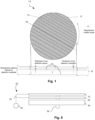
- an exemplary multi-layer meanderline polarizer 10 is shown that includes one or more dielectric substrates (layers) 12 each possessing a plurality of periodic meanderline conductor patterns 14 laterally spaced apart from one another. While the conductor pattern 14 of the meanderline polarizer 10 is illustrated as a square wave pattern, other patterns are possible. For example, the meanderline conductor pattern 14 may be sinusoidal or curvilinear.
- the conductor patterns 14 can be fabricated using various techniques, such as etching them on the dielectric substrates 12 using printed circuit board manufacturing processes.
- the substrates 12 can be formed from conventional materials, such as plastic materials or the like.
- Dielectric spacers 16, such as low density foam, air or the like, are arranged between adjacent substrates 12 and can maintain the spacing between adjacent substrates 12.
- Low density dielectric foam is generally recognized as an engineered foam comprised of a common dielectric material (polyethylene, polystyrene, polypropylene, etc. generally with dielectric constants between 2 and 3.5) and air with an effective dielectric constant of 1.4 or lower (air is 1.0).
- the dimensions of the meanderline conductor pattern 14 along with the thicknesses of the dielectric substrates 12 and spacers 16 can be adjusted to achieve optimum impedance match and polarization purity.
- a meanderline axis 18, which is an imaginary line drawn parallel to the conductor pattern 14, is shown in Fig. 1 .
- a grid-type, or "gridline”, polarizer is a device that when added to the radiating face of an aperture antenna achieves various polarization states by converting the (usually linear) polarization emanating from the aperture to another polarization state (usually rotated linear polarization).
- a gridline polarizer is generically defined as a passive RF structure that includes one or more thin dielectric substrate layers, upon each of which is printed/etched a closely spaced (e.g., 1/4 wavelength or less) one-dimensional array of parallel conductive lines such that the/each layer exhibits anisotropic (polarization-orientation-dependent) properties. Incident waves with linear polarization aligned parallel to the conductive lines are highly (95% or more) reflected (i.e. 5% or less transmitted) whereas incident waves with linear polarization aligned orthogonal to the conductive lines are largely (95% or more) transmitted (i.e. 5% or less reflected.)
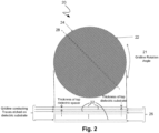
- an exemplary grid-type polarizer 20 that includes one or more dielectric substrates (layers) 22 each possessing a periodically spaced pattern of parallel conducting traces 24 of finite width separated by dielectric spacers 26 (e.g., low density foam, air, etc.).
- the substrates 22 also can be formed using conventional materials, such as plastic materials or the like.
- the conducting traces 24, which preferably are parallel to one another, can be fabricated using various techniques such as etching metal-clad dielectric substrates using printed circuit board manufacturing processes. The dimensions of and spacing between the conducting traces 24 along with the thicknesses of the dielectric substrates 22 and spacers 26 can be adjusted to achieve optimum impedance match and polarization purity.
- the spacing between adjacent gridlines of the gridline polarizer is equal throughout the grid pattern. In another embodiment, the spacing is unequal, e.g., at least two different spacings are used for different groups of traces. In yet another embodiment, the gridline spacing on each substrate is different (e.g., substrate "A” has a spacing between adjacent gridlines of "x", while substrate “B” has a spacing between adjacent gridlines of "y", where y is not equal to x).
- a gridline axis 28, which is an imaginary line drawn parallel to the conducting traces 24, is shown in Fig. 2 .
- Figs. 3 and 4 illustrated is an exploded view ( Fig. 3 ) and a side view ( Fig. 4 ) of a combination of the meanderline polarizer 10, the gridline polarizer 20, and a VICTS antenna 30 in accordance with the present invention.
- the meanderline polarizer 10, gridline polarizer 20 and VICTS antenna 30 each have a circular form factor. While other form factors are possible, due to the relative-rotation capability of the polarizers with respect to each other and to the VICTS antenna 30, a circular form factor is best suited for minimizing the overall size of the system while at the same time providing optimal performance.
- the meanderline polarizer 10 and the gridline polarizer 20 are concentric with one another.
- the VICTS antenna 30 also may be concentric with the meanderline and gridline polarizers.
- the VICTS antenna 30 includes an antenna port 32 for receiving/outputting an RF signal, and lower and upper conducting plates 34 and 36 as is conventional.
- the upper conducting plate 36 includes a plurality of stubs 38 that define an aperture 39 of the VICTS antenna 30.
- the combination of the meanderline polarizer 10, gridline polarizer 20 and VICTS antenna 30 forms a unique antenna device 40 that provides multiple polarization states over a near hemispherical scan volume.
- the gridline polarizer 20 serves to pre-adjust the rotation angle of the direction of the polarization vector emanating from the VICTS antenna 30 while the meanderline polarizer 10 transforms this pre-adjusted linearly polarized wave emanating from the gridline polarizer into an elliptically polarized wave.
- optimized left hand circular polarization (LHCP) or right-hand circular polarization (RHCP) can be achieved with axial ratios near 1 by adjusting the meanderline polarizer rotation angles 11 and gridline polarizer rotation angle 21.
- a pure linear polarization state can also be achieved by adjusting the meanderline and gridline polarizer rotation angles. Since VICTS antennas inherently operate over near-hemispherical scan volumes, the combination of all three devices also provides optimum polarization performance over a near-hemispherical scan volume.
- Figs. 3 and 4 is merely exemplary, and other embodiments are envisioned.
- embodiments with different meanderline polarizer geometries, gridline geometries, and VICTS geometries are possible and may be used in place of those shown in Figs. 3 and 4 .
- the VICTS-based polarizer includes that polarization is achieved in a low part count and in a very low-profile package (0.25 to 0.5 wavelength). Further, the combined meanderline-gridline polarizer can be fabricated using very low loss tangent materials combined with very high conductivity metals, which imparts very low dielectric and ohmic losses to transmitted waves.
- the VICTS-based polarizer may be designed for superior axial ratio performance ( ⁇ 1.25) with corresponding high cross-pol isolation ( > 18 dB) over a large scan volume by adjusting the rotation angles of the meanderline 10 and gridline polarizers 20. Additionally, the VICTS-based polarizer enables switching between two opposite senses of circular polarization (LHCP and RHCP) with identical performance. This is due at least in part to the symmetry of the combined VICTS-polarizer geometry.
- a motive device 50 is operatively coupled to the meanderline polarizer 10 and/or the gridline polarizer 20.
- the motive device 50 may include, for example, a motor 52 (e.g., an electric motor) or other like device, and a drive coupler 54, such as a belt drive, a gear drive, a screw drive, spindle drive, etc. that couples the motor 52 to the polarizers 10, 20.
- the polarizers 10, 20 are mounted to a spindle 56 that enables relative rotation between the respective polarizers about a common axis (e.g., they are axially rotatable about the spindle). In addition to or in lieu of a spindle, such rotation can also be achieved through the use of a bearing supporting the perimeter of each device.
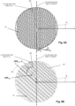
- Fig. 6A illustrates a top view of an exemplary polarizer in accordance with the invention in a spherical coordinate system without the meanderline polarizer so that details of the gridline polarizer 30 and the VICTS aperture 29 (indicated with dashed lines) can be seen.
- Fig. 6B also shows a top view of the meanderline polarizer 10 and the gridline polarizer 20 (only) where the VICTS aperture and feed have been intentionally suppressed for clarity.
- Figs. 6A and 6B each illustrate the ⁇ -beam position locus 60 for a typical VICTS antenna with the aperture fixed with respect to and embedded in a spherical coordinate system.
- Figs. 6A illustrates a top view of an exemplary polarizer in accordance with the invention in a spherical coordinate system without the meanderline polarizer so that details of the gridline polarizer 30 and the VICTS aperture 29 (indicated with dashed lines) can be seen.
- rotation of the gridline polarizer 20 is relative to the stubs of the VICTS antenna 30 (the stubs being parallel to the y-axis), with the aperture 39 fixed with respect to and embedded in a spherical coordinate system.
- Antenna main beam scanning is achieved in this case by rotating the VICTS feed 32 counter-clockwise.
- the ⁇ angle position of the main beam follows the path of the position locus 60.
- the meanderline rotation angle 62 is fixed with respect to the aperture at ⁇ MLopt degrees.
- the gridline rotation angle 64 is fixed with respect to the aperture at ⁇ GLopt degrees as shown in Fig. 6A .
- the difference between the optimum meanderline axis rotation angle and the ⁇ -path of the main beam, ⁇ MLopt - ⁇ varies and is synchronized with the difference needed to achieve optimum axial ratio versus scan.
- the difference between the optimum gridline axis rotation angle and the ⁇ -path of the main beam, ⁇ GLopt - ⁇ varies and is synchronized with the difference needed to achieve optimum axial ratio.
- the meanderline polarizer 10 and the gridline polarizer 20 may be affixed to the top of the aperture without further modification.
- this novel combination of VICTS antenna 30, gridline polarizer 20, and meanderline polarizer 10 achieves excellent axial ratio (and corresponding cross-polarization) characteristics in a low profile, low part-count package over nearly a hemisphere of scan volume.
- Additional improvements to axial ratio may be achieved by fabricating the meanderline polarizer 10 as a separate entity that is not affixed to the aperture 29 of the VICTS antenna 30. This allows the meanderline polarizer 10 to rotate above and with respect to the gridline polarizer 20, aperture 29 of the VICTS antenna 30, and feed 32.
- the meanderline axis rotation angle 62 for achieving optimum axial ratio can be synchronized with each individual scan angle in both ⁇ and ⁇ to achieve better axial ratio than that achieved when the meanderline polarizer 10 is affixed to the aperture of the VICTS antenna 30 and gridline polarizer 20.
- both the meanderline polarizer 10 and gridline polarizer 20 may be fabricating both the meanderline polarizer 10 and gridline polarizer 20 as separate entities (not affixed to the aperture of the VICTS antenna 30) and allowing both to rotate above and with respect to the aperture and feed of the VICTS antenna.
- both the meanderline rotation angle 62 and the gridline rotation angle 64 for achieving optimum axial ratio can be synchronized with each individual scan angle in both ⁇ and ⁇ to achieve better axial ratio than that achieved when both the meanderline polarizer 10 and the gridline polarizer 20 are affixed to the aperture of the VICTS antenna 30.
- the combination of VICTS antenna and polarizers may alternatively be deployed to provide linear polarization.
- Linear polarization is achieved by rotating the meanderline axis 18 and the gridline axis 28 to be parallel to the VICTS radiating element axis (parallel to the axis of the slots/stubs).
- This approach takes advantage of the nearly pure linear polarization characteristic of VICTS antennas.
- This implementation offers an embodiment with the selectable polarization characteristics that can meet the needs of multiple satellite constellations i.e. GEO/MEO/LEO.
- GEO/MEO/LEO satellite constellations
Landscapes
- Variable-Direction Aerials And Aerial Arrays (AREA)
- Polarising Elements (AREA)
Claims (12)
- Antennensystem umfassend:eine planare Antenne (30) mit einer planaren Antennenapertur (29); undeinen linear-zirkularen HF-Polarisator, der einen drehbaren Mäanderlinien-Polarisator (10), der eine Vielzahl von Mäanderlinien-Leitermustern (14) aufweist, und einen drehbaren Gitterlinien-Polarisator (20), der eine Vielzahl von Leitern (24) aufweist, die in einem Gittermuster angeordnet sind, aufweist, wobei der Gitterlinien-Polarisator (20) von dem Mäanderlinien-Polarisator (10) um einen ersten vorgeschriebenen Abstand beabstandet ist und der Gitterlinien-Polarisator (20) von der planaren Antennenapertur (29) der planaren Antenne (30) um einen zweiten vorgeschriebenen Abstand beabstandet ist,wobei die planare Antenne (30) eine VICTS-Abtastantenne bzw. kontinuierliche Abtastantenne mit variabler Neigung in Querrichtung aufweist, die eine Einspeisung (30) aufweist, und wobei die Abtastantenne relativ zu dem Mäanderlinien-Polarisator (10) angeordnet ist, um HF-Signale zwischen der planaren Antennen-Apertur (29) und dem Mäanderlinien-Polarisator (10) zu übertragen,wobei eine Φ-Abtastung eines Hauptstrahls durch Rotation der planaren Antennenapertur (29) in Bezug auf die Einspeisung (30) erreicht wird, und wobei die Φ-Abtastung des Hauptstrahls durch gleichzeitige Rotation der Einspeisung (30), der planaren Antennenapertur (29), des Gitterlinien-Polarisators (20) und des Mäanderlinien-Polarisators (10) erreicht wird,dadurch gekennzeichnet,dass der Mäanderlinien-Polarisator (10) ausgestaltet ist, um eine Differenz zwischen einem optimalen Mäanderlinien-Achsendrehwinkel (ΦMLopt) und einem Φ-Pfad des Hauptstrahls (Φ) bereitzustellen, die mit einem Antennenabtastwinkel variiert; unddass der Gitterlinien-Polarisator (20) ausgestaltet ist, um eine Differenz zwischen einem optimalen Gitterlinien-Achsendrehwinkel (ΦGLopt) und dem Φ-Pfad (Φ) des Hauptstrahls bereitzustellen, die mit dem Antennenabtastwinkel variiert,wobei der Mäanderlinien-Polarisator (10) ausgestaltet ist, um eine Differenz zwischen dem optimalen Mäanderlinien-Achsendrehwinkel (ΦMLopt) und dem Φ-Pfad (Φ) des Hauptstrahls mit einer Differenz zu synchronisieren, die ein optimales Achsenverhältnis gegenüber dem Antennenabtastwinkel erzeugt, und wobei der Gitterlinien-Polarisator (20) ausgestaltet ist, um die Differenz zwischen dem optimalen Gitterlinien-Achsendrehwinkel (ΦGLopt) und dem Φ-Pfad (Φ) des Hauptstrahls mit einer Differenz zu synchronisieren, die ein optimales Achsenverhältnis gegenüber dem Antennenabtastwinkel erzeugt.
- Antennensystem nach Anspruch 1, wobei der Mäanderlinien-Polarisator (10) und der Gitterlinien-Polarisator (20) konzentrisch zueinander angeordnet sind.
- Antennensystem nach Anspruch 1 oder Anspruch 2, wobei der Mäanderlinien-Polarisator (10) und der Gitterlinien-Polarisator (20) relativ zueinander um eine gemeinsame Achse drehbar sind.
- Antennensystem nach einem der Ansprüche 1-3, wobei der Mäanderlinien-Polarisator (10) und der Gitterlinien-Polarisator (20) einen kreisförmigen Formfaktor umfassen.
- Antennensystem nach einem der Ansprüche 1-4, das darüber hinaus eine Antriebseinrichtung (50) umfasst, die betriebsmäßig mit dem Mäanderlinien-Polarisator (10) und/oder dem Gitterlinien-Polarisator (20) gekoppelt ist, wobei die Antriebseinrichtung (50) dazu dient, eine relative Drehung zwischen dem Gitterlinien-Polarisator (20) und dem Mäanderlinien-Polarisator (10) um eine gemeinsame Achse zu bewirken.
- Antennensystem nach einem der Ansprüche 1-5, das darüber hinaus eine Spindel (56) umfasst, wobei der Mäanderlinien-Polarisator (10) und der Gitterlinien-Polarisator (20) mit der Spindel (56) verbunden und axial um die Spindel (56) drehbar sind.
- Antennensystem nach einem der Ansprüche 1-6, wobei der Mäanderlinien-Polarisator (10) mehrere übereinander gestapelte Schichten (12) umfasst, wobei jede Schicht (12) mehrere Mäanderlinien-Leitermuster (14) aufweist.
- Antennensystem nach einem der Ansprüche 1-7, wobei der Mäanderlinien-Polarisator (10) und/oder der Gitterlinien-Polarisator (20) mindestens einen dielektrischen Abstandshalter (16, 26) umfasst/en, der zwischen benachbarten Schichten (12, 22) des jeweiligen Polarisators (10, 20) angeordnet ist.
- Antennensystem nach Anspruch 8, wobei der dielektrische Abstandshalter (16, 26) Luft und/oder Schaumstoff niedriger Dichte umfasst.
- Antennensystem nach einem der Ansprüche 1-9, wobei das Mäanderlinien-Leitermuster (14) mindestens eines umfasst von: ein sinusförmiges Muster, ein bogenförmiges Muster oder ein Rechteckwellenmuster.
- Antennensystem nach einem der Ansprüche 1-10, wobei der Mäanderlinien-Polarisator (10) ein erstes Substrat (12) und der Gitterlinien-Polarisator (20) ein zweites Substrat (22) umfasst, und wobei das Mäanderlinien-Leitermuster (14) auf dem ersten Substrat (12) und die in dem Gittermuster angeordneten Leiter (24) auf dem zweiten Substrat (22) ausgebildet sind.
- Antennensystem nach einem der Ansprüche 1-11, wobei der Gitterlinien-Polarisator (20) zwischen dem Mäanderlinien-Polarisator (10) und der Abtastantenne angeordnet ist.
Applications Claiming Priority (1)
| Application Number | Priority Date | Filing Date | Title |
|---|---|---|---|
| US16/369,483 US10931024B2 (en) | 2019-03-29 | 2019-03-29 | Linear-to-CP polarizer with enhanced performance in VICTS antennas |
Publications (2)
| Publication Number | Publication Date |
|---|---|
| EP3716405A1 EP3716405A1 (de) | 2020-09-30 |
| EP3716405B1 true EP3716405B1 (de) | 2024-06-12 |
Family
ID=69810634
Family Applications (1)
| Application Number | Title | Priority Date | Filing Date |
|---|---|---|---|
| EP20162667.8A Active EP3716405B1 (de) | 2019-03-29 | 2020-03-12 | Linear-zu-cp-polarisator mit verbesserter leistung in victs-antennen |
Country Status (5)
| Country | Link |
|---|---|
| US (1) | US10931024B2 (de) |
| EP (1) | EP3716405B1 (de) |
| CA (1) | CA3073424C (de) |
| ES (1) | ES2984827T3 (de) |
| IL (1) | IL273296B2 (de) |
Families Citing this family (10)
| Publication number | Priority date | Publication date | Assignee | Title |
|---|---|---|---|---|
| US12347927B2 (en) * | 2019-11-15 | 2025-07-01 | Hughes Network Systems, Llc | Low cost, low loss material for microwave or antenna printed circuit board |
| US11088463B1 (en) * | 2020-01-29 | 2021-08-10 | Thinkom Solutions, Inc. | Realization and application of simultaneous circular polarization in switchable single polarization systems |
| CN113097705A (zh) * | 2021-03-17 | 2021-07-09 | 宁波大学 | 一种用于K/Ka双频段的双圆线圆极化器 |
| CN113871855A (zh) * | 2021-09-24 | 2021-12-31 | 正成卫星网络集团有限公司 | 一种卫星有效载荷机械相控阵天线 |
| CN114256637A (zh) * | 2021-11-30 | 2022-03-29 | 正成卫星网络集团有限公司 | 一种适用于高、中、低三种轨道卫星的新型信关站 |
| US12126083B2 (en) * | 2021-12-20 | 2024-10-22 | Thinkom Solutions, Inc. | Stretched foamless multi-layer substrate polarizer and methods for fabricating same |
| CN115882222B (zh) * | 2022-10-09 | 2025-08-12 | 西安电子科技大学 | 一种基于微金属线结构的高透光率宽带透射阵天线 |
| CN116581544B (zh) * | 2023-05-26 | 2025-08-22 | 成都国恒空间技术工程股份有限公司 | 用于卫星通信动中通的可切换双波段双极化victs天线系统 |
| CN116914410B (zh) * | 2023-08-31 | 2026-04-17 | 电子科技大学 | 具有宽带馈网的大口径Ku/Ka共口径VICTS天线 |
| CN117543185B (zh) * | 2023-11-14 | 2024-08-09 | 荣耀终端有限公司 | 一种天线增强器 |
Family Cites Families (2)
| Publication number | Priority date | Publication date | Assignee | Title |
|---|---|---|---|---|
| GB1416343A (en) | 1972-02-16 | 1975-12-03 | Secr Defence | Radomes |
| CN108155483B (zh) * | 2018-02-05 | 2023-07-04 | 苏州灵致科技有限公司 | 极化跟踪装置 |
-
2019
- 2019-03-29 US US16/369,483 patent/US10931024B2/en active Active
-
2020
- 2020-02-24 CA CA3073424A patent/CA3073424C/en active Active
- 2020-03-12 ES ES20162667T patent/ES2984827T3/es active Active
- 2020-03-12 EP EP20162667.8A patent/EP3716405B1/de active Active
- 2020-03-15 IL IL273296A patent/IL273296B2/en unknown
Also Published As
| Publication number | Publication date |
|---|---|
| EP3716405A1 (de) | 2020-09-30 |
| CA3073424A1 (en) | 2020-09-29 |
| US10931024B2 (en) | 2021-02-23 |
| US20200313303A1 (en) | 2020-10-01 |
| IL273296B2 (en) | 2023-06-01 |
| IL273296A (en) | 2020-09-30 |
| CA3073424C (en) | 2023-08-01 |
| ES2984827T3 (es) | 2024-10-31 |
Similar Documents
| Publication | Publication Date | Title |
|---|---|---|
| CA3073424C (en) | Linear-to-cp polarizer with enhanced performance in victs antennas | |
| EP0891643A1 (de) | Dualpolarisations-gruppenantenne mit sehr niedriger kreuzpolarisation und kleinen seitenkeulen | |
| EP2248222A1 (de) | Zirkular polarisierte gruppenanntenne | |
| CN111541031B (zh) | 一种宽带低剖面传输阵列天线及无线通信设备 | |
| CN115810917A (zh) | 一种星载Ka波段圆极化天线单元、天线阵列及相控阵 | |
| EP3032650B1 (de) | Eingetragene polarisatorgruppe zur polarisation verschiedener anwendungen | |
| Manzillo et al. | A Ka-band beam-steering transmitarray achieving dual-circular polarization | |
| CN114843772B (zh) | 一种双频、双圆极化、高隔离法布里-珀罗腔mimo天线及其加工方法 | |
| CN111430896A (zh) | 一种宽带毫米波双圆极化双模式轨道角动量天线 | |
| Samaiyar et al. | Shared-aperture reflectarrays and antenna arrays for in-band full-duplex systems | |
| Cai et al. | A coaxially located K/Ka-band shared aperture dual circularly polarized phased array antenna | |
| CN118763426B (zh) | 一种宽带圆极化超表面天线 | |
| EP1391005A1 (de) | Zweischichtiger breitband-mäanderlinienpolarisierer | |
| US20020047802A1 (en) | Patch antenna device | |
| CN117913546B (zh) | 一种宽带/高隔离度/低交叉极化的双极化天线阵列 | |
| US20210151873A1 (en) | Wideband dual polarized antenna array system | |
| IL277823B2 (en) | Multi-Polarization Polarizer with wide scanning capability with improved switchable dual polarization characteristics | |
| Luo et al. | Low‐Cost Beam‐Reconfigurable Directional Antennas for Advanced Communications | |
| Ji et al. | A x-/ka-band circularly polarized shared-aperture phased array antenna | |
| Cai et al. | Dual Circularly Polarized Shared-Aperture Phased Array Antenna for K/Ka-Band Satellites | |
| CN119965552B (zh) | 一种宽带双圆极化天线单元及阵列 | |
| Younus et al. | Impact of element polarization on the circular polarization purity of phased arrays with sequential feeding network | |
| JP7793648B2 (ja) | 広帯域二重偏波平面アンテナアレイ | |
| Zhu et al. | Circularly Polarized Transmitarray Antenna Based on Receiver-Transmitter Metasurface | |
| Yu et al. | A Broadband Circularly Polarized Phased Array with Wide-Angle Scanning Capability for Telemetry Communication |
Legal Events
| Date | Code | Title | Description |
|---|---|---|---|
| PUAI | Public reference made under article 153(3) epc to a published international application that has entered the european phase |
Free format text: ORIGINAL CODE: 0009012 |
|
| STAA | Information on the status of an ep patent application or granted ep patent |
Free format text: STATUS: THE APPLICATION HAS BEEN PUBLISHED |
|
| AK | Designated contracting states |
Kind code of ref document: A1 Designated state(s): AL AT BE BG CH CY CZ DE DK EE ES FI FR GB GR HR HU IE IS IT LI LT LU LV MC MK MT NL NO PL PT RO RS SE SI SK SM TR |
|
| AX | Request for extension of the european patent |
Extension state: BA ME |
|
| STAA | Information on the status of an ep patent application or granted ep patent |
Free format text: STATUS: REQUEST FOR EXAMINATION WAS MADE |
|
| 17P | Request for examination filed |
Effective date: 20210111 |
|
| RBV | Designated contracting states (corrected) |
Designated state(s): AL AT BE BG CH CY CZ DE DK EE ES FI FR GB GR HR HU IE IS IT LI LT LU LV MC MK MT NL NO PL PT RO RS SE SI SK SM TR |
|
| STAA | Information on the status of an ep patent application or granted ep patent |
Free format text: STATUS: EXAMINATION IS IN PROGRESS |
|
| 17Q | First examination report despatched |
Effective date: 20220330 |
|
| GRAP | Despatch of communication of intention to grant a patent |
Free format text: ORIGINAL CODE: EPIDOSNIGR1 |
|
| STAA | Information on the status of an ep patent application or granted ep patent |
Free format text: STATUS: GRANT OF PATENT IS INTENDED |
|
| INTG | Intention to grant announced |
Effective date: 20240402 |
|
| GRAS | Grant fee paid |
Free format text: ORIGINAL CODE: EPIDOSNIGR3 |
|
| GRAA | (expected) grant |
Free format text: ORIGINAL CODE: 0009210 |
|
| STAA | Information on the status of an ep patent application or granted ep patent |
Free format text: STATUS: THE PATENT HAS BEEN GRANTED |
|
| AK | Designated contracting states |
Kind code of ref document: B1 Designated state(s): AL AT BE BG CH CY CZ DE DK EE ES FI FR GB GR HR HU IE IS IT LI LT LU LV MC MK MT NL NO PL PT RO RS SE SI SK SM TR |
|
| P01 | Opt-out of the competence of the unified patent court (upc) registered |
Effective date: 20240508 |
|
| REG | Reference to a national code |
Ref country code: GB Ref legal event code: FG4D |
|
| REG | Reference to a national code |
Ref country code: CH Ref legal event code: EP |
|
| REG | Reference to a national code |
Ref country code: DE Ref legal event code: R096 Ref document number: 602020032171 Country of ref document: DE |
|
| REG | Reference to a national code |
Ref country code: IE Ref legal event code: FG4D |
|
| PG25 | Lapsed in a contracting state [announced via postgrant information from national office to epo] |
Ref country code: BG Free format text: LAPSE BECAUSE OF FAILURE TO SUBMIT A TRANSLATION OF THE DESCRIPTION OR TO PAY THE FEE WITHIN THE PRESCRIBED TIME-LIMIT Effective date: 20240612 |
|
| PG25 | Lapsed in a contracting state [announced via postgrant information from national office to epo] |
Ref country code: FI Free format text: LAPSE BECAUSE OF FAILURE TO SUBMIT A TRANSLATION OF THE DESCRIPTION OR TO PAY THE FEE WITHIN THE PRESCRIBED TIME-LIMIT Effective date: 20240612 Ref country code: HR Free format text: LAPSE BECAUSE OF FAILURE TO SUBMIT A TRANSLATION OF THE DESCRIPTION OR TO PAY THE FEE WITHIN THE PRESCRIBED TIME-LIMIT Effective date: 20240612 |
|
| REG | Reference to a national code |
Ref country code: LT Ref legal event code: MG9D |
|
| PG25 | Lapsed in a contracting state [announced via postgrant information from national office to epo] |
Ref country code: GR Free format text: LAPSE BECAUSE OF FAILURE TO SUBMIT A TRANSLATION OF THE DESCRIPTION OR TO PAY THE FEE WITHIN THE PRESCRIBED TIME-LIMIT Effective date: 20240913 |
|
| REG | Reference to a national code |
Ref country code: NL Ref legal event code: MP Effective date: 20240612 |
|
| PG25 | Lapsed in a contracting state [announced via postgrant information from national office to epo] |
Ref country code: LV Free format text: LAPSE BECAUSE OF FAILURE TO SUBMIT A TRANSLATION OF THE DESCRIPTION OR TO PAY THE FEE WITHIN THE PRESCRIBED TIME-LIMIT Effective date: 20240612 |
|
| PG25 | Lapsed in a contracting state [announced via postgrant information from national office to epo] |
Ref country code: NO Free format text: LAPSE BECAUSE OF FAILURE TO SUBMIT A TRANSLATION OF THE DESCRIPTION OR TO PAY THE FEE WITHIN THE PRESCRIBED TIME-LIMIT Effective date: 20240912 Ref country code: LV Free format text: LAPSE BECAUSE OF FAILURE TO SUBMIT A TRANSLATION OF THE DESCRIPTION OR TO PAY THE FEE WITHIN THE PRESCRIBED TIME-LIMIT Effective date: 20240612 Ref country code: HR Free format text: LAPSE BECAUSE OF FAILURE TO SUBMIT A TRANSLATION OF THE DESCRIPTION OR TO PAY THE FEE WITHIN THE PRESCRIBED TIME-LIMIT Effective date: 20240612 Ref country code: GR Free format text: LAPSE BECAUSE OF FAILURE TO SUBMIT A TRANSLATION OF THE DESCRIPTION OR TO PAY THE FEE WITHIN THE PRESCRIBED TIME-LIMIT Effective date: 20240913 Ref country code: FI Free format text: LAPSE BECAUSE OF FAILURE TO SUBMIT A TRANSLATION OF THE DESCRIPTION OR TO PAY THE FEE WITHIN THE PRESCRIBED TIME-LIMIT Effective date: 20240612 Ref country code: BG Free format text: LAPSE BECAUSE OF FAILURE TO SUBMIT A TRANSLATION OF THE DESCRIPTION OR TO PAY THE FEE WITHIN THE PRESCRIBED TIME-LIMIT Effective date: 20240612 Ref country code: RS Free format text: LAPSE BECAUSE OF FAILURE TO SUBMIT A TRANSLATION OF THE DESCRIPTION OR TO PAY THE FEE WITHIN THE PRESCRIBED TIME-LIMIT Effective date: 20240912 |
|
| REG | Reference to a national code |
Ref country code: ES Ref legal event code: FG2A Ref document number: 2984827 Country of ref document: ES Kind code of ref document: T3 Effective date: 20241031 |
|
| PG25 | Lapsed in a contracting state [announced via postgrant information from national office to epo] |
Ref country code: NL Free format text: LAPSE BECAUSE OF FAILURE TO SUBMIT A TRANSLATION OF THE DESCRIPTION OR TO PAY THE FEE WITHIN THE PRESCRIBED TIME-LIMIT Effective date: 20240612 |
|
| REG | Reference to a national code |
Ref country code: AT Ref legal event code: MK05 Ref document number: 1695011 Country of ref document: AT Kind code of ref document: T Effective date: 20240612 |
|
| PG25 | Lapsed in a contracting state [announced via postgrant information from national office to epo] |
Ref country code: NL Free format text: LAPSE BECAUSE OF FAILURE TO SUBMIT A TRANSLATION OF THE DESCRIPTION OR TO PAY THE FEE WITHIN THE PRESCRIBED TIME-LIMIT Effective date: 20240612 |
|
| PG25 | Lapsed in a contracting state [announced via postgrant information from national office to epo] |
Ref country code: PT Free format text: LAPSE BECAUSE OF FAILURE TO SUBMIT A TRANSLATION OF THE DESCRIPTION OR TO PAY THE FEE WITHIN THE PRESCRIBED TIME-LIMIT Effective date: 20241014 |
|
| PG25 | Lapsed in a contracting state [announced via postgrant information from national office to epo] |
Ref country code: PT Free format text: LAPSE BECAUSE OF FAILURE TO SUBMIT A TRANSLATION OF THE DESCRIPTION OR TO PAY THE FEE WITHIN THE PRESCRIBED TIME-LIMIT Effective date: 20241014 |
|
| PG25 | Lapsed in a contracting state [announced via postgrant information from national office to epo] |
Ref country code: PL Free format text: LAPSE BECAUSE OF FAILURE TO SUBMIT A TRANSLATION OF THE DESCRIPTION OR TO PAY THE FEE WITHIN THE PRESCRIBED TIME-LIMIT Effective date: 20240612 |
|
| PG25 | Lapsed in a contracting state [announced via postgrant information from national office to epo] |
Ref country code: EE Free format text: LAPSE BECAUSE OF FAILURE TO SUBMIT A TRANSLATION OF THE DESCRIPTION OR TO PAY THE FEE WITHIN THE PRESCRIBED TIME-LIMIT Effective date: 20240612 |
|
| PG25 | Lapsed in a contracting state [announced via postgrant information from national office to epo] |
Ref country code: AT Free format text: LAPSE BECAUSE OF FAILURE TO SUBMIT A TRANSLATION OF THE DESCRIPTION OR TO PAY THE FEE WITHIN THE PRESCRIBED TIME-LIMIT Effective date: 20240612 Ref country code: IS Free format text: LAPSE BECAUSE OF FAILURE TO SUBMIT A TRANSLATION OF THE DESCRIPTION OR TO PAY THE FEE WITHIN THE PRESCRIBED TIME-LIMIT Effective date: 20241012 |
|
| PG25 | Lapsed in a contracting state [announced via postgrant information from national office to epo] |
Ref country code: CZ Free format text: LAPSE BECAUSE OF FAILURE TO SUBMIT A TRANSLATION OF THE DESCRIPTION OR TO PAY THE FEE WITHIN THE PRESCRIBED TIME-LIMIT Effective date: 20240612 |
|
| PG25 | Lapsed in a contracting state [announced via postgrant information from national office to epo] |
Ref country code: RO Free format text: LAPSE BECAUSE OF FAILURE TO SUBMIT A TRANSLATION OF THE DESCRIPTION OR TO PAY THE FEE WITHIN THE PRESCRIBED TIME-LIMIT Effective date: 20240612 Ref country code: SK Free format text: LAPSE BECAUSE OF FAILURE TO SUBMIT A TRANSLATION OF THE DESCRIPTION OR TO PAY THE FEE WITHIN THE PRESCRIBED TIME-LIMIT Effective date: 20240612 |
|
| PG25 | Lapsed in a contracting state [announced via postgrant information from national office to epo] |
Ref country code: SM Free format text: LAPSE BECAUSE OF FAILURE TO SUBMIT A TRANSLATION OF THE DESCRIPTION OR TO PAY THE FEE WITHIN THE PRESCRIBED TIME-LIMIT Effective date: 20240612 |
|
| PG25 | Lapsed in a contracting state [announced via postgrant information from national office to epo] |
Ref country code: SM Free format text: LAPSE BECAUSE OF FAILURE TO SUBMIT A TRANSLATION OF THE DESCRIPTION OR TO PAY THE FEE WITHIN THE PRESCRIBED TIME-LIMIT Effective date: 20240612 Ref country code: SK Free format text: LAPSE BECAUSE OF FAILURE TO SUBMIT A TRANSLATION OF THE DESCRIPTION OR TO PAY THE FEE WITHIN THE PRESCRIBED TIME-LIMIT Effective date: 20240612 Ref country code: RO Free format text: LAPSE BECAUSE OF FAILURE TO SUBMIT A TRANSLATION OF THE DESCRIPTION OR TO PAY THE FEE WITHIN THE PRESCRIBED TIME-LIMIT Effective date: 20240612 Ref country code: PL Free format text: LAPSE BECAUSE OF FAILURE TO SUBMIT A TRANSLATION OF THE DESCRIPTION OR TO PAY THE FEE WITHIN THE PRESCRIBED TIME-LIMIT Effective date: 20240612 Ref country code: IS Free format text: LAPSE BECAUSE OF FAILURE TO SUBMIT A TRANSLATION OF THE DESCRIPTION OR TO PAY THE FEE WITHIN THE PRESCRIBED TIME-LIMIT Effective date: 20241012 Ref country code: EE Free format text: LAPSE BECAUSE OF FAILURE TO SUBMIT A TRANSLATION OF THE DESCRIPTION OR TO PAY THE FEE WITHIN THE PRESCRIBED TIME-LIMIT Effective date: 20240612 Ref country code: CZ Free format text: LAPSE BECAUSE OF FAILURE TO SUBMIT A TRANSLATION OF THE DESCRIPTION OR TO PAY THE FEE WITHIN THE PRESCRIBED TIME-LIMIT Effective date: 20240612 Ref country code: AT Free format text: LAPSE BECAUSE OF FAILURE TO SUBMIT A TRANSLATION OF THE DESCRIPTION OR TO PAY THE FEE WITHIN THE PRESCRIBED TIME-LIMIT Effective date: 20240612 |
|
| REG | Reference to a national code |
Ref country code: DE Ref legal event code: R097 Ref document number: 602020032171 Country of ref document: DE |
|
| PG25 | Lapsed in a contracting state [announced via postgrant information from national office to epo] |
Ref country code: DK Free format text: LAPSE BECAUSE OF FAILURE TO SUBMIT A TRANSLATION OF THE DESCRIPTION OR TO PAY THE FEE WITHIN THE PRESCRIBED TIME-LIMIT Effective date: 20240612 |
|
| PLBE | No opposition filed within time limit |
Free format text: ORIGINAL CODE: 0009261 |
|
| STAA | Information on the status of an ep patent application or granted ep patent |
Free format text: STATUS: NO OPPOSITION FILED WITHIN TIME LIMIT |
|
| PGFP | Annual fee paid to national office [announced via postgrant information from national office to epo] |
Ref country code: IT Payment date: 20250319 Year of fee payment: 6 |
|
| 26N | No opposition filed |
Effective date: 20250313 |
|
| PGFP | Annual fee paid to national office [announced via postgrant information from national office to epo] |
Ref country code: ES Payment date: 20250401 Year of fee payment: 6 |
|
| PG25 | Lapsed in a contracting state [announced via postgrant information from national office to epo] |
Ref country code: SE Free format text: LAPSE BECAUSE OF FAILURE TO SUBMIT A TRANSLATION OF THE DESCRIPTION OR TO PAY THE FEE WITHIN THE PRESCRIBED TIME-LIMIT Effective date: 20240612 |
|
| PG25 | Lapsed in a contracting state [announced via postgrant information from national office to epo] |
Ref country code: MC Free format text: LAPSE BECAUSE OF FAILURE TO SUBMIT A TRANSLATION OF THE DESCRIPTION OR TO PAY THE FEE WITHIN THE PRESCRIBED TIME-LIMIT Effective date: 20240612 |
|
| REG | Reference to a national code |
Ref country code: CH Ref legal event code: H13 Free format text: ST27 STATUS EVENT CODE: U-0-0-H10-H13 (AS PROVIDED BY THE NATIONAL OFFICE) Effective date: 20251024 |
|
| PG25 | Lapsed in a contracting state [announced via postgrant information from national office to epo] |
Ref country code: LU Free format text: LAPSE BECAUSE OF NON-PAYMENT OF DUE FEES Effective date: 20250312 |
|
| REG | Reference to a national code |
Ref country code: BE Ref legal event code: MM Effective date: 20250331 |
|
| PG25 | Lapsed in a contracting state [announced via postgrant information from national office to epo] |
Ref country code: BE Free format text: LAPSE BECAUSE OF NON-PAYMENT OF DUE FEES Effective date: 20250331 |
|
| PG25 | Lapsed in a contracting state [announced via postgrant information from national office to epo] |
Ref country code: CH Free format text: LAPSE BECAUSE OF NON-PAYMENT OF DUE FEES Effective date: 20250331 |
|
| PG25 | Lapsed in a contracting state [announced via postgrant information from national office to epo] |
Ref country code: IE Free format text: LAPSE BECAUSE OF NON-PAYMENT OF DUE FEES Effective date: 20250312 |
|
| PG25 | Lapsed in a contracting state [announced via postgrant information from national office to epo] |
Ref country code: CY Free format text: LAPSE BECAUSE OF FAILURE TO SUBMIT A TRANSLATION OF THE DESCRIPTION OR TO PAY THE FEE WITHIN THE PRESCRIBED TIME-LIMIT Effective date: 20240612 |
|
| PG25 | Lapsed in a contracting state [announced via postgrant information from national office to epo] |
Ref country code: LT Free format text: LAPSE BECAUSE OF FAILURE TO SUBMIT A TRANSLATION OF THE DESCRIPTION OR TO PAY THE FEE WITHIN THE PRESCRIBED TIME-LIMIT Effective date: 20240612 |
|
| PG25 | Lapsed in a contracting state [announced via postgrant information from national office to epo] |
Ref country code: TR Free format text: LAPSE BECAUSE OF FAILURE TO SUBMIT A TRANSLATION OF THE DESCRIPTION OR TO PAY THE FEE WITHIN THE PRESCRIBED TIME-LIMIT Effective date: 20240612 |
|
| PGFP | Annual fee paid to national office [announced via postgrant information from national office to epo] |
Ref country code: GB Payment date: 20260421 Year of fee payment: 7 |
|
| PGFP | Annual fee paid to national office [announced via postgrant information from national office to epo] |
Ref country code: DE Payment date: 20260421 Year of fee payment: 7 |
|
| PGFP | Annual fee paid to national office [announced via postgrant information from national office to epo] |
Ref country code: FR Payment date: 20260421 Year of fee payment: 7 |