EP3716407B1 - Antenne à double polarisation, appareil frontal radiofréquence et dispositif de communication - Google Patents
Antenne à double polarisation, appareil frontal radiofréquence et dispositif de communication Download PDFInfo
- Publication number
- EP3716407B1 EP3716407B1 EP18902585.1A EP18902585A EP3716407B1 EP 3716407 B1 EP3716407 B1 EP 3716407B1 EP 18902585 A EP18902585 A EP 18902585A EP 3716407 B1 EP3716407 B1 EP 3716407B1
- Authority
- EP
- European Patent Office
- Prior art keywords
- antenna
- dual
- metal
- via hole
- metal floor
- Prior art date
- Legal status (The legal status is an assumption and is not a legal conclusion. Google has not performed a legal analysis and makes no representation as to the accuracy of the status listed.)
- Active
Links
Images






Classifications
-
- H—ELECTRICITY
- H01—ELECTRIC ELEMENTS
- H01Q—ANTENNAS, i.e. RADIO AERIALS
- H01Q13/00—Waveguide horns or mouths; Slot antennas; Leaky-waveguide antennas; Equivalent structures causing radiation along the transmission path of a guided wave
- H01Q13/02—Waveguide horns
-
- H—ELECTRICITY
- H01—ELECTRIC ELEMENTS
- H01Q—ANTENNAS, i.e. RADIO AERIALS
- H01Q13/00—Waveguide horns or mouths; Slot antennas; Leaky-waveguide antennas; Equivalent structures causing radiation along the transmission path of a guided wave
- H01Q13/02—Waveguide horns
- H01Q13/0275—Ridged horns
-
- H—ELECTRICITY
- H01—ELECTRIC ELEMENTS
- H01Q—ANTENNAS, i.e. RADIO AERIALS
- H01Q13/00—Waveguide horns or mouths; Slot antennas; Leaky-waveguide antennas; Equivalent structures causing radiation along the transmission path of a guided wave
- H01Q13/06—Waveguide mouths
-
- H—ELECTRICITY
- H01—ELECTRIC ELEMENTS
- H01Q—ANTENNAS, i.e. RADIO AERIALS
- H01Q13/00—Waveguide horns or mouths; Slot antennas; Leaky-waveguide antennas; Equivalent structures causing radiation along the transmission path of a guided wave
- H01Q13/08—Radiating ends of two-conductor microwave transmission lines, e.g. of coaxial lines, of microstrip lines
- H01Q13/085—Slot-line radiating ends
-
- H—ELECTRICITY
- H01—ELECTRIC ELEMENTS
- H01Q—ANTENNAS, i.e. RADIO AERIALS
- H01Q21/00—Antenna arrays or systems
- H01Q21/06—Arrays of individually energised antenna units similarly polarised and spaced apart
- H01Q21/061—Two dimensional planar arrays
- H01Q21/064—Two dimensional planar arrays using horn or slot aerials
-
- H—ELECTRICITY
- H01—ELECTRIC ELEMENTS
- H01Q—ANTENNAS, i.e. RADIO AERIALS
- H01Q21/00—Antenna arrays or systems
- H01Q21/24—Combinations of antenna units polarised in different directions for transmitting or receiving circularly and elliptically polarised waves or waves linearly polarised in any direction
-
- H—ELECTRICITY
- H01—ELECTRIC ELEMENTS
- H01Q—ANTENNAS, i.e. RADIO AERIALS
- H01Q25/00—Antennas or antenna systems providing at least two radiating patterns
- H01Q25/001—Crossed polarisation dual antennas
Definitions
- the present invention relates to the field of antennas, and in particular, to a dual-polarized antenna, a radio frequency front-end apparatus, and a communications device.
- an antenna is an important part of a wireless communications system.
- a dual-polarized antenna can simultaneously transmit or receive two electromagnetic wave signals of which polarization directions are orthogonal, and this is equivalent to providing two transmission channels on a frequency band, so that reliability of the wireless communications system can be effectively improved.
- FIG. 1a and FIG. 1b are schematic structural diagrams of an existing dual-polarized antenna.
- the dual-polarized antenna is a planar antenna, and the dual-polarized antenna includes a radiation patch, a dielectric plate 1, a microstrip L1 and a microstrip L2 that are orthogonal to each other, a dielectric plate 2, and a metal floor in sequence from top to bottom.
- the microstrip L1 is configured to couple and excite the radiation patch.
- a maximum radiation direction of an electromagnetic wave signal generated by excitation is perpendicular to an antenna plane, and a polarization direction is parallel to the microstrip L1 and parallel to the antenna plane.
- the microstrip L2 is configured to couple and excite the radiation patch.
- a maximum radiation direction of an electromagnetic wave signal generated by excitation is perpendicular to the antenna plane, and a polarization direction is parallel to the microstrip L2 and parallel to the antenna plane. Therefore, two polarization directions of the dual-polarized antenna are orthogonal to each other and are parallel to the antenna plane, and the maximum radiation direction is perpendicular to the antenna plane.
- the radio frequency circuit is usually placed in a place with minimum radiation energy of the antenna. Based on an antenna pattern of an existing dual-polarized antenna, the radio frequency circuit is placed in a radiation back lobe direction of the dual-polarized antenna and is perpendicular to the antenna plane, and the radio frequency circuit and the dual-polarized antenna form a three-dimensional structure. Therefore, it is difficult to realize miniaturization and integration of a device.
- the radio frequency circuit needs to be connected to the dual-polarized antenna by using an interconnection plug. This connection manner causes a significant increase in an insertion loss. Meanwhile, due to a limitation of a wavelength, a volume of the interconnection plug is very small. Therefore, a requirement on an assembly process is high.
- US 2017/0294705 A1 relates to antenna devices capable of transmitting and receiving millimeter waves according to polarization variations and wireless communication devices including the same.
- the millimeter wave antenna comprises a plurality of antenna elements, a radio frequency integrated circuit (RFIC), and a power feeding line, wherein the plurality of antenna elements are dual-type antenna elements configured to excite different polarization modes, and wherein the power feeding line allows a plurality of ports of the RFIC to individually connect to the plurality of dual-type antenna elements to excite the different polarization modes to perform beamforming.
- RFIC radio frequency integrated circuit
- a technical problem to be resolved by embodiments of the present invention is to provide a dual-polarized antenna, a radio frequency front-end apparatus, and a communications device.
- a maximum radiation direction of the dual-polarized antenna is parallel to an antenna plane, so that a radio frequency circuit and the dual-polarized antenna may be disposed on a same circuit board, and connection by using an interconnection plug is avoided, and a feature of a low profile is implemented.
- a first aspect of this application provides a dual-polarized antenna according to independent claim 1, where the dual-polarized antenna is a planar antenna, and the dual-polarized antenna includes an H-plane horn antenna and a planar end-fire antenna.
- a polarization direction of the H-plane horn antenna is perpendicular to an antenna plane, and the antenna plane in this application may be an upper surface or a lower surface of the dual-polarized antenna.
- a polarization direction of the planar end-fire antenna is parallel to the antenna plane of the dual-polarized antenna, polarization directions of the H-plane horn antenna and the planar end-fire antenna are perpendicular to each other, and a maximum radiation direction of the dual-polarized antenna is parallel to the antenna plane, and is perpendicular to the polarization direction of the H-plane horn antenna and the polarization direction of the planar end-fire antenna.
- a horn antenna is a technical term in this field.
- the horn antenna includes an E-plane horn antenna, the H-plane horn antenna, a conic horn antenna, or a conical horn antenna. Only the H-plane horn antenna has a planar feature.
- the H-plane horn antenna may be an H-plane horn antenna based on an SIW (Substrate Integrated Waveguide, substrate integrated waveguide), and the polarization direction is perpendicular to the antenna plane.
- the planar end-fire antenna is also a planar antenna, and the polarization direction of the planar end-fire antenna is parallel to the antenna plane.
- the planar end-fire antenna includes but is not limited to a Vivaldi antenna, a planar Yagi antenna, and a planar log-periodic antenna.
- the H-plane horn antenna includes a first feeding part, a first metal via hole array, a second metal via hole array, a first metal floor, and a second metal floor, where the first metal floor is parallel to the second metal floor, the first metal via hole array is located between the first metal floor and the second metal floor, the first metal via hole array is perpendicular to the first metal floor and the second metal floor, and a top end of the first metal via hole array is connected to the first metal floor, and a bottom end of the first metal via hole array is connected to the second metal floor; the second metal via hole array is located between the first metal floor and the second metal floor and is perpendicular to the first metal floor and the second metal floor, a top end of the second metal via hole array is connected to the first metal floor, and a bottom end of the second metal via hole array is connected to the second metal floor; and the first metal floor, the second metal floor, the first metal via hole array, and the second metal via hole array form a waveguide cavity, and the first feeding part is configured to feed the
- a distance between the first metal via hole array and the second metal via hole array gradually increases.
- the distance between the first metal via hole array and the second metal via hole array first remains unchanged and then gradually increases.
- the first metal via hole array is parallel to the second metal via hole array.
- the dual-polarized antenna further includes a first dielectric plate, a second dielectric plate, a first feeding layer, and a second feeding layer, where the first dielectric plate is disposed on a lower surface of the first metal floor, and the first feeding layer is disposed on an upper surface of the first metal floor; and the second dielectric plate is disposed on an upper surface of the second metal floor, and the second feeding layer is disposed between the lower surface of the first dielectric plate and the upper surface of the second dielectric plate.
- Through holes are disposed on the first dielectric plate, the second feeding layer, and the second dielectric plate, and the through-holes are used for the first metal via hole array and the second metal via hole array to pass through.
- the first feeding part includes a first microstrip and a feeding probe, where the first microstrip is connected to the feeding probe, a through hole is disposed between the first feeding layer and the second metal floor, and the through hole is used for the feeding probe to pass through; and the second feeding part includes a second microstrip, where the second microstrip is disposed between the lower surface of the first dielectric plate and an upper surface of the second feeding layer, the radiation patch is disposed between a lower surface of the second feeding layer and the upper surface of the second dielectric plate, a rectangular area and a horn-shaped area that are in communication with each other are formed in an area that is of the upper surface of the second dielectric layer and that is not covered by the radiation patch, and a horn mouth of the horn-shaped area is perpendicular to the maximum radiation direction.
- the metal via hole array includes three metal via hole queues that are in a shape of a half-encircled rectangle.
- the dual-polarized antenna further includes a first dielectric plate and a second dielectric plate, where the first dielectric plate is disposed on the upper surface of the first metal floor, and the second dielectric plate is disposed between the first metal floor and the second metal floor.
- the first feeding part includes a first microstrip and a feeding probe, where the first microstrip is disposed on an upper surface of the first dielectric plate, the first microstrip is connected to the feeding probe, a through hole is disposed on the upper surface of the first dielectric plate, and the feeding probe is located in the through hole.
- the second feeding part includes a second microstrip, where the second microstrip and the radiation patch are disposed on the first dielectric plate.
- this application provides a radio frequency front-end apparatus, including a radio frequency circuit board, a radio frequency circuit, and any dual-polarized antenna described above, where the dual-polarized antenna and the radio frequency circuit are disposed on the radio frequency circuit board, an antenna plane of the dual-polarized antenna is parallel to the radio frequency circuit board, that is, a maximum radiation direction of the dual-polarized antenna is parallel to the radio frequency circuit board, a polarization direction of an H-plane horn antenna is perpendicular to the radio frequency circuit board, a polarization direction of a planar end-fire antenna is parallel to the radio frequency circuit board, and the maximum radiation direction of the dual-polarized antenna, the polarization direction of the H-plane horn antenna, and the polarization direction of the planar end-fire antenna are perpendicular to each other.
- this application provides a communications device, where the communications device includes the foregoing radio frequency front-end apparatus.
- the dual-polarized antenna is the planar antenna, and the maximum radiation direction of the dual-polarized antenna is parallel to the antenna plane.
- the radio frequency circuit may be disposed in a reverse direction of the maximum radiation direction of the dual-polarized antenna and located on a same circuit board as the dual-polarized antenna, a feature of a low profile is implemented, and the radio frequency circuit and the dual-polarized antenna do not need to be connected by using an interconnection plug, thereby reducing an insertion loss and reducing an assembly difficulty.
- a communications device in this application is a device having a wireless communications function, and may be a handheld device, a vehicle-mounted device, wearable equipment, a computing device that has the wireless communications function, another processing device connected to a wireless modem, or the like.
- a terminal device may have different names, for example, user equipment, an access terminal, a subscriber unit, a subscriber station, a mobile station, a mobile console, a remote station, a remote end, a mobile device, a user terminal, a terminal, a wireless communications device, a user agent or a user apparatus, a cellular phone, a cordless telephone set, a session initiation protocol (Session Initiation Protocol, SIP) phone, a wireless local loop (Wireless Local Loop, WLL) station, a personal digital assistant (Personal Digital Assistant, PDA), and a terminal device in a 5G network or a future evolved network.
- SIP Session Initiation Protocol
- WLL Wireless Local Loop
- PDA Personal
- the communications device in this application may also be a device that is deployed in a radio access network and that is configured to provide the wireless communications function, and the communications device includes but is not limited to a base station (for example, a BTS (Base Transceiver Station, BTS), a NodeB (NodeB, NB), an evolved NodeB (Evolutional NodeB, eNB, or eNodeB), a transmission node, a transmission reception point (transmission reception point, TRP or TP), or a next generation NodeB (generation NodeB, gNB) in a NR system, or a base station or a network device in a future communications network), a relay site, an access point, a vehicle-mounted device, wearable equipment, a wireless-fidelity (Wireless-Fidelity, Wi-Fi) site, a radio backhaul node, a small cell, a micro cell, or the like.
- BTS Base Transceiver Station
- NodeB NodeB
- FIG. 2a is a schematic front view of a radio frequency front-end apparatus according to an embodiment of the present invention.
- the radio frequency front-end apparatus includes a radio frequency circuit, a dual-polarized antenna, and a radio frequency circuit board.
- the radio frequency circuit and the dual-polarized antenna are disposed on the radio frequency circuit board, the dual-polarized antenna is a planar antenna, an antenna plane of the dual-polarized antenna is a plane in which an upper surface of the dual-polarized antenna is located.
- the dual-polarized antenna includes an H-plane horn antenna and a planar end-fire antenna (not shown in FIG.
- a polarization direction of the H-plane horn antenna is perpendicular to an antenna plane of the dual-polarized antenna.
- the polarization direction of the H-plane horn antenna is perpendicular to the antenna plane and extends inward.
- the planar end-fire antenna is an antenna of which a polarization direction is parallel to the antenna plane.
- the planar end-fire antenna includes but is not limited to a Vivaldi antenna, a planar Yagi antenna, a planar log-periodic antenna, or the like.
- the planar end-fire antenna in this embodiment is parallel to the antenna plane of the dual-polarized antenna, and the antenna plane is also parallel to the radio frequency circuit board.
- a shape of the dual-polarized antenna is a rectangle, and the planar end-fire antenna is parallel to the antenna plane of the dual-polarized antenna and perpendicular to a bottom edge of the dual-polarized antenna.
- a maximum radiation direction of the dual-polarized antenna is a direction of a main lobe in an antenna pattern.
- the maximum radiation direction of the dual-polarized antenna is parallel to the antenna plane, and the maximum radiation direction is perpendicular to the polarization direction of the H-plane horn antenna and a direction of the planar end-fire antenna.
- the shape of the dual-polarized antenna shown in FIG. 2a is the rectangle.
- the maximum radiation direction of the dual-polarized antenna is parallel to the antenna plane and perpendicular to the polarization direction of the planar end-fire antenna and the polarization direction of the H-plane horn antenna, and the maximum radiation direction is perpendicular to a right side edge of the dual-polarized antenna.
- the radio frequency circuit is configured to: send a generated electromagnetic wave signal and process a received electromagnetic wave signal.
- the radio frequency circuit is located behind the maximum radiation direction of the dual-polarized antenna. For example, if a shape of the radio frequency circuit is a rectangle, and the maximum radiation direction of the dual-polarized antenna is parallel to the radio frequency circuit board and perpendicular to the right side edge of the dual-polarized antenna, the radio frequency circuit is adjacent to a left side edge of the dual-polarized direction.
- the dual-polarized antenna includes the H-plane horn antenna and a planar antenna, the maximum radiation direction of the dual-polarized antenna is parallel to the antenna plane, and the maximum radiation direction is orthogonal to the two polarization directions. Therefore, the radio frequency circuit and the dual-polarized antenna may be disposed on a same radio frequency circuit board, so that problems of a high loss, insufficient space, and a high process requirement that are caused when an antenna interconnection interface is introduced into the existing radio frequency front-end apparatus are avoided.
- FIG. 2b is a schematic side view of a radio frequency front-end apparatus according to an embodiment of the present invention.
- the radio frequency front-end apparatus includes a radio frequency circuit board having a multi-layer structure, one radio frequency circuit and one dual-polarized antenna are disposed on each layer of circuit board, and a plurality of dual-polarized antennas form an antenna array.
- Different dual-polarized antennas in the antenna array have a same polarization direction and a same maximum radiation direction. For a location relationship between two polarization directions and a maximum radiation direction of each dual-polarized antenna, refer to the description of FIG. 2a . Details are not described herein again.
- the plurality of dual-polarized antennas are enabled, by using a circuit board having a multi-layer structure, to be arranged on a radio frequency front-end module in a form of an array, so that a feature of a high gain can be ensured while a feature of a low profile is implemented, and the antenna array can form a phased array for angle scanning.
- FIG. 2c is a schematic front view of a radio frequency front-end apparatus according to an embodiment of the present invention.
- the radio frequency front-end apparatus includes a radio frequency circuit board, and a radio frequency circuit and four dual-polarized antennas disposed on the radio frequency circuit board.
- the four dual-polarized antennas are distributed around the radio frequency circuit, and the four dual-polarized antennas are all planar antennas.
- a dual-polarized antenna 1 is located on an upper side of the radio frequency circuit
- a dual-polarized antenna 2 is located on a right side of the radio frequency circuit
- a dual-polarized antenna 3 is located on a lower side of the radio frequency circuit
- a dual-polarized antenna 4 is located on a left side of the radio frequency circuit.
- maximum radiation directions of two opposite dual-polarized antennas are reverse.
- maximum radiation directions of the dual-polarized antenna 1 and the dual-polarized antenna 2 that are opposite are reverse, and maximum radiation directions of the dual-polarized antenna 2 and the dual-polarized antenna 4 that are opposite are reverse.
- maximum radiation directions of the four polarized antennas are divergent outward by using the radio frequency circuit as a center.
- a shape of the radio frequency circuit is a rectangle.
- a maximum radiation direction of the dual-polarized antenna 1 is perpendicular to a top edge of the radio frequency circuit
- a maximum radiation direction of the dual-polarized antenna 3 is perpendicular to a bottom edge of the radio frequency circuit
- a maximum radiation direction of the dual-polarized antenna 2 is perpendicular to a right edge of the radio frequency circuit
- a maximum radiation direction of the dual-polarized antenna 4 is perpendicular to a left side of the radio frequency circuit.
- a control unit in a terminal device may implement functions such as omnidirectional radiation or angle scanning by controlling enabling or disabling of one or more dual-polarized antennas.
- FIG. 3a to FIG. 3c are schematic structural diagrams of a dual-polarized antenna according to an embodiment of the present invention.
- the dual-polarized antenna includes an H-plane horn antenna and a planar end-fire antenna, and the H-plane horn antenna includes a first feeding part, a metal via hole array V1, a metal floor G1, and a metal floor G2.
- the dual-polarized antenna includes a second feeding part and a radiation patch R1.
- the metal via hole array V1 includes a first metal via hole queue and a second metal via hole queue that are oppositely placed.
- the first metal via hole queue is parallel to the second metal via hole queue.
- a distance between the first metal via hole queue and the second metal via hole queue gradually increases linearly.
- a distance between the first metal via hole queue and the second metal via hole queue first remains unchanged, and then gradually increases linearly.
- the metal via hole array V1 includes a plurality of metal via holes. The metal via hole array V1 is located between the metal floor G1 and the metal floor G1.
- each metal via hole is connected to the metal floor G1, and a bottom end of each metal via hole is connected to the metal floor G2.
- the first metal via hole queue, the second metal via hole queue, the metal floor G1, and the metal floor G1 form a waveguide cavity.
- the first metal via hole queue and the second metal via hole queue are used as two side walls of the waveguide cavity, the metal floor G1 is used as a top surface of the waveguide cavity, and the metal floor G2 is used as a bottom surface of the waveguide cavity.
- the first feeding part is configured to feed the waveguide cavity, to excite the waveguide cavity to generate an electromagnetic wave signal.
- the radiation patch is parallel to the metal floor G1 and the metal floor G2, and the second feeding part is configured to feed the radiation patch R1, to excite the radiation patch to generate an electromagnetic wave signal.
- the dual-polarized antenna further includes a dielectric plate L1, a dielectric plate L2, a feeding layer F1, and a feeding layer F2.
- the antenna plane may be the feeding layer F 1.
- a location relationship between layers is: the feeding layer F1, the metal floor G1, the dielectric plate L1, the feeding layer F2, the dielectric plate L2, and the metal floor G2.
- the dielectric plate L1 and the dielectric plate 2 may be formed by laminating a plurality of layers of dielectric plates.
- the dielectric plate L1 and the dielectric plate L2 may be made from same dielectric materials.
- the feeding layer F1 and the feeding layer F2 may also be formed by dielectric materials.
- the feeding layer F 1 and the feeding layer F2 may also be formed by dielectric materials.
- the dielectric plate L1 is disposed on a lower surface of the metal floor G1, and the feeding layer F1 is disposed on an upper surface of the metal floor G1.
- the dielectric plate L1 completely covers the lower surface of the metal floor G1, and the feeding layer F1 completely covers the upper surface of the metal floor G1.
- the dielectric plate L2 is disposed on the upper surface of the metal floor G1.
- the dielectric plate L2 completely covers the upper surface of the metal floor G1.
- the radiation patch R1 is attached to an upper surface of the dielectric plate L2, the radiation patch R1 does not completely cover the dielectric plate L2, and the second feeding part is disposed on a lower surface of the dielectric plate L1.
- the feeding layer F2 is located between a second radiation part and the radiation patch R1.
- a shape and a size of the feeding layer F2 are the same as those of the dielectric plate L1 and the dielectric plate L.
- the planar end-fire antenna is a Vivlaldi antenna. Because the radiation patch R1 does not completely cover the dielectric plate L2, an area that is of the dielectric plate L2 and that is not covered by a radiation patch R2 includes a rectangular area and a horn-shaped area that are in communication with each other, and a maximum radiation direction of the dual-polarized antenna is perpendicular to a horn mouth of the horn-shaped area.
- the first feeding part includes a microstrip S1 and a feeding probe V2.
- the microstrip S1 is connected to the feeding probe V2, the microstrip S1 covers an upper surface of the feeding layer S1, one vertical through hole is disposed from the feeding layer F1 to the metal floor G2, and the feeding probe V2 is disposed in the through hole.
- the planar end-fire antenna is the Vivlaldi antenna
- the microstrip S2 covers an upper surface of the feeding layer F2
- the microstrip S2 is located in the waveguide cavity
- the microstrip S2 excites the radiation patch R1 to generate a polarization direction parallel to the dielectric plates.
- the microstrip S1 includes two perpendicular cables.
- the dual-polarized antenna is the planar antenna
- the dual-polarized antenna includes the H-plane horn antenna based on an SIW and the Vivlaldi antenna
- the maximum radiation direction of the dual-polarized antenna is parallel to the antenna plane and perpendicular to the horn mouth
- a polarization direction of the H-plane horn antenna is perpendicular to the antenna plane and perpendicular to the maximum radiation direction
- a polarization direction of the Vivlaldi antenna is parallel to the antenna plane and perpendicular to the maximum radiation direction.
- the radio frequency circuit may be disposed in a reverse direction of the maximum radiation direction of the dual-polarized antenna, and is located on a same circuit board as the dual-polarized antenna, a feature of a low profile is implemented, and the radio frequency circuit and the dual-polarized antenna do not need to be connected by using an interconnection plug, thereby reducing an insertion loss and reducing an assembly difficulty.
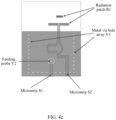
- FIG. 4a to FIG. 4c are other schematic structural diagrams of a dual-polarized antenna according to an embodiment of the present invention.
- the dual-polarized antenna includes an H-plane horn antenna and a planar end-fire antenna
- the H-plane horn antenna includes a metal via hole array V1, a metal floor G1, a metal floor G2, and a first feeding part
- the planar end-fire antenna includes a second feeding part and a radiation patch R1.
- An antenna plane of the dual-polarized antenna is parallel to the metal floor G1 and the metal floor G2.
- the metal floor G1 is parallel to the metal floor G2, the metal via hole array V1 is disposed between the metal floor G1 and the metal floor G2, the metal via hole array V1 includes three metal via hole arrays that are in a shape of a half-encircled rectangle, the metal via hole array V1 is located between the metal floor G1 and the metal floor G1, the metal via hole array V1 includes a plurality of metal via holes perpendicular to the metal floor G1 and the metal floor G2, a top end of each metal via hole is connected to the metal floor G1, and a bottom end of each metal via hole is connected to the metal floor G2.
- the metal floor G1, the metal floor G2, and the metal via hole array V1 form a waveguide cavity
- the metal via hole array V1 is used as a side wall of the waveguide cavity
- the metal floor G1 is used as a top surface of the waveguide cavity
- the metal floor G2 is used as a bottom surface of the waveguide cavity.
- the first feeding part is configured to feed the waveguide cavity, to excite the waveguide cavity to generate an electromagnetic wave signal, where a polarization direction of the generated electromagnetic wave signal is perpendicular to the antenna plane.
- the radiation patch R1 is parallel to the metal floor G1 and the metal floor G2, and the second feeding part is configured to feed the radiation patch R1, to excite the radiation patch R1 to generate an electromagnetic wave signal.
- FIG. 4b is a schematic side view of the dual-polarized antenna.
- the dual-polarized antenna further includes a dielectric plate L1 and a dielectric plate L2.
- the antenna plane of the dual-polarized antenna is the dielectric plate L1, the dielectric plate L1 is located on an upper layer of the metal floor G1, the dielectric plate L2 is located between the metal floor G1 and the metal floor G2, and a plurality of through holes for the metal via hole array V1 to pass through are disposed on the dielectric plate L2.
- FIG. 4c is a schematic front view of the dual-polarized antenna.
- the first feeding part includes a microstrip S 1 and a feeding probe V2.
- a through hole is disposed on an upper surface of the dielectric plate L1, and the feeding probe V2 is located in the through hole.
- the planar end-fire antenna is a Yagi antenna
- the second feeding part includes a microstrip S2
- the microstrip S2 may be an S-shaped cable
- the radiation patch R1 is disposed on the upper surface of the dielectric plate L1, where the radiation patch R1 may include a plurality of metal patches parallel to a horn mouth of the H-plane horn antenna.
- the dual-polarized antenna is the planar antenna
- the dual-polarized antenna includes the H-plane horn antenna based on an SIW and the Yagi antenna
- a maximum radiation direction of the dual-polarized antenna is parallel to an antenna plane and perpendicular to the horn mouth
- a polarization direction of the H-plane horn antenna is perpendicular to the antenna plane and perpendicular to the maximum radiation direction
- a polarization direction of the Yagi antenna is parallel to the antenna plane and perpendicular to the maximum radiation direction.
- the radio frequency circuit may be disposed in a reverse direction of the maximum radiation direction of the dual-polarized antenna, and is located on a same circuit board as the dual-polarized antenna, a feature of a low profile is implemented, and the radio frequency circuit and the dual-polarized antenna do not need to be connected by using an interconnection plug, thereby reducing an insertion loss and reducing an assembly difficulty.
- a feeding layer does not need to be introduced in the dual-polarized antenna, thereby reducing a thickness of the antenna.
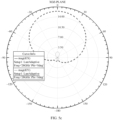
- FIG. 5a to FIG. 5d are electric field radiation patterns of a dual-polarized antenna according to an embodiment of the present invention.
- a three-dimensional coordinate system is set for the dual-polarized antenna, and an antenna plane is parallel to a YOZ plane.
- FIG. 5a is an electric field radiation pattern of an H-plane horn antenna in an XOZ plane
- FIG. 5b is an electric field radiation pattern of the H-plane horn antenna in a YOZ plane
- FIG. 5c is an electric field radiation pattern of a planar end-fire antenna in the XOZ plane
- FIG. 5d is an electric field radiation pattern of the planar end-fire antenna in the YOZ plane.
- maximum radiation directions of the H-plane horn antenna and the planar end-fire antenna are both +Z-axis directions, and the maximum radiation directions are parallel to the antenna plane (that is, the YOZ plane).
- a direction of a maximum electric field of the H-plane horn antenna is an X-axis direction and is perpendicular to the antenna plane, and polarization in one direction (for example, vertical polarization) is implemented.
- a direction of a maximum electric field of the planar end-fire antenna is a Y-axis direction and is parallel to the antenna plane, and polarization in another direction (for example, horizontal polarization) orthogonal to the polarization direction of the H-plane horn antenna is implemented.
Landscapes
- Variable-Direction Aerials And Aerial Arrays (AREA)
- Waveguide Aerials (AREA)
Claims (10)
- Antenne à double polarisation, comprenant une antenne cornet à plan H et une antenne planaire à rayonnement longitudinal, dans laquellel'antenne à double polarisation est une antenne planaire, une direction de polarisation de l'antenne cornet à plan H est perpendiculaire à un plan d'antenne de l'antenne à double polarisation, une direction de polarisation de l'antenne planaire à rayonnement longitudinal est parallèle au plan d'antenne, la direction de polarisation de l'antenne cornet à plan H est perpendiculaire à la direction de polarisation de l'antenne planaire à rayonnement longitudinal, une direction de rayonnement maximale de l'antenne à double polarisation est parallèle au plan de l'antenne, et la direction de rayonnement maximal de l'antenne à double polarisation est parallèle au plan de l'antenne, et la direction de rayonnement maximal de l'antenne à double polarisation est perpendiculaire à la direction de polarisation de l'antenne cornet à plan H et à la direction de polarisation de l'antenne planaire à rayonnement longitudinal ;dans laquelle l'antenne cornet à plan H comprend une première partie d'alimentation, un réseau de trous traversants métalliques (V1), un premier fond métallique (G1) et un second fond métallique (G2), dans laquelle le réseau de trous traversants métalliques (V1) comprend un premier réseau de trous métalliques et un second réseau de trous traversants métalliques, et le premier fond métallique (G1) et le second fond métallique (G2) sont parallèles au plan d'antenne ; le premier fond métallique (G1) est parallèle au second fond métallique (G2), et le réseau de trous traversants métalliques (V1) est situé entre le premier fond métallique (G1) et le second fond métallique (G2) ; une extrémité supérieure de chaque trou traversant métallique dans le réseau de trous traversants métalliques (V1) est connectée électriquement au premier fond métallique (G1), et une extrémité inférieure de chaque trou traversant métallique est connectée au second fond métallique (G2) ; le premier réseau de trous traversants métalliques et le second réseau de trous traversants métalliques sont perpendiculaires au premier fond métallique (G1) et au second fond métallique (G2) ; et le premier fond métallique (G1), le second fond métallique (G2) et le réseau de trous traversants métalliques (V1) forment une cavité de guide d'ondes, et la première partie d'alimentation est configurée pour alimenter la cavité de guide d'ondes, le premier réseau de trous traversants métalliques et le second réseau de trous traversants métalliques étant utilisés comme deux parois latérales de la cavité de guide d'ondes, le premier fond métallique (G1) est utilisé comme surface supérieure de la cavité de guide d'ondes, et le second fond métallique (G2) est utilisé comme fond de surface de la cavité du guide d'ondes ; etl'antenne planaire à rayonnement longitudinal comprend une seconde partie d'alimentation et une plaque de rayonnement (R1), dans laquelle la seconde partie d'alimentation est configurée pour alimenter la plaque de rayonnement (R1), et la plaque de rayonnement (R1) est parallèle au premier fond métallique (G1) et au second fond métallique (G2).
- Antenne selon la revendication 1, dans laquelle une distance entre le premier réseau de trous traversants métalliques et le second réseau de trous traversants métalliques est constante le long d'une partie de la cavité du guide d'ondes le long d'une direction de rayonnement maximal, puis la distance entre le premier réseau de trous traversants métalliques et le second réseau de trous traversants métalliques augmente progressivement de manière linéaire le long d'une seconde partie de la cavité du guide d'ondes le long d'une direction de rayonnement maximal.
- Antenne selon la revendication 1 ou 2, comprenant également une première plaque diélectrique (L1), une seconde plaque diélectrique (L2), une première couche d'alimentation (F1) et une seconde couche d'alimentation (F2), dans laquelle
la première plaque diélectrique est disposée sur une surface inférieure du premier fond métallique, et la première couche d'alimentation est disposée sur une surface supérieure du premier fond métallique ; la seconde plaque diélectrique est disposée sur une surface supérieure du second fond métallique, et la seconde couche d'alimentation est disposée entre une surface inférieure de la première plaque diélectrique et une surface supérieure de la seconde plaque diélectrique ; et la plaque de rayonnement est disposée entre une surface inférieure de la seconde couche d'alimentation et la surface supérieure de la seconde plaque diélectrique, et la seconde partie d'alimentation est disposée entre une surface supérieure de la seconde couche d'alimentation et une surface inférieure de la première plaque diélectrique. - Antenne selon la revendication 3, dans laquellela première partie d'alimentation comprend un premier microruban (S1) et une sonde d'alimentation (V2), dans laquelle le premier microruban est connecté électriquement à la sonde d'alimentation ; le premier microruban est disposé sur une surface supérieure de la première couche d'alimentation, un trou traversant perpendiculaire à la première couche d'alimentation est disposé sur la surface supérieure de la première couche d'alimentation, et la sonde d'alimentation est située dans le trou traversant ; etla seconde partie d'alimentation comprend un second microruban (S2), dans laquelle le second microruban est disposé entre la surface inférieure de la première plaque diélectrique et la surface supérieure de la seconde couche d'alimentation, et le second microruban se trouve dans la cavité de guide d'ondes.
- Antenne selon la revendication 4, dans laquelle l'antenne planaire à rayonnement longitudinal est une antenne Vivaldi, une zone rectangulaire et une zone en forme de cornet qui sont en communication l'une avec l'autre sont formées dans une zone qui est de la surface supérieure de la seconde couche diélectrique et qui n'est pas recouverte par la plaque de rayonnement, et une bouche en forme de cornet de la zone en forme de cornet est perpendiculaire à la direction de rayonnement maximal.
- Antenne selon la revendication 4 ou 5, dans laquelle le second microruban comprend deux câbles perpendiculaires entre eux.
- Antenne selon la revendication 1, comprenant également une première plaque diélectrique (L1) et une seconde plaque diélectrique (L2), dans laquelle
le premier fond métallique est disposé entre une surface inférieure de la première plaque diélectrique et une surface supérieure de la seconde plaque diélectrique, et le second fond métallique est disposé sur une surface inférieure de la seconde plaque diélectrique. - Antenne selon la revendication 7, dans laquelle la première partie d'alimentation comprend un premier microruban (S1) et une sonde d'alimentation (V2), dans laquelle le premier microruban est disposé sur une surface supérieure de la première plaque diélectrique, le premier microruban est électriquement connecté à la sonde d'alimentation, un trou traversant est disposé sur la surface supérieure de la première plaque diélectrique, et la sonde d'alimentation est située dans le trou traversant ; et la seconde partie d'alimentation comprend un second microruban, et le second microruban et la plaque de rayonnement sont disposés sur la première plaque diélectrique.
- Appareil frontal radiofréquence, comprenant une carte de circuit imprimé radiofréquence, un circuit radiofréquence et l'antenne à double polarisation selon l'une quelconque des revendications 1 à 8, dans lequel l'antenne à double polarisation et le circuit radiofréquence sont disposés sur la carte de circuit imprimé radiofréquence, et un plan d'antenne de l'antenne à double polarisation est parallèle à la carte de circuit imprimé radiofréquence.
- Dispositif de communication, dans lequel le dispositif de communication comprend l'appareil frontal radiofréquence selon la revendication 9.
Applications Claiming Priority (2)
| Application Number | Priority Date | Filing Date | Title |
|---|---|---|---|
| CN201810080107.XA CN110098492B (zh) | 2018-01-27 | 2018-01-27 | 一种双极化天线、射频前端装置和通信设备 |
| PCT/CN2018/122934 WO2019144739A1 (fr) | 2018-01-27 | 2018-12-22 | Antenne à double polarisation, appareil frontal radiofréquence et dispositif de communication |
Publications (3)
| Publication Number | Publication Date |
|---|---|
| EP3716407A1 EP3716407A1 (fr) | 2020-09-30 |
| EP3716407A4 EP3716407A4 (fr) | 2020-12-23 |
| EP3716407B1 true EP3716407B1 (fr) | 2024-08-28 |
Family
ID=67394467
Family Applications (1)
| Application Number | Title | Priority Date | Filing Date |
|---|---|---|---|
| EP18902585.1A Active EP3716407B1 (fr) | 2018-01-27 | 2018-12-22 | Antenne à double polarisation, appareil frontal radiofréquence et dispositif de communication |
Country Status (4)
| Country | Link |
|---|---|
| US (1) | US11251541B2 (fr) |
| EP (1) | EP3716407B1 (fr) |
| CN (1) | CN110098492B (fr) |
| WO (1) | WO2019144739A1 (fr) |
Families Citing this family (16)
| Publication number | Priority date | Publication date | Assignee | Title |
|---|---|---|---|---|
| EP3793029A4 (fr) * | 2018-05-10 | 2022-01-12 | KMW Inc. | Antenne à double polarisation et réseau d'antennes |
| CN111613896B (zh) * | 2020-06-28 | 2024-11-01 | 湖南大学 | 超宽带低剖面定向辐射斜锥天线 |
| CN111969310A (zh) * | 2020-08-10 | 2020-11-20 | 康凯科技(杭州)股份有限公司 | 一种天线系统 |
| CN112151958A (zh) * | 2020-09-25 | 2020-12-29 | 重庆两江卫星移动通信有限公司 | 一种平面端射圆极化天线 |
| CN112701455B (zh) * | 2020-11-23 | 2023-03-28 | 扬州船用电子仪器研究所(中国船舶重工集团公司第七二三研究所) | 一种大倍频程超宽角扫描相控阵天线 |
| CN112787102B (zh) * | 2020-12-29 | 2022-09-23 | 中国人民解放军战略支援部队航天工程大学 | 采用半开放式siw喇叭天线作馈源的平面伦伯透镜天线 |
| CN112993592B (zh) * | 2021-02-08 | 2023-06-09 | 维沃移动通信有限公司 | 天线封装模组及电子设备 |
| CN114914666B (zh) * | 2021-02-10 | 2024-03-26 | 华为技术有限公司 | 一种天线及电子设备 |
| CN113540778B (zh) * | 2021-07-02 | 2022-11-22 | 西南交通大学 | 一种超表面覆盖的垂直极化平面宽带端射天线 |
| CN113794049B (zh) * | 2021-08-09 | 2023-05-30 | 北京交通大学 | 基于多层层叠型介质集成波导的三维基片集成天线 |
| CN113922051B (zh) * | 2021-11-03 | 2023-05-26 | 西安邮电大学 | 一种具有自解耦特性的宽带mimo天线 |
| CN114914715A (zh) * | 2022-04-25 | 2022-08-16 | 上海交通大学 | 一种融合Vivaldi天线阵与散热片的一体化结构 |
| CN115693117A (zh) * | 2022-10-23 | 2023-02-03 | 哈尔滨工业大学(威海) | 基于siw喇叭和ebg加载振子天线的极化分集天线 |
| CN116759816B (zh) * | 2023-01-13 | 2023-10-27 | 安徽大学 | 基于基片集成波导的双频双极化天线 |
| CN116581538B (zh) * | 2023-06-05 | 2026-03-27 | 南京理工大学 | 一种具有新型馈电结构的宽带低剖面双极化Vivaldi天线单元 |
| CN116938276B (zh) * | 2023-09-14 | 2023-12-22 | 成都锐芯盛通电子科技有限公司 | 一种双极化多通道相控阵sip模块 |
Family Cites Families (16)
| Publication number | Priority date | Publication date | Assignee | Title |
|---|---|---|---|---|
| US4672384A (en) * | 1984-12-31 | 1987-06-09 | Raytheon Company | Circularly polarized radio frequency antenna |
| US6538614B2 (en) * | 2001-04-17 | 2003-03-25 | Lucent Technologies Inc. | Broadband antenna structure |
| US7808439B2 (en) * | 2007-09-07 | 2010-10-05 | University Of Tennessee Reserch Foundation | Substrate integrated waveguide antenna array |
| WO2011095969A1 (fr) * | 2010-02-02 | 2011-08-11 | Technion Research & Development Foundation Ltd. | Antenne à fentes amincie compacte |
| CN202121061U (zh) * | 2011-04-29 | 2012-01-18 | 刘建江 | 辐射单元及辐射阵列 |
| CN102255144B (zh) * | 2011-04-29 | 2015-04-22 | 刘建江 | 辐射单元、辐射阵列及加工成型方法 |
| US8422540B1 (en) * | 2012-06-21 | 2013-04-16 | CBF Networks, Inc. | Intelligent backhaul radio with zero division duplexing |
| US9203159B2 (en) * | 2011-09-16 | 2015-12-01 | International Business Machines Corporation | Phased-array transceiver |
| CN103618145B (zh) * | 2013-11-29 | 2016-03-23 | 东南大学 | 薄基片准八木平面喇叭天线 |
| KR101920748B1 (ko) * | 2014-10-20 | 2018-11-21 | 가부시키가이샤 무라타 세이사쿠쇼 | 무선통신 모듈 |
| EP3266066B1 (fr) * | 2015-03-03 | 2022-06-15 | The Government of the United States of America as represented by the Secretary of the Navy | Élément d'antenne à bande ultra-large à bande passante décadique à faible polarisation croisée |
| US10516201B2 (en) * | 2016-04-11 | 2019-12-24 | Samsung Electronics Co., Ltd. | Wireless communication system including polarization-agile phased-array antenna |
| CN106299618B (zh) * | 2016-08-19 | 2019-06-18 | 四川中测微格科技有限公司 | 一种基片集成波导平面端射圆极化天线 |
| CN106450702B (zh) * | 2016-11-23 | 2019-10-18 | 上海无线电设备研究所 | 一种宽带双线极化锥削槽天线 |
| CN107369887A (zh) * | 2017-06-28 | 2017-11-21 | 山东航天电子技术研究所 | 一种高倍频程双极化Vivaldi天线 |
| US10484038B1 (en) * | 2019-06-27 | 2019-11-19 | Psemi Corporation | Phased array transceiver with built-in phase interferometer |
-
2018
- 2018-01-27 CN CN201810080107.XA patent/CN110098492B/zh active Active
- 2018-12-22 EP EP18902585.1A patent/EP3716407B1/fr active Active
- 2018-12-22 WO PCT/CN2018/122934 patent/WO2019144739A1/fr not_active Ceased
-
2020
- 2020-07-08 US US16/923,287 patent/US11251541B2/en active Active
Also Published As
| Publication number | Publication date |
|---|---|
| EP3716407A4 (fr) | 2020-12-23 |
| CN110098492B (zh) | 2020-07-24 |
| WO2019144739A1 (fr) | 2019-08-01 |
| US11251541B2 (en) | 2022-02-15 |
| EP3716407A1 (fr) | 2020-09-30 |
| CN110098492A (zh) | 2019-08-06 |
| US20200343649A1 (en) | 2020-10-29 |
Similar Documents
| Publication | Publication Date | Title |
|---|---|---|
| US11251541B2 (en) | Dual-polarized antenna, radio frequency front-end apparatus, and communications device | |
| EP3975337B1 (fr) | Unité d'antenne et dispositif terminal | |
| US11688953B2 (en) | Terminal device | |
| US10978811B2 (en) | Slot antenna arrays for millimeter-wave communication systems | |
| CN100416917C (zh) | 天线装置 | |
| EP3859879A1 (fr) | Dispositif terminal | |
| CN111052508B (zh) | 垂直端射天线 | |
| EP4340127A1 (fr) | Antenne à large bande, antenne de boîtier et dispositif de communication | |
| CN113161720B (zh) | 具有高隔离度和低交叉极化电平的天线、基站和终端 | |
| KR20170116558A (ko) | 편파-가변 위상 어레이 안테나를 포함하는 무선 통신 장치 | |
| CN101478079B (zh) | 阵列天线以及使用其的电子装置 | |
| WO2021104191A1 (fr) | Unité d'antenne et dispositif électronique | |
| Hwang et al. | Cavity-backed stacked patch array antenna with dual polarization for mmWave 5G base stations | |
| EP3685512B1 (fr) | Système d'antenne pour un dispositif de communication sans fil | |
| US11594823B2 (en) | Discrete antenna module with via wall structure | |
| US20250226592A1 (en) | Antenna apparatus and wireless communication device | |
| CN109560387B (zh) | 一种用于移动终端的毫米波双极化天线 | |
| CN116073113A (zh) | 一种多频天线及通信设备 | |
| WO2022134786A1 (fr) | Antenne et dispositif de communication | |
| US20250379363A1 (en) | Antenna element, antenna system, and communication device | |
| CN114696080A (zh) | 端射天线、封装天线和通讯设备 | |
| EP3742553B1 (fr) | Antenne à polarisation verticale et dispositif terminal | |
| CN110011028B (zh) | 一种天线系统、通讯终端和基站 | |
| CN112421221A (zh) | 天线模组及客户前置设备 | |
| Alkaraki et al. | mm-Wave Low Cost MIMO Antennas with Beam Switching Capabilities Fabricated Using 3D Printing for 5G Communication Systems |
Legal Events
| Date | Code | Title | Description |
|---|---|---|---|
| STAA | Information on the status of an ep patent application or granted ep patent |
Free format text: STATUS: THE INTERNATIONAL PUBLICATION HAS BEEN MADE |
|
| PUAI | Public reference made under article 153(3) epc to a published international application that has entered the european phase |
Free format text: ORIGINAL CODE: 0009012 |
|
| STAA | Information on the status of an ep patent application or granted ep patent |
Free format text: STATUS: REQUEST FOR EXAMINATION WAS MADE |
|
| 17P | Request for examination filed |
Effective date: 20200624 |
|
| AK | Designated contracting states |
Kind code of ref document: A1 Designated state(s): AL AT BE BG CH CY CZ DE DK EE ES FI FR GB GR HR HU IE IS IT LI LT LU LV MC MK MT NL NO PL PT RO RS SE SI SK SM TR |
|
| AX | Request for extension of the european patent |
Extension state: BA ME |
|
| A4 | Supplementary search report drawn up and despatched |
Effective date: 20201123 |
|
| RIC1 | Information provided on ipc code assigned before grant |
Ipc: H01Q 11/10 20060101ALI20201117BHEP Ipc: H01Q 13/08 20060101ALI20201117BHEP Ipc: H01Q 25/00 20060101AFI20201117BHEP Ipc: H01Q 13/06 20060101ALI20201117BHEP Ipc: H01Q 13/02 20060101ALI20201117BHEP Ipc: H01Q 21/24 20060101ALI20201117BHEP |
|
| DAV | Request for validation of the european patent (deleted) | ||
| DAX | Request for extension of the european patent (deleted) | ||
| STAA | Information on the status of an ep patent application or granted ep patent |
Free format text: STATUS: EXAMINATION IS IN PROGRESS |
|
| 17Q | First examination report despatched |
Effective date: 20220523 |
|
| GRAP | Despatch of communication of intention to grant a patent |
Free format text: ORIGINAL CODE: EPIDOSNIGR1 |
|
| STAA | Information on the status of an ep patent application or granted ep patent |
Free format text: STATUS: GRANT OF PATENT IS INTENDED |
|
| RIC1 | Information provided on ipc code assigned before grant |
Ipc: H01Q 13/06 20060101ALI20240315BHEP Ipc: H01Q 13/08 20060101ALI20240315BHEP Ipc: H01Q 21/24 20060101ALI20240315BHEP Ipc: H01Q 13/02 20060101ALI20240315BHEP Ipc: H01Q 25/00 20060101AFI20240315BHEP |
|
| INTG | Intention to grant announced |
Effective date: 20240408 |
|
| GRAS | Grant fee paid |
Free format text: ORIGINAL CODE: EPIDOSNIGR3 |
|
| GRAA | (expected) grant |
Free format text: ORIGINAL CODE: 0009210 |
|
| STAA | Information on the status of an ep patent application or granted ep patent |
Free format text: STATUS: THE PATENT HAS BEEN GRANTED |
|
| AK | Designated contracting states |
Kind code of ref document: B1 Designated state(s): AL AT BE BG CH CY CZ DE DK EE ES FI FR GB GR HR HU IE IS IT LI LT LU LV MC MK MT NL NO PL PT RO RS SE SI SK SM TR |
|
| REG | Reference to a national code |
Ref country code: GB Ref legal event code: FG4D |
|
| REG | Reference to a national code |
Ref country code: CH Ref legal event code: EP |
|
| REG | Reference to a national code |
Ref country code: DE Ref legal event code: R096 Ref document number: 602018073806 Country of ref document: DE |
|
| REG | Reference to a national code |
Ref country code: IE Ref legal event code: FG4D |
|
| REG | Reference to a national code |
Ref country code: LT Ref legal event code: MG9D |
|
| PG25 | Lapsed in a contracting state [announced via postgrant information from national office to epo] |
Ref country code: NO Free format text: LAPSE BECAUSE OF FAILURE TO SUBMIT A TRANSLATION OF THE DESCRIPTION OR TO PAY THE FEE WITHIN THE PRESCRIBED TIME-LIMIT Effective date: 20241128 |
|
| REG | Reference to a national code |
Ref country code: AT Ref legal event code: MK05 Ref document number: 1719029 Country of ref document: AT Kind code of ref document: T Effective date: 20240828 |
|
| PG25 | Lapsed in a contracting state [announced via postgrant information from national office to epo] |
Ref country code: PT Free format text: LAPSE BECAUSE OF FAILURE TO SUBMIT A TRANSLATION OF THE DESCRIPTION OR TO PAY THE FEE WITHIN THE PRESCRIBED TIME-LIMIT Effective date: 20241230 Ref country code: NL Free format text: LAPSE BECAUSE OF FAILURE TO SUBMIT A TRANSLATION OF THE DESCRIPTION OR TO PAY THE FEE WITHIN THE PRESCRIBED TIME-LIMIT Effective date: 20240828 Ref country code: FI Free format text: LAPSE BECAUSE OF FAILURE TO SUBMIT A TRANSLATION OF THE DESCRIPTION OR TO PAY THE FEE WITHIN THE PRESCRIBED TIME-LIMIT Effective date: 20240828 Ref country code: GR Free format text: LAPSE BECAUSE OF FAILURE TO SUBMIT A TRANSLATION OF THE DESCRIPTION OR TO PAY THE FEE WITHIN THE PRESCRIBED TIME-LIMIT Effective date: 20241129 Ref country code: PL Free format text: LAPSE BECAUSE OF FAILURE TO SUBMIT A TRANSLATION OF THE DESCRIPTION OR TO PAY THE FEE WITHIN THE PRESCRIBED TIME-LIMIT Effective date: 20240828 |
|
| PG25 | Lapsed in a contracting state [announced via postgrant information from national office to epo] |
Ref country code: BG Free format text: LAPSE BECAUSE OF FAILURE TO SUBMIT A TRANSLATION OF THE DESCRIPTION OR TO PAY THE FEE WITHIN THE PRESCRIBED TIME-LIMIT Effective date: 20240828 |
|
| PG25 | Lapsed in a contracting state [announced via postgrant information from national office to epo] |
Ref country code: LV Free format text: LAPSE BECAUSE OF FAILURE TO SUBMIT A TRANSLATION OF THE DESCRIPTION OR TO PAY THE FEE WITHIN THE PRESCRIBED TIME-LIMIT Effective date: 20240828 |
|
| REG | Reference to a national code |
Ref country code: NL Ref legal event code: MP Effective date: 20240828 |
|
| PG25 | Lapsed in a contracting state [announced via postgrant information from national office to epo] |
Ref country code: IS Free format text: LAPSE BECAUSE OF FAILURE TO SUBMIT A TRANSLATION OF THE DESCRIPTION OR TO PAY THE FEE WITHIN THE PRESCRIBED TIME-LIMIT Effective date: 20241228 Ref country code: AT Free format text: LAPSE BECAUSE OF FAILURE TO SUBMIT A TRANSLATION OF THE DESCRIPTION OR TO PAY THE FEE WITHIN THE PRESCRIBED TIME-LIMIT Effective date: 20240828 |
|
| PG25 | Lapsed in a contracting state [announced via postgrant information from national office to epo] |
Ref country code: HR Free format text: LAPSE BECAUSE OF FAILURE TO SUBMIT A TRANSLATION OF THE DESCRIPTION OR TO PAY THE FEE WITHIN THE PRESCRIBED TIME-LIMIT Effective date: 20240828 |
|
| PG25 | Lapsed in a contracting state [announced via postgrant information from national office to epo] |
Ref country code: RS Free format text: LAPSE BECAUSE OF FAILURE TO SUBMIT A TRANSLATION OF THE DESCRIPTION OR TO PAY THE FEE WITHIN THE PRESCRIBED TIME-LIMIT Effective date: 20241128 Ref country code: ES Free format text: LAPSE BECAUSE OF FAILURE TO SUBMIT A TRANSLATION OF THE DESCRIPTION OR TO PAY THE FEE WITHIN THE PRESCRIBED TIME-LIMIT Effective date: 20240828 |
|
| PG25 | Lapsed in a contracting state [announced via postgrant information from national office to epo] |
Ref country code: RS Free format text: LAPSE BECAUSE OF FAILURE TO SUBMIT A TRANSLATION OF THE DESCRIPTION OR TO PAY THE FEE WITHIN THE PRESCRIBED TIME-LIMIT Effective date: 20241128 Ref country code: PT Free format text: LAPSE BECAUSE OF FAILURE TO SUBMIT A TRANSLATION OF THE DESCRIPTION OR TO PAY THE FEE WITHIN THE PRESCRIBED TIME-LIMIT Effective date: 20241230 Ref country code: PL Free format text: LAPSE BECAUSE OF FAILURE TO SUBMIT A TRANSLATION OF THE DESCRIPTION OR TO PAY THE FEE WITHIN THE PRESCRIBED TIME-LIMIT Effective date: 20240828 Ref country code: NO Free format text: LAPSE BECAUSE OF FAILURE TO SUBMIT A TRANSLATION OF THE DESCRIPTION OR TO PAY THE FEE WITHIN THE PRESCRIBED TIME-LIMIT Effective date: 20241128 Ref country code: NL Free format text: LAPSE BECAUSE OF FAILURE TO SUBMIT A TRANSLATION OF THE DESCRIPTION OR TO PAY THE FEE WITHIN THE PRESCRIBED TIME-LIMIT Effective date: 20240828 Ref country code: LV Free format text: LAPSE BECAUSE OF FAILURE TO SUBMIT A TRANSLATION OF THE DESCRIPTION OR TO PAY THE FEE WITHIN THE PRESCRIBED TIME-LIMIT Effective date: 20240828 Ref country code: IS Free format text: LAPSE BECAUSE OF FAILURE TO SUBMIT A TRANSLATION OF THE DESCRIPTION OR TO PAY THE FEE WITHIN THE PRESCRIBED TIME-LIMIT Effective date: 20241228 Ref country code: HR Free format text: LAPSE BECAUSE OF FAILURE TO SUBMIT A TRANSLATION OF THE DESCRIPTION OR TO PAY THE FEE WITHIN THE PRESCRIBED TIME-LIMIT Effective date: 20240828 Ref country code: GR Free format text: LAPSE BECAUSE OF FAILURE TO SUBMIT A TRANSLATION OF THE DESCRIPTION OR TO PAY THE FEE WITHIN THE PRESCRIBED TIME-LIMIT Effective date: 20241129 Ref country code: FI Free format text: LAPSE BECAUSE OF FAILURE TO SUBMIT A TRANSLATION OF THE DESCRIPTION OR TO PAY THE FEE WITHIN THE PRESCRIBED TIME-LIMIT Effective date: 20240828 Ref country code: ES Free format text: LAPSE BECAUSE OF FAILURE TO SUBMIT A TRANSLATION OF THE DESCRIPTION OR TO PAY THE FEE WITHIN THE PRESCRIBED TIME-LIMIT Effective date: 20240828 Ref country code: BG Free format text: LAPSE BECAUSE OF FAILURE TO SUBMIT A TRANSLATION OF THE DESCRIPTION OR TO PAY THE FEE WITHIN THE PRESCRIBED TIME-LIMIT Effective date: 20240828 Ref country code: AT Free format text: LAPSE BECAUSE OF FAILURE TO SUBMIT A TRANSLATION OF THE DESCRIPTION OR TO PAY THE FEE WITHIN THE PRESCRIBED TIME-LIMIT Effective date: 20240828 |
|
| PG25 | Lapsed in a contracting state [announced via postgrant information from national office to epo] |
Ref country code: SM Free format text: LAPSE BECAUSE OF FAILURE TO SUBMIT A TRANSLATION OF THE DESCRIPTION OR TO PAY THE FEE WITHIN THE PRESCRIBED TIME-LIMIT Effective date: 20240828 Ref country code: DK Free format text: LAPSE BECAUSE OF FAILURE TO SUBMIT A TRANSLATION OF THE DESCRIPTION OR TO PAY THE FEE WITHIN THE PRESCRIBED TIME-LIMIT Effective date: 20240828 Ref country code: RO Free format text: LAPSE BECAUSE OF FAILURE TO SUBMIT A TRANSLATION OF THE DESCRIPTION OR TO PAY THE FEE WITHIN THE PRESCRIBED TIME-LIMIT Effective date: 20240828 |
|
| PG25 | Lapsed in a contracting state [announced via postgrant information from national office to epo] |
Ref country code: EE Free format text: LAPSE BECAUSE OF FAILURE TO SUBMIT A TRANSLATION OF THE DESCRIPTION OR TO PAY THE FEE WITHIN THE PRESCRIBED TIME-LIMIT Effective date: 20240828 |
|
| PG25 | Lapsed in a contracting state [announced via postgrant information from national office to epo] |
Ref country code: CZ Free format text: LAPSE BECAUSE OF FAILURE TO SUBMIT A TRANSLATION OF THE DESCRIPTION OR TO PAY THE FEE WITHIN THE PRESCRIBED TIME-LIMIT Effective date: 20240828 |
|
| PG25 | Lapsed in a contracting state [announced via postgrant information from national office to epo] |
Ref country code: IT Free format text: LAPSE BECAUSE OF FAILURE TO SUBMIT A TRANSLATION OF THE DESCRIPTION OR TO PAY THE FEE WITHIN THE PRESCRIBED TIME-LIMIT Effective date: 20240828 Ref country code: SK Free format text: LAPSE BECAUSE OF FAILURE TO SUBMIT A TRANSLATION OF THE DESCRIPTION OR TO PAY THE FEE WITHIN THE PRESCRIBED TIME-LIMIT Effective date: 20240828 |
|
| REG | Reference to a national code |
Ref country code: DE Ref legal event code: R097 Ref document number: 602018073806 Country of ref document: DE |
|
| PLBE | No opposition filed within time limit |
Free format text: ORIGINAL CODE: 0009261 |
|
| STAA | Information on the status of an ep patent application or granted ep patent |
Free format text: STATUS: NO OPPOSITION FILED WITHIN TIME LIMIT |
|
| PG25 | Lapsed in a contracting state [announced via postgrant information from national office to epo] |
Ref country code: MC Free format text: LAPSE BECAUSE OF FAILURE TO SUBMIT A TRANSLATION OF THE DESCRIPTION OR TO PAY THE FEE WITHIN THE PRESCRIBED TIME-LIMIT Effective date: 20240828 |
|
| REG | Reference to a national code |
Ref country code: CH Ref legal event code: PL |
|
| 26N | No opposition filed |
Effective date: 20250530 |
|
| PG25 | Lapsed in a contracting state [announced via postgrant information from national office to epo] |
Ref country code: LU Free format text: LAPSE BECAUSE OF NON-PAYMENT OF DUE FEES Effective date: 20241222 |
|
| PG25 | Lapsed in a contracting state [announced via postgrant information from national office to epo] |
Ref country code: SE Free format text: LAPSE BECAUSE OF FAILURE TO SUBMIT A TRANSLATION OF THE DESCRIPTION OR TO PAY THE FEE WITHIN THE PRESCRIBED TIME-LIMIT Effective date: 20240828 |
|
| REG | Reference to a national code |
Ref country code: BE Ref legal event code: MM Effective date: 20241231 |
|
| PG25 | Lapsed in a contracting state [announced via postgrant information from national office to epo] |
Ref country code: BE Free format text: LAPSE BECAUSE OF NON-PAYMENT OF DUE FEES Effective date: 20241231 |
|
| PG25 | Lapsed in a contracting state [announced via postgrant information from national office to epo] |
Ref country code: FR Free format text: LAPSE BECAUSE OF NON-PAYMENT OF DUE FEES Effective date: 20241231 |
|
| PG25 | Lapsed in a contracting state [announced via postgrant information from national office to epo] |
Ref country code: CH Free format text: LAPSE BECAUSE OF NON-PAYMENT OF DUE FEES Effective date: 20241231 |
|
| PG25 | Lapsed in a contracting state [announced via postgrant information from national office to epo] |
Ref country code: IE Free format text: LAPSE BECAUSE OF NON-PAYMENT OF DUE FEES Effective date: 20241222 |
|
| PGFP | Annual fee paid to national office [announced via postgrant information from national office to epo] |
Ref country code: DE Payment date: 20251104 Year of fee payment: 8 |
|
| PGFP | Annual fee paid to national office [announced via postgrant information from national office to epo] |
Ref country code: GB Payment date: 20251030 Year of fee payment: 8 |