EP3716559B1 - Procédé de réduction de la puissance crête d'un signal d'entrée d'un dispositif d'émetteur par rapport à la puissance moyenne - Google Patents
Procédé de réduction de la puissance crête d'un signal d'entrée d'un dispositif d'émetteur par rapport à la puissance moyenne Download PDFInfo
- Publication number
- EP3716559B1 EP3716559B1 EP19164974.8A EP19164974A EP3716559B1 EP 3716559 B1 EP3716559 B1 EP 3716559B1 EP 19164974 A EP19164974 A EP 19164974A EP 3716559 B1 EP3716559 B1 EP 3716559B1
- Authority
- EP
- European Patent Office
- Prior art keywords
- signal
- input signal
- magnitude
- reduction
- compression
- Prior art date
- Legal status (The legal status is an assumption and is not a legal conclusion. Google has not performed a legal analysis and makes no representation as to the accuracy of the status listed.)
- Active
Links
Images


Classifications
-
- H—ELECTRICITY
- H04—ELECTRIC COMMUNICATION TECHNIQUE
- H04L—TRANSMISSION OF DIGITAL INFORMATION, e.g. TELEGRAPHIC COMMUNICATION
- H04L27/00—Modulated-carrier systems
- H04L27/26—Systems using multi-frequency codes
- H04L27/2601—Multicarrier modulation systems
- H04L27/2614—Peak power aspects
- H04L27/2623—Reduction thereof by clipping
- H04L27/2624—Reduction thereof by clipping by soft clipping
Definitions
- the invention relates to a method for reduction of signal peak to average power of an input signal, which is inputted to analog radio frequency stage of a transmitter device.
- the method is performed by a PAPR limiter, which is a unit of the transmitter device.
- Modern communication standards like LTE (long-term evolution) and NB-IoT (narrowband internet-of-things) deploy modulation schemes like OFDM (orthogonal frequency division multiplex) or SC-FDMA (single carrier frequency division multiple access) for transmission of synchronization, pilot and data signals.
- modulation schemes like OFDM (orthogonal frequency division multiplex) or SC-FDMA (single carrier frequency division multiple access) for transmission of synchronization, pilot and data signals.
- OFDM orthogonal frequency division multiplex
- SC-FDMA single carrier frequency division multiple access
- Spectral emissions comprise the RF (radio frequency) power of signals a device emits outside of its allocated frequency range. This characterizes the amount of distortions a certain device creates on other communication links that deploy the same or a different radio access technology.
- spectral masks To create a pass/fail criterion, so-called spectral masks have been provided, that define frequency dependent maximum power levels a device must not exceed. Reference is made to 3GPP TS 36.101. Since manufacturing tolerances can have a strong impact on spectral emissions, manufacturers tend to design their devices such that a certain margin exists between nominal design and spectral mask defined by standardization organizations.
- Error vector magnitude describes average and peak difference between transmitted modulated data signal and ideal modulation points in relation to average magnitude of the modulated data symbol.
- Transmitters in communication devices are usually designed according to the required maximum RF output power.
- Maximum RF power determines architecture, size, supply power consumption and hence cost of the device to a large extend.
- transmitters for OFDM or SC-FDMA suffer from the high PAPR of the signals to be transmitted.
- PAPR for OFDM signals can reach 14dB or more, which means that for an average output power of 100mW a peak power of about 2.5W must be supported by the transmitter architecture.
- FIG. 1 depicts power spectral density (PSD) over frequency for an uncompressed signal 3, a signal with low compression 4, and a signal with high compression 5, with the latter violating spectral mask requirements 6.
- PSD power spectral density
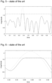
- FIG. 6 Impact on a typical SC-FDMA signal when applying such a method is illustrated in figure 6 including unwanted delay by filtering as a side effect.
- a combination of saturation and time domain filtering creates significantly less spectral emissions than in the digital saturation in time domain method, but filtering effort can be quite high, especially when the data path runs on a high sampling rate.
- Effort relates here to chip area and power consumption.
- other signals running in parallel must be delayed as well, e.g. the path for the phase signal in a polar transmitter architecture, increasing the overall effort as well.
- clipping and filtering in time as well as frequency domain Various methods have been introduced to combat spectrum emissions that apply clipping, frequency and time domain filtering. Extended methods comprising saturation, filtering in time and frequency domain provide best results in terms of signal properties (EVM and spectral emissions) but effort and delay are even higher than in methods using digital saturation and time domain filtering.
- the object of the present invention is to design a low complexity, low effort method to reduce PAPR of signals to be transmitted, for example signals which deploy OFDM or SC-FDMA. This targets a reduction of maximum power a transmit path has to be designed for, aiming reduction of complexity, size, cost, and power consumption. Nevertheless, requirements given by standardization bodies like 3GPP shall be met, especially concerning spectral mask and EVM.
- the input signal which is optimized by the inventive method has to be modulated by a bandlimited modulation scheme that possesses a special correlation between peak magnitude and slope, for example, an OFDM or SC-FDMA modulated input signal.
- the inventive method is performed by a peak to average power ratio (PAPR) limiter, which is a unit of the transmitter device. Parameters mth and sth are stored in a memory of the transmitter device and will be loaded during operation into the limiter unit.
- PAPR peak to average power ratio
- the invented method performs a signal compression sample by sample, hence on a per sample basis, which means that a selected compression function is applied to a certain sample of the input signal, without considering the history of the input signal in time. This requires much less effort in terms of chip area and power consumption than filter-based solutions.
- the method choses a certain non-linear compression function from a pre-defined set of functions as soon as the input signal magnitude passes a certain magnitude threshold mth.
- the magnitude threshold mth is an input parameter to the algorithm that is optimized according to system requirements, e.g. desired maximum PAPR, accepted spectral emissions, concrete modulation scheme etc.
- the choice is made using the first derivative of the input signal magnitude over time as a decision metric.
- the invented method uses digital signal processing which is in contrast to analog implementations better reproducible and parametrizable.
- the invented method switches between multiple compression functions based on the decision metric derived from the first-order derivative of the input signal magnitude over time. This improves performance with respect to spectral mask and EVM substantially compared with simple static compression methods.
- the inventive method comprises of a selection algorithm for a signal compression function and a signal processing block that performs the actual signal compression, aiming a reduction of PAPR to a certain target PAPR.
- the input signal possesses a very high PAPR which would require too much headroom in the design to cope with the high peak power. Since such very high peaks occur only infrequently, it is possible to compress the input signal magnitude, sacrificing some signal quality in terms of spectral emissions and EVM. Basic requirements for those two key characteristics must be met however.
- non-linear functions on single samples are used to perform compression of OFDM or SC-FDMA signals.
- Such functions f() can be used to reduce PAPR with acceptable loss of signal quality in terms of spectral emissions and EVM.
- the invented method exploits a property of OFDM or SC-FDMA signals: It can be observed that steepness of a rising signal slope is correlated to the maximum of the subsequent signal.
- the selection algorithm as part of the inventive method detects the moment when the input signal magnitude exceeds a certain magnitude threshold mth the first time.
- the first-order derivative over time of the input signal i.e. the magnitude difference of consecutive samples
- the metric is compared to a slope threshold sth, as another input parameter for the inventive method.
- Useful range for slope threshold depends on system parameters (e.g. sampling frequency), signal statistics and magnitude threshold. Within that useful range, the slope threshold may be optimized to suite individual needs. For example, extensive simulation will be used to obtain sth for a certain scenario.
- a compression function f 2 optimized for high peaks is selected. Otherwise, a compression function f 1 optimized for lower peaks is selected.
- a first signal compression function f 1 is used when the metric falls below the slope threshold.
- a second signal compression function f 2 is used when the metric exceeds the slope threshold.
- the signal compression function f is a piece-wise defined function.
- Various types of functions f() can be used for compression.
- a piece-wise defined function with a linear section 'a', a quadratic section 'b' and a constant section 'c' is depicted in figure 7 .
- more than one slope threshold is used and more than two different signal compression functions are selected. This has the advantage that compression can be adapted more fine-granular to signal statistics.
- more than one magnitude threshold is defined, whereas at each transition of said magnitude threshold a decision between two or more signal compression functions are triggered.
- a higher order than first derivative over time of the input signal as a decision metric is calculated. This has the advantage that for some modulation schemes the reliability of the decision can be improved.
- a transfer function other than a linear function during time intervals is used where the magnitude of the input signal remains below the pre-defined magnitude threshold.
- digital predistortion it is possible to incorporate digital predistortion into the compression block. Incorporating other functionality into a block for PAPR reduction allows for reduction of overall effort in terms of e.g. gate count and power consumption.
- the compression block applies the selected non-linear compression function each of the subsequent input samples to generate corresponding output samples until the input signal magnitude falls below the magnitude threshold. From this time, compression shall be disabled; input samples are passed through without modification.
- the neutral operation of the signal compression block during periods without compression can be considered as linear compression function and formally considered in the entire compression function.
- Figure 2 shows a most abstract form of the inventive method performed by a PAPR limiter of a transmitter device.
- the invented method comprises of a selection algorithm 1 for a signal compression function and a signal processing block 2 that performs the actual signal compression, aiming a reduction of PAPR to a certain target PAPR.
- An input signal x(k) is analyzed and processed by the signal processing block 2, whereas an signal y(k) is outputted according to the compression function selected by the selection algorithm 1.
- Figure 3 shows the inventive method using one magnitude threshold mth, one slope threshold sth and two signal compression functions f 1 and f 2 .
- the compression block applies the selected non-linear compression function each of the subsequent input samples to generate corresponding output samples until input signal magnitude falls below the magnitude threshold. From this time, compression shall be disabled, input samples are passed through without modification. Then, the whole process starts from the beginning.
- the neutral operation of the signal compression block during periods without compression can be considered as linear compression function and formally considered in the entire compression function.
- FIG. 7 depict a piece-wise defined function with a linear section 'a', a quadratic section 'b' and a constant section 'c'.
- Figure 9 illustrates key points for the compression selection algorithm on a typical SC-FDMA signal.
- the magnitude threshold mth is depicted as dashed-dotted line.
- first-order derivative metric (depicted as arrow) is calculated.
- the metric will likely exceed slope threshold sth and compression function f 2 is selected.
- f 2 is now applied to the signal until point 'b' is reached where input signal magnitude drops below magnitude threshold mth.
- the metric is calculated again. But this time, the metric does not exceed slope threshold sth.
- compression function f 1 is selected and applied until input signal magnitude drops below mth in point 'd'.
- Function f 1 comprises a linear section up to the clipping target and a constant section for higher input magnitudes.
- Function f 2 comprises a linear section up to the magnitude threshold, a quadratic section and a constant section for higher input magnitudes.
- a quadratic function has been chosen here for implementation simplicity. This is illustrated in figure 10 where the line with small dashes reflects function f 1 and the line with large dashes function f 2 .
- FIG. 11 A typical magnitude waveform at the output of the algorithm is depicted in figure 11 where compression function f 2 has been applied to time interval ⁇ e' whereas compression function f 1 has been applied to time interval 'f'.
- the selection algorithm can select out of more than two different compression functions, based on more than one slope threshold. This is illustrated in figure 12 .
Landscapes
- Engineering & Computer Science (AREA)
- Computer Networks & Wireless Communication (AREA)
- Signal Processing (AREA)
- Transmitters (AREA)
- Compression, Expansion, Code Conversion, And Decoders (AREA)
Claims (10)
- Procédé de réduction du ratio puissance de crête sur puissance moyenne de signal d'un signal d'entrée d'un dispositif d'émetteur, comprenant les étapes suivantes :- la détection d'un instant temporel par un algorithme de sélection (1) auquel une amplitude de signal d'entrée excède un seuil d'amplitude mth une première fois,- le calcul d'une dérivée de premier ordre en fonction du temps du signal d'entrée à l'instant temporel en tant que mesure de décision,- la comparaison de la mesure avec un seuil de pente sth,- la sélection d'une fonction de compression de signal en fonction de si la mesure excède le seuil de pente ou tombe en-deçà de ce même seuil de pente,- la réalisation d'une compression de signal par un bloc de traitement de signal (2) sur une base échantillon par échantillon, dans lequel la fonction de compression de signal sélectionnée est appliquée à chacun d'échantillons d'entrée subséquents sans considération de l'historique du signal d'entrée dans le temps pour générer des échantillons de sortie correspondants jusqu'à ce que l'amplitude de signal d'entrée tombe en-deçà du seuil d'amplitude mth.
- Procédé de réduction du ratio puissance de crête sur puissance moyenne de signal d'un signal d'entrée selon la revendication 1, dans lequel le signal d'entrée est modulé OFDM ou SC-FDMA.
- Procédé de réduction du ratio puissance de crête sur puissance moyenne de signal d'un signal d'entrée selon la revendication 1, dans lequel une première fonction de compression de signal f1 est utilisée lorsque la mesure tombe en-deçà du seuil de pente.
- Procédé de réduction du ratio puissance de crête sur puissance moyenne de signal d'un signal d'entrée selon la revendication 1, dans lequel une seconde fonction de compression de signal f2 est utilisée lorsque la mesure excède le seuil de pente.
- Procédé de réduction du ratio puissance de crête sur puissance moyenne de signal d'un signal d'entrée selon l'une quelconque des revendications précédentes, dans lequel la fonction de compression de signal f est une fonction définie morceau par morceau.
- Procédé de réduction du ratio puissance de crête sur puissance moyenne de signal d'un signal d'entrée selon l'une quelconque des revendications précédentes, dans lequel plus d'un seuil de pente sont utilisés et plus de deux fonctions de compression de signal différentes sont sélectionnées.
- Procédé de réduction du ratio puissance de crête sur puissance moyenne de signal d'un signal d'entrée selon l'une quelconque des revendications précédentes, dans lequel plus d'un seuil d'amplitude sont définis, tandis que, pour chaque transition dudit seuil d'amplitude, une décision entre deux fonctions de compression de signal ou plus est déclenchée, tandis que le procédé peut être répété pour un autre seuil d'amplitude à nouveau.
- Procédé de réduction du ratio puissance de crête sur puissance moyenne de signal d'un signal d'entrée selon la revendication 1, dans lequel une dérivée en fonction du temps d'un ordre plus élevé que le premier ordre du signal d'entrée en tant que mesure de décision est calculée.
- Procédé de réduction du ratio puissance de crête sur puissance moyenne de signal d'un signal d'entrée selon la revendication 1, dans lequel une fonction de transfert autre qu'une fonction linéaire pendant des intervalles temporels est utilisée lorsque l'amplitude du signal d'entrée reste en-deçà du seuil d'amplitude défini.
- Procédé de réduction du ratio puissance de crête sur puissance moyenne de signal d'un signal d'entrée selon l'une quelconque des revendications précédentes, dans lequel, lorsque l'amplitude de signal d'entrée est en-deçà du seuil d'amplitude défini, les échantillons du signal d'entrée sont transférés sans modification.
Priority Applications (2)
| Application Number | Priority Date | Filing Date | Title |
|---|---|---|---|
| EP19164974.8A EP3716559B1 (fr) | 2019-03-25 | 2019-03-25 | Procédé de réduction de la puissance crête d'un signal d'entrée d'un dispositif d'émetteur par rapport à la puissance moyenne |
| PCT/EP2020/054351 WO2020193015A1 (fr) | 2019-03-25 | 2020-02-19 | Procédé de réduction de crête de signal jusqu'à une puissance moyenne d'un signal d'entrée d'un dispositif transmetteur |
Applications Claiming Priority (1)
| Application Number | Priority Date | Filing Date | Title |
|---|---|---|---|
| EP19164974.8A EP3716559B1 (fr) | 2019-03-25 | 2019-03-25 | Procédé de réduction de la puissance crête d'un signal d'entrée d'un dispositif d'émetteur par rapport à la puissance moyenne |
Publications (2)
| Publication Number | Publication Date |
|---|---|
| EP3716559A1 EP3716559A1 (fr) | 2020-09-30 |
| EP3716559B1 true EP3716559B1 (fr) | 2023-08-30 |
Family
ID=65951513
Family Applications (1)
| Application Number | Title | Priority Date | Filing Date |
|---|---|---|---|
| EP19164974.8A Active EP3716559B1 (fr) | 2019-03-25 | 2019-03-25 | Procédé de réduction de la puissance crête d'un signal d'entrée d'un dispositif d'émetteur par rapport à la puissance moyenne |
Country Status (2)
| Country | Link |
|---|---|
| EP (1) | EP3716559B1 (fr) |
| WO (1) | WO2020193015A1 (fr) |
Citations (1)
| Publication number | Priority date | Publication date | Assignee | Title |
|---|---|---|---|---|
| EP2136524A2 (fr) * | 2008-06-19 | 2009-12-23 | Fujitsu Limited | Appareil de suppression d'amplitude et appareil de transmission de signal |
Family Cites Families (3)
| Publication number | Priority date | Publication date | Assignee | Title |
|---|---|---|---|---|
| JP4750592B2 (ja) * | 2006-03-17 | 2011-08-17 | 富士通株式会社 | ピーク抑圧方法、ピーク抑圧装置、無線送信装置 |
| US8218521B2 (en) * | 2006-10-19 | 2012-07-10 | Nec Corporation | Signal generation device and signal generation method and program thereof in wireless transmission system |
| US7995975B2 (en) * | 2006-12-21 | 2011-08-09 | Telefonaktiebolaget Lm Ericsson (Publ) | Method and apparatus for signal peak-to-average ratio reduction |
-
2019
- 2019-03-25 EP EP19164974.8A patent/EP3716559B1/fr active Active
-
2020
- 2020-02-19 WO PCT/EP2020/054351 patent/WO2020193015A1/fr not_active Ceased
Patent Citations (1)
| Publication number | Priority date | Publication date | Assignee | Title |
|---|---|---|---|---|
| EP2136524A2 (fr) * | 2008-06-19 | 2009-12-23 | Fujitsu Limited | Appareil de suppression d'amplitude et appareil de transmission de signal |
Also Published As
| Publication number | Publication date |
|---|---|
| EP3716559A1 (fr) | 2020-09-30 |
| WO2020193015A1 (fr) | 2020-10-01 |
Similar Documents
| Publication | Publication Date | Title |
|---|---|---|
| EP1489748B1 (fr) | Conversion numérique-analogique avec dynamique étendue | |
| US10250194B2 (en) | Broadband envelope tracking | |
| CN108173795B (zh) | 分段式数字预失真设备和方法 | |
| US7675982B2 (en) | Method and system for reducing peak-to-average power for OFDM signals | |
| EP2131545A1 (fr) | Technique de réduction de la puissance de pic | |
| WO2006037502A1 (fr) | Generation de tables de distorsion prealable de formes d'onde arbitraires | |
| CN103312304B (zh) | 脉宽调制器及其实施和使用方法 | |
| EP2892155B1 (fr) | Appareil de modulation sigma-delta et amplificateur de puissance à modulation sigma-delta | |
| Eltholth et al. | Peak-to-average power ratio reduction in OFDM systems using Huffman coding | |
| EP1424822A2 (fr) | Réduction du rapport de pouvoir de crête à pouvoir moyenne | |
| EP3993261A1 (fr) | Appareil radio | |
| EP3716559B1 (fr) | Procédé de réduction de la puissance crête d'un signal d'entrée d'un dispositif d'émetteur par rapport à la puissance moyenne | |
| EP3625942B1 (fr) | Réduction de facteur de crête dans des circuits amplificateurs de puissance | |
| Ochiai | Power efficiency comparison of OFDM and single-carrier signals | |
| CN109842421B (zh) | 频谱整形器装置和方法以及非暂时性计算机可读介质 | |
| US9148096B2 (en) | Device and method for controlling an input signal of a power amplifier | |
| US8891675B2 (en) | Power-indexed look-up table design of digital pre-distortion for power amplifiers with dynamic nonlinearities | |
| CN103297378B (zh) | 基于正交频分复用信号幅度特性的查找表预失真方法 | |
| Suraweera et al. | OFDM peak-to-average power reduction scheme with spectral masking | |
| KR101056566B1 (ko) | 동적 클리핑을 이용한 ofdm신호의 papr 감소 장치 | |
| CN101447966A (zh) | 一种自适应调整门限的峰平比控制方法 | |
| WO2008127914A2 (fr) | Modulation par déplacement de fréquence à phase variable continue | |
| US8717116B2 (en) | Method and apparatus for modifying a characteristic of a complex-valued signal | |
| US7586995B1 (en) | Peak windowing for crest factor reduction | |
| Cheaito et al. | Impact of clipping on EVM of the predistorted non-linear amplified multicarrier signals |
Legal Events
| Date | Code | Title | Description |
|---|---|---|---|
| PUAI | Public reference made under article 153(3) epc to a published international application that has entered the european phase |
Free format text: ORIGINAL CODE: 0009012 |
|
| STAA | Information on the status of an ep patent application or granted ep patent |
Free format text: STATUS: THE APPLICATION HAS BEEN PUBLISHED |
|
| AK | Designated contracting states |
Kind code of ref document: A1 Designated state(s): AL AT BE BG CH CY CZ DE DK EE ES FI FR GB GR HR HU IE IS IT LI LT LU LV MC MK MT NL NO PL PT RO RS SE SI SK SM TR |
|
| AX | Request for extension of the european patent |
Extension state: BA ME |
|
| STAA | Information on the status of an ep patent application or granted ep patent |
Free format text: STATUS: REQUEST FOR EXAMINATION WAS MADE |
|
| 17P | Request for examination filed |
Effective date: 20210318 |
|
| RBV | Designated contracting states (corrected) |
Designated state(s): AL AT BE BG CH CY CZ DE DK EE ES FI FR GB GR HR HU IE IS IT LI LT LU LV MC MK MT NL NO PL PT RO RS SE SI SK SM TR |
|
| GRAP | Despatch of communication of intention to grant a patent |
Free format text: ORIGINAL CODE: EPIDOSNIGR1 |
|
| STAA | Information on the status of an ep patent application or granted ep patent |
Free format text: STATUS: GRANT OF PATENT IS INTENDED |
|
| INTG | Intention to grant announced |
Effective date: 20230519 |
|
| GRAS | Grant fee paid |
Free format text: ORIGINAL CODE: EPIDOSNIGR3 |
|
| GRAA | (expected) grant |
Free format text: ORIGINAL CODE: 0009210 |
|
| STAA | Information on the status of an ep patent application or granted ep patent |
Free format text: STATUS: THE PATENT HAS BEEN GRANTED |
|
| AK | Designated contracting states |
Kind code of ref document: B1 Designated state(s): AL AT BE BG CH CY CZ DE DK EE ES FI FR GB GR HR HU IE IS IT LI LT LU LV MC MK MT NL NO PL PT RO RS SE SI SK SM TR |
|
| REG | Reference to a national code |
Ref country code: GB Ref legal event code: FG4D |
|
| REG | Reference to a national code |
Ref country code: CH Ref legal event code: EP |
|
| REG | Reference to a national code |
Ref country code: DE Ref legal event code: R096 Ref document number: 602019035933 Country of ref document: DE |
|
| REG | Reference to a national code |
Ref country code: IE Ref legal event code: FG4D |
|
| REG | Reference to a national code |
Ref country code: LT Ref legal event code: MG9D |
|
| REG | Reference to a national code |
Ref country code: NL Ref legal event code: MP Effective date: 20230830 |
|
| REG | Reference to a national code |
Ref country code: AT Ref legal event code: MK05 Ref document number: 1606873 Country of ref document: AT Kind code of ref document: T Effective date: 20230830 |
|
| PG25 | Lapsed in a contracting state [announced via postgrant information from national office to epo] |
Ref country code: GR Free format text: LAPSE BECAUSE OF FAILURE TO SUBMIT A TRANSLATION OF THE DESCRIPTION OR TO PAY THE FEE WITHIN THE PRESCRIBED TIME-LIMIT Effective date: 20231201 |
|
| PG25 | Lapsed in a contracting state [announced via postgrant information from national office to epo] |
Ref country code: IS Free format text: LAPSE BECAUSE OF FAILURE TO SUBMIT A TRANSLATION OF THE DESCRIPTION OR TO PAY THE FEE WITHIN THE PRESCRIBED TIME-LIMIT Effective date: 20231230 |
|
| PG25 | Lapsed in a contracting state [announced via postgrant information from national office to epo] |
Ref country code: SE Free format text: LAPSE BECAUSE OF FAILURE TO SUBMIT A TRANSLATION OF THE DESCRIPTION OR TO PAY THE FEE WITHIN THE PRESCRIBED TIME-LIMIT Effective date: 20230830 Ref country code: RS Free format text: LAPSE BECAUSE OF FAILURE TO SUBMIT A TRANSLATION OF THE DESCRIPTION OR TO PAY THE FEE WITHIN THE PRESCRIBED TIME-LIMIT Effective date: 20230830 Ref country code: NO Free format text: LAPSE BECAUSE OF FAILURE TO SUBMIT A TRANSLATION OF THE DESCRIPTION OR TO PAY THE FEE WITHIN THE PRESCRIBED TIME-LIMIT Effective date: 20231130 Ref country code: LV Free format text: LAPSE BECAUSE OF FAILURE TO SUBMIT A TRANSLATION OF THE DESCRIPTION OR TO PAY THE FEE WITHIN THE PRESCRIBED TIME-LIMIT Effective date: 20230830 Ref country code: LT Free format text: LAPSE BECAUSE OF FAILURE TO SUBMIT A TRANSLATION OF THE DESCRIPTION OR TO PAY THE FEE WITHIN THE PRESCRIBED TIME-LIMIT Effective date: 20230830 Ref country code: IS Free format text: LAPSE BECAUSE OF FAILURE TO SUBMIT A TRANSLATION OF THE DESCRIPTION OR TO PAY THE FEE WITHIN THE PRESCRIBED TIME-LIMIT Effective date: 20231230 Ref country code: HR Free format text: LAPSE BECAUSE OF FAILURE TO SUBMIT A TRANSLATION OF THE DESCRIPTION OR TO PAY THE FEE WITHIN THE PRESCRIBED TIME-LIMIT Effective date: 20230830 Ref country code: GR Free format text: LAPSE BECAUSE OF FAILURE TO SUBMIT A TRANSLATION OF THE DESCRIPTION OR TO PAY THE FEE WITHIN THE PRESCRIBED TIME-LIMIT Effective date: 20231201 Ref country code: FI Free format text: LAPSE BECAUSE OF FAILURE TO SUBMIT A TRANSLATION OF THE DESCRIPTION OR TO PAY THE FEE WITHIN THE PRESCRIBED TIME-LIMIT Effective date: 20230830 Ref country code: AT Free format text: LAPSE BECAUSE OF FAILURE TO SUBMIT A TRANSLATION OF THE DESCRIPTION OR TO PAY THE FEE WITHIN THE PRESCRIBED TIME-LIMIT Effective date: 20230830 |
|
| PG25 | Lapsed in a contracting state [announced via postgrant information from national office to epo] |
Ref country code: PL Free format text: LAPSE BECAUSE OF FAILURE TO SUBMIT A TRANSLATION OF THE DESCRIPTION OR TO PAY THE FEE WITHIN THE PRESCRIBED TIME-LIMIT Effective date: 20230830 Ref country code: NL Free format text: LAPSE BECAUSE OF FAILURE TO SUBMIT A TRANSLATION OF THE DESCRIPTION OR TO PAY THE FEE WITHIN THE PRESCRIBED TIME-LIMIT Effective date: 20230830 |
|
| PG25 | Lapsed in a contracting state [announced via postgrant information from national office to epo] |
Ref country code: ES Free format text: LAPSE BECAUSE OF FAILURE TO SUBMIT A TRANSLATION OF THE DESCRIPTION OR TO PAY THE FEE WITHIN THE PRESCRIBED TIME-LIMIT Effective date: 20230830 |
|
| PG25 | Lapsed in a contracting state [announced via postgrant information from national office to epo] |
Ref country code: SM Free format text: LAPSE BECAUSE OF FAILURE TO SUBMIT A TRANSLATION OF THE DESCRIPTION OR TO PAY THE FEE WITHIN THE PRESCRIBED TIME-LIMIT Effective date: 20230830 Ref country code: RO Free format text: LAPSE BECAUSE OF FAILURE TO SUBMIT A TRANSLATION OF THE DESCRIPTION OR TO PAY THE FEE WITHIN THE PRESCRIBED TIME-LIMIT Effective date: 20230830 Ref country code: ES Free format text: LAPSE BECAUSE OF FAILURE TO SUBMIT A TRANSLATION OF THE DESCRIPTION OR TO PAY THE FEE WITHIN THE PRESCRIBED TIME-LIMIT Effective date: 20230830 Ref country code: EE Free format text: LAPSE BECAUSE OF FAILURE TO SUBMIT A TRANSLATION OF THE DESCRIPTION OR TO PAY THE FEE WITHIN THE PRESCRIBED TIME-LIMIT Effective date: 20230830 Ref country code: DK Free format text: LAPSE BECAUSE OF FAILURE TO SUBMIT A TRANSLATION OF THE DESCRIPTION OR TO PAY THE FEE WITHIN THE PRESCRIBED TIME-LIMIT Effective date: 20230830 Ref country code: CZ Free format text: LAPSE BECAUSE OF FAILURE TO SUBMIT A TRANSLATION OF THE DESCRIPTION OR TO PAY THE FEE WITHIN THE PRESCRIBED TIME-LIMIT Effective date: 20230830 Ref country code: PT Free format text: LAPSE BECAUSE OF FAILURE TO SUBMIT A TRANSLATION OF THE DESCRIPTION OR TO PAY THE FEE WITHIN THE PRESCRIBED TIME-LIMIT Effective date: 20240102 Ref country code: SK Free format text: LAPSE BECAUSE OF FAILURE TO SUBMIT A TRANSLATION OF THE DESCRIPTION OR TO PAY THE FEE WITHIN THE PRESCRIBED TIME-LIMIT Effective date: 20230830 |
|
| PGFP | Annual fee paid to national office [announced via postgrant information from national office to epo] |
Ref country code: DE Payment date: 20240320 Year of fee payment: 6 Ref country code: GB Payment date: 20240321 Year of fee payment: 6 |
|
| PG25 | Lapsed in a contracting state [announced via postgrant information from national office to epo] |
Ref country code: IT Free format text: LAPSE BECAUSE OF FAILURE TO SUBMIT A TRANSLATION OF THE DESCRIPTION OR TO PAY THE FEE WITHIN THE PRESCRIBED TIME-LIMIT Effective date: 20230830 |
|
| REG | Reference to a national code |
Ref country code: DE Ref legal event code: R097 Ref document number: 602019035933 Country of ref document: DE |
|
| PLBE | No opposition filed within time limit |
Free format text: ORIGINAL CODE: 0009261 |
|
| STAA | Information on the status of an ep patent application or granted ep patent |
Free format text: STATUS: NO OPPOSITION FILED WITHIN TIME LIMIT |
|
| PG25 | Lapsed in a contracting state [announced via postgrant information from national office to epo] |
Ref country code: SI Free format text: LAPSE BECAUSE OF FAILURE TO SUBMIT A TRANSLATION OF THE DESCRIPTION OR TO PAY THE FEE WITHIN THE PRESCRIBED TIME-LIMIT Effective date: 20230830 |
|
| 26N | No opposition filed |
Effective date: 20240603 |
|
| REG | Reference to a national code |
Ref country code: CH Ref legal event code: PL |
|
| PG25 | Lapsed in a contracting state [announced via postgrant information from national office to epo] |
Ref country code: BG Free format text: LAPSE BECAUSE OF FAILURE TO SUBMIT A TRANSLATION OF THE DESCRIPTION OR TO PAY THE FEE WITHIN THE PRESCRIBED TIME-LIMIT Effective date: 20230830 |
|
| PG25 | Lapsed in a contracting state [announced via postgrant information from national office to epo] |
Ref country code: LU Free format text: LAPSE BECAUSE OF NON-PAYMENT OF DUE FEES Effective date: 20240325 |
|
| PG25 | Lapsed in a contracting state [announced via postgrant information from national office to epo] |
Ref country code: MC Free format text: LAPSE BECAUSE OF FAILURE TO SUBMIT A TRANSLATION OF THE DESCRIPTION OR TO PAY THE FEE WITHIN THE PRESCRIBED TIME-LIMIT Effective date: 20230830 |
|
| PG25 | Lapsed in a contracting state [announced via postgrant information from national office to epo] |
Ref country code: MC Free format text: LAPSE BECAUSE OF FAILURE TO SUBMIT A TRANSLATION OF THE DESCRIPTION OR TO PAY THE FEE WITHIN THE PRESCRIBED TIME-LIMIT Effective date: 20230830 Ref country code: LU Free format text: LAPSE BECAUSE OF NON-PAYMENT OF DUE FEES Effective date: 20240325 Ref country code: BG Free format text: LAPSE BECAUSE OF FAILURE TO SUBMIT A TRANSLATION OF THE DESCRIPTION OR TO PAY THE FEE WITHIN THE PRESCRIBED TIME-LIMIT Effective date: 20230830 |
|
| REG | Reference to a national code |
Ref country code: BE Ref legal event code: MM Effective date: 20240331 |
|
| PG25 | Lapsed in a contracting state [announced via postgrant information from national office to epo] |
Ref country code: BE Free format text: LAPSE BECAUSE OF NON-PAYMENT OF DUE FEES Effective date: 20240331 |
|
| PG25 | Lapsed in a contracting state [announced via postgrant information from national office to epo] |
Ref country code: FR Free format text: LAPSE BECAUSE OF NON-PAYMENT OF DUE FEES Effective date: 20240331 |
|
| PG25 | Lapsed in a contracting state [announced via postgrant information from national office to epo] |
Ref country code: IE Free format text: LAPSE BECAUSE OF NON-PAYMENT OF DUE FEES Effective date: 20240325 |
|
| PG25 | Lapsed in a contracting state [announced via postgrant information from national office to epo] |
Ref country code: IE Free format text: LAPSE BECAUSE OF NON-PAYMENT OF DUE FEES Effective date: 20240325 Ref country code: FR Free format text: LAPSE BECAUSE OF NON-PAYMENT OF DUE FEES Effective date: 20240331 Ref country code: BE Free format text: LAPSE BECAUSE OF NON-PAYMENT OF DUE FEES Effective date: 20240331 Ref country code: CH Free format text: LAPSE BECAUSE OF NON-PAYMENT OF DUE FEES Effective date: 20240331 |
|
| PG25 | Lapsed in a contracting state [announced via postgrant information from national office to epo] |
Ref country code: CY Free format text: LAPSE BECAUSE OF FAILURE TO SUBMIT A TRANSLATION OF THE DESCRIPTION OR TO PAY THE FEE WITHIN THE PRESCRIBED TIME-LIMIT; INVALID AB INITIO Effective date: 20190325 |
|
| PG25 | Lapsed in a contracting state [announced via postgrant information from national office to epo] |
Ref country code: HU Free format text: LAPSE BECAUSE OF FAILURE TO SUBMIT A TRANSLATION OF THE DESCRIPTION OR TO PAY THE FEE WITHIN THE PRESCRIBED TIME-LIMIT; INVALID AB INITIO Effective date: 20190325 |
|
| REG | Reference to a national code |
Ref country code: DE Ref legal event code: R119 Ref document number: 602019035933 Country of ref document: DE |
|
| GBPC | Gb: european patent ceased through non-payment of renewal fee |
Effective date: 20250325 |
|
| PG25 | Lapsed in a contracting state [announced via postgrant information from national office to epo] |
Ref country code: TR Free format text: LAPSE BECAUSE OF FAILURE TO SUBMIT A TRANSLATION OF THE DESCRIPTION OR TO PAY THE FEE WITHIN THE PRESCRIBED TIME-LIMIT Effective date: 20230830 |
|
| PG25 | Lapsed in a contracting state [announced via postgrant information from national office to epo] |
Ref country code: DE Free format text: LAPSE BECAUSE OF NON-PAYMENT OF DUE FEES Effective date: 20251001 |
|
| PG25 | Lapsed in a contracting state [announced via postgrant information from national office to epo] |
Ref country code: GB Free format text: LAPSE BECAUSE OF NON-PAYMENT OF DUE FEES Effective date: 20250325 |