EP3716596B1 - Prüfvorrichtung für eine xdsl-verteilungseinheit eines telekommunikationssystems, telekommunikationssystem und verfahren zur prüfung davon - Google Patents
Prüfvorrichtung für eine xdsl-verteilungseinheit eines telekommunikationssystems, telekommunikationssystem und verfahren zur prüfung davon Download PDFInfo
- Publication number
- EP3716596B1 EP3716596B1 EP19166144.6A EP19166144A EP3716596B1 EP 3716596 B1 EP3716596 B1 EP 3716596B1 EP 19166144 A EP19166144 A EP 19166144A EP 3716596 B1 EP3716596 B1 EP 3716596B1
- Authority
- EP
- European Patent Office
- Prior art keywords
- contact
- testing device
- functional element
- xdsl
- section
- Prior art date
- Legal status (The legal status is an assumption and is not a legal conclusion. Google has not performed a legal analysis and makes no representation as to the accuracy of the status listed.)
- Not-in-force
Links
- 238000012360 testing method Methods 0.000 title claims description 142
- 238000000034 method Methods 0.000 title claims description 4
- 210000002105 tongue Anatomy 0.000 claims description 44
- 238000010586 diagram Methods 0.000 description 9
- 230000001419 dependent effect Effects 0.000 description 1
Images

Classifications
-
- H—ELECTRICITY
- H04—ELECTRIC COMMUNICATION TECHNIQUE
- H04M—TELEPHONIC COMMUNICATION
- H04M3/00—Automatic or semi-automatic exchanges
- H04M3/005—Interface circuits for subscriber lines
- H04M3/007—Access interface units for simultaneous transmission of speech and data, e.g. digital subscriber line [DSL] access interface units
-
- H—ELECTRICITY
- H04—ELECTRIC COMMUNICATION TECHNIQUE
- H04Q—SELECTING
- H04Q1/00—Details of selecting apparatus or arrangements
- H04Q1/02—Constructional details
- H04Q1/14—Distribution frames
- H04Q1/142—Terminal blocks for distribution frames
-
- H—ELECTRICITY
- H04—ELECTRIC COMMUNICATION TECHNIQUE
- H04M—TELEPHONIC COMMUNICATION
- H04M3/00—Automatic or semi-automatic exchanges
- H04M3/22—Arrangements for supervision, monitoring or testing
- H04M3/26—Arrangements for supervision, monitoring or testing with means for applying test signals or for measuring
Definitions
- the present patent application relates to a testing device for a xDSL distribution unit of a telecommunication system.
- the xDSL distribution block comprises a plurality of distribution strips stacked above each other. Each distribution strips comprises a plurality of functional elements. Each functional element has at least three contact elements. The contact elements are provided by contact springs. The contact elements have cutting contacts being configured to connect a wire to the respective contact element. The cutting contacts are provided by IDC contacts. Each functional element has a first contact element to which a wire carrying a voice signal can be connected, a second contact element to which a wire carrying a data signal can be connected and a third contact element to which a wire carrying a line signal being a combined voice and data signal can be connected.
- Each functional element of the xDSL distribution block acts together with a xDSL splitter.
- the respective xDSL splitter is plugged into the respective functional element at a first side of the respective functional element.
- DE 20 2007 014 702 U1 discloses a plug which can be plugged into the respective functional from an opposite second side of the respective functional element while the respective xDSL splitter is plugged into the respective functional element at the first side of the same. This plug is used to change for a customer the provided service, namely from a conventional xDSL service to a VOICE OVER IP service or to a DSL PURE service.
- WO 02/47429 A1 discloses a telecommunication system having a xDSL distribution unit called main distribution frame, a splitter unit operatively coupled with the main distribution frame, a voice switch and a multiplexer both operatively coupled to the splitter unit and an access panel including testing ports for allowing a testing device to be coupled to the access panel.
- the testing device is used to testing communication lines of the telecommunication system.
- EP 0 486 331 A2 discloses a testing device for distribution unit of a telecommunication system, the testing device being configured to be plugged into a functional element of the distribution unit.
- the testing deice comprises a contact tongue section through which the testing device can be plugged into a functional element, the contact tongue section having at a first side or upper side of the contact tongue section contact sections, and at a second side or lower side of the contact tongue section contact sections.
- EP 2 553 939 A1 discloses other prior art.
- the present application is based on the object to provide a novel testing device for a xDSL distribution unit of a telecommunication system.
- the testing device according to the present patent application is defined in claim 1.
- the testing device is configured to be plugged into a functional element of the xDSL distribution unit, when a xDSL splitter has been pulled out of the respective functional element.
- the functional element of the xDSL distribution unit has at least three contact elements with cutting contacts being configured to connect a wire to the respective contact element, namely a first contact element to which a wire carrying a voice signal can be connected, a second contact element to which a wire carrying a data signal can be connected and a third contact element to which a wire carrying a line signal being a combined voice and data signal can be connected.
- the testing device comprises a contact tongue section through which the testing device can be plugged into a functional element.
- the contact tongue section of the testing device has at a first side or upper side of the contact tongue section four contact sections, and at a second side or lower side of the contact tongue section two contact sections.
- a first contact section and a third contact section provided at the first side or upper side of the contact tongue section are both electrically connected to a fifth contact section provided at the second side or lower side of the contact tongue section.
- a second contact section and a fourth contact section provided at the first side or upper side of the contact tongue section are both electrically connected to a sixth contact section provided at the second side or lower side of the contact tongue section.
- the testing device When the testing device is plugged into the functional element of the xDSL distribution unit from a first side of the functional element in a first orientation of the testing device, the testing device electrically connects the first and second contact elements of the functional element.
- the testing device When the testing device is plugged into the functional element of the xDSL distribution unit from the first side of the functional element in a second orientation of the testing device, the testing device electrically connects the second and third contact elements of the functional element.
- the testing device allows a very convenient testing of communication lines of the telecommunication system.
- the communication lines can be tested between different connectivity points of the telecommunication system.
- the testing device connects through different contact elements of the respective functional element.
- the testing device when the testing device is plugged into the functional element of the xDSL distribution unit from a second side of the functional element in a third orientation of the testing device, the testing device electrically connects the first, second and third contact elements of the functional element. This further improves testing of communication lines of the telecommunication system Depending on the orientation of the testing device and on the side from which the same is plugged into the respective functional element, the testing device connects through different contact elements of the respective functional element.
- the testing device when the testing device is plugged into the functional element of the xDSL distribution unit from the second side of the functional element in a fourth orientation of the testing device, the testing device electrically connects the first and third contact elements of the functional element. This further improves testing of communication lines of the telecommunication system Depending on the orientation of the testing device and on the side from which the same is plugged into the respective functional element, the testing device connects through different contact elements of the respective functional element.
- the contact tongue section may have two contact tongues being separated by a slot, wherein a first contact tongue provides at a first side or upper side the first and a third contact section and at a second side or lower side the fifth contact section, and wherein a second contact tongue provides at a first side or upper side the second and a fourth contact section and at a second side or lower side the sixth contact section.
- a testing device is simple and allows very convenient testing of communication lines of the telecommunication system when the xDSL splitter has been pulled out of the respective functional element.
- a telecommunication system according to the present application is defined in claim 7 and a method for testing a telecommunication system is defined in claim 8.
- the present patent application relates to a testing device for a xDSL distribution unit of a telecommunication system.
- a xDSL distribution unit is usually provided as MDF distribution block.
- Such a distribution block comprises multiple distribution strips stacked above each other.
- Each distribution strip comprises multiple functional elements.
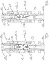
- Figures 1 and 2 each show a cross-sectional view of a functional element 10 of a xDSL distribution unit.
- the respective functional element 10 comprises a housing 11 accommodating at least three contact elements 12.
- the contact elements 12 are provided by contact springs.
- Each respective functional element 10 has a cutting contact 12a provided by an IDC contact. Through the cutting contacts 12a wires can be connect to the contact elements 12 of the respective contact element.
- the respective functional element 10 has a first contact element 12.1 to which a wire carrying a voice signal can be connected. Said first contact element 12.1 is also called V contact element.
- the respective functional element 10 has further a second contact element 12.2 to which a wire carrying a data signal can be connected. Said second contact element 12.2 is also called D contact element.
- the respective functional element 10 has further a third contact element 12.3 to which a wire carrying a line signal being a combined voice and data signal can be connected. Said third contact element 12.3 is also called L contact element.
- the functional element 10 of Figure 1 comprises in addition a fourth contact element 12.4 being not in use.
- the functional element 10 of Figure 2 merely comprises the above three contact elements 12.1, 12.2 and 12.3.
- the first contact element 12.1 - meaning the V contact element - and the third contact element 12.3 - meaning the L contact element - of the functional element 10 are both provided at a first side or front side of the functional element 10.
- the IDC contact 12a of the first and third contact elements 12.1 and 12.3 are accessible at said first side or front side of the functional element 10.
- At least the second contact element 12.2 - meaning the D contact element - and eventually the not used fourth contact element 12.4 of the functional element is/are provided at an opposite second side or back side of the functional element 10.
- the IDC contact 12a of the second contact element 12.2 is accessible at said second side or back side of the functional element 12.
- Figure 3 shows a very schematic equivalent circuit diagram of the functional element 10 of Figure 1 .
- a xDSL splitter 13 is plugged into such a functional element 10 (see Figure 4 ).
- the xDSL splitter 13 is plugged between the contact elements 12 of the functional element 10, namely from the second side or back side of the functional element 10 at which the second contact element 12.2 - meaning the D contact element - is accessible.
- the functional element 10 provides a xDSL service to a respective customer to which the functional element 10 is assigned.
- the invention provides a testing device 14 for a xDSL distribution unit of a telecommunication system.
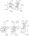
- Figures 8 and 9 show a top and bottom view of the testing device 14.
- Figure 10 shows a very schematic equivalent circuit diagram of the testing device 14.
- Figures 5, 6 and 7 show the testing device 14 plugged into a functional element 10 with the xDSL splitter 13 being removed or pulled out of the respective functional element 10.
- Figures 5, 6 and 7 the orientation of the testing device 14 relative to the functional element 10 and the side from which the testing device 14 is plugged into the functional element 10 is different.
- the testing device is used for testing communication lines of the telecommunication system.
- the testing device 14 comprises a contact tongue section 15 through which the testing device 14 can be plugged into the respective functional element 10.
- the testing device 14 comprises further a handle section 16 carrying the contact tongue section 15, wherein the testing device 14 can be plugged into the respective functional element 10 and pulled out of the respective functional element 10 through the handle section 16.
- the contact tongue section 15 of the testing device 14 has at a first side or upper side with four contact sections A1, A2, A3, A4, and further has at a second side or lower side two contact sections B1, B2.
- a first contact section A1 and a third contact section A3 provided at the first side or upper side of the contact tongue section 15 are both electrically connected to a fifth contact section B1 provided at the second side or lower side of the contact tongue section 15.
- a second contact section A2 and a fourth contact section A4 provided at the first side or upper side of the contact tongue section 15 are both electrically connected to a sixth contact section B2 provided at the second side or lower side of the contact tongue section 15.
- the testing device 14 When the testing device 14 is plugged into the functional element 10 of the xDSL distribution unit from the first side of the functional element 10 in a first orientation of the testing device 14 (see Figure 5 ), the testing device 14 electrically connects the first contact element 12.1 and second contact element 12.2 - meaning the V contact element and the D contact element - of the functional element 10.
- testing device 14 When the testing device 14 is plugged into the functional element 10 of the xDSL distribution unit from the first side of the functional element 10 in a second orientation of the testing device 14 (see Figure 6 , testing device turned by 180° compared to Figure 5 ), the testing device 14 electrically connects the second contact element 12.2 and third contact element 12.3 - meaning the D contact element and the L contact element - of the functional element 10.
- the testing device 14 When the testing device 14 is plugged into the functional element 10 of the xDSL distribution unit from the second side of the functional element 10 in a third orientation of the testing device 14 (see Figure 7 ), the testing device 14 electrically connects the first, second and third contact elements 12.1, 12.2 and 12.3 - meaning the V contact element and the D contact element and the L contact element - of the functional element 10.
- testing device 14 When the testing device 14 is plugged into the functional element 10 of the xDSL distribution unit from the second side of the functional element 10 in a fourth orientation of the testing device (not shown, testing device turned by 180° compared to Figure 7 ), the testing device 14 electrically connects the first contact element 12.1 and third contact element 12.3 - meaning the V contact element and the L contact element - of the functional element 10.
- the contact tongue section 15 has two contact tongues 17, 18 being separated by a slot 19.
- the slot 19 is optional.
- the two contact tongues 17, 18 can be provided by one single circuit board as long as the contact section are electrically isolated.
- a first contact tongue 17 provides at a first side or upper side the first and the third contact section A1, A3 and at a second side or lower side the fifth contact section B1. As mentioned above, the first contact section A1 and the third contact section A3 are both electrically connected to the fifth contact section B1.
- a second contact tongue 18 provides at a first side or upper side the second and the fourth contact section A2, A4 and at a second side or lower side the sixth contact section B2. As mentioned above, the second contact section A2 and the fourth contact section A4 are both electrically connected to the sixth contact section B2.
- the testing device 14 connects through different contact elements 12 of the respective functional element 10. So, different communication lines of the telecommunication system can be tested.
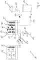
- the testing device 14 is preferably used to test communication lines of the telecommunication system 20 as shown in Figure 11 .
- the telecommunication system 20 provides xDSL services to different customers 21.
- a line signal L having a combined data signal D and voice signal V is provided the respective customer 21 through a wire or cable 22.
- Said wire or cable 22 is connected to a port 23 at the respective customer 21 and to a functional element of the MDF block I provided in a so-called passive cabinet 24.
- the line signal L is a combined data signal D and voice signal V.
- the data signal D is provided from a so-called DSLAM 25 provided at so-called active cabinet 26 through cables or wires 27 to the so-called passive cabinet 24. Said wires or cables 27 ate connected to a functional element of a MDF block III at the active cabinet 26 and to a functional element of the xDSL distribution block IV provided in the passive cabinet 24.
- the voice signal V is provided from a so-called central office 28 through a wire or cable 29. Said wire or cable 29 is connected to a port (not shown) at the central office 28 and to a functional element of the MDF block II provided in the passive cabinet 24. At the functional elements of the xDSL distribution blocks IV the data signals D and the vice signals V are combined to the line signal L though a xDSL splitter 13 plugged into a respective functional element 10 of the xDSL distribution blocks IV.
- a xDSL splitter 13 is removed from or pulled out of a respective functional element 10 of a respective xDSL distribution block IV.
- a testing device 14 is plugged into the respective functional element 10 from which the xDSL splitter 13 has been removed, namely from a defined side of the respective functional element 10 in a defined orientation of the testing device 14 (see Figures 5, 6 and 7 ).
- testing device 14 When the testing device 14 is plugged into the functional element 10 of the xDSL distribution block IV from the first side of the functional element 10 in a first orientation of the testing device 14 (see Figure 5 ), then the testing device 14 electrically connects the first contact element 12.1 and second contact element 12.2 - meaning the V contact element and the D contact element - of the functional element 10. In this situation it is possible to test a connection line extending from the MDF block III within the active cabinet 26 to the MDF block II within the passive cabinet 26.
- testing device 14 When the testing device 14 is plugged into the functional element 10 of the xDSL distribution block IV from the first side of the functional element 10 in the second orientation of the testing device 14 (see Figure 6 ), then the testing device 14 electrically connects the second element 12.2 and third contact element 12.3 - meaning the D contact element and the L contact element - of the functional element 10. In this situation it is possible to test a connection line extending from the MDF block III within the active cabinet 26 to the MDF block I within the passive cabinet 26.
- the testing device 14 When the testing device 14 is plugged into the functional element 10 of the xDSL distribution unit IV from the second side of the functional element 10 in the third orientation of the testing device 14 (see Figure 7 ), then the testing device 14 electrically connects the first, second and third contact elements 12.1, 12.2 and 12.3 - meaning the V contact element and the D contact element and the L contact element - of the functional element 10. In this situation it is possible to test the connection lines extending from the MDF block III within the active cabinet 26 to the MDF block II within the passive cabinet 26 and from the MDF block III within the active cabinet 26 to the MDF block I within the passive cabinet 26.
Landscapes
- Engineering & Computer Science (AREA)
- Signal Processing (AREA)
- Computer Networks & Wireless Communication (AREA)
- Connections Arranged To Contact A Plurality Of Conductors (AREA)
- Structure Of Telephone Exchanges (AREA)
Claims (8)
- Testvorrichtung (14) für eine xDSL-Verteilungseinheit eines Telekommunikationssystems,wobei die Testvorrichtung (14) konfiguriert ist, in ein Funktionselement (10) der xDSL-Verteilungseinheit eingesteckt zu werden,wobei die Testvorrichtung (14) einen Kontaktzungenabschnitt (15) umfasst, durch den die Testvorrichtung (14) in das Funktionselement (10) eingesteckt werden kann,wobei das Funktionselement (10) der xDSL-Verteilungseinheit mindestens drei Kontaktelemente (12.1, 12.2, 12.3) mit schneidenden Kontakten (12a) besitzt, die konfiguriert sind, einen Draht mit dem jeweiligen Kontaktelement (12) zu verbinden, nämlich dem ersten Kontaktelement (12.1), mit dem ein Draht, der ein Sprachsignal überträgt, verbunden werden kann, dem zweiten Kontaktelement (12.2), mit dem ein Draht, der ein Datensignal überträgt, verbunden werden kann, und dem dritten Kontaktelement (12.3), mit dem ein Draht, der ein Leitungssignal überträgt, das ein vereinigtes Sprach- und Datensignal ist, verbunden werden kann,wobei der Kontaktzungenabschnitt (15) auf einer ersten Seite oder oberen Seite des Kontaktzungenabschnitts (15) vier Kontaktabschnitte (A1, A2, A3, A4) und auf einer zweiten Seite oder unteren Seite des Kontaktzungenabschnitts (15) zwei Kontaktabschnitte (B1, B2) besitzt,wobei ein erster und ein dritter Kontaktabschnitt (A1, A3), die auf der ersten Seite oder der oberen Seite des Kontaktzungenabschnitts vorgesehen sind, beide mit einem fünften Kontaktabschnitt (B1), der auf der zweiten Seite oder der unteren Seite des Kontaktzungenabschnitts vorgesehen ist, elektrisch verbunden sind,wobei ein zweiter und ein vierter Kontaktabschnitt (A2, A4), die auf der ersten Seite oder der oberen Seite des Kontaktzungenabschnitts vorgesehen sind, beide mit einem sechsten Kontaktabschnitt (B2), der auf der zweiten Seite oder der unteren Seite des Kontaktzungenabschnitts vorgesehen ist, elektrisch verbunden sind,wobei dann, wenn die Testvorrichtung (14) in das Funktionselement der xDSL-Verteilungseinheit von einer ersten Seite des Funktionselements in einer ersten Orientierung der Testvorrichtung (14) eingesteckt wird, die Testvorrichtung das erste und das zweite Kontaktelement (12.1, 12.2) des Funktionselements (10) elektrisch verbindet,wobei dann, wenn die Testvorrichtung (14) in das Funktionselement der xDSL-Verteilungseinheit von der ersten Seite des Funktionselements in einer zweiten Orientierung der Testvorrichtung (14) eingesteckt wird, die Testvorrichtung das zweite und das dritte Kontaktelement (12.2, 12.3) des Funktionselements (10) elektrisch verbindet.
- Testvorrichtung nach Anspruch 1, dadurch gekennzeichnet, dass
dann, wenn die Testvorrichtung (14) in das Funktionselement der xDSL-Verteilungseinheit von einer zweiten Seite des Funktionselements in einer dritten Orientierung der Testvorrichtung (14) eingesteckt wird, die Testvorrichtung das erste, das zweite und das dritte Kontaktelement (12.1, 12.2, 12.3) des Funktionselements (10) elektrisch verbindet. - Testvorrichtung nach Anspruch 2, dadurch gekennzeichnet, dass
dann, wenn die Testvorrichtung (14) in das Funktionselement der xDSL-Verteilungseinheit von der zweiten Seite des Funktionselements (10) in einer vierten Orientierung der Testvorrichtung (14) eingesteckt wird, die Testvorrichtung das erste und das dritte des Funktionselements elektrisch verbindet. - Testvorrichtung nach einem der Ansprüche 1 bis 3, dadurch gekennzeichnet, dassdas erste Kontaktelement (12.1) und das dritte Kontaktelement (12.3) des Funktionselements beide auf einer ersten Seite oder Vorderseite des Funktionselements (10) vorgesehen sind,wobei das zweite Kontaktelement (12.2) des Funktionselements (10) auf einer zweiten Seite oder Rückseite des Funktionselements vorgesehen ist,wobei dann, wenn die Testvorrichtung (14) in das Funktionselement von der ersten Seite des Funktionselements (10) in einer ersten Orientierung eingesteckt wird, die Testvorrichtung das erste und das zweite Kontaktelement elektrisch verbindet,wobei dann, wenn die Testvorrichtung (14) in das Funktionselement (10) von der ersten Seite des Funktionselements in der zweiten Orientierung eingesteckt wird, die Testvorrichtung das zweite und das dritte Kontaktelement elektrisch verbindet,wobei dann, wenn die Testvorrichtung (14) in das Funktionselement (10) von der zweiten Seite des Funktionselements in der dritten Orientierung eingesteckt wird, die Testvorrichtung das erste, das zweite und das dritte Kontaktelement elektrisch verbindet.
- Testvorrichtung nach einem der Ansprüche 1 bis 4, dadurch gekennzeichnet, dassder Kontaktzungenabschnitt (15) zwei Kontaktzungen (17, 18) besitzt, die durch einen Schlitz (19) getrennt sind,wobei eine erste Kontaktzunge (17) auf einer ersten Seite oder oberen Seite den ersten und den dritten Kontaktabschnitt (A1, A3) und auf einer zweiten Seite oder unteren Seite den fünften Kontaktabschnitt (B1) bereitstellt,wobei eine zweite Kontaktzunge (18) auf einer ersten Seite oder oberen Seite den zweiten und den vierten Kontaktabschnitt (A2, A4) und auf einer zweiten Seite oder unteren Seite den sechsten Kontaktabschnitt (B2) bereitstellt.
- Testvorrichtung nach einem der Ansprüche 1 bis 5, dadurch gekennzeichnet, dass
die Testvorrichtung (14) einen Griffabschnitt (16) umfasst, der den Kontaktzungenabschnitt (15) trägt, wobei die Testvorrichtung (14) durch den Griffabschnitt (16) in ein Funktionselement (10) eingesteckt und aus einem Funktionselement (10) herausgezogen werden kann. - Telekommunikationssystem (20), das Folgendes umfasst:eine xDSL-Verteilungseinheit (IV),wobei die xDSL-Verteilungseinheit (IV) mehrere Funktionselemente besitzt, wobei jedes Funktionselement (10) mindestens drei Kontaktelemente (12.1, 12.2, 12.3) mit schneidenden Kontakten (12a) besitzt, die konfiguriert sind, einen Draht mit dem jeweiligen Kontaktelement zu verbinden, nämlicheinem erstem Kontaktelement (12.1), mit dem einem Draht, der ein Sprachsignal überträgt, verbunden werden kann,einem zweiten Kontaktelement (12.2), mit dem ein Draht, der ein Datensignal überträgt, verbunden werden kann, undeinem dritten Kontaktelement (12.3), mit dem ein Draht, der ein Leitungssignal überträgt, das ein vereinigtes Sprach- und Datensignal ist, verbunden werden kann,wobei die xDSL-Verteilungseinheit (IV) mehrere xDSL-Splitter (13) besitzt, wobei jeder xDSL-Splitter (13) in ein jeweiliges Funktionselement (10) eingefügt ist,mindestens eine Testvorrichtung (14) nach einem der Ansprüche 1 bis 6, wobei die jeweilige Testvorrichtung (14) in ein jeweiliges Funktionselement (10) eingefügt werden kann, wenn der jeweilige xDSL-Splitter (13) entfernt wurde.
- Verfahren zum Testen eines Telekommunikationssystems (20) nach Anspruch 7, wobei das Verfahren die folgenden Schritte umfasst:Entfernen eines jeweiligen xDSL-Splitters (13) von einem jeweiligen Funktionselement (10) der xDSL-Verteilungseinheit (IV),Einstecken einer Testvorrichtung (14) in ein jeweiliges Funktionselement (10), von dem der xDSL-Splitter (13) entfernt wurde, von einer definierten Seite des jeweiligen Funktionselements (10) in einer definierten Orientierung der Testvorrichtung (14),Messen elektrischer Spannungen und/oder elektrischer Ströme, die über das jeweilige Funktionselement (10) strömen, wobei die Testvorrichtung in das jeweilige Funktionselement (10) eingesteckt ist.
Priority Applications (1)
| Application Number | Priority Date | Filing Date | Title |
|---|---|---|---|
| EP19166144.6A EP3716596B1 (de) | 2019-03-29 | 2019-03-29 | Prüfvorrichtung für eine xdsl-verteilungseinheit eines telekommunikationssystems, telekommunikationssystem und verfahren zur prüfung davon |
Applications Claiming Priority (1)
| Application Number | Priority Date | Filing Date | Title |
|---|---|---|---|
| EP19166144.6A EP3716596B1 (de) | 2019-03-29 | 2019-03-29 | Prüfvorrichtung für eine xdsl-verteilungseinheit eines telekommunikationssystems, telekommunikationssystem und verfahren zur prüfung davon |
Publications (2)
| Publication Number | Publication Date |
|---|---|
| EP3716596A1 EP3716596A1 (de) | 2020-09-30 |
| EP3716596B1 true EP3716596B1 (de) | 2022-01-05 |
Family
ID=66041192
Family Applications (1)
| Application Number | Title | Priority Date | Filing Date |
|---|---|---|---|
| EP19166144.6A Not-in-force EP3716596B1 (de) | 2019-03-29 | 2019-03-29 | Prüfvorrichtung für eine xdsl-verteilungseinheit eines telekommunikationssystems, telekommunikationssystem und verfahren zur prüfung davon |
Country Status (1)
| Country | Link |
|---|---|
| EP (1) | EP3716596B1 (de) |
Family Cites Families (4)
| Publication number | Priority date | Publication date | Assignee | Title |
|---|---|---|---|---|
| US5199878A (en) * | 1990-11-15 | 1993-04-06 | Adc Telecommunications, Inc. | Plug-in jack card for normally closed contacts |
| US6831930B1 (en) | 2000-11-06 | 2004-12-14 | Adc Telecommunications, Inc. | Access panel for network end linesharing ADSL/POTS splitter applications |
| DE202007014702U1 (de) | 2007-10-18 | 2007-12-27 | Ccs Technology Inc., Wilmington | Verteilereinrichtung einer Telekommunikationsanlage sowie Stecker für eine Verteilereinrichtung einer Telekommunikationsanlage |
| EP2553939B1 (de) * | 2010-03-30 | 2016-10-12 | 3M Innovative Properties Company | Telekommunikationsmodul mit trennfunktion |
-
2019
- 2019-03-29 EP EP19166144.6A patent/EP3716596B1/de not_active Not-in-force
Also Published As
| Publication number | Publication date |
|---|---|
| EP3716596A1 (de) | 2020-09-30 |
Similar Documents
| Publication | Publication Date | Title |
|---|---|---|
| JP2004528758A (ja) | 端子ブロック及び分配点 | |
| NO326373B1 (no) | Fordelermodul for bruk i telekommunikasjons- og datasystemteknikk | |
| US7059864B2 (en) | Distribution device of a telecommunications system | |
| CN101427614B (zh) | 触点排,测量装置,配有其的电信模块及电信组件 | |
| US7625249B2 (en) | Quad field data distribution system with fiber optic converter | |
| EP3716596A1 (de) | Prüfvorrichtung für eine xdsl-verteilungseinheit eines telekommunikationssystems, telekommunikationssystem und verfahren zur prüfung davon | |
| US7207818B1 (en) | Telecommunications assembly including at least one telecommunications module | |
| US7625248B2 (en) | Field data distribution system with fiber optic converter | |
| CN1934876B (zh) | 一种组件和其中使用的电信模块 | |
| US7961846B2 (en) | Interface device for testing a telecommunication circuit | |
| KR100780162B1 (ko) | Xdsl 접속용 금속 테스트 액세스 | |
| JP2007505593A (ja) | ネットワーク接続検出組立体 | |
| CN101065978B (zh) | 电信模块,电信模块和至少一个分离器电路的组合,以及至少两个电信模块的组件 | |
| JP2002232922A (ja) | Adsl用スプリッタ装置及び配線方法 | |
| CN1934877B (zh) | 电信领域中的模块配置 | |
| US20020084787A1 (en) | Self powered DSL port continuity checker | |
| CA1175171A (en) | Testing facility for telephone conference bridge | |
| US9001995B2 (en) | Telecommunications module with disconnection feature | |
| US20050018818A1 (en) | Connection architecture for xdsl networks and intermediate distribution frame required by said architecture | |
| US20040253878A1 (en) | Patch panel providing 64-pin connectors | |
| CN101554061A (zh) | 电信领域中的配线点中的开关模块以及包括该开关模块的组件和使用该开关模块的方法 | |
| WO2006022865A1 (en) | Termination module including subscriber bridge having burglar alarm connections | |
| MXPA06010517A (en) | Modular arrangement in the field of telecommunications | |
| CN101351927A (zh) | 包括至少一个通信模块,测试总线和部件套件的通信组件 | |
| CA2621878A1 (en) | Field data distribution system with fiber optic converter |
Legal Events
| Date | Code | Title | Description |
|---|---|---|---|
| PUAI | Public reference made under article 153(3) epc to a published international application that has entered the european phase |
Free format text: ORIGINAL CODE: 0009012 |
|
| STAA | Information on the status of an ep patent application or granted ep patent |
Free format text: STATUS: THE APPLICATION HAS BEEN PUBLISHED |
|
| AK | Designated contracting states |
Kind code of ref document: A1 Designated state(s): AL AT BE BG CH CY CZ DE DK EE ES FI FR GB GR HR HU IE IS IT LI LT LU LV MC MK MT NL NO PL PT RO RS SE SI SK SM TR |
|
| AX | Request for extension of the european patent |
Extension state: BA ME |
|
| STAA | Information on the status of an ep patent application or granted ep patent |
Free format text: STATUS: REQUEST FOR EXAMINATION WAS MADE |
|
| REG | Reference to a national code |
Ref country code: DE Ref legal event code: R079 Ref document number: 602019010561 Country of ref document: DE Free format text: PREVIOUS MAIN CLASS: H04M0003000000 Ipc: H04M0003260000 |
|
| 17P | Request for examination filed |
Effective date: 20210330 |
|
| RBV | Designated contracting states (corrected) |
Designated state(s): AL AT BE BG CH CY CZ DE DK EE ES FI FR GB GR HR HU IE IS IT LI LT LU LV MC MK MT NL NO PL PT RO RS SE SI SK SM TR |
|
| GRAP | Despatch of communication of intention to grant a patent |
Free format text: ORIGINAL CODE: EPIDOSNIGR1 |
|
| STAA | Information on the status of an ep patent application or granted ep patent |
Free format text: STATUS: GRANT OF PATENT IS INTENDED |
|
| RIC1 | Information provided on ipc code assigned before grant |
Ipc: H04M 3/26 20060101AFI20210429BHEP Ipc: H04M 3/00 20060101ALI20210429BHEP Ipc: H04Q 1/14 20060101ALI20210429BHEP |
|
| INTG | Intention to grant announced |
Effective date: 20210527 |
|
| RIN1 | Information on inventor provided before grant (corrected) |
Inventor name: FASCE, XAVIER Inventor name: HAJOK, JOHANN Inventor name: LUTTERKORDT, ULRICH Inventor name: OTTO, HANS DIETER |
|
| GRAJ | Information related to disapproval of communication of intention to grant by the applicant or resumption of examination proceedings by the epo deleted |
Free format text: ORIGINAL CODE: EPIDOSDIGR1 |
|
| STAA | Information on the status of an ep patent application or granted ep patent |
Free format text: STATUS: REQUEST FOR EXAMINATION WAS MADE |
|
| GRAS | Grant fee paid |
Free format text: ORIGINAL CODE: EPIDOSNIGR3 |
|
| STAA | Information on the status of an ep patent application or granted ep patent |
Free format text: STATUS: GRANT OF PATENT IS INTENDED |
|
| GRAP | Despatch of communication of intention to grant a patent |
Free format text: ORIGINAL CODE: EPIDOSNIGR1 |
|
| INTC | Intention to grant announced (deleted) | ||
| GRAA | (expected) grant |
Free format text: ORIGINAL CODE: 0009210 |
|
| STAA | Information on the status of an ep patent application or granted ep patent |
Free format text: STATUS: THE PATENT HAS BEEN GRANTED |
|
| INTG | Intention to grant announced |
Effective date: 20211109 |
|
| AK | Designated contracting states |
Kind code of ref document: B1 Designated state(s): AL AT BE BG CH CY CZ DE DK EE ES FI FR GB GR HR HU IE IS IT LI LT LU LV MC MK MT NL NO PL PT RO RS SE SI SK SM TR |
|
| REG | Reference to a national code |
Ref country code: GB Ref legal event code: FG4D |
|
| REG | Reference to a national code |
Ref country code: CH Ref legal event code: EP |
|
| REG | Reference to a national code |
Ref country code: AT Ref legal event code: REF Ref document number: 1461610 Country of ref document: AT Kind code of ref document: T Effective date: 20220115 |
|
| REG | Reference to a national code |
Ref country code: DE Ref legal event code: R096 Ref document number: 602019010561 Country of ref document: DE |
|
| REG | Reference to a national code |
Ref country code: IE Ref legal event code: FG4D |
|
| REG | Reference to a national code |
Ref country code: LT Ref legal event code: MG9D |
|
| PGFP | Annual fee paid to national office [announced via postgrant information from national office to epo] |
Ref country code: DE Payment date: 20220127 Year of fee payment: 4 |
|
| REG | Reference to a national code |
Ref country code: NL Ref legal event code: MP Effective date: 20220105 |
|
| REG | Reference to a national code |
Ref country code: AT Ref legal event code: MK05 Ref document number: 1461610 Country of ref document: AT Kind code of ref document: T Effective date: 20220105 |
|
| PG25 | Lapsed in a contracting state [announced via postgrant information from national office to epo] |
Ref country code: NL Free format text: LAPSE BECAUSE OF FAILURE TO SUBMIT A TRANSLATION OF THE DESCRIPTION OR TO PAY THE FEE WITHIN THE PRESCRIBED TIME-LIMIT Effective date: 20220105 |
|
| PG25 | Lapsed in a contracting state [announced via postgrant information from national office to epo] |
Ref country code: SE Free format text: LAPSE BECAUSE OF FAILURE TO SUBMIT A TRANSLATION OF THE DESCRIPTION OR TO PAY THE FEE WITHIN THE PRESCRIBED TIME-LIMIT Effective date: 20220105 Ref country code: RS Free format text: LAPSE BECAUSE OF FAILURE TO SUBMIT A TRANSLATION OF THE DESCRIPTION OR TO PAY THE FEE WITHIN THE PRESCRIBED TIME-LIMIT Effective date: 20220105 Ref country code: PT Free format text: LAPSE BECAUSE OF FAILURE TO SUBMIT A TRANSLATION OF THE DESCRIPTION OR TO PAY THE FEE WITHIN THE PRESCRIBED TIME-LIMIT Effective date: 20220505 Ref country code: NO Free format text: LAPSE BECAUSE OF FAILURE TO SUBMIT A TRANSLATION OF THE DESCRIPTION OR TO PAY THE FEE WITHIN THE PRESCRIBED TIME-LIMIT Effective date: 20220405 Ref country code: LT Free format text: LAPSE BECAUSE OF FAILURE TO SUBMIT A TRANSLATION OF THE DESCRIPTION OR TO PAY THE FEE WITHIN THE PRESCRIBED TIME-LIMIT Effective date: 20220105 Ref country code: HR Free format text: LAPSE BECAUSE OF FAILURE TO SUBMIT A TRANSLATION OF THE DESCRIPTION OR TO PAY THE FEE WITHIN THE PRESCRIBED TIME-LIMIT Effective date: 20220105 Ref country code: ES Free format text: LAPSE BECAUSE OF FAILURE TO SUBMIT A TRANSLATION OF THE DESCRIPTION OR TO PAY THE FEE WITHIN THE PRESCRIBED TIME-LIMIT Effective date: 20220105 Ref country code: BG Free format text: LAPSE BECAUSE OF FAILURE TO SUBMIT A TRANSLATION OF THE DESCRIPTION OR TO PAY THE FEE WITHIN THE PRESCRIBED TIME-LIMIT Effective date: 20220405 |
|
| PG25 | Lapsed in a contracting state [announced via postgrant information from national office to epo] |
Ref country code: PL Free format text: LAPSE BECAUSE OF FAILURE TO SUBMIT A TRANSLATION OF THE DESCRIPTION OR TO PAY THE FEE WITHIN THE PRESCRIBED TIME-LIMIT Effective date: 20220105 Ref country code: LV Free format text: LAPSE BECAUSE OF FAILURE TO SUBMIT A TRANSLATION OF THE DESCRIPTION OR TO PAY THE FEE WITHIN THE PRESCRIBED TIME-LIMIT Effective date: 20220105 Ref country code: GR Free format text: LAPSE BECAUSE OF FAILURE TO SUBMIT A TRANSLATION OF THE DESCRIPTION OR TO PAY THE FEE WITHIN THE PRESCRIBED TIME-LIMIT Effective date: 20220406 Ref country code: FI Free format text: LAPSE BECAUSE OF FAILURE TO SUBMIT A TRANSLATION OF THE DESCRIPTION OR TO PAY THE FEE WITHIN THE PRESCRIBED TIME-LIMIT Effective date: 20220105 Ref country code: AT Free format text: LAPSE BECAUSE OF FAILURE TO SUBMIT A TRANSLATION OF THE DESCRIPTION OR TO PAY THE FEE WITHIN THE PRESCRIBED TIME-LIMIT Effective date: 20220105 |
|
| PG25 | Lapsed in a contracting state [announced via postgrant information from national office to epo] |
Ref country code: IS Free format text: LAPSE BECAUSE OF FAILURE TO SUBMIT A TRANSLATION OF THE DESCRIPTION OR TO PAY THE FEE WITHIN THE PRESCRIBED TIME-LIMIT Effective date: 20220505 |
|
| REG | Reference to a national code |
Ref country code: DE Ref legal event code: R097 Ref document number: 602019010561 Country of ref document: DE |
|
| PG25 | Lapsed in a contracting state [announced via postgrant information from national office to epo] |
Ref country code: SM Free format text: LAPSE BECAUSE OF FAILURE TO SUBMIT A TRANSLATION OF THE DESCRIPTION OR TO PAY THE FEE WITHIN THE PRESCRIBED TIME-LIMIT Effective date: 20220105 Ref country code: SK Free format text: LAPSE BECAUSE OF FAILURE TO SUBMIT A TRANSLATION OF THE DESCRIPTION OR TO PAY THE FEE WITHIN THE PRESCRIBED TIME-LIMIT Effective date: 20220105 Ref country code: RO Free format text: LAPSE BECAUSE OF FAILURE TO SUBMIT A TRANSLATION OF THE DESCRIPTION OR TO PAY THE FEE WITHIN THE PRESCRIBED TIME-LIMIT Effective date: 20220105 Ref country code: MC Free format text: LAPSE BECAUSE OF FAILURE TO SUBMIT A TRANSLATION OF THE DESCRIPTION OR TO PAY THE FEE WITHIN THE PRESCRIBED TIME-LIMIT Effective date: 20220105 Ref country code: EE Free format text: LAPSE BECAUSE OF FAILURE TO SUBMIT A TRANSLATION OF THE DESCRIPTION OR TO PAY THE FEE WITHIN THE PRESCRIBED TIME-LIMIT Effective date: 20220105 Ref country code: DK Free format text: LAPSE BECAUSE OF FAILURE TO SUBMIT A TRANSLATION OF THE DESCRIPTION OR TO PAY THE FEE WITHIN THE PRESCRIBED TIME-LIMIT Effective date: 20220105 Ref country code: CZ Free format text: LAPSE BECAUSE OF FAILURE TO SUBMIT A TRANSLATION OF THE DESCRIPTION OR TO PAY THE FEE WITHIN THE PRESCRIBED TIME-LIMIT Effective date: 20220105 |
|
| REG | Reference to a national code |
Ref country code: CH Ref legal event code: PL |
|
| PLBE | No opposition filed within time limit |
Free format text: ORIGINAL CODE: 0009261 |
|
| STAA | Information on the status of an ep patent application or granted ep patent |
Free format text: STATUS: NO OPPOSITION FILED WITHIN TIME LIMIT |
|
| PG25 | Lapsed in a contracting state [announced via postgrant information from national office to epo] |
Ref country code: AL Free format text: LAPSE BECAUSE OF FAILURE TO SUBMIT A TRANSLATION OF THE DESCRIPTION OR TO PAY THE FEE WITHIN THE PRESCRIBED TIME-LIMIT Effective date: 20220105 |
|
| REG | Reference to a national code |
Ref country code: BE Ref legal event code: MM Effective date: 20220331 |
|
| 26N | No opposition filed |
Effective date: 20221006 |
|
| PG25 | Lapsed in a contracting state [announced via postgrant information from national office to epo] |
Ref country code: LU Free format text: LAPSE BECAUSE OF NON-PAYMENT OF DUE FEES Effective date: 20220329 Ref country code: LI Free format text: LAPSE BECAUSE OF NON-PAYMENT OF DUE FEES Effective date: 20220331 Ref country code: IE Free format text: LAPSE BECAUSE OF NON-PAYMENT OF DUE FEES Effective date: 20220329 Ref country code: FR Free format text: LAPSE BECAUSE OF NON-PAYMENT OF DUE FEES Effective date: 20220331 Ref country code: CH Free format text: LAPSE BECAUSE OF NON-PAYMENT OF DUE FEES Effective date: 20220331 |
|
| PG25 | Lapsed in a contracting state [announced via postgrant information from national office to epo] |
Ref country code: SI Free format text: LAPSE BECAUSE OF FAILURE TO SUBMIT A TRANSLATION OF THE DESCRIPTION OR TO PAY THE FEE WITHIN THE PRESCRIBED TIME-LIMIT Effective date: 20220105 Ref country code: BE Free format text: LAPSE BECAUSE OF NON-PAYMENT OF DUE FEES Effective date: 20220331 |
|
| PG25 | Lapsed in a contracting state [announced via postgrant information from national office to epo] |
Ref country code: IT Free format text: LAPSE BECAUSE OF FAILURE TO SUBMIT A TRANSLATION OF THE DESCRIPTION OR TO PAY THE FEE WITHIN THE PRESCRIBED TIME-LIMIT Effective date: 20220105 |
|
| REG | Reference to a national code |
Ref country code: DE Ref legal event code: R119 Ref document number: 602019010561 Country of ref document: DE |
|
| GBPC | Gb: european patent ceased through non-payment of renewal fee |
Effective date: 20230329 |
|
| PG25 | Lapsed in a contracting state [announced via postgrant information from national office to epo] |
Ref country code: GB Free format text: LAPSE BECAUSE OF NON-PAYMENT OF DUE FEES Effective date: 20230329 |
|
| PG25 | Lapsed in a contracting state [announced via postgrant information from national office to epo] |
Ref country code: GB Free format text: LAPSE BECAUSE OF NON-PAYMENT OF DUE FEES Effective date: 20230329 Ref country code: DE Free format text: LAPSE BECAUSE OF NON-PAYMENT OF DUE FEES Effective date: 20231003 |
|
| PG25 | Lapsed in a contracting state [announced via postgrant information from national office to epo] |
Ref country code: MK Free format text: LAPSE BECAUSE OF FAILURE TO SUBMIT A TRANSLATION OF THE DESCRIPTION OR TO PAY THE FEE WITHIN THE PRESCRIBED TIME-LIMIT Effective date: 20220105 Ref country code: CY Free format text: LAPSE BECAUSE OF FAILURE TO SUBMIT A TRANSLATION OF THE DESCRIPTION OR TO PAY THE FEE WITHIN THE PRESCRIBED TIME-LIMIT Effective date: 20220105 |
|
| PG25 | Lapsed in a contracting state [announced via postgrant information from national office to epo] |
Ref country code: HU Free format text: LAPSE BECAUSE OF FAILURE TO SUBMIT A TRANSLATION OF THE DESCRIPTION OR TO PAY THE FEE WITHIN THE PRESCRIBED TIME-LIMIT; INVALID AB INITIO Effective date: 20190329 |
|
| PG25 | Lapsed in a contracting state [announced via postgrant information from national office to epo] |
Ref country code: TR Free format text: LAPSE BECAUSE OF FAILURE TO SUBMIT A TRANSLATION OF THE DESCRIPTION OR TO PAY THE FEE WITHIN THE PRESCRIBED TIME-LIMIT Effective date: 20220105 |
|
| PG25 | Lapsed in a contracting state [announced via postgrant information from national office to epo] |
Ref country code: MT Free format text: LAPSE BECAUSE OF FAILURE TO SUBMIT A TRANSLATION OF THE DESCRIPTION OR TO PAY THE FEE WITHIN THE PRESCRIBED TIME-LIMIT Effective date: 20220105 |