EP3716713B1 - Kommunikationsverfahren, endgerätevorrichtung und netzwerkvorrichtung - Google Patents
Kommunikationsverfahren, endgerätevorrichtung und netzwerkvorrichtung Download PDFInfo
- Publication number
- EP3716713B1 EP3716713B1 EP19738308.6A EP19738308A EP3716713B1 EP 3716713 B1 EP3716713 B1 EP 3716713B1 EP 19738308 A EP19738308 A EP 19738308A EP 3716713 B1 EP3716713 B1 EP 3716713B1
- Authority
- EP
- European Patent Office
- Prior art keywords
- communications device
- time
- timer
- drx
- beam failure
- Prior art date
- Legal status (The legal status is an assumption and is not a legal conclusion. Google has not performed a legal analysis and makes no representation as to the accuracy of the status listed.)
- Active
Links
Images







Classifications
-
- H—ELECTRICITY
- H04—ELECTRIC COMMUNICATION TECHNIQUE
- H04W—WIRELESS COMMUNICATION NETWORKS
- H04W76/00—Connection management
- H04W76/10—Connection setup
- H04W76/19—Connection re-establishment
-
- H—ELECTRICITY
- H04—ELECTRIC COMMUNICATION TECHNIQUE
- H04L—TRANSMISSION OF DIGITAL INFORMATION, e.g. TELEGRAPHIC COMMUNICATION
- H04L1/00—Arrangements for detecting or preventing errors in the information received
- H04L1/12—Arrangements for detecting or preventing errors in the information received by using return channel
- H04L1/16—Arrangements for detecting or preventing errors in the information received by using return channel in which the return channel carries supervisory signals, e.g. repetition request signals
- H04L1/1607—Details of the supervisory signal
-
- H—ELECTRICITY
- H04—ELECTRIC COMMUNICATION TECHNIQUE
- H04L—TRANSMISSION OF DIGITAL INFORMATION, e.g. TELEGRAPHIC COMMUNICATION
- H04L1/00—Arrangements for detecting or preventing errors in the information received
- H04L1/12—Arrangements for detecting or preventing errors in the information received by using return channel
- H04L1/16—Arrangements for detecting or preventing errors in the information received by using return channel in which the return channel carries supervisory signals, e.g. repetition request signals
- H04L1/18—Automatic repetition systems, e.g. Van Duuren systems
- H04L1/1812—Hybrid protocols; Hybrid automatic repeat request [HARQ]
-
- H—ELECTRICITY
- H04—ELECTRIC COMMUNICATION TECHNIQUE
- H04L—TRANSMISSION OF DIGITAL INFORMATION, e.g. TELEGRAPHIC COMMUNICATION
- H04L1/00—Arrangements for detecting or preventing errors in the information received
- H04L1/12—Arrangements for detecting or preventing errors in the information received by using return channel
- H04L1/16—Arrangements for detecting or preventing errors in the information received by using return channel in which the return channel carries supervisory signals, e.g. repetition request signals
- H04L1/18—Automatic repetition systems, e.g. Van Duuren systems
- H04L1/1822—Automatic repetition systems, e.g. Van Duuren systems involving configuration of automatic repeat request [ARQ] with parallel processes
-
- H—ELECTRICITY
- H04—ELECTRIC COMMUNICATION TECHNIQUE
- H04L—TRANSMISSION OF DIGITAL INFORMATION, e.g. TELEGRAPHIC COMMUNICATION
- H04L1/00—Arrangements for detecting or preventing errors in the information received
- H04L1/12—Arrangements for detecting or preventing errors in the information received by using return channel
- H04L1/16—Arrangements for detecting or preventing errors in the information received by using return channel in which the return channel carries supervisory signals, e.g. repetition request signals
- H04L1/18—Automatic repetition systems, e.g. Van Duuren systems
- H04L1/1829—Arrangements specially adapted for the receiver end
- H04L1/1848—Time-out mechanisms
-
- H—ELECTRICITY
- H04—ELECTRIC COMMUNICATION TECHNIQUE
- H04L—TRANSMISSION OF DIGITAL INFORMATION, e.g. TELEGRAPHIC COMMUNICATION
- H04L1/00—Arrangements for detecting or preventing errors in the information received
- H04L1/12—Arrangements for detecting or preventing errors in the information received by using return channel
- H04L1/16—Arrangements for detecting or preventing errors in the information received by using return channel in which the return channel carries supervisory signals, e.g. repetition request signals
- H04L1/18—Automatic repetition systems, e.g. Van Duuren systems
- H04L1/1867—Arrangements specially adapted for the transmitter end
- H04L1/188—Time-out mechanisms
-
- H—ELECTRICITY
- H04—ELECTRIC COMMUNICATION TECHNIQUE
- H04L—TRANSMISSION OF DIGITAL INFORMATION, e.g. TELEGRAPHIC COMMUNICATION
- H04L1/00—Arrangements for detecting or preventing errors in the information received
- H04L1/12—Arrangements for detecting or preventing errors in the information received by using return channel
- H04L1/16—Arrangements for detecting or preventing errors in the information received by using return channel in which the return channel carries supervisory signals, e.g. repetition request signals
- H04L1/18—Automatic repetition systems, e.g. Van Duuren systems
- H04L1/1867—Arrangements specially adapted for the transmitter end
- H04L1/1887—Scheduling and prioritising arrangements
-
- H—ELECTRICITY
- H04—ELECTRIC COMMUNICATION TECHNIQUE
- H04L—TRANSMISSION OF DIGITAL INFORMATION, e.g. TELEGRAPHIC COMMUNICATION
- H04L1/00—Arrangements for detecting or preventing errors in the information received
- H04L1/12—Arrangements for detecting or preventing errors in the information received by using return channel
- H04L1/16—Arrangements for detecting or preventing errors in the information received by using return channel in which the return channel carries supervisory signals, e.g. repetition request signals
- H04L1/18—Automatic repetition systems, e.g. Van Duuren systems
- H04L1/1867—Arrangements specially adapted for the transmitter end
- H04L1/1896—ARQ related signaling
-
- H—ELECTRICITY
- H04—ELECTRIC COMMUNICATION TECHNIQUE
- H04W—WIRELESS COMMUNICATION NETWORKS
- H04W72/00—Local resource management
- H04W72/04—Wireless resource allocation
- H04W72/044—Wireless resource allocation based on the type of the allocated resource
- H04W72/046—Wireless resource allocation based on the type of the allocated resource the resource being in the space domain, e.g. beams
-
- H—ELECTRICITY
- H04—ELECTRIC COMMUNICATION TECHNIQUE
- H04W—WIRELESS COMMUNICATION NETWORKS
- H04W72/00—Local resource management
- H04W72/20—Control channels or signalling for resource management
- H04W72/21—Control channels or signalling for resource management in the uplink direction of a wireless link, i.e. towards the network
-
- H—ELECTRICITY
- H04—ELECTRIC COMMUNICATION TECHNIQUE
- H04W—WIRELESS COMMUNICATION NETWORKS
- H04W72/00—Local resource management
- H04W72/20—Control channels or signalling for resource management
- H04W72/23—Control channels or signalling for resource management in the downlink direction of a wireless link, i.e. towards a terminal
-
- H—ELECTRICITY
- H04—ELECTRIC COMMUNICATION TECHNIQUE
- H04W—WIRELESS COMMUNICATION NETWORKS
- H04W76/00—Connection management
- H04W76/20—Manipulation of established connections
- H04W76/28—Discontinuous transmission [DTX]; Discontinuous reception [DRX]
-
- H—ELECTRICITY
- H04—ELECTRIC COMMUNICATION TECHNIQUE
- H04W—WIRELESS COMMUNICATION NETWORKS
- H04W28/00—Network traffic management; Network resource management
- H04W28/02—Traffic management, e.g. flow control or congestion control
- H04W28/04—Error control
-
- Y—GENERAL TAGGING OF NEW TECHNOLOGICAL DEVELOPMENTS; GENERAL TAGGING OF CROSS-SECTIONAL TECHNOLOGIES SPANNING OVER SEVERAL SECTIONS OF THE IPC; TECHNICAL SUBJECTS COVERED BY FORMER USPC CROSS-REFERENCE ART COLLECTIONS [XRACs] AND DIGESTS
- Y02—TECHNOLOGIES OR APPLICATIONS FOR MITIGATION OR ADAPTATION AGAINST CLIMATE CHANGE
- Y02D—CLIMATE CHANGE MITIGATION TECHNOLOGIES IN INFORMATION AND COMMUNICATION TECHNOLOGIES [ICT], I.E. INFORMATION AND COMMUNICATION TECHNOLOGIES AIMING AT THE REDUCTION OF THEIR OWN ENERGY USE
- Y02D30/00—Reducing energy consumption in communication networks
- Y02D30/70—Reducing energy consumption in communication networks in wireless communication networks
Definitions
- This application relates to communications technologies, and in particular, to communication methods, a communications device, and a network device.
- a discontinuous reception (Discontinuous Reception, DRX) mechanism is introduced.
- the DRX mechanism indicates that when there is no data transmission, the terminal device turns off a receiver in a time period to reduce the power consumption.
- a basic DRX mechanism is to configure a DRX cycle (cycle) for a terminal device in an RRC_CONNECTED state.
- the DRX cycle includes "On Duration” and "Opportunity for DRX".
- the "On Duration” is also referred to as an active period, and the "Opportunity for DRX” is also referred to as a sleep period.
- the terminal device monitors a physical downlink control channel (Physical Downlink Control Channel, PDCCH) and receives information on the PDCCH.
- PDCCH Physical Downlink Control Channel
- the terminal device does not receive the information on the PDCCH, so that the power consumption is reduced.
- the terminal device If the terminal device does not receive scheduling information on the PDCCH within the "On Duration” time, the terminal device enters the sleep period and stops receiving the information on the PDCCH. If the terminal device receives the scheduling information on the PDCCH within the "On Duration” time, the terminal device starts or re-starts a DRX-inactivity timer (DRX-inactivity Timer), and the terminal device monitors the PDCCH and remains in an active state within a timing time of the DRX-inactivity timer. The terminal device enters a sleep state when the DRX inactivity timer expires.
- DRX-inactivity Timer DRX-inactivity Timer
- the terminal device may need to receive a downlink data packet that is retransmitted, and therefore, the terminal device is still controlled by a DRX-retransmission timer (DRX-Retransmission Timer) after the terminal device enters the sleep state, and the terminal device maintains one DRX-retransmission timer for each hybrid automatic repeat request (Hybrid Automatic Repeat Request, HARQ) process.
- DRX-Retransmission Timer DRX-Retransmission Timer
- HARQ Hybrid Automatic Repeat Request
- a DRX mechanism is also introduced in a 5G system, and the DRX mechanism in the 5G system is similar to the DRX mechanism in the LTE system.
- some messages in the 5G system cannot be received, for example, a slot format indicator (Slot Format Indicator, SFI), a pre-emption indicator (Pre-emption indicator, INT) PDCCH, a beam recovery request response (beam recovery request response), a retransmission indication and retransmission scheduling during grant-free (grant-free) transmission.
- This application provides communication methods, a communications device, and a network device, so that when the communications device is configured with DRX, the communications device accurately receives data.
- the present invention is defined by the attached set of claims.
- a communication method includes: receiving, by a communications device, configuration information sent by a network device, where the configuration information includes a sending resource of the beam failure recovery request, and the sending resource is a physical uplink control channel PUCCH or a media access control control element MAC CE; when a beam failure occurs in a secondary cell of the communications device, sending, by the communications device, the beam failure recovery request to the network device by using the PUCCH or the MAC CE; and determining, by the communications device, an active state time of DRX based on a status of the beam failure recovery request.
- the method further includes: monitoring, by the communications device, a PDCCH within the active state time of the DRX.
- the configuration information includes a value of a response window timer
- the determining, by the communications device, an active state time of DRX based on a status of the beam failure recovery request includes: after the beam failure recovery request is sent, controlling, by the communications device, the response window timer to start, where a working time of the response window timer is the active state time of the DRX.
- the configuration information includes indication information of a first time, the first time is a time for which the communications device delays, after sending the beam failure recovery request, starting the response window timer, and the determining, by the communications device, an active state time of DRX based on a status of the beam failure recovery request includes: after the beam failure recovery request is sent, controlling, by the communications device, the response window timer to start after a delay of the first time, where a working time of the response window timer is the active state time of the DRX.
- the base station needs to process the beam failure recovery request process, and therefore, the communications device cannot receive the response message of the beam failure recovery request in the beam failure recovery request.
- the communications device starts the response window timer after the delay of the first time, so that it can be ensured that the communications device can accurately receive the response message of the beam failure recovery request, and the power consumption of the communications device is further reduced.
- the method further includes: when receiving a first indication, controlling, by the communications device, the response window timer to stop.
- the first time includes X symbols, and a value of X is greater than 0.
- the determining, by the communications device, an active state time of DRX based on a status of the beam failure recovery request includes: when the beam failure recovery request is suspended, determining, by the communications device, that a time in which the beam failure recovery request is in a suspended state is the active state time of the DRX.
- a communication method includes:
- the base station sends a response message of the beam failure recovery request to the terminal device within the active state time of the DRX of the terminal device.
- the configuration information further includes indication information of a first time, and the first time is a time for which the communications device delays, after sending the beam failure recovery request, starting the response window timer.
- the first time includes X symbols, and a value of X is greater than 0.
- a communication method includes: receiving, by a communications device, configuration information of a configured grant timer and configuration information of an uplink retransmission timer that are sent by a network device; determining, by the communications device, a stopping time of the uplink retransmission timer based on a running status of the configured grant timer, where discontinuous reception DRX of the communications device is in an active state when the uplink retransmission timer works; and monitoring, by the communications device, a physical downlink control channel PDCCH when the DRX of the communications device is in the active state.
- the determining, by the communications device, a stopping time of the uplink retransmission timer based on a running status of the configured grant timer includes: when the configured grant timer expires, if the uplink retransmission timer is working, controlling, by the communications device, the uplink retransmission timer to stop.
- the uplink retransmission timer is stopped in time, so that the power consumption of the terminal device can be further reduced.
- the configured grant timer is started by the communications device after the first sending of first data.
- the configured grant timer is started by the communications device when first data is sent.
- the configured grant timer is started by the communications device after an uplink round trip time timer expires.
- a communication method includes:
- the base station sends a retransmission indication during uplink grant-free transmission to the terminal device when the DRX of the terminal device is in the active state.
- a communication method includes:
- the determining, by the communications device, an active state time of DRX based on a running status of the configured grant timer includes: controlling, by the communications device after the first sending of first data, the configured grant timer to start, where the DRX is in the active state when the configured grant timer works.
- the method further includes: receiving, by the communications device, indication information that is of a first time and that is sent by the network device, where the first time is a time for which the communications device delays, after the first sending of first data, starting the configured grant timer, and the determining, by the communications device, an active state time of DRX based on a running status of the configured grant timer includes: controlling, by the communications device after the first sending of the first data, the configured grant timer to start after a delay of the first time, where the DRX is in the active state when the configured grant timer works.
- the controlling, by the communications device after the first sending of the first data, the configured grant timer to start after a delay of the first time includes:
- the active state of the DRX is determined by combining the configured grant timer and an existing uplink round trip time timer, so that implementation is flexible, and a change performed on a protocol of the communications device is small.
- the determining, by the communications device, an active state time of DRX based on a running status of the configured grant timer includes:
- the determining, by the communications device, an active state time of DRX based on a running status of the configured grant timer includes:
- the active state of the DRX is determined by combining the configured grant timer and an existing uplink round trip time timer and uplink retransmission timer, so that the implementation is flexible, and a change performed on a protocol of the communications device is small.
- the method further includes: when receiving a first indication, controlling, by the communications device, the configured grant timer to stop.
- a communication method includes:
- the network device sends a retransmission indication during uplink grant-free transmission to the communications device when the DRX of the communications device is in an active state.
- the method further includes: sending, by the network device, indication information of a first time to the communications device, where the first time is a time for which the communications device delays, after the first sending of first data, starting the configured grant timer.
- the indication information of the first time is configuration information of an uplink round trip time timer.
- the method further includes: sending, by the network device, the configuration information of the uplink round trip time timer to the communications device.
- a communication method includes:
- the communications device when the communications device is configured with the DRX, the communications device can accurately receive the slot format indicator SFI message or the downlink pre-emption indicator message.
- the method further includes: monitoring, by the communications device, a physical downlink control channel PDCCH within the active state time of the DRX.
- the determining, by the communications device, an active state time of DRX based on the monitoring cycle and a slot index includes:
- the method when the first message is the SFI, the method further includes:
- the communications device needs to monitor a PDCCH only in a specific slot, where the slot includes a flexible slot or a flexible symbol, so that power consumption of the terminal device is further reduced.
- the determining, by the communications device, an active state time of DRX based on the monitoring cycle and a slot index includes:
- a communication method includes:
- the network device sends the first message to the communications device when the DRX of the communications device is in an active state.
- the determining, by the network device, an active state time of DRX of the communications device based on the monitoring cycle and a slot index includes:
- the method when the first message is the SFI, the method further includes:
- the method when the first message is the downlink pre-emption indicator message, the method further includes:
- the network device sends an offset value to the communications device.
- a communication method includes:
- the network device indicates the retransmission manner used for the downlink transmission, so that the communications device is prevented from starting the downlink round trip time timer and the downlink retransmission timer when the grant-free transmission is used for the downlink transmission. Therefore, power consumption of the communications device is reduced and a resource waste is avoided.
- the controlling, by the communications device, running statuses of a downlink round trip time timer and a downlink retransmission timer based on the indication information includes:
- the controlling, by the communications device, running statuses of a downlink round trip time timer and a downlink retransmission timer based on the indication information includes: when the indication information indicates that the retransmission manner used for the downlink transmission is the grant-free transmission manner, controlling, by the communications device after the physical uplink control channel PUCCH transmission, the downlink round trip time timer and the downlink retransmission timer not to start.
- the downlink round trip time timer and the downlink retransmission timer are timers of a hybrid automatic repeat request HARQ process associated with downlink retransmitted data.
- a communication method includes: sending, by a network device, indication information to a communications device, where the indication information is used to indicate a retransmission manner used for downlink transmission, and the retransmission manner is a grant-based transmission or grant-free transmission manner.
- the network device sends retransmitted data to the communications device based on the retransmission manner used for the downlink transmission.
- the method further includes: sending, by the network device, configuration information of a downlink round trip time timer and configuration information of a downlink retransmission timer to the communications device.
- a communication method includes:
- the communications device can accurately receive retransmitted data when receiving data in a downlink grant-free transmission manner.
- the downlink data for the grant-free transmission received by the communications device is associated with a hybrid automatic repeat request HARQ process corresponding to the downlink retransmission timer.
- the downlink data for the grant-free transmission is first data for the first sending.
- a communication method includes: sending, by a network device, configuration information of a downlink round trip time timer and configuration information of a downlink retransmission timer to a communications device.
- the network device when the downlink retransmission timer runs, the network device sends downlink data for grant-free transmission to the communications device based on the configuration information of the downlink round trip time timer and the configuration information of the downlink retransmission timer.
- a communications device includes:
- the receiving module is further configured to monitor a physical downlink control channel PDCCH within the active state time of the DRX.
- the configuration information further includes a value of a response window timer
- the processing module is specifically configured to: after the beam failure recovery request is sent, control the response window timer to start, where a working time of the response window timer is the active state time of the DRX.
- the configuration information further includes indication information of a first time, the first time is a time for which the communications device delays, after sending the beam failure recovery request, starting the response window timer, and the processing module is specifically configured to: after the beam failure recovery request is sent, control the response window timer to start after a delay of the first time, where a working time of the response window timer is the active state time of the DRX.
- the receiving module is further configured to receive a first indication; and the processing module is further configured to: when the receiving module receives the first indication, control the response window timer to stop.
- the first time includes X symbols, and a value of X is greater than 0.
- the processing module when the sending module sends the beam failure recovery request by using the PUCCH, is specifically configured to: when the beam failure recovery request is suspended, determine that a time in which the beam failure recovery request is in a suspended state is the active state time of the DRX.
- a network device includes:
- the configuration information further includes indication information of a first time, and the first time is a time for which the communications device delays, after sending the beam failure recovery request, starting the response window timer.
- the first time includes X symbols, and a value of X is greater than 0.
- a communications device includes:
- the processing module is specifically configured to: when the configured grant timer expires, if the uplink retransmission timer is working, control the uplink retransmission timer to stop.
- the configured grant timer is started after the first sending of first data.
- the configured grant timer is started when first data is sent.
- the configured grant timer is started after an uplink round trip time timer expires.
- a network device includes:
- the processing module is further configured to: send a retransmission indication during uplink grant-free transmission to the terminal device when the DRX of the terminal device is in the active state.
- a communications device includes:
- the processing module is specifically configured to:
- the receiving module is further configured to receive indication information that is of a first time and that is sent by the network device, where the first time is a time for which the communications device delays, after the first sending of first data, starting the configured grant timer; and the processing module is specifically configured to: control, after the first sending of the first data, the configured grant timer to start after a delay of the first time, where the DRX is in the active state when the configured grant timer works.
- processing module controls, after the first sending of the first data, the configured grant timer to start after a delay of the first time includes:
- the processing module is specifically configured to:
- the processing module is specifically configured to:
- the processing module is specifically configured to: control, when the first data is sent, the configured grant timer to start; and control, after the first sending of the first data, the uplink round trip time timer of the hybrid automatic repeat request HARQ process for processing the first data to start, where after the uplink round trip time timer expires and when the configured grant timer works, the DRX is in the active state.
- the processing module is further configured to: when the receiving module receives a first indication, control the configured grant timer to stop.
- a network device includes:
- the sending module is further configured to send a retransmission indication during uplink grant-free transmission to the communications device when the DRX of the communications device is in an active state.
- the sending module is further configured to: send indication information of a first time to the communications device, where the first time is a time for which the communications device delays, after the first sending of first data, starting the configured grant timer.
- the indication information of the first time is configuration information of an uplink round trip time timer.
- the sending module is further configured to: send the configuration information of the uplink round trip time timer to the communications device.
- a communications device includes:
- the receiving module is further configured to: monitor a physical downlink control channel PDCCH within the active state time of the DRX.
- the processing module is specifically configured to:
- the receiving module is further configured to:
- the determining module is specifically configured to:
- a network device includes:
- the sending module is further configured to send the first message to the communications device when the DRX of the communications device is in an active state.
- the processing module is specifically configured to:
- the sending module is further configured to:
- the processing module is further configured to:
- the network device sends an offset value to the communications device.
- a communications device includes:
- the processing module is specifically configured to:
- the processing module is specifically configured to: when the indication information indicates that the retransmission manner used for the downlink transmission is the grant-free transmission manner, control, after the physical uplink control channel PUCCH transmission, the downlink round trip time timer and the downlink retransmission timer not to start.
- the downlink round trip time timer and the downlink retransmission timer are timers of a hybrid automatic repeat request HARQ process associated with downlink retransmitted data.
- a network device includes: a sending module, configured to send indication information to a communications device, where the indication information is used to indicate a retransmission manner used for downlink transmission, and the retransmission manner is a grant-based transmission or grant-free transmission manner.
- a communications device includes:
- the downlink data for the grant-free transmission received by the communications device is associated with a hybrid automatic repeat request HARQ process corresponding to the downlink retransmission timer.
- the downlink data for the grant-free transmission is first data for the first sending.
- a network device includes: a sending module, configured to send configuration information of a downlink round trip time timer and configuration information of a downlink retransmission timer to a communications device.
- the sending module when the downlink retransmission timer runs, is further configured to send downlink data for grant-free transmission to the communications device based on the configuration information of the downlink round trip time timer and the configuration information of the downlink retransmission timer.
- a communications device includes: a processor, a memory, and a transceiver, where the memory is configured to store an instruction, the transceiver is configured to communicate with another device, and the processor is configured to execute the instruction stored in the memory, to enable the communications device to perform the communication method according to any aspect of the first aspect, the third aspect, the fifth aspect, the seventh aspect, the ninth aspect, and the eleventh aspect of this application.
- a network device includes: a processor, a memory, and a transceiver, where the memory is configured to store an instruction, the transceiver is configured to communicate with another device, and the processor is configured to execute the instruction stored in the memory, to enable the network device to perform the communication method according to any aspect of the second aspect, the fourth aspect, the sixth aspect, the eighth aspect, the tenth aspect, and the twelfth aspect of this application.
- a computer-readable storage medium is provided and is applied to a communications device.
- the computer-readable storage medium stores an instruction, and when the instruction is executed by a computing apparatus, the communications device is enabled to perform the communication method according to any aspect of the first aspect, the third aspect, the fifth aspect, the seventh aspect, the ninth aspect, and the eleventh aspect of this application.
- a computer-readable storage medium is provided and is applied to a network device.
- the computer-readable storage medium stores an instruction, and when the instruction is executed by a computing apparatus, the communications device is enabled to perform the communication method according to any aspect of the second aspect, the fourth aspect, the sixth aspect, the eighth aspect, the tenth aspect, and the twelfth aspect of this application.
- This application provides a communication method, a communications device, and a network device.
- the communications device sends a beam failure recovery request to the network device by using a PUCCH or a MAC CE, and determines an active state time of DRX based on a status of the beam failure recovery request.
- the method it can be ensured that when power consumption of the communications device is reduced, the communications device accurately receives a response message of the beam failure recovery request.
- the communications device determines a stopping time of an uplink retransmission timer based on a running status of a configured grant timer, where DRX of the communications device is in an active state when the uplink retransmission timer works; and monitors a PDCCH when the DRX of the communications device is in the active state.
- FIG. 1 is a schematic diagram of a network architecture to which an embodiment of this application is applicable.
- the network architecture includes a base station and at least one terminal device.
- the base station mentioned in this application may be a base transceiver station (Base Transceiver Station, BTS) in a global system of mobile communication (Global System of Mobile communication, GSM) or a code division multiple access (Code Division Multiple Access, CDMA) system, may be a NodeB (NodeB, NB) in a wideband code division multiple access (Wideband Code Division Multiple Access, WCDMA) system, may be an evolved NodeB (evolved NodeB, eNB), an access point (access point, AP), or a relay station in a long term evolution (Long Term Evolution, LTE) system, may be a base station (for example, a gNB or a transmission point (Transmission Point, TRP)) in a 5th generation (5 Generation,
- BTS Base Transceiver Station
- GSM Global System of
- the terminal device mentioned in this application may be user equipment (User Equipment, UE), an access terminal, a UE unit, a UE station, a mobile station, a mobile console, a remote station, a remote terminal, a mobile device, a UE terminal, a terminal, a wireless terminal device, a UE agent, a UE apparatus, or the like.
- UE user equipment
- the terminal device may further be a cellular phone, a cordless phone, a session initiation protocol (Session Initiation Protocol, SIP) phone, a wireless local loop (Wireless Local Loop, WLL) station, a personal digital assistant (Personal Digital Assistant, PDA), a handheld device having a wireless communication function, a computing device, another processing device connected to a wireless modem, a vehicle-mounted device, a wearable device, a terminal in a future 5G network, a terminal in a future evolved public land mobile network (Public Land Mobile Network, PLMN), or the like.
- SIP Session Initiation Protocol
- WLL Wireless Local Loop
- PDA Personal Digital Assistant
- Embodiment 1 of this application provides a communication method, to ensure that a communications device can accurately receive a response message of a beam failure recovery request.
- the communications device may be a terminal device, and a network device may be a base station.
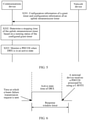
- FIG. 2 is a flowchart of the communication method according to Embodiment 1 of this application. As shown in FIG. 2 , the method provided in this embodiment includes the following steps.
- Step S101 The network device sends configuration information to the communications device, where the configuration information includes a sending resource of a beam failure recovery request (beam failure recovery request).
- the sending resource is a physical uplink control channel (Physical Uplink Control Channel, PUCCH) or a media access control (Media Access Control, MAC) control element (Control Element) CE.
- PUCCH Physical Uplink Control Channel
- MAC Media Access Control
- the network device may send the configuration information to the communications device by using RRC signaling.
- Step S102 When a beam failure (beam failure) occurs in a secondary cell of the communications device, the communications device sends the beam failure recovery request to the network device by using the PUCCH or the MAC CE.
- beam failure beam failure
- Bandwidth may be increased for user equipment by using a carrier aggregation (Carrier Aggregation, CA) technology, and the communications device may simultaneously aggregate a plurality of cells (cell) during CAto perform signaling scheduling and service transmission.
- the plurality of cells aggregated by the communications device include a primary serving cell (Primary cell, or referred to as a primary cell) and a secondary serving cell (Secondary cell, or referred to as a secondary cell).
- Primary cell Primary cell
- Secondary cell Secondary cell
- the communications device may send and receive data by using a beamforming (beamforming) technology.
- a beamforming beamforming
- service quality of a beam used to serve the communications device also changes.
- the beam failure occurs in the communications device when the service quality of the beam used to serve the communications device cannot meet a requirement.
- the communications device sends, based on the received configuration information, the beam failure recovery request to the network device by using the PUCCH or the MAC CE.
- the PUCCH is a PUCCH of the primary cell of the UE, or a PUCCH of another secondary cell of the UE.
- the beam failure recovery request is sent by using the PUCCH and the MAC CE, to avoid reserving excessive time-frequency resources used to send a random access preamble sequence, thereby effectively avoiding a resource waste.
- Step S103 The communications device determines an active state time of DRX based on a status of the beam failure recovery request.
- the status of the beam failure recovery request includes a sent state and a suspended state.
- the DRX includes two states: an active (active) state and an inactive (inactive) state.
- the communications device configured with the DRX monitors a physical downlink control channel (Physical Downlink Control Channel, PDCCH) within the active state time of the DRX, and the communications device does not monitor the PDCCH within an inactive state time of the DRX. Therefore, power consumption of the communications device can be reduced.
- PDCCH Physical Downlink Control Channel
- the network device After the communications device sends the beam failure recovery request by using the PUCCH, the network device returns a response message to the communications device.
- the response message includes information about the new beam, and the communications device may transmit data by using the information about the new beam. Therefore, the communications device needs to accurately receive the response message of the beam failure recovery request.
- the communications device needs to monitor the PDCCH after sending the beam failure recovery request. Therefore, after sending the beam failure recovery request, the communications device needs to ensure that the DRX is in the active state. Specifically, by using the following several manners, it may be ensured that the DRX is in the active state after the communications device sends the beam failure recovery request.
- the configuration information further includes a value of a response window timer.
- the communications device controls the response window timer (Response Window Timer) to start (start).
- response window timer works, the DRX is in the active state, to be specific, a working time of the response window timer is the active state time of the DRX. That the response window timer works means that the response window timer is started.
- the value of the response window timer is timing duration.
- the communications device controls the response window timer to stop (stop), where the first indication may be a PDCCH processed by using a cell-radio network temporary identifier (Cell-RadioNetworkTemporaryIdentifier, C-RNTI).
- C-RNTI Cell-RadioNetworkTemporaryIdentifier
- FIG. 3 is a schematic diagram of a status of DRX after the communications device sends the beam failure recovery request.
- the DRX when the response window timer is started, the DRX is turned on, in other words, the DRX is in an active state.
- the communications device receives the PDCCH processed by using the C-RNTI, the communications device controls the response window timer to stop, and the DRX is turned off when the response window timer is stopped. It can be learned from FIG. 3 that when the communications device receives the PDCCH processed by using the C-RNTI, the response window timer has not expired, to be specific, there is still a time period before the response window timer expires.
- the network device receives, based on the configured sending resource, the beam failure recovery request sent by the communications device, and determines the active state time of the DRX of the communications device based on a receiving time of the beam failure recovery request and the value of the response window timer.
- the network device determines that a time from the receiving time of the beam failure recovery request to a time at which the response window timer is stopped is the active state time of the DRX.
- the network device may send the response message of the beam failure recovery request to the communications device within the active state time of the DRX of the communications device.
- the communications device after sending the beam failure recovery request, the communications device immediately starts the response window timer, and when the response window timer works, the DRX is in the active state, so that it is ensured that the communications device can accurately receive the response message of the beam failure recovery request.
- the response window timer is immediately stopped, thereby reducing a quantity of monitoring times of the communications device.
- the configuration information further includes indication information of a first time, and the first time is a time for which the communications device delays, after sending the beam failure recovery request, starting a response window timer.
- the communications device controls, based on the configuration information after a delay of the first time, the response window timer to start, and a working time of the response window timer is the active state time of the DRX.
- a difference between the second manner and the first manner is that in the first manner, after sending the beam failure recovery request, the communications device immediately starts the response window timer, but in the second manner, after sending the beam failure recovery request, the communications device starts the response window timer after the delay of the first time.
- the first time is specified by a protocol, and the configuration information does not need to carry the indication information of the first time.
- the first time includes X symbols, and a value of X is greater than 0.
- the value of X is 2 or 3.
- the symbol is a time domain symbol, and for example, the symbol is an orthogonal frequency division multiplexing (Orthogonal Frequency Division Multiplexing, OFDM) symbol.
- the communications device controls the response window timer to stop, where the first indication may be a PDCCH processed by using a C-RNTI.
- FIG. 4 is a schematic diagram of a status of DRX after the communications device sends the beam failure recovery request.
- the communications device starts the response window timer after a delay of the X symbols.
- the response window timer is started, the DRX is turned on, in other words, the DRX is in the active state.
- the communications device receives the PDCCH processed by using the C-RNRI, the communications device controls the response window timer to stop, and the DRX is turned off when the response window timer is stopped. It can be learned from FIG. 4 that when the communications device receives the PDCCH processed by using the C-RNTI, the response window timer has not expired, to be specific, there is still a time period before the response window timer expires.
- the network device receives, based on the configured sending resource, the beam failure recovery request sent by the communications device, and determines the active state time of the DRX of the communications device based on a receiving time of the beam failure recovery request, the first time, and a value of the response window timer.
- the network device may send the response message of the beam failure recovery request to the communications device within the active state time of the DRX of the communications device. After the communications device sends the beam failure recovery request, the network device needs to process the beam failure recovery request, and the communications device cannot immediately receive the response message returned by the network device.
- the communications device after sending the beam failure recovery request, the communications device starts the response window timer after the delay of the X symbols, and when the response window timer works, the DRX is in the active state. In this manner, it can be ensured that the communications device can accurately receive the response message of the beam failure recovery request, and the power consumption of the communications device is further reduced.
- the communications device determines that a time in which the beam failure recovery request is in a suspended state is the active state time of the DRX.
- the communications device When the beam failure recovery request is suspended, the communications device needs to send, when there is an uplink resource that can be used to send the beam failure recovery request, the beam failure recovery request by using the uplink resource.
- the communications device sends the beam failure recovery request by using the PUCCH, if the beam failure recovery request is suspended, the DRX is supposed to be in the active state, and the communications device needs to monitor the PDCCH until the suspended state of the beam failure recovery request is canceled.
- the PUCCH is a PUCCH of the primary cell of the communications device, or a PUCCH of another secondary cell of the communications device.
- the suspended state of the beam failure recovery request may be canceled when the following condition is met:
- the communications device cancels the suspended state of the beam failure recovery request, where the first indication may be a PDCCH processed by using a C-RNTI; when there is an opportunity for sending the beam failure recovery request but a quantity of sending times of the beam failure recovery request reaches a maximum quantity, the suspended state of the beam failure recovery request is canceled; or when there is an opportunity for sending the beam failure recovery request but a radio link failure occurs, the suspended state of the beam failure recovery request is canceled.
- the suspended state of the beam failure recovery request may be canceled when the foregoing condition is met, or may be canceled when another condition is met. This is not limited in this application.
- the DRX is in the active state when the beam failure recovery request is suspended, so that the communications device can monitor the PDCCH when the beam failure recovery request is suspended, and it is ensured that the communications device can accurately receive the response message of the beam failure recovery request, and cancel the suspended state of the beam failure recovery request in time after receiving the PDCCH processed by using the C-RNTI. Therefore, a quantity of monitoring times of the communications device is reduced, and the power consumption of the communications device is reduced.
- the communications device when the beam failure occurs in the secondary cell of the communications device, the communications device sends the beam failure recovery request to the network device by using the PUCCH or the MAC CE, and determines the active state time of the DRX based on the status of the beam failure recovery request, and the communications device monitors the PDCCH within the active state time of the DRX. Therefore, it can be ensured that when the power consumption of the communications device is reduced, the communications device accurately receives the response message of the beam failure recovery request.
- FIG. 5 is a flowchart of a communication method according to Embodiment 2 of this application.
- the method provided in this embodiment includes the following steps.
- Step S201 A network device sends configuration information of a configured grant timer (configured grant Timer) and configuration information of an uplink retransmission timer (drx-RetransmissionTimer UL) to the communications device.
- a configured grant timer Configured grant Timer
- configuration information of an uplink retransmission timer drx-RetransmissionTimer UL
- the configured grant timer may alternatively have another name, for example, a first timer.
- a name of the configured grant timer is not limited in this application.
- the following uses the configured grant timer as an example for description.
- the communications device cannot use a semi-persistent scheduling (Semi-Persistent Scheduling, SPS) resource or a resource of a type 1 (type1) to perform new transmission for an HARQ process corresponding to the configured grant timer.
- a parameter of the configured grant timer may be configured by using radio resource control (Radio Resource Control, RRC) signaling.
- the configuration information of the configured grant timer includes a value of the configured grant timer
- the configuration information of the uplink retransmission timer includes a value of the uplink retransmission timer.
- Step S202 The communications device determines a stopping time of the uplink retransmission timer based on a running status of the configured grant timer, where DRX of the communications device is in an active state when the uplink retransmission timer works.
- Step S203 The communications device monitors a PDCCH when the DRX of the communications device is in the active state.
- the configured grant timer may stop when the communications device receives dynamic grant associated with the HARQ process corresponding to the configured grant timer.
- the communications device determines a stopping time of the uplink retransmission timer based on a running status of the configured grant timer is specifically: When the configured grant timer expires, if the uplink retransmission timer is working, the communications device controls the uplink retransmission timer to stop.
- the configured grant timer is started by the communications device after the first sending of first data.
- the network device first allocates one or more grant-free transmission areas (or referred to as grant-free transmission resources) to the communications device, and the communications device directly sends uplink data (for example, uplink grant-free data) in the grant-free transmission areas without going through a process from service requesting to uplink grant by the network device.
- the grant-free transmission is contention-based transmission, and a plurality of communications devices may simultaneously preempt one transmission resource. Therefore, the communications device uses a K repeated transmission technology, to be specific, the communications device transmits a same transmission block (Transmission Block, TB) in K consecutive transmission cycles, to improve a transmission success rate. In other words, the communications device repeatedly sends same data for K times, where K is an integer greater than 0.
- the communications device starts the configured grant timer after the first sending of the first data.
- the first sending of the first data indicates that the first data is sent for the first time.
- the communications device starts an uplink round trip time timer (drx-HARQ Round Trip Time Timer Uplink, drx-HARQ-RTT-TimerUL) after the first sending of the first data, starts the uplink retransmission timer after the uplink round trip time timer expires, and stops the uplink retransmission timer after the configured grant timer expires.
- the configured grant timer, the uplink round trip time timer, and the uplink retransmission timer are all associated with a same HARQ process, and the HARQ process is an HARQ process for processing the first data.
- one "drx-HARQ-RTT-TimerUL (uplink round trip time timer)" is defined for each HARQ process.
- the communications device After the first sending of uplink data of an uplink HARQ process, it may be assumed that the communications device receives, at least after symbols whose quantity is equal to a value of the drx-HARQ-RTT-TimerUL, downlink control information (Downlink Control Information, DCI) that is sent by the network device and that indicates the transmission.
- DCI Downlink Control Information
- the drx-HARQ-RTT-TimerUL is configured by the network device for the communications device. Therefore, the communications device does not need to monitor the PDCCH when the drx-HARQ-RTT-TimerUL is running.
- the communications device starts a drx-RetransmissionTimerUL (uplink retransmission timer) for the HARQ process when the drx-HARQ-RTT-TimerUL expires.
- the communications device monitors a PDCCH used for HARQ retransmission.
- a length of time specified by the drx-RetransmissionTimerUL is related to a flexibility requirement of a network device scheduler.
- the network device needs to immediately send the DCI that indicates the transmission.
- the network device needs to reserve a radio resource for this.
- the time specified by the drx-RetransmissionTimer UL may be configured relatively short.
- the drx-RetransmissionTimerUL specifies a maximum quantity of slots for continuously monitoring the PDCCH after the communications device is expected to receive the DCI (sent after the drx-HARQ-RTT-TimerUL expires) that indicates the transmission.
- the uplink round trip time timer and the uplink retransmission timer that are used in this embodiment may use a configuration the same as that during grant-based transmission, or may be additionally configured by the network device.
- FIG. 6 is a schematic diagram of a status of DRX during the uplink grant-free transmission.
- the communications device starts the configured grant timer and the uplink round trip time timer of the HARQ process after the first sending of the first data, starts the uplink retransmission timer after the uplink round trip time timer expires, and stops the uplink retransmission timer after the configured grant timer expires.
- the DRX is in the active state when the uplink retransmission timer works.
- the configured grant timer is started by the communications device after the uplink round trip time timer expires.
- the communications device controls, after the first sending of first data, the uplink round trip time timer to start, and after the uplink round trip time timer expires, controls the uplink retransmission timer and the configured grant timer to start.
- the DRX is in the active state when the uplink retransmission timer works.
- FIG. 7 is a schematic diagram of another status of DRX during the uplink grant-free transmission.
- the communications device starts the uplink round trip time timer of the HARQ process after the first sending of the first data, and starts the uplink retransmission timer and the configured grant timer of the HARQ process after the uplink round trip time timer expires.
- the DRX is in the active state when the uplink retransmission timer works.
- the uplink retransmission timer is stopped after the configured grant timer expires.
- the configured grant timer is started by the communications device when the first data is sent.
- a sending time of the first data is a time from a time at which the first sending of the first data is started to a time at which K th sending of the first data is finished. Therefore, the communications device may start the configured grant timer at any time between a starting moment of the first sending of the first data and a finishing moment of the K th sending of the first data. For example, the communications device starts the configured grant timer at the starting moment of the first sending of the first data, immediately starts the configured grant timer after the first sending of the first data, starts the configured grant timer at a starting moment of the second sending of the first data, or immediately starts the configured grant timer after the second sending of the first data.
- the network device determines, based on the configuration information of the grant timer and the configuration information of the uplink retransmission timer, that the DRX of the communications device is in the active state.
- the network device may send the retransmission indication during the uplink grant-free transmission to the communications device when the DRX of the communications device is in the active state.
- the uplink round trip time timer, the uplink retransmission timer, and the configured grant timer all correspond to or are all associated with a same HARQ process.
- the communications device receives the configuration information of the configured grant timer and the configuration information of the uplink retransmission timer that are sent by the network device, and the communications device determines the stopping time of the uplink retransmission timer based on the running status of the configured grant timer.
- the DRX of the communications device is in the active state when the uplink retransmission timer works, and the communications device monitors the PDCCH when the DRX is in the active state.
- the uplink retransmission timer is controlled to stop, so that accurate reception of the retransmission indication during the uplink grant-free transmission can be ensured, and additional monitoring by the communications device can be reduced. Therefore, power consumption of the communications device can be reduced.
- FIG. 8 is a flowchart of a communication method according to Embodiment 3 of this application.
- the method provided in this embodiment includes the following steps.
- Step S301 A network device sends configuration information of a configured grant timer to the communications device.
- Step S302 When sending data, the communications device determines an active state time of DRX based on a running status of the configured grant timer.
- the data may be first data for the first sending.
- Step S303 The communications device monitors a PDCCH when the DRX is in an active state.
- the network device determines the active state time of the DRX of the communications device based on the data sent by the communications device and the configuration information of the configured grant timer.
- the network device sends the retransmission indication during uplink grant-free transmission to the communications device when the DRX of the communications device is in the active state.
- the communications device controls, after the first sending of the first data, the configured grant timer to start, and the DRX is in the active state when the configured grant timer works.
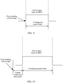
- FIG. 9 is a schematic diagram of still another status of DRX during the uplink grant-free transmission.
- the communications device immediately starts the configured grant timer after the first sending of the first data.
- the DRX is turned on, in other words, the DRX is in the active state.
- the communications device monitors the PDCCH when the DRX is in the active state.
- the DRX is turned on after the first sending of the first data, and the communications device monitors the PDCCH within the active time of the DRX, so that it is ensured that the communications device can receive the retransmission indication during the uplink grant-free transmission.
- the communications device receives indication information that is of a first time and that is sent by the network device, where the first time is a time for which the communications device delays, after the first sending of the first data, starting the configured grant timer, and the communications device controls, after the first sending of the first data, the configured grant timer to start after a delay of the first time, where the DRX is in the active state when the configured grant timer works.
- the first time may be preset by the communications device.
- the communications device controls, after the first sending of the first data, an uplink round trip time timer of an HARQ process for processing the first data to start, and after the uplink round trip time timer expires, controls the configured grant timer to start.
- the first time is implemented by using a timer, and the first time is a timing time of the uplink round trip time timer.
- FIG. 10 is a schematic diagram of yet another status of DRX during the uplink grant-free transmission.
- the communications device immediately starts the uplink round trip time timer of the HARQ process after the first sending of the first data, and starts the configured grant timer after the uplink round trip time timer expires.
- the DRX is turned on, in other words, the DRX is in the active state, and the communications device monitors the PDCCH when the DRX is in the active state.
- the DRX is turned on after the delay of the first time, and the communications device monitors the PDCCH within the active time of the DRX, so that it is ensured that the communications device can receive the retransmission indication during the uplink grant-free transmission.
- the communications device monitors the PDCCH within the active time of the DRX, so that it is ensured that the communications device can receive the retransmission indication during the uplink grant-free transmission.
- power consumption of the communications device can be further reduced.
- the communications device controls, after the first sending of the first data, an uplink round trip time timer and the configured grant timer of an HARQ process for processing the first data to start, and after the uplink round trip time timer expires and when the configured grant timer works, the DRX is in the active state.
- FIG. 11 is a schematic diagram of still yet another status of DRX during the uplink grant-free transmission.
- the communications device starts the uplink round trip time timer and the configured grant timer of the HARQ process after the first sending of the first data.
- the DRX is turned on, and the communications device monitors the PDCCH when the DRX is in the active state.
- the DRX is turned on after a delay of a time (a timing time of the uplink round trip time timer), and the communications device monitors the PDCCH within the active time of the DRX, so that it is ensured that the communications device can receive the retransmission indication during the uplink grant-free transmission.
- a delay of a time a timing time of the uplink round trip time timer
- the communications device controls, when the first data is sent, the configured grant timer to start, and the DRX is in the active state when the configured grant timer works.
- an uplink round trip time timer, the uplink retransmission timer, and the configured grant timer all correspond to or are associated with a same HARQ process.
- the uplink round trip time timer and the uplink retransmission timer that are used in this embodiment may use a configuration the same as that during grant-based transmission, or may be additionally configured by the network device.
- the communications device receives the configuration information that is of the configured grant timer and that is sent by the network device. After the first sending of the first data, the communications device determines the active state time of the DRX based on the running status of the configured grant timer. The communications device monitors the PDCCH when the DRX is in the active state. By controlling the active state of the DRX based on the running status of the configured grant timer, accurate reception of the retransmission indication during the uplink grant-free transmission can be ensured, and additional monitoring by the communications device can be reduced. Therefore, the power consumption of the communications device is reduced.
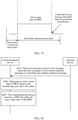
- FIG. 12 is a flowchart of a communication method according to Embodiment 4 of this application.
- the method provided in this embodiment includes the following steps.
- Step S401 A network device sends indication information to the communications device, where the indication information is used to indicate a retransmission manner used for downlink transmission, and the retransmission manner is a grant-based (grant-based) transmission or grant-free transmission manner.
- the network device may send the indication information by using RRC signaling or DCI.
- the indication information may be carried by using one bit (bite). For example, if a value of the bit is 1, it indicates that the retransmission manner is the grant-based transmission manner, and if the value of the bit is 0, it indicates that the retransmission manner is the grant-free transmission manner.
- the network device sends retransmitted data to the communications device in the retransmission manner used for the downlink transmission.
- Step S402 The communications device controls running statuses of a downlink round trip time timer and a downlink retransmission timer based on the indication information.
- the downlink round trip time timer and the downlink retransmission timer are timers of an HARQ process associated with the downlink retransmitted data.
- FIG. 13 is a schematic diagram of a status of DRX when the retransmission manner is the grant-based transmission manner.
- the communications device controls, after PUCCH transmission, the downlink round trip time timer to start, after the downlink round trip time timer expires, controls the downlink retransmission timer to start.
- the DRX is in an active state when the downlink retransmission timer works, and the communications device monitors a PDCCH when the DRX is in the active state.
- the communications device When the downlink retransmission timer runs, if the communications device receives grant-based retransmission scheduling, the communications device controls the downlink retransmission timer to stop, and the grant-based retransmission scheduling is sent by the network device. The communications device stops the downlink retransmission timer when receiving the grant-based retransmission scheduling, to avoid unnecessary monitoring, and further reduce power consumption of the communications device.
- the communications device controls, after the PUCCH transmission, the downlink round trip time timer and the downlink retransmission timer not to start.
- the communications device does not need to receive scheduling from the network device, and the communications device performs retransmission by using a pre-configured grant-free transmission resource. Therefore, the communications device does not need to monitor the PDCCH.
- the retransmission manner used for the downlink transmission is the grant-free transmission manner, if the communications device starts the downlink round trip time timer and the downlink retransmission timer, a waste of the power consumption of the communications device is caused.
- both of the downlink round trip time timer and the downlink retransmission timer correspond to or are associated with a same HARQ process.
- the communications device does not know whether the grant-free transmission or grant-based transmission is used for the downlink transmission, and the communications device controls, after the PUCCH transmission, the downlink round trip time timer and the downlink retransmission timer to start.
- the retransmission manner used for the downlink transmission is the grant-free transmission manner
- the waste of the power consumption of the communications device is caused.
- the network device indicates the retransmission manner used for the downlink transmission, so that the communications device is prevented from starting the downlink round trip time timer and the downlink retransmission timer when the grant-free transmission is used for the downlink transmission. Therefore, the power consumption of the communications device is reduced and a resource waste is avoided.
- the uplink round trip time timer and the uplink retransmission timer that are used in this embodiment may use a configuration the same as that during the grant-based transmission, or may be additionally configured by the network device.
- FIG. 14 is a flowchart of a communication method according to Embodiment 5 of this application.
- the method provided in this embodiment includes the following steps.
- Step S501 A network device sends configuration information of a downlink round trip time timer and configuration information of a downlink retransmission timer to the communications device.
- the configuration information of the downlink round trip time timer includes a value of the downlink round trip time timer, and the configuration information of the downlink retransmission timer includes a value of the downlink retransmission timer.
- Step S502 The communications device controls, after PUCCH transmission, the downlink round trip time timer to start.
- Step S503 After the downlink round trip time timer expires, the communications device controls the downlink retransmission timer to start.
- the DRX is in an active state when the downlink retransmission timer works, and the communications device monitors a PDCCH when the DRX is in the active state.
- the network device sends downlink data for grant-free transmission to the communications device based on the configuration information of the downlink round trip time timer and the configuration information of the downlink retransmission timer.
- Step S504 When the downlink retransmission timer runs, if the communications device receives the downlink data for the grant-free transmission, the communications device controls the downlink retransmission timer to stop.
- the downlink data for the grant-free transmission received by the communications device is associated with an HARQ process corresponding to the downlink retransmission timer.
- the network device uses a K times repeated transmission technology. Therefore, the downlink data during the grant-free transmission may be downlink data for X th sending, where a value of X ranges from 1 to K, and K is an integer greater than 0.
- FIG. 15 is a schematic diagram of a status of DRX during grant-based downlink transmission.
- the communications device controls, after the PUCCH transmission, the downlink round trip time timer to start, and after the downlink round trip time timer expires, controls the downlink retransmission timer to start.
- the DRX is in the active state when the downlink retransmission timer works, and the communications device monitors the PDCCH when the DRX is in the active state, to receive downlink retransmitted data.
- the communications device When the downlink retransmission timer runs, if the communications device receives the downlink data for the grant-free transmission, the communications device controls the downlink retransmission timer to stop, to avoid unnecessary monitoring, and further reduce power consumption of the communications device.
- the downlink round trip time timer and the downlink retransmission timer that are used in this embodiment may use a configuration the same as that of grant-based transmission, or may be additionally configured by the network device.
- both of the downlink round trip time timer and the downlink retransmission timer correspond to or are associated with a same HARQ process.
- the communications device controls, after the PUCCH transmission, the downlink round trip time timer to start, and after the downlink round trip time timer expires, controls the downlink retransmission timer to start.
- the DRX is in an active state when the downlink retransmission timer works, and the communications device monitors the PDCCH when the DRX is in the active state, so that the communications device can accurately receive retransmitted data when receiving data in a downlink grant-free transmission manner.
- the communications device controls the downlink retransmission timer to stop, to further reduce the power consumption of the communications device.
- FIG. 16 is a flowchart of a communication method according to Embodiment 6 of this application. As shown in FIG. 16 , the method provided in this embodiment includes the following steps.
- Step S601 A network device sends a monitoring cycle of a first message to a communications device, where the first message is a slot format indicator (Slot Format Indicator, SFI) message or a downlink pre-emption indicator (Pre-emption indicator) message.
- SFI Slot Format Indicator
- Pre-emption indicator Pre-emption indicator
- the monitoring cycle may be configured by using RRC signaling, or the monitoring cycle may alternatively be preset, and the monitoring cycle is in a slot unit. Both of the SFI and the downlink pre-emption indicator are sent cyclically.
- the SFI is used to indicate that a slot is an uplink slot, a downlink slot, or a flexible (flexible or unknown) slot.
- the SFI is further used to indicate that a symbol included in the slot is an uplink symbol, a downlink symbol, or a flexible symbol.
- the uplink slot is used for uplink transmission, and the downlink slot is used for downlink transmission.
- the uplink symbol is used for the uplink transmission, the downlink symbol is used for the downlink transmission.
- the flexible slot is a special slot, to be specific, the flexible slot may be used for the uplink transmission or the downlink transmission. Similarly, the flexible symbol may also be used for the downlink transmission or the uplink transmission.
- a 5G system supports an enhanced mobile broadband (enhanced mobile broadband, eMBB) service, an ultra reliable and low latency communications (ultra reliable and low latency communications, URLLC) service, and a massive machine type communications (massive machine type communications, mMTC) service.
- eMBB enhanced mobile broadband
- URLLC ultra reliable and low latency communications
- mMTC massive machine type communications
- the network device may allocate a resource to the URLLC service data in a preemption (preemption) manner.
- Preemption indicates that the network device selects some or all of time-frequency resources that have been allocated and that are used to transmit the eMBB service data, to transmit the URLLC service data, and the network device does not send the eMBB service data on the time-frequency resources that are used to transmit the URLLC service data.
- the communications device does not know that the URLLC service of the network device preempts the time-frequency resources used to transmit the eMBB service data. If the communications device does not know that the resources are preempted, the communications device receives the downlink data on the preempted resources, and consequently a resource waste is caused. Therefore, the network device needs to notify the communications device by using the downlink pre-emption indicator. To avoid the resource waste, it needs to be ensured that the communications device can accurately receive the downlink pre-emption indicator.
- Step S602 The communications device determines an active state time of DRX based on the monitoring cycle and a slot index.
- the communications device receives the monitoring cycle of the first message sent by the network device, and determines the active state time of the DRX based on the monitoring cycle and the slot index.
- the communications device determines that a slot corresponding to the slot index is the active state time of the DRX
- the communications device determines that a slot corresponding to the slot index is the active state time of the DRX
- a MAC entity of the communications device has at least one hybrid automatic repeat request HARQ process used for the downlink transmission, the communications device determines that the slot corresponding to the slot index is the active state time of the DRX
- Step S603 The communications device monitors the PDCCH within the active state time of the DRX
- the network device also determines the active state time of the DRX of the communications device based on the monitoring cycle and the slot index.
- a manner in which the network device determines the active state time of the DRX of the communications device is the same as a manner in which the communications device determines the active state time of the DRX. Details are not described herein again.
- the network device sends the first message to the communications device when the DRX of the communications device is in the active state.
- the communications device monitors the PDCCH within the active state time of the DRX.
- FIG. 17 is a schematic structural diagram of a communications device according to Embodiment 7 of this application. As shown in FIG. 17 , the communications device provided in this embodiment includes:
- the receiving module 11 is further configured to monitor a physical downlink control channel PDCCH within the active state time of the DRX.
- the configuration information further includes a value of a response window timer
- the processing module 13 is specifically configured to: after the beam failure recovery request is sent, control the response window timer to start, where a working time of the response window timer is the active state time of the DRX.
- the configuration information further includes indication information of a first time, the first time is a time for which the communications device delays, after sending the beam failure recovery request, starting the response window timer, and the processing module 13 is specifically configured to: after the beam failure recovery request is sent, control the response window timer to start after a delay of the first time, where the working time of the response window timer is the active state time of the DRX.
- the receiving module 11 is further configured to receive a first indication; and the processing module 13 is further configured to: when the receiving module 11 receives the first indication, control the response window timer to stop.
- the first time includes X symbols, and a value of X is greater than 0.
- the determining module 12 is specifically configured to: when the beam failure recovery request is suspended, determine that a time in which the beam failure recovery request is in a suspended state is the active state time of the DRX.
- the communications device provided in this embodiment may be configured to perform the method performed by the communications device in Embodiment 1. Their specific implementations and technical effects are similar. Details are described herein again.
- Embodiment 7 may be combined into a transceiver module, which implements similar functions. This is not described herein again.
- the communications device in this embodiment is a terminal, refer to a device shown in FIG. 18 .
- the device includes a processor 801, an application processor, a memory, a user interface, and some other elements (including a device not shown in the figure, for example, a power supply).
- the foregoing processing unit may be the processor 801, and implements a corresponding function.
- the sending unit and/or the receiving unit may be a wireless transceiver 803 shown in the figure, and the wireless transceiver 803 implements a corresponding function by using an antenna. It may be understood that the elements shown in the figure are merely examples, and are not necessary elements for implementing this embodiment.
- the communications device in this embodiment is the terminal, refer to a device shown in FIG. 19 .
- the device may implement a function similar to that of the processor shown in FIG. 18 .
- the device includes a processor, a data sending processor, and a processor.
- the foregoing processing unit may be the processor 901, and implements a corresponding function.
- the sending unit may be a data sending processor 903 in FIG. 19
- the receiving unit may be a data receiving processor 905 in FIG. 19 .
- the figure shows a channel encoder and a channel decoder, it may be understood that the modules are merely examples, and do not constitute a limitation on this embodiment.
- FIG. 20 shows another form of this embodiment.
- a processing apparatus 1000 includes modules such as a modulation subsystem, a central processing subsystem, and a peripheral subsystem.
- the communications device in this embodiment may be used as the modulation subsystem in the processing apparatus 1000.
- the modulation subsystem may include a processor 1003 and an interface 1004.
- the processor 1003 implements a function of the foregoing processing unit
- the interface 1004 implements a function of the foregoing sending unit and/or receiving unit.
- the modulation subsystem includes a memory 1006, the processor 1003, and a program that is stored in the memory and that may run on the processor, and the processor implements the method in one of Embodiment 1 to Embodiment 5 when executing the program.
- the memory 1006 may be nonvolatile or volatile, and may be located in the modulation subsystem or the processing apparatus 1000, provided that the memory 1006 may be connected to the processor 1003.
- FIG. 21 is a schematic structural diagram of a network device according to Embodiment 8 of this application. As shown in FIG. 21 , the network device provided in this embodiment includes:
- the configuration information further includes indication information of a first time, and the first time is a time for which the communications device delays, after sending the beam failure recovery request, starting the response window timer.
- the first time includes X symbols, and a value of X is greater than 0.
- Embodiment 8 may be combined into a transceiver module, and implement similar functions. This is not described herein again.
- the network device provided in this embodiment may be configured to perform the method performed by the network device in Embodiment 1. Their specific implementations and technical effects are similar. Details are described herein again.
- the device includes a processor 1201, an application processor, a memory, a user interface, and some other elements (including devices not shown in the figure, for example, a power supply).
- the foregoing processing unit may be the processor 1201, and implements a corresponding function.
- the sending unit and/or the receiving unit may be a wireless transceiver 1203 shown in the figure, and implement and/or implements a corresponding function by using an antenna. It may be understood that the elements shown in the figure are merely examples, and are not necessary elements for implementing this embodiment.
- the device includes a processor, a data sending processor, and a processor.
- the foregoing processing unit may be the processor 1301, and implements a corresponding function.
- the sending unit may be a data sending processor 1303 in FIG. 23
- the receiving unit may be a data receiving processor 1305 in FIG. 23 .
- the figure shows a channel encoder and a channel decoder, it may be understood that the modules are merely examples, and do not constitute a limitation on this embodiment.
- FIG. 24 shows another form of this embodiment.
- a processing apparatus 1400 includes modules such as a modulation subsystem, a central processing subsystem, and a peripheral subsystem.
- the communications device in this embodiment may be used as the modulation subsystem in the processing apparatus 1400.
- the modulation subsystem may include a processor 1403 and an interface 1404.
- the processor 1403 implements a function of the foregoing processing unit
- the interface 1404 implements a function of the foregoing sending unit and/or receiving unit.
- the modulation subsystem includes a memory 1406, the processor 1403, and a program that is stored in the memory and that may run on the processor, and the processor implements the method in one of Embodiment 1 to 4 and Embodiment 6 when executing the program.
- the memory 1406 may be nonvolatile or volatile, and may be located in the modulation subsystem or the processing apparatus 1400, provided that the memory 1406 may be connected to the processor 1403.
- a computer-readable storage medium is provided, and an instruction is stored in the computer-readable storage medium.
- the instruction is executed, the method steps performed by the network device in Embodiment 1 are performed.
- Embodiment 9 of this application provides a communications device.
- the communications device may perform the method steps performed by the communications device in Embodiment 2 to Embodiment 6.
- the communications device may be a terminal, or may be hardware implementing a similar function.
- the communications device includes at least one processor.
- the processor is coupled to a memory.
- the processor is configured to read an instruction in the memory, and perform, based on the instruction, the method steps performed by the communications device in Embodiment 2 to Embodiment 6.
- Embodiment 10 of this application provides a network device.
- the network device may perform the method steps performed by the network device in Embodiment 2 to Embodiment 6.
- the network device includes at least one processor.
- the processor is coupled to a memory.
- the processor is configured to read an instruction in the memory, and perform, based on the instruction, the method steps performed by the network device in Embodiment 2 to Embodiment 6.
- Embodiment 11 of this application provides a computer-readable storage medium.
- the computer-readable storage medium stores an instruction, and when the instruction is executed, the method steps performed by the communications device in Embodiment 2 to Embodiment 6 are performed.
- Embodiment 12 of this application provides a computer-readable storage medium.
- the computer-readable storage medium stores an instruction, and when the instruction is executed, the method steps performed by the network device in Embodiment 2 to Embodiment 6 are performed.
- the memory may be integrated into the processor, or may be independent of the processor. This is not limited in this embodiment.
- the processor in the embodiments may be a general purpose processor, a digital signal processor (Digital Signal Processor, DSP), an application specific integrated circuit (Application Specific Integrated Circuit, ASIC), a field programmable gate array (Field Programmable Gate Array, FPGA) or another programmable logical device, a discrete gate or transistor logic device, or a discrete hardware component. It may implement or perform the methods, the steps, and logical block diagrams that are disclosed in the embodiments of this application.
- the general purpose processor may be a microprocessor, or the processor may be any conventional processor or the like.
- Steps of the methods disclosed with reference to the embodiments of this application may be directly executed and accomplished by using a hardware decoding processor, or may be executed and accomplished by using a combination of hardware and software modules in the decoding processor.
- a software module may be located in a mature storage medium in the art, such as a random access memory (Random Access Memory, RAM), a flash memory, a read-only memory (Read-Only Memory, ROM), a programmable read-only memory, an electrically erasable programmable memory, a register, or the like.
- the storage medium is located in the memory 1002, and a processor 1001 reads instructions in the memory 1002 and completes the steps in the foregoing methods in combination with hardware of the processor.
- the disclosed system, apparatus, and method may be implemented in other manners.
- the described apparatus embodiment is merely an example.
- the unit division is merely logical function division and may be other division in actual implementation.
- a plurality of units or components may be combined or integrated into another system, or some features may be ignored or not performed.
- the displayed or discussed mutual couplings or direct couplings or communication connections may be implemented by using some interfaces.
- the indirect couplings or communication connections between the apparatuses or units may be implemented in electronic, mechanical, or other forms.
- the units described as separate parts may or may not be physically separate, and parts displayed as units may or may not be physical units, may be located in one position, or may be distributed on a plurality of network units. Some or all of the units may be selected based on actual requirements to achieve the objectives of the solutions of the embodiments.
- the functions When the functions are implemented in the form of a software functional unit and sold or used as an independent product, the functions may be stored in a computer-readable storage medium. Based on such an understanding, the technical solutions of this application essentially, or the part contributing to the prior art, or a part of the technical solutions may be implemented in the form of a software product.
- the computer software product is stored in a storage medium and includes several instructions for instructing a computer device (which may be a personal computer, a server, or a network device) or a processor (processor) to perform all or a part of the steps of the methods described in the embodiments of this application.
- the foregoing storage medium includes: any medium that can store program code, such as a USB flash drive, a removable hard disk, a read-only memory (Read-Only Memory, ROM), a random access memory (Random Access Memory, RAM), a magnetic disk, or an optical disc.
- program code such as a USB flash drive, a removable hard disk, a read-only memory (Read-Only Memory, ROM), a random access memory (Random Access Memory, RAM), a magnetic disk, or an optical disc.
Landscapes
- Engineering & Computer Science (AREA)
- Computer Networks & Wireless Communication (AREA)
- Signal Processing (AREA)
- Mobile Radio Communication Systems (AREA)
Claims (8)
- Kommunikationsverfahren, umfassend:Empfangen (S101) von Konfigurationsinformationen, die durch eine Netzwerkvorrichtung gesendet werden, durch eine Kommunikationsvorrichtung,wobei die Konfigurationsinformationen eine Senderessource der Strahlausfallwiederherstellungsanforderung umfassen und es sich bei der Senderessource um einen physischen Uplink-Steuerkanal (physical uplink control channel - PUCCH) oder ein Steuerelement zur Medienzugriffssteuerung (media access control control element - MAC CE) handelt;wenn ein Strahlausfall in einer Sekundärzelle der Kommunikationsvorrichtung auftritt, Senden (S102) der Strahlausfallwiederherstellungsanforderung an die Netzwerkvorrichtung durch die Kommunikationsvorrichtung unter Verwendung des PUCCH oder des MAC CE; undBestimmen (S103) einer Zeit im aktiven Zustand eines diskontinuierlichen Empfangs (dicontinuous reception - DRX) durch die Kommunikationsvorrichtung auf Grundlage eines Status der Strahlausfallwiederherstellungsanforderung, dadurch gekennzeichnet, dassdie Konfigurationsinformationen ferner Angabeinformationen zu einer ersten Zeit umfassen, wobei es sich bei der ersten Zeit um eine Verzögerungszeit der Kommunikationsvorrichtung nach dem Senden der Strahlausfallwiederherstellungsanforderung bis zum Starten eines Antwortfensterzeitgebers handelt, und das Bestimmen einer Zeit im aktiven Zustand des DRX durch die Kommunikationsvorrichtung auf Grundlage eines Status der Strahlausfallwiederherstellungsanforderung Folgendes umfasst:nachdem die Strahlausfallwiederherstellungsanforderung gesendet wurde, Steuern des Antwortfensterzeitgebers durch die Kommunikationsvorrichtung derart, dass er nach einer Verzögerung der ersten Zeit startet, wobei es sich bei einer Arbeitszeit des Antwortfensterzeitgebers um die Zeit im aktiven Zustand des DRX handelt.
- Verfahren nach Anspruch 1, ferner umfassend:Überwachen eines physischen Downlink-Steuerkanals (physical downlink control channel - PDCCH) durch die Kommunikationsvorrichtung innerhalb der Zeit im aktiven Zustand des DRX.
- Verfahren nach Anspruch 1, ferner umfassend:bei Empfang einer ersten Angabe, Steuern des Antwortfensterzeitgebers durch die Kommunikationsvorrichtung derart, dass er anhält.
- Verfahren nach Anspruch 1, wobei die erste Zeit X Symbole umfasst und ein Wert von X größer als 0 ist.
- Verfahren nach Anspruch 1 oder 2, wobei, wenn die Kommunikationsvorrichtung die Strahlausfallwiederherstellungsanforderung unter Verwendung des PUCCH sendet, das Bestimmen einer Zeit im aktiven Zustand des DRX durch die Kommunikationsvorrichtung auf Grundlage eines Status der Strahlausfallwiederherstellunganforderung Folgendes umfasst:wenn die Strahlausfallwiederherstellungsanforderung ausgesetzt ist, Bestimmen durch die Kommunikationsvorrichtung, dass es sich bei einer Zeit, in der sich die Strahlausfallwiederherstellungsanforderung in einem ausgesetzten Zustand befindet, um die Zeit im aktiven Zustand des DRX handelt.
- Kommunikationsverfahren, umfassend:Senden (S101) von Konfigurationsinformationen an eine Kommunikationsvorrichtung durch eine Netzwerkvorrichtung, dadurch gekennzeichnet, dassdie Konfigurationsinformationen eine Senderessource einer Strahlausfallwiederherstellungsanforderung und einen Wert eines Antwortfensterzeitgebers umfassen und es sich bei der Senderessource um einen physischen Uplink-Steuerkanal (PUCCH) oder ein Steuerelement zur Medienzugriffssteuerung (MAC CE) handelt;Empfangen (S102) der Strahlausfallwiederherstellungsanforderung durch die Netzwerkvorrichtung auf Grundlage der Senderessource; undBestimmen (S103) einer Zeit im aktiven Zustand des diskontinuierlichen Empfangs (DRX) der Kommunikationsvorrichtung durch die Netzwerkvorrichtung auf Grundlage einer Empfangszeit der Strahlausfallwiederherstellungsanforderung und des Werts des Antwortfensterzeitgebers,wobei die Konfigurationsinformationen ferner Angabeinformationen zu einer ersten Zeit umfassen und es sich bei der ersten Zeit um eine Verzögerungszeit nach dem Senden der Strahlausfallwiederherstellungsanforderung bis zum Starten eines Antwortfensterzeitgebers handelt.
- Kommunikationsvorrichtung, umfassend:ein Empfangsmodul (11), das dazu konfiguriert ist, Konfigurationsinformationen zu empfangen, die durch eineNetzwerkvorrichtung gesendet werden, dadurch gekennzeichnet, dassdie Konfigurationsinformationen eine Senderessource der Strahlausfallwiederherstellungsanforderung umfassen und es sich bei der Senderessource um einen physischen Uplink-Steuerkanal (PUCCH) oder ein Steuerelement zur Medienzugriffssteuerung (MAC CE) handelt;ein Sendemodul (12), das für Folgendes konfiguriert ist: wenn ein Strahlausfall in einer Sekundärzelle der Kommunikationsvorrichtung auftritt, Senden der Strahlausfallwiederherstellungsanforderung an die Netzwerkvorrichtung unter Verwendung des PUCCH oder des MAC CE; undein Verarbeitungsmodul (13), das dazu konfiguriert ist, eine Zeit im aktiven Zustand des DRX auf Grundlage eines Status der Strahlausfallwiederherstellungsanforderung zu bestimmen, wobei die Konfigurationsinformationen ferner Angabeinformationen zu einer ersten Zeit beinhalten, wobei es sich bei der ersten Zeit um eine Verzögerungszeit nach dem Senden der Strahlausfallwiederherstellungsanforderung bis zum Starten des Antwortfensterzeitgebers handelt, und das Verarbeitungsmodul insbesondere für Folgendes konfiguriert ist:nachdem die Strahlausfallwiederherstellungsanforderung gesendet wurde, Steuern des Antwortfensterzeitgebers derart, dass er nach einer Verzögerung der ersten Zeit startet, wobei es sich bei einer Arbeitszeit des Antwortfensterzeitgebers um die Zeit im aktiven Zustand des DRX handelt.
- Netzwerkvorrichtung, umfassend:ein Sendemodul (21), das dazu konfiguriert ist, Konfigurationsinformationen an eine Kommunikationsvorrichtung zu senden, dadurch gekennzeichnet, dassdie Konfigurationsinformationen eine Senderessource einer Strahlausfallwiederherstellungsanforderung und einen Wert eines Antwortfensterzeitgebers umfassen und es sich bei der Senderessource um einen physischen Uplink-Steuerkanal (PUCCH) oder ein Steuerelement zur Medienzugriffssteuerung (MAC CE) handelt;ein Empfangsmodul (22), das dazu konfiguriert ist, die Strahlausfallwiederherstellungsanforderung auf Grundlage derSenderessource zu empfangen; undein Verarbeitungsmodul (23), das dazu konfiguriert ist, eine Zeit im aktiven Zustand eines diskontinuierlichen Empfangs (DRX) der Kommunikationsvorrichtung auf Grundlage einer Empfangszeit der Strahlausfallwiederherstellungsanforderung und des Werts des Antwortfensterzeitgebers zu bestimmen,wobei die Konfigurationsinformationen ferner Angabeinformationen zu einer ersten Zeit beinhalten und es sich bei der ersten Zeit um eine Verzögerungszeit der Kommunikationsvorrichtung nach dem Senden des Strahls handelt.
Applications Claiming Priority (2)
| Application Number | Priority Date | Filing Date | Title |
|---|---|---|---|
| CN201810027848.1A CN110035502B (zh) | 2018-01-11 | 2018-01-11 | 通信方法、通信设备和网络设备 |
| PCT/CN2019/070876 WO2019137378A1 (zh) | 2018-01-11 | 2019-01-08 | 通信方法、通信设备和网络设备 |
Publications (3)
| Publication Number | Publication Date |
|---|---|
| EP3716713A1 EP3716713A1 (de) | 2020-09-30 |
| EP3716713A4 EP3716713A4 (de) | 2021-01-13 |
| EP3716713B1 true EP3716713B1 (de) | 2022-03-09 |
Family
ID=67218502
Family Applications (1)
| Application Number | Title | Priority Date | Filing Date |
|---|---|---|---|
| EP19738308.6A Active EP3716713B1 (de) | 2018-01-11 | 2019-01-08 | Kommunikationsverfahren, endgerätevorrichtung und netzwerkvorrichtung |
Country Status (4)
| Country | Link |
|---|---|
| US (1) | US11457494B2 (de) |
| EP (1) | EP3716713B1 (de) |
| CN (1) | CN110035502B (de) |
| WO (1) | WO2019137378A1 (de) |
Families Citing this family (39)
| Publication number | Priority date | Publication date | Assignee | Title |
|---|---|---|---|---|
| KR102588492B1 (ko) * | 2016-11-28 | 2023-10-13 | 삼성전자주식회사 | 무선 통신 시스템에서 빔 불일치를 탐지하기 위한 장치 및 방법 |
| CN110034844B (zh) * | 2018-01-12 | 2021-03-09 | 电信科学技术研究院有限公司 | 一种信息传输方法、装置、第一设备及第二设备 |
| US10805148B2 (en) | 2018-02-05 | 2020-10-13 | Ofinno, Llc | Beam failure recovery request procedure |
| US20210084507A1 (en) | 2018-02-19 | 2021-03-18 | Ntt Docomo, Inc. | User terminal and radio communication method |
| CN110351898B (zh) * | 2018-04-04 | 2023-06-30 | 华为技术有限公司 | 非连续接收的通信方法、装置、通信设备和通信系统 |
| US11277302B2 (en) | 2018-06-21 | 2022-03-15 | Ofinno, Llc | PUCCH based beam failure recovery procedure |
| US12262441B2 (en) * | 2018-10-29 | 2025-03-25 | Beijing Xiaomi Mobile Software Co., Ltd. | Timer control method and apparatus, electronic device and computer readable storage medium |
| CA3060803A1 (en) * | 2018-10-31 | 2020-04-30 | Comcast Cable Communications, Llc | Beam management for cells in wireless communications |
| CN111130707B (zh) * | 2018-11-01 | 2021-07-06 | 大唐移动通信设备有限公司 | 混合自动重传的传输方法、装置、网络设备及终端 |
| CN111278032B (zh) * | 2019-01-25 | 2022-02-01 | 维沃移动通信有限公司 | Pucch的发送方法、接收方法、终端和网络侧设备 |
| WO2020164579A1 (en) * | 2019-02-15 | 2020-08-20 | FG Innovation Company Limited | Method and apparatus for scell beam failure recovery configuration |
| US11432320B2 (en) * | 2019-05-03 | 2022-08-30 | Mediatek Singapore Pte. Ltd. | Method and apparatus for autonomous retransmissions on configured grants in mobile communications |
| KR102884221B1 (ko) * | 2019-07-03 | 2025-11-13 | 삼성전자 주식회사 | 무선통신시스템에서 설정된 자원의 확인 방법 및 장치 |
| JP7390469B2 (ja) * | 2019-07-25 | 2023-12-01 | オッポ広東移動通信有限公司 | 無線通信方法、端末デバイス及びネットワークデバイス |
| CN112312513B (zh) * | 2019-07-29 | 2021-12-03 | 华为技术有限公司 | 用于链路失败恢复的方法和装置 |
| WO2021016910A1 (en) * | 2019-07-31 | 2021-02-04 | Qualcomm Incorporated | Mac ce for beam failure recovery |
| US11323223B2 (en) | 2019-07-31 | 2022-05-03 | Huawei Technologies Co., Ltd. | Systems and methods for robust transmission for semi-persistent scheduling and configured grant |
| US12199725B2 (en) | 2019-07-31 | 2025-01-14 | Qualcomm Incorporated | MAC CE for beam failure recovery |
| EP4014386B1 (de) * | 2019-08-13 | 2023-10-04 | Telefonaktiebolaget LM Ericsson (publ) | Abschluss einer scell-strahlausfallwiederherstellung |
| CN114208079B (zh) * | 2019-08-15 | 2024-05-07 | 富士通株式会社 | 数据传输的方法及其装置、通信系统 |
| CN112399430A (zh) | 2019-08-15 | 2021-02-23 | 索尼公司 | 无线通信系统中的用户设备、电子设备、方法及存储介质 |
| US11032831B2 (en) * | 2019-08-23 | 2021-06-08 | Qualcomm Incorporated | Handling missed hybrid automatic repeat request (HARQ) opportunities, multiple HARQ opportunities, or both for discontinuous reception (DRX) |
| US11431396B2 (en) * | 2019-08-26 | 2022-08-30 | Qualcomm Incorporated | Beam failure recovery in a secondary cell |
| WO2021056336A1 (zh) * | 2019-09-26 | 2021-04-01 | Oppo广东移动通信有限公司 | 确定小区波束故障恢复完成状况的方法及装置 |
| WO2021056532A1 (zh) * | 2019-09-29 | 2021-04-01 | 华为技术有限公司 | 一种重传方法以及相关装置 |
| CN114503685B (zh) | 2019-10-03 | 2024-03-22 | 鸿颖创新有限公司 | 用于波束故障恢复过程的不连续接收操作的方法和设备 |
| CN114258722B (zh) * | 2019-10-12 | 2024-09-24 | Oppo广东移动通信有限公司 | 无线通信方法、终端设备和网络设备 |
| WO2021089548A1 (en) * | 2019-11-07 | 2021-05-14 | Telefonaktiebolaget Lm Ericsson (Publ) | Methods, apparatus and machine-readable media relating to reporting failure in a wireless network |
| CN112825593B (zh) * | 2019-11-21 | 2023-04-25 | 大唐移动通信设备有限公司 | 信号传输方法及装置 |
| CN112954733A (zh) * | 2019-12-10 | 2021-06-11 | 夏普株式会社 | 由用户设备执行的方法及用户设备 |
| US20230050167A1 (en) * | 2020-01-15 | 2023-02-16 | Lg Electronics Inc. | Method and apparatus for transmitting data unit using preconfigured uplink resources in wireless communication system |
| CN114667789B (zh) * | 2020-02-07 | 2024-03-15 | Oppo广东移动通信有限公司 | 一种定时器控制方法、终端设备、网络设备 |
| CN113260024B (zh) * | 2020-02-10 | 2022-08-26 | 大唐移动通信设备有限公司 | 一种非连续接收定时器管理方法及终端 |
| JP7299571B2 (ja) * | 2020-07-13 | 2023-06-28 | 華碩電脳股▲分▼有限公司 | 無線通信システムにおいて設定された上りリンクグラントのバンドルのためのdrxタイマを取り扱うための方法および装置 |
| WO2022077174A1 (zh) * | 2020-10-12 | 2022-04-21 | Oppo广东移动通信有限公司 | 无线通信方法和设备 |
| CN114501531B (zh) * | 2020-10-23 | 2025-03-18 | 大唐移动通信设备有限公司 | 一种数据传输方法、装置及设备 |
| CN115190473A (zh) * | 2021-04-02 | 2022-10-14 | 大唐移动通信设备有限公司 | 一种去激活辅节点sn波束失败的处理方法及装置 |
| WO2022246711A1 (zh) * | 2021-05-26 | 2022-12-01 | 北京小米移动软件有限公司 | 盲重传时隙资源的确定方法、装置及通信设备 |
| US12513695B2 (en) * | 2023-03-10 | 2025-12-30 | Qualcomm Incorporated | Uplink configured grant retransmission based on time interval for at least downlink communication |
Family Cites Families (19)
| Publication number | Priority date | Publication date | Assignee | Title |
|---|---|---|---|---|
| KR100930277B1 (ko) * | 2008-04-29 | 2009-12-09 | 강릉원주대학교산학협력단 | 양방향 데이터 통신이 가능한 이중 링크된 무선 센서네트워크 및 데이터 송수신 방법 |
| US9204395B2 (en) * | 2013-01-15 | 2015-12-01 | Samsung Electronics Co., Ltd. | Apparatus and method for discontinuous receive in communication systems with large number of antennas |
| TW201507524A (zh) * | 2013-04-15 | 2015-02-16 | Interdigital Patent Holdings | 毫米波長(mmw)雙連接性不連續接收(drx)方案 |
| US20180332606A1 (en) * | 2015-12-18 | 2018-11-15 | Lg Electronics Inc. | Method and apparatus for allocating common sps resource across multiple cells in wireless communication system |
| US10224994B2 (en) * | 2016-02-26 | 2019-03-05 | Samsung Electronics Co., Ltd. | System and method of connected mode discontinuous operation in beamformed system |
| CN107567038B (zh) * | 2016-07-01 | 2021-04-27 | 华硕电脑股份有限公司 | 无线通信中当服务波束为无效时管理通信的方法和设备 |
| CN113163442A (zh) * | 2017-03-16 | 2021-07-23 | 北京小米移动软件有限公司 | 截断缓冲区状态报告 |
| US10863380B2 (en) * | 2017-03-16 | 2020-12-08 | Ofinno, Llc | Buffer status reporting procedure in a wireless device and wireless network |
| US10368334B2 (en) * | 2017-03-17 | 2019-07-30 | Ofinno Technologies, Llc | Radio access network paging area configuration |
| US10849022B2 (en) * | 2017-03-17 | 2020-11-24 | Ofinno, Llc | Cell selection of inactive state wireless device |
| US10873911B2 (en) * | 2017-03-23 | 2020-12-22 | Ofinno, LCC | Uplink transmission power adjustment |
| EP3665849B1 (de) * | 2017-08-10 | 2024-05-01 | InterDigital Patent Holdings, Inc. | Verbesserte drx-verfahren für nr im verbundenen modus |
| US10779350B2 (en) * | 2017-08-10 | 2020-09-15 | Futurewei Technologies, Inc. | Beam failure recovery request |
| CN111052839B (zh) * | 2017-08-31 | 2022-11-25 | 中兴通讯股份有限公司 | 连接不连续接收中的波束恢复 |
| US10880761B2 (en) * | 2017-09-11 | 2020-12-29 | Qualcomm Incorporated | System and method for selecting resources to transmit a beam failure recovery request |
| US10813137B2 (en) * | 2017-12-13 | 2020-10-20 | Asustek Computer Inc. | Method and apparatus of handling BWP inactivity timer during random access procedure in a wireless communication system |
| US11166317B2 (en) * | 2017-12-21 | 2021-11-02 | Samsung Electronics Co., Ltd. | System and method of handling bandwidth part inactivity timer |
| WO2019135654A1 (en) * | 2018-01-05 | 2019-07-11 | Samsung Electronics Co., Ltd. | Apparatus and method of beam recovery on secondary cell |
| EP3586469B1 (de) * | 2018-01-09 | 2020-12-02 | Ofinno, LLC | Physical- und mac-schicht-verfahren in einer drahtlosen vorrichtung |
-
2018
- 2018-01-11 CN CN201810027848.1A patent/CN110035502B/zh active Active
-
2019
- 2019-01-08 EP EP19738308.6A patent/EP3716713B1/de active Active
- 2019-01-08 WO PCT/CN2019/070876 patent/WO2019137378A1/zh not_active Ceased
-
2020
- 2020-07-09 US US16/925,198 patent/US11457494B2/en active Active
Also Published As
| Publication number | Publication date |
|---|---|
| CN110035502B (zh) | 2021-06-08 |
| EP3716713A1 (de) | 2020-09-30 |
| US20200344835A1 (en) | 2020-10-29 |
| US11457494B2 (en) | 2022-09-27 |
| WO2019137378A1 (zh) | 2019-07-18 |
| EP3716713A4 (de) | 2021-01-13 |
| CN110035502A (zh) | 2019-07-19 |
Similar Documents
| Publication | Publication Date | Title |
|---|---|---|
| EP3716713B1 (de) | Kommunikationsverfahren, endgerätevorrichtung und netzwerkvorrichtung | |
| JP7184999B2 (ja) | データ送信方法およびその装置 | |
| JP7241237B2 (ja) | 間欠受信方法、関連する装置及びシステム | |
| CN106797639B (zh) | 一种蜂窝网络中无线电传送方法、装置、节点及介质 | |
| US11026107B2 (en) | Data transmission method and terminal device | |
| US11464000B2 (en) | Information indication method, terminal device, and network device | |
| EP2890209A1 (de) | Betrieb in einem unterbrochenen Empfangsmodus mit Trägeraggregation | |
| US10623981B2 (en) | Information transmission method, apparatus, and system | |
| CN110583084B (zh) | 无线电网络中的方法和装置 | |
| EP4429146A1 (de) | Kommunikationsverfahren und -vorrichtung | |
| EP3893593B1 (de) | Funkkommunikationsverfahren und endgerät | |
| CN112737740A (zh) | 一种控制定时器的方法和装置 | |
| US12402204B2 (en) | Discontinuous reception control method, device and storage medium | |
| US20230389047A1 (en) | Sidelink communication method and apparatus | |
| CN109587818B (zh) | 信息的传输方法和装置 | |
| EP3614771A1 (de) | Verfahren zur übertragung von informationen und endgerätevorrichtung | |
| WO2020258108A1 (zh) | 基于drx的数据传输方法和设备 | |
| WO2022206248A1 (zh) | 传输资源选择方法、装置、以及用户设备 | |
| HK1238842A1 (en) | Conditional uplink radio resource utilization in a cellular network |
Legal Events
| Date | Code | Title | Description |
|---|---|---|---|
| STAA | Information on the status of an ep patent application or granted ep patent |
Free format text: STATUS: THE INTERNATIONAL PUBLICATION HAS BEEN MADE |
|
| PUAI | Public reference made under article 153(3) epc to a published international application that has entered the european phase |
Free format text: ORIGINAL CODE: 0009012 |
|
| STAA | Information on the status of an ep patent application or granted ep patent |
Free format text: STATUS: REQUEST FOR EXAMINATION WAS MADE |
|
| 17P | Request for examination filed |
Effective date: 20200625 |
|
| AK | Designated contracting states |
Kind code of ref document: A1 Designated state(s): AL AT BE BG CH CY CZ DE DK EE ES FI FR GB GR HR HU IE IS IT LI LT LU LV MC MK MT NL NO PL PT RO RS SE SI SK SM TR |
|
| AX | Request for extension of the european patent |
Extension state: BA ME |
|
| A4 | Supplementary search report drawn up and despatched |
Effective date: 20201216 |
|
| RIC1 | Information provided on ipc code assigned before grant |
Ipc: H04L 1/16 20060101ALI20201210BHEP Ipc: H04W 72/04 20090101AFI20201210BHEP Ipc: H04W 28/04 20090101ALI20201210BHEP Ipc: H04L 1/18 20060101ALI20201210BHEP Ipc: H04W 72/12 20090101ALI20201210BHEP |
|
| DAV | Request for validation of the european patent (deleted) | ||
| DAX | Request for extension of the european patent (deleted) | ||
| REG | Reference to a national code |
Ref country code: DE Ref legal event code: R079 Ref document number: 602019012427 Country of ref document: DE Free format text: PREVIOUS MAIN CLASS: H04W0072040000 Ipc: H04W0076190000 |
|
| GRAP | Despatch of communication of intention to grant a patent |
Free format text: ORIGINAL CODE: EPIDOSNIGR1 |
|
| STAA | Information on the status of an ep patent application or granted ep patent |
Free format text: STATUS: GRANT OF PATENT IS INTENDED |
|
| RIC1 | Information provided on ipc code assigned before grant |
Ipc: H04W 72/12 20090101ALI20210827BHEP Ipc: H04W 28/04 20090101ALI20210827BHEP Ipc: H04L 1/16 20060101ALI20210827BHEP Ipc: H04L 1/18 20060101ALI20210827BHEP Ipc: H04W 72/04 20090101ALI20210827BHEP Ipc: H04W 76/28 20180101ALI20210827BHEP Ipc: H04W 76/19 20180101AFI20210827BHEP |
|
| INTG | Intention to grant announced |
Effective date: 20210928 |
|
| GRAS | Grant fee paid |
Free format text: ORIGINAL CODE: EPIDOSNIGR3 |
|
| GRAA | (expected) grant |
Free format text: ORIGINAL CODE: 0009210 |
|
| STAA | Information on the status of an ep patent application or granted ep patent |
Free format text: STATUS: THE PATENT HAS BEEN GRANTED |
|
| AK | Designated contracting states |
Kind code of ref document: B1 Designated state(s): AL AT BE BG CH CY CZ DE DK EE ES FI FR GB GR HR HU IE IS IT LI LT LU LV MC MK MT NL NO PL PT RO RS SE SI SK SM TR |
|
| REG | Reference to a national code |
Ref country code: CH Ref legal event code: EP Ref country code: AT Ref legal event code: REF Ref document number: 1475201 Country of ref document: AT Kind code of ref document: T Effective date: 20220315 |
|
| REG | Reference to a national code |
Ref country code: IE Ref legal event code: FG4D |
|
| REG | Reference to a national code |
Ref country code: DE Ref legal event code: R096 Ref document number: 602019012427 Country of ref document: DE |
|
| REG | Reference to a national code |
Ref country code: LT Ref legal event code: MG9D |
|
| REG | Reference to a national code |
Ref country code: NL Ref legal event code: MP Effective date: 20220309 |
|
| PG25 | Lapsed in a contracting state [announced via postgrant information from national office to epo] |
Ref country code: SE Free format text: LAPSE BECAUSE OF FAILURE TO SUBMIT A TRANSLATION OF THE DESCRIPTION OR TO PAY THE FEE WITHIN THE PRESCRIBED TIME-LIMIT Effective date: 20220309 Ref country code: RS Free format text: LAPSE BECAUSE OF FAILURE TO SUBMIT A TRANSLATION OF THE DESCRIPTION OR TO PAY THE FEE WITHIN THE PRESCRIBED TIME-LIMIT Effective date: 20220309 Ref country code: NO Free format text: LAPSE BECAUSE OF FAILURE TO SUBMIT A TRANSLATION OF THE DESCRIPTION OR TO PAY THE FEE WITHIN THE PRESCRIBED TIME-LIMIT Effective date: 20220609 Ref country code: LT Free format text: LAPSE BECAUSE OF FAILURE TO SUBMIT A TRANSLATION OF THE DESCRIPTION OR TO PAY THE FEE WITHIN THE PRESCRIBED TIME-LIMIT Effective date: 20220309 Ref country code: HR Free format text: LAPSE BECAUSE OF FAILURE TO SUBMIT A TRANSLATION OF THE DESCRIPTION OR TO PAY THE FEE WITHIN THE PRESCRIBED TIME-LIMIT Effective date: 20220309 Ref country code: BG Free format text: LAPSE BECAUSE OF FAILURE TO SUBMIT A TRANSLATION OF THE DESCRIPTION OR TO PAY THE FEE WITHIN THE PRESCRIBED TIME-LIMIT Effective date: 20220609 |
|
| REG | Reference to a national code |
Ref country code: AT Ref legal event code: MK05 Ref document number: 1475201 Country of ref document: AT Kind code of ref document: T Effective date: 20220309 |
|
| PG25 | Lapsed in a contracting state [announced via postgrant information from national office to epo] |
Ref country code: LV Free format text: LAPSE BECAUSE OF FAILURE TO SUBMIT A TRANSLATION OF THE DESCRIPTION OR TO PAY THE FEE WITHIN THE PRESCRIBED TIME-LIMIT Effective date: 20220309 Ref country code: GR Free format text: LAPSE BECAUSE OF FAILURE TO SUBMIT A TRANSLATION OF THE DESCRIPTION OR TO PAY THE FEE WITHIN THE PRESCRIBED TIME-LIMIT Effective date: 20220610 Ref country code: FI Free format text: LAPSE BECAUSE OF FAILURE TO SUBMIT A TRANSLATION OF THE DESCRIPTION OR TO PAY THE FEE WITHIN THE PRESCRIBED TIME-LIMIT Effective date: 20220309 |
|
| PG25 | Lapsed in a contracting state [announced via postgrant information from national office to epo] |
Ref country code: NL Free format text: LAPSE BECAUSE OF FAILURE TO SUBMIT A TRANSLATION OF THE DESCRIPTION OR TO PAY THE FEE WITHIN THE PRESCRIBED TIME-LIMIT Effective date: 20220309 |
|
| PG25 | Lapsed in a contracting state [announced via postgrant information from national office to epo] |
Ref country code: SM Free format text: LAPSE BECAUSE OF FAILURE TO SUBMIT A TRANSLATION OF THE DESCRIPTION OR TO PAY THE FEE WITHIN THE PRESCRIBED TIME-LIMIT Effective date: 20220309 Ref country code: SK Free format text: LAPSE BECAUSE OF FAILURE TO SUBMIT A TRANSLATION OF THE DESCRIPTION OR TO PAY THE FEE WITHIN THE PRESCRIBED TIME-LIMIT Effective date: 20220309 Ref country code: RO Free format text: LAPSE BECAUSE OF FAILURE TO SUBMIT A TRANSLATION OF THE DESCRIPTION OR TO PAY THE FEE WITHIN THE PRESCRIBED TIME-LIMIT Effective date: 20220309 Ref country code: PT Free format text: LAPSE BECAUSE OF FAILURE TO SUBMIT A TRANSLATION OF THE DESCRIPTION OR TO PAY THE FEE WITHIN THE PRESCRIBED TIME-LIMIT Effective date: 20220711 Ref country code: ES Free format text: LAPSE BECAUSE OF FAILURE TO SUBMIT A TRANSLATION OF THE DESCRIPTION OR TO PAY THE FEE WITHIN THE PRESCRIBED TIME-LIMIT Effective date: 20220309 Ref country code: EE Free format text: LAPSE BECAUSE OF FAILURE TO SUBMIT A TRANSLATION OF THE DESCRIPTION OR TO PAY THE FEE WITHIN THE PRESCRIBED TIME-LIMIT Effective date: 20220309 Ref country code: CZ Free format text: LAPSE BECAUSE OF FAILURE TO SUBMIT A TRANSLATION OF THE DESCRIPTION OR TO PAY THE FEE WITHIN THE PRESCRIBED TIME-LIMIT Effective date: 20220309 Ref country code: AT Free format text: LAPSE BECAUSE OF FAILURE TO SUBMIT A TRANSLATION OF THE DESCRIPTION OR TO PAY THE FEE WITHIN THE PRESCRIBED TIME-LIMIT Effective date: 20220309 |
|
| PG25 | Lapsed in a contracting state [announced via postgrant information from national office to epo] |
Ref country code: PL Free format text: LAPSE BECAUSE OF FAILURE TO SUBMIT A TRANSLATION OF THE DESCRIPTION OR TO PAY THE FEE WITHIN THE PRESCRIBED TIME-LIMIT Effective date: 20220309 Ref country code: IS Free format text: LAPSE BECAUSE OF FAILURE TO SUBMIT A TRANSLATION OF THE DESCRIPTION OR TO PAY THE FEE WITHIN THE PRESCRIBED TIME-LIMIT Effective date: 20220709 Ref country code: AL Free format text: LAPSE BECAUSE OF FAILURE TO SUBMIT A TRANSLATION OF THE DESCRIPTION OR TO PAY THE FEE WITHIN THE PRESCRIBED TIME-LIMIT Effective date: 20220309 |
|
| REG | Reference to a national code |
Ref country code: DE Ref legal event code: R097 Ref document number: 602019012427 Country of ref document: DE |
|
| PLBE | No opposition filed within time limit |
Free format text: ORIGINAL CODE: 0009261 |
|
| STAA | Information on the status of an ep patent application or granted ep patent |
Free format text: STATUS: NO OPPOSITION FILED WITHIN TIME LIMIT |
|
| PG25 | Lapsed in a contracting state [announced via postgrant information from national office to epo] |
Ref country code: DK Free format text: LAPSE BECAUSE OF FAILURE TO SUBMIT A TRANSLATION OF THE DESCRIPTION OR TO PAY THE FEE WITHIN THE PRESCRIBED TIME-LIMIT Effective date: 20220309 |
|
| 26N | No opposition filed |
Effective date: 20221212 |
|
| PG25 | Lapsed in a contracting state [announced via postgrant information from national office to epo] |
Ref country code: SI Free format text: LAPSE BECAUSE OF FAILURE TO SUBMIT A TRANSLATION OF THE DESCRIPTION OR TO PAY THE FEE WITHIN THE PRESCRIBED TIME-LIMIT Effective date: 20220309 |
|
| PG25 | Lapsed in a contracting state [announced via postgrant information from national office to epo] |
Ref country code: IT Free format text: LAPSE BECAUSE OF FAILURE TO SUBMIT A TRANSLATION OF THE DESCRIPTION OR TO PAY THE FEE WITHIN THE PRESCRIBED TIME-LIMIT Effective date: 20220309 |
|
| REG | Reference to a national code |
Ref country code: CH Ref legal event code: PL |
|
| PG25 | Lapsed in a contracting state [announced via postgrant information from national office to epo] |
Ref country code: LU Free format text: LAPSE BECAUSE OF NON-PAYMENT OF DUE FEES Effective date: 20230108 |
|
| REG | Reference to a national code |
Ref country code: BE Ref legal event code: MM Effective date: 20230131 |
|
| PG25 | Lapsed in a contracting state [announced via postgrant information from national office to epo] |
Ref country code: LI Free format text: LAPSE BECAUSE OF NON-PAYMENT OF DUE FEES Effective date: 20230131 Ref country code: CH Free format text: LAPSE BECAUSE OF NON-PAYMENT OF DUE FEES Effective date: 20230131 |
|
| PG25 | Lapsed in a contracting state [announced via postgrant information from national office to epo] |
Ref country code: FR Free format text: LAPSE BECAUSE OF NON-PAYMENT OF DUE FEES Effective date: 20230131 Ref country code: BE Free format text: LAPSE BECAUSE OF NON-PAYMENT OF DUE FEES Effective date: 20230131 |
|
| PG25 | Lapsed in a contracting state [announced via postgrant information from national office to epo] |
Ref country code: IE Free format text: LAPSE BECAUSE OF NON-PAYMENT OF DUE FEES Effective date: 20230108 |
|
| PG25 | Lapsed in a contracting state [announced via postgrant information from national office to epo] |
Ref country code: MC Free format text: LAPSE BECAUSE OF FAILURE TO SUBMIT A TRANSLATION OF THE DESCRIPTION OR TO PAY THE FEE WITHIN THE PRESCRIBED TIME-LIMIT Effective date: 20220309 |
|
| PG25 | Lapsed in a contracting state [announced via postgrant information from national office to epo] |
Ref country code: MC Free format text: LAPSE BECAUSE OF FAILURE TO SUBMIT A TRANSLATION OF THE DESCRIPTION OR TO PAY THE FEE WITHIN THE PRESCRIBED TIME-LIMIT Effective date: 20220309 |
|
| PG25 | Lapsed in a contracting state [announced via postgrant information from national office to epo] |
Ref country code: CY Free format text: LAPSE BECAUSE OF FAILURE TO SUBMIT A TRANSLATION OF THE DESCRIPTION OR TO PAY THE FEE WITHIN THE PRESCRIBED TIME-LIMIT; INVALID AB INITIO Effective date: 20190108 |
|
| PG25 | Lapsed in a contracting state [announced via postgrant information from national office to epo] |
Ref country code: HU Free format text: LAPSE BECAUSE OF FAILURE TO SUBMIT A TRANSLATION OF THE DESCRIPTION OR TO PAY THE FEE WITHIN THE PRESCRIBED TIME-LIMIT; INVALID AB INITIO Effective date: 20190108 |
|
| PG25 | Lapsed in a contracting state [announced via postgrant information from national office to epo] |
Ref country code: TR Free format text: LAPSE BECAUSE OF FAILURE TO SUBMIT A TRANSLATION OF THE DESCRIPTION OR TO PAY THE FEE WITHIN THE PRESCRIBED TIME-LIMIT Effective date: 20220309 |
|
| PGFP | Annual fee paid to national office [announced via postgrant information from national office to epo] |
Ref country code: GB Payment date: 20251204 Year of fee payment: 8 |
|
| PGFP | Annual fee paid to national office [announced via postgrant information from national office to epo] |
Ref country code: DE Payment date: 20251203 Year of fee payment: 8 |