EP3716919B1 - Einstellbares dichtungssystem und eine dichtungskomponte zwischen einem residuellen glieden und eine prothesenpfannen - Google Patents
Einstellbares dichtungssystem und eine dichtungskomponte zwischen einem residuellen glieden und eine prothesenpfannen Download PDFInfo
- Publication number
- EP3716919B1 EP3716919B1 EP18815911.5A EP18815911A EP3716919B1 EP 3716919 B1 EP3716919 B1 EP 3716919B1 EP 18815911 A EP18815911 A EP 18815911A EP 3716919 B1 EP3716919 B1 EP 3716919B1
- Authority
- EP
- European Patent Office
- Prior art keywords
- seal
- sealing portion
- socket
- liner
- seal component
- Prior art date
- Legal status (The legal status is an assumption and is not a legal conclusion. Google has not performed a legal analysis and makes no representation as to the accuracy of the status listed.)
- Active
Links
Images


Classifications
-
- A—HUMAN NECESSITIES
- A61—MEDICAL OR VETERINARY SCIENCE; HYGIENE
- A61F—FILTERS IMPLANTABLE INTO BLOOD VESSELS; PROSTHESES; DEVICES PROVIDING PATENCY TO, OR PREVENTING COLLAPSING OF, TUBULAR STRUCTURES OF THE BODY, e.g. STENTS; ORTHOPAEDIC, NURSING OR CONTRACEPTIVE DEVICES; FOMENTATION; TREATMENT OR PROTECTION OF EYES OR EARS; BANDAGES, DRESSINGS OR ABSORBENT PADS; FIRST-AID KITS
- A61F2/00—Filters implantable into blood vessels; Prostheses, i.e. artificial substitutes or replacements for parts of the body; Appliances for connecting them with the body; Devices providing patency to, or preventing collapsing of, tubular structures of the body, e.g. stents
- A61F2/50—Prostheses not implantable in the body
- A61F2/78—Means for protecting prostheses or for attaching them to the body, e.g. bandages, harnesses, straps, or stockings for the limb stump
- A61F2/7812—Interface cushioning members placed between the limb stump and the socket, e.g. bandages or stockings for the limb stump
-
- A—HUMAN NECESSITIES
- A61—MEDICAL OR VETERINARY SCIENCE; HYGIENE
- A61F—FILTERS IMPLANTABLE INTO BLOOD VESSELS; PROSTHESES; DEVICES PROVIDING PATENCY TO, OR PREVENTING COLLAPSING OF, TUBULAR STRUCTURES OF THE BODY, e.g. STENTS; ORTHOPAEDIC, NURSING OR CONTRACEPTIVE DEVICES; FOMENTATION; TREATMENT OR PROTECTION OF EYES OR EARS; BANDAGES, DRESSINGS OR ABSORBENT PADS; FIRST-AID KITS
- A61F2/00—Filters implantable into blood vessels; Prostheses, i.e. artificial substitutes or replacements for parts of the body; Appliances for connecting them with the body; Devices providing patency to, or preventing collapsing of, tubular structures of the body, e.g. stents
- A61F2/50—Prostheses not implantable in the body
- A61F2/78—Means for protecting prostheses or for attaching them to the body, e.g. bandages, harnesses, straps, or stockings for the limb stump
- A61F2/80—Sockets, e.g. of suction type
-
- A—HUMAN NECESSITIES
- A61—MEDICAL OR VETERINARY SCIENCE; HYGIENE
- A61F—FILTERS IMPLANTABLE INTO BLOOD VESSELS; PROSTHESES; DEVICES PROVIDING PATENCY TO, OR PREVENTING COLLAPSING OF, TUBULAR STRUCTURES OF THE BODY, e.g. STENTS; ORTHOPAEDIC, NURSING OR CONTRACEPTIVE DEVICES; FOMENTATION; TREATMENT OR PROTECTION OF EYES OR EARS; BANDAGES, DRESSINGS OR ABSORBENT PADS; FIRST-AID KITS
- A61F2/00—Filters implantable into blood vessels; Prostheses, i.e. artificial substitutes or replacements for parts of the body; Appliances for connecting them with the body; Devices providing patency to, or preventing collapsing of, tubular structures of the body, e.g. stents
- A61F2/50—Prostheses not implantable in the body
- A61F2/78—Means for protecting prostheses or for attaching them to the body, e.g. bandages, harnesses, straps, or stockings for the limb stump
- A61F2/7812—Interface cushioning members placed between the limb stump and the socket, e.g. bandages or stockings for the limb stump
- A61F2002/7837—Sleeves for attaching or protecting, i.e. open ended hoses
-
- A—HUMAN NECESSITIES
- A61—MEDICAL OR VETERINARY SCIENCE; HYGIENE
- A61F—FILTERS IMPLANTABLE INTO BLOOD VESSELS; PROSTHESES; DEVICES PROVIDING PATENCY TO, OR PREVENTING COLLAPSING OF, TUBULAR STRUCTURES OF THE BODY, e.g. STENTS; ORTHOPAEDIC, NURSING OR CONTRACEPTIVE DEVICES; FOMENTATION; TREATMENT OR PROTECTION OF EYES OR EARS; BANDAGES, DRESSINGS OR ABSORBENT PADS; FIRST-AID KITS
- A61F2/00—Filters implantable into blood vessels; Prostheses, i.e. artificial substitutes or replacements for parts of the body; Appliances for connecting them with the body; Devices providing patency to, or preventing collapsing of, tubular structures of the body, e.g. stents
- A61F2/50—Prostheses not implantable in the body
- A61F2/78—Means for protecting prostheses or for attaching them to the body, e.g. bandages, harnesses, straps, or stockings for the limb stump
- A61F2/7812—Interface cushioning members placed between the limb stump and the socket, e.g. bandages or stockings for the limb stump
- A61F2002/785—Pads, e.g. relief pads
-
- A—HUMAN NECESSITIES
- A61—MEDICAL OR VETERINARY SCIENCE; HYGIENE
- A61F—FILTERS IMPLANTABLE INTO BLOOD VESSELS; PROSTHESES; DEVICES PROVIDING PATENCY TO, OR PREVENTING COLLAPSING OF, TUBULAR STRUCTURES OF THE BODY, e.g. STENTS; ORTHOPAEDIC, NURSING OR CONTRACEPTIVE DEVICES; FOMENTATION; TREATMENT OR PROTECTION OF EYES OR EARS; BANDAGES, DRESSINGS OR ABSORBENT PADS; FIRST-AID KITS
- A61F2/00—Filters implantable into blood vessels; Prostheses, i.e. artificial substitutes or replacements for parts of the body; Appliances for connecting them with the body; Devices providing patency to, or preventing collapsing of, tubular structures of the body, e.g. stents
- A61F2/50—Prostheses not implantable in the body
- A61F2/78—Means for protecting prostheses or for attaching them to the body, e.g. bandages, harnesses, straps, or stockings for the limb stump
- A61F2/80—Sockets, e.g. of suction type
- A61F2002/802—Suction sockets, i.e. utilizing differential air pressure to retain the prosthesis on the stump
- A61F2002/805—Suction sockets, i.e. utilizing differential air pressure to retain the prosthesis on the stump having an air valve
Definitions
- This disclosure relates to suspension liners adapted to provide an interface between a residual limb and a prosthetic socket.
- the disclosure provides various embodiments of an adjustable seal system, seal components for use in the adjustable seal system, and methods for providing a sealing interface between a residual limb and a prosthetic socket.
- prosthetic liners may function to secure a residual limb within a prosthetic socket as the residual limb and the prosthetic liner are inserted into the socket in a close-fitting relationship, by isolating the distal end area of the hard socket from the atmosphere.
- suction is created in the isolated distal end of the socket, the section tending to retain the prosthetic liner within the socket.
- Appropriate devices are usually provided to enable expulsion of air between the distal end of the liner and the hard socket, and to isolate the distal end of the hard socket member from the atmosphere after the prosthetic liner with a residual limb has been fully inserted within the socket.
- hypobaric vacuum
- the hypobaric pressure may be maintained at the distal end of the hard socket and the interior of the socket at its distal end will be isolated from atmosphere during normal retention of the sleeve liner within the socket. Opening the distal end of the socket to atmosphere releases the vacuum or hypobaric pressure within the socket to enable simple and easy withdrawal of a residual limb with a prosthetic liner thereon from the socket.
- a pump or other device may be utilized to evacuate the distal end of the socket between the distal end of a prosthetic liner and the distal end of a socket.
- a valve or other appropriate device typically is used to open and close the distal end of a socket to surrounding atmosphere.
- these movable seals are also prone to undesirably migrate or move circumferentially or longitudinally between the prosthetic liner and the hard socket during use. This can create the potential for 15failure of the suspension of the residual limb. It also can result in relative movement between the liner and the hard socket, which, in turn, reduces user comfort and increases the likelihood of friction-related injuries such as friction blisters and skin irritation. Additionally, movable seals often overcompensate for unwanted movement by being so large and/or difficult to move that a user cannot effectively don and doff 20the moveable seal. Such overcompensated seals often create pressure points on the residual limb, reducing comfort.
- Embodiments of the present disclosure can include an adjustable seal component having a body having an outer surface defining a socket sealing portion arranged to engage with and form an airtight seal with an interior surface of a 30prosthetic socket.
- the inner surface of the body defines a liner sealing portion arranged to frictionally engage and seal with an outer surface of a prosthetic liner.
- the liner sealing portion defines a sealing length extending in a proximal direction from an end of the socket sealing portion and terminating at a proximal edge on the body.
- the sealing length of the liner sealing portion is between about 25 mm and 35 about 35 mm and is selected in relation to the socket sealing portion to vary tractions at the inner and outer surfaces of the seal component.
- This sealing length of the liner sealing portion can provide an amount of traction along the inner surface of the adjustable seal component that can substantially maintain the position of the adjustable seal component on the prosthetic liner when a typical amount of traction for suspending the residual limb within the prosthetic socket is present along the socket sealing portion, reducing the likelihood of undesirable migration of the adjustable seal component and thereby improving the reliability of the attachment formed by the adjustable seal component between the prosthetic liner and the prosthetic socket.
- This sealing length of the liner sealing portion is also not too concentrated such as would form pressure points on a residual limb, improving user comfort. It is also not too great or extensive in length, reducing the likelihood of the traction along the liner sealing portion overcoming the amount of traction along the socket sealing portion, improving the reliability of the attachment formed by the adjustable seal component between the prosthetic liner and the socket. Additionally, this sealing length is not too great or extensive such as would make manual movement of the seal component on the prosthetic liner by a user too difficult, facilitating donning and doffing of the adjustable seal component.
- the socket sealing portion is defined by a plurality of seal elements and a plurality of grip rings formed on the body and extending circumferentially about the outer surface of the body between the seal elements.
- the grip rings can be configured to enhance traction between the seal components and the interior of the socket.
- the socket sealing portion is defined by at least one seal element spaced by a clearance from the outer surface of the body.
- One or more raised portions are radially positioned between the at least one seal element and a body profile of the outer surface of the body.
- the one or more raised portions are configured such when the seal element is compressed against the body (closing the variable space toward the body profile) the seal element engages with the one or more raised portions before reaching the body profile, maintaining at least a portion of the seal element a distance from the body profile.
- This distancing or spacing of the seal element from the body profile provided by the raised portions can create channels between the body and the seal element for permitting airflow therebetween. This advantageously reduces the risk of the seal element sticking or becoming struck on the body profile, which can undesirably restrict movement of the seal element relative to the body and can compromise the seal formed by the seal element against the interior surface of the socket, especially during use.
- the one or more raised portions can thus help increase the amount of traction along the socket sealing portion and/or improve the reliability of the seal formed by the seal element against the interior surface of the socket.
- the suspension or prosthetic liner is intended for use between a residual limb and a prosthesis, such as a hard socket, and to be air-tight when donned over a residual limb.
- the inner surface of the prosthetic liner may be formed of a layer of silicone elastomer, thereby serving as a skin surface.
- Silicone is advantageous and exemplary in that it allows for different levels and softness and strength to be incorporated into the liners of the present application. Moreover, silicone permits the addition of selected supplements, such as petroleum jelly and/or Aloe vera, which improve skin care and comfort.
- the suspension liner can be constructed from a variety of other materials other than from silicone, and the embodiments herein are not limited to suspension liners formed from silicone.
- An elasticity-controlling matrix material may be provided on the exterior of the prosthetic liner, the elasticity-controlling matrix material preferably being relatively compliant in a radial direction and substantially rigid or inelastic in an axial direction.
- the matrix material may extend over the distal or external side of the prosthetic liner and is advantageous in that it prevents movement of the prosthetic liner when a prosthesis, such as a socket, is worn thereover.
- a prosthetic liner in accordance with this disclosure may be fabricated in enough sizes to accommodate various sizes of residual limbs.
- a liner of the type described herein is rolled up from the proximal to the distal end, placed over the distal end of the residual stump and rolled back up or "donned" over the stump like a stocking.
- a prosthetic liner carrying a seal component is worn on a residual limb and stepped into a prosthetic socket.
- the seal component forms an airtight seal with an interior surface of the socket and urges air out of the distal end of the socket through a distally positioned expulsion valve.
- the valve is released to allow a return to atmospheric or ambient pressure, and the residual limb and prosthetic liner can be removed from the socket.
- the vacuum is formed between the seal component and the distal end of the socket; generally, no vacuum is created proximal of the seal between the prosthetic liner and the socket.
- the seal component may not completely press against the socket wall, but rather only portions of the seal component press against the socket wall.
- seal rings of the seal component may press against the socket wall, but portions, such as regions coaxial with and between the seal rings may not touch the socket wall.
- the seal component preferably forms a hypobaric sealing membrane that conforms to the shape of the internal socket wall, providing an airtight seal between the prosthetic liner and the socket.
- the lower the pressure (or in other words, the greater the vacuum) between the seal component and the socket wall the greater the suspension that is generated. It is often desirable that even pressure exists around the seal component in the connection between the socket and prosthetic liner.
- a prosthetic liner 10 includes a liner body 12 defining an internal cavity 14 for receiving a residual limb.
- the liner body 12 preferably has an elongate, generally conical shape, and defines a longitudinal axis A which extends between proximal and distal portions 16, 20.
- the proximal and distal portions 16, 20 are spaced apart by a middle portion 18.
- the liner body 12 may be formed from at least one material segment that is at least radially elastically extensible from a relaxed non-extended condition.
- a seal component 22 is securable to an outer surface of the liner body 12 among an at least one seal band 26 formed along the outer surface of the liner body. 12
- the at least one seal band 26 defines at least three seal bands 28, 30 and 32 located about a circumference of the middle portion 18.
- the seal bands 28, 30, 32 may be formed from a frictional material to maintain the seal component 22 on the prosthetic liner 10.
- An example of a frictional material is silicone, however other suitable materials may be used.
- the seal component 22 frictionally fits against at least one of the seal bands 28, 30, 32 along a length of the liner body 12 and can be installed among any one of the seal bands 28, 30, 32.
- the seal component 22 can likewise be removed from the liner body 12 and readjusted as considered necessary at a new location.
- the seal component 22 can be arranged to frictionally fit against a liner body 12 without any of the seal bands 28, 30, 32.
- the seal component 22 can be arranged to frictionally fit against a prosthetic liner comprising a textile-free prosthetic liner then for example the length of a liner sealing portion described below can be much shorter.
- the seal component 22 is considered detachable in that it can be removed from the liner body 12, and adjustable to be repositioned on the liner body 12 without any adhesive or permanency. According to a desired height of the seal component 22 along the axis A of the liner body 12, the seal component 22 can be installed among any one or more of the seal bands 28, 30, 32.
- the seal component 22 includes a body having an outer surface defining a socket sealing portion arrange to engage with and form an airtight seal with an interior surface of the socket.
- An inner surface of the body defines a liner sealing portion extending in a proximal direction from an end of the socket sealing portion on the outer surface of the body.
- the liner sealing portion is arranged to frictionally engage and seal with the outer surface of the liner body 12, including at least one of the seal bands 28, 30, 32 to secure the seal component 22 on the liner body 12.
- the liner sealing portion and the socket sealing portion are defined on different parts of the seal component 22.
- the liner sealing portion can extend between the end of the socket sealing portion and a proximal end of the body. It has been found that one source of undesirable migration of movable seal components between the socket and the prosthetic liner is that a sealing length of the liner sealing portion along the inside of the seal component in relation to a sealing length of the socket sealing portion along the outside of the seal component is typically too short, and thus the amount of traction between the socket and seal component tends to overcome the amount of traction between the seal component and the prosthetic liner, causing the seal component to migrate or undesirably move between the socket and the prosthetic liner.
- traction generally refers to the amount of force a body can apply to a surface or another body before it slips.
- the sealing length and/or position of the liner sealing portion is selectively configured in relation to the socket sealing portion to vary the traction at the inner and outer surfaces of the seal component 22.
- the liner sealing portion can comprise a sealing length of between about 25 mm and about 3 5 mm.
- Such a sealing length can provide an amount of traction along the inner surface of the seal component 22 that is neither too low nor too concentrated, accomplishing a secure suspension of the prosthetic liner 10 and residual limb within the socket that avoids unwanted migration of the seal component 22 without making the seal component 22 uncomfortable to use or difficult to don/doff.
- Such a sealing length along the liner sealing portion also can facilitate donning and doffing of the seal component 22 and limit unwanted bunching of the seal component 22. If the amount of traction at the outer surface of the seal component 22 substantially exceeds the amount of traction at the inner surface, movement of the seal component 22 with the socket may generate shear forces that cause the liner sealing portion to slip relative to the prosthetic liner 10, which, in turn, can cause unwanted bunching or movement of the seal component 22 on a liner body 12.
- seal component 22 thus allows for more reliable suspension of a residual limb within a socket and reduces the likelihood of the seal component 22 undesirably migrating between the prosthetic liner 10 and the socket during use.
- Figs. 2 and 3 show an adjustable seal system 100 comprising seal component 101 according to an embodiment of the present disclosure.
- the seal component 101 defines a body 102 having open upper and lower ends defining an opening therethrough and an inner surface 103 extending about an axis B and arranged to abut a surface of a liner body (e.g., the liner body 12). While the body 102 is shown and described including an open lower end, it will be appreciated that the open lower end can be omitted from any seal component of the present disclosure.
- the body 102 can include an open upper end and a closed lower end.
- the body 102 can include an upper section 104 and a lower section 106.
- the upper portion 104 is arranged to be generally concentric with a liner body and can have a substantially uniform diameter along its length or height.
- the lower portion 106 defines a curvature 112 toward its lower end that decreases an inner diameter of the seal component 101. This allows the lower end 106 to compress against a liner body when the seal component 101 is donned thereon, advantageously helping to minimize unwanted relative movement between the seal component 101 and the liner body.
- a plurality of seal elements 108 are located along an outer surface 105 of the seal component 101.
- the seal elements 108 protrude radially outward from a body profile 122 and are arranged for engagement with an interior surface of a socket.
- the seal elements 108 collectively define a socket sealing portion 114 arranged to form a seal or attachment between the seal component 101 and the interior surface of the socket, providing resistance to axial and/or rotational movement between the seal component 101 and the socket during use.
- the socket sealing portion 114 defines a sealing length L1 that at least in part defines the amount of traction between the outer surface 105 of the seal component 101 and the interior surface of the socket. For instance, a decrease in the sealing length L1 can decrease the traction between the seal component 101 and the interior surface of the socket, and an increase in the sealing length L1 can increase the traction between the seal component 101 and the interior surface of the socket.
- the inner surface 103 of the seal component 101 defines a liner sealing portion 116 extending in a proximal direction from an end 107 of the socket sealing portion 114 on the body 102.
- the liner sealing portion 116 is configured to provide a sealing interface between the inner surface 103 of the body 102 and the outer surface of the prosthetic liner.
- the liner sealing portion 116 can define a sealing length L2 generally extending between a proximal edge on the body 102 and the end 107 of the socket sealing portion 114.
- the proximal edge on the body 102 can comprise an upper end 110 of the body 102.
- the sealing length L2 at least in part defines the amount of traction between the outer surface of the prosthetic liner and the inner surface 103 of the seal component 101.
- a decrease in the sealing length L2 can decrease the amount of traction between the seal component 101 and the outer surface of the prosthetic liner, and an increase in the sealing length L2 can increase the amount of traction between the seal component 101 and the outer surface of the prosthetic liner.
- the sealing length L2 of the liner sealing portion 116 can be arranged to span a distance between at least two seal bands on the prosthetic liner and to engage therewith. As such, the sealing length L2 of the liner sealing portion 116 can be selectively configured in relation to a distance between at least two seal bands on the prosthetic liner to vary the traction at the inner surface 103 of the seal component 101.
- the sealing length L2 of the liner sealing portion 116 can be between about 1 and about 1.4 times (e.g., about 1.2 times) greater than a distance between at least two seal bands on the prosthetic liner, ensuring sufficient traction and sealing between the seal component 101 and the prosthetic liner.
- the sealing length of the liner sealing portion 116 can be between about 28 mm and about 32 mm (e.g., about 30 mm) and the distance between at least two seal bands on the prosthetic liner that the liner sealing portion 116 is arranged to span and engage with can be about 25 mm.
- the sealing length of the liner sealing portion 116 can be between about 24 mm and about 26 mm (e.g., about 25 mm) and the distance between at least two seal bands on the prosthetic liner that the liner sealing portion 116 is arranged to span and engage with can be about 20 mm. In other embodiments, the sealing length L2 of the liner sealing portion 116 can be arranged to span across at least one seal band and to engage therewith.
- the liner sealing portion 116 and the socket sealing portion 114 are formed on different parts of the seal component 101.
- the liner sealing portion 116 and the socket sealing portion 114 can be offset along the axis B of the seal component 101. It has been found that the traction along the socket sealing portion 114 between the seal elements 108 and the interior surface of the socket can cause a region of the inner surface 103 opposite the socket sealing portion 114 to tend to move away from the outer surface of the prosthetic liner, reducing the amount of traction and increasing the among of air leaking or escaping between the inner surface 103 of the seal component 101 and the prosthetic liner, and accordingly increasing the likelihood of slippage between the seal component 101 and the prosthetic liner.
- the operation of the socket sealing portion 114 is less likely to directly influence the operation of the liner sealing portion 116. This advantageously allows for sufficient traction to be generated along the socket sealing portion 114, without directly affecting the strength or operation of the traction generated along the liner sealing portion 116.
- the sealing length L2 and/or position of the liner sealing portion 116 is selectively configured in relation to the socket sealing portion 114 to vary the traction at the inner and outer surfaces 103, 105 of the seal component 101.
- the sealing length L2 of the liner sealing portion 116 can be selected based on the sealing length L1 of the socket sealing portion 114.
- the sealing length L2 of the liner sealing portion 116 can be between about 1.2 and about 1.3 times greater than the sealing length L1 of the socket sealing portion 114.
- the sealing length L2 of the liner sealing portion 116 can be between about 0.9 and 1.6, between about 1 and 1.5, or between about 1.1 and 1.4 times greater than the sealing length L1 of the socket sealing portion 114.
- the sealing length L1 of the socket sealing portion 114 can be between about 22 mm and 27 mm (e.g., about 25 mm) and the sealing length L2 of the liner sealing portion 116 can be between about 28 mm and 32 mm (e.g., about 30 mm). It will be appreciated that in other embodiments the relationship between the sealing lengths of the liner sealing portion 116 and the socket sealing portion 114 can be greater or lower.
- the sealing length L2 of the liner sealing portion 116 can be shorter if there is less distance between adjacent seal bands on a prosthetic liner.
- a sealing length L2 of the liner sealing portion 116 for use with a prosthetic liner including seal bands spaced apart by about 20 mm can be shorter than a sealing length L2 of the linear sealing portion 116 for use with a prosthetic liner including seal bands spaced about by about 25 mm.
- the sealing length L2 of the liner sealing portion 116 is preferably between about 25 mm and about 35 mm (e.g., about 30 mm). This provides an amount of traction along the inner surface 103 of the seal component 101 that can substantially maintain the position of the seal component 101 on a prosthetic liner when a typical amount of traction for suspending the socket is present along the socket sealing portion 114, reducing the likelihood of undesirable migration of the seal component 101 and improving reliability of the attachment formed by the seal component 101 between the prosthetic liner and the socket.
- This sealing length L2 is also not too concentrated such as would form pressure points on a residual limb, thereby improving user comfort. It is also not too great or extensive, thereby reducing the likelihood of the traction along the liner sealing portion 116 overcoming the amount of traction along the socket sealing portion 114, and improving the reliability of the attachment formed by the seal component 101 between the prosthetic liner and the socket. Additionally, a sealing length L2 of between about 25 mm and about 30 mm along the liner sealing portion 116 is not too great to make manual movement of the seal component 101 on the prosthetic liner by a user too difficult, facilitating donning and doffing of the seal component 101. In other embodiments, the sealing length L2 can be between about 26 mm and 34 mm, about 27 mm and 33 mm, or about 29 mm and 31 mm. It will be appreciated that the sealing length L2 can be greater or smaller in other embodiments.
- the amount of traction generated along the socket sealing portion 114 can be at least in part defined by the configuration of the seal elements 108.
- the socket sealing portion 114 can define a greater traction with a shorter sealing length L1 based on the form of the seal elements 108.
- the sealing length L2 of the liner sealing portion 116 can thus be configured in relation to the configuration of the seal elements 108. This has the effect of reducing the likelihood of problems that can result when the traction generated by the structure of the seal elements 108 overrides the traction generated along the liner sealing portion 116, as previously discussed; for example, the unwanted bunching or migration of the seal component 101 along the prosthetic liner can be avoided.
- the seal elements 108 can have a resilient configuration extending in a distal direction from the end 107 and protruding radially from a body profile 122 of the seal component 101.
- Each of the seal elements 108 includes proximal and distal sections 118, 120 extending from the body profile 122 to a peak 124 defined as the outermost extending portion of the seal element 108.
- the proximal and distal sections 118, 120 can be generally parallel to one another and the peak 124 can be rounded.
- the seal elements 108 are spaced apart from one another a gap 126 and are arranged to resiliently deflect toward the body profile 122 when the seal component 101 is donned on a liner body and placed within a socket.
- the seal elements 108 could be formed of the same material as the body 102 and created integrally in one piece with the body 102 during molding or forming of the body 102, or alternatively, could be formed of a softer or stiffer material or a material more suitable for a seal than the material forming the body, and then secured to the body 102.
- the seal elements 108 are shown comprising three seal elements 108 but can include any suitable number of seal elements.
- At least one grip ring 128 is formed on the body profile 122 in the socket sealing portion 114.
- the grip rings 128 can extend circumferentially about the body 102 and can comprise a plurality of grip rings 128 located between adjacent ones of the seal elements 108.
- the grip rings 128 are configured to grab the interior surface of the socket in the gaps 126 located between the seal elements 108. This advantageously can increase the amount of traction in the socket sealing portion 114 and reduce the likelihood of slippage in the gaps 126 between the seal elements 108.
- the placement of the grip rings 128 in the gaps 126 between the seal elements 108 can help reduce interference from the grip rings 128 with the sealing function of the sealing elements 108.
- the grip rings 128 can be formed of a frictional material and can have a rounded cross-sectional shape. In other embodiments, the grip rings 128 can have a rectangular, trapezoidal, wave, or other cross-sectional shape.
- the grip rings 128 can be formed of a same or different material as the seal component 101.
- the grip rings 128 have a radially short configuration in relation to the seal elements 108 such that the seal elements 108 significantly extend beyond the grip rings 128 in a radial direction relative to the axis B. More particularly, the seal elements 108 can have a height defined between the body profile 122 and the peak 124, and the grip rings 128 can have a height defined between the body profile 122 and an outer radial limit of the grip ring 128. In an embodiment, the height of at least one of the seal elements 108 can be more than about 4 or about 5 times the height of at least one of the grip rings 128.
- the grip rings 128 can also be configured to maintain the position of the peaks 124 of the seal elements 108 away from the body profile 122 when the seal elements 108 deflect toward the body profile 122.
- the grip rings 128 can be positioned in the gaps 126 such that as the peak 124 of a seal element 108 resiliently deflects toward the body profile 122, the proximal section 118 or distal section 120 of the seal element 108 engages with at least one of the grip rings 128 before reaching the body profile 122, maintaining the peak 124 a distance radially from the body profile 122.
- This advantageously can decrease the likelihood of the seal elements 108 sticking to or flattening out against the body profile 122 when the seal component 101 is inserted into a socket, which can undesirably restrict movement of the seal element 108 relative to the body 102 and can compromise the seal formed by the seal element 108 against the interior surface of the socket.
- the grip rings 128 can thus help increase the amount of traction along the socket sealing portion 114 and/or improve the reliability of the seal formed by the seal element 108 against the interior surface of the socket.
- the amount of traction at the socket sealing portion 114 and/or the liner sealing portion 116 can be controlled by varying materials, surface treatments, and/or texturing of the body 102 and/or seal elements 108.
- the socket sealing portion 114 can be treated with a low friction coating.
- the socket sealing portion 114 can be treated with Easy Glide®.
- a textile sleeve 130 can be secured to the upper portion 104 of the seal component 101 and arranged to radially compress against the outer surface of the liner body.
- the textile sleeve 130 is preferably an anatomically conforming fabric.
- the textile provides an interface for griping, and thereby minimizing fine hand movement needed to don and adjust the seal component 101 over the prosthetic liner.
- the sleeve 130 is preferably more flexible and elastic than the seal component 101 such that the sleeve 130 retracts to an original size upon release of tension of the sleeve 130, further minimizing the risk of unwanted migration while not impeding donning/doffing of the seal component 101.
- the sleeve 130 has a diameter less than a diameter of the liner body at the distal portion of the sleeve 130 such that the sleeve 130 stretches over and is tensioned when selectively placed over the outer surface of the liner body.
- the sleeve 130 can include a main portion having a first elasticity, and a top band located at an upper end of the main portion and having a second elasticity. It will be appreciated that any of the seal components of the present disclosure may optionally include a textile sleeve 130 as described herein.
- Fig. 4 shows an adjustable seal system 200 according to another embodiment comprising a seal component 201 with a plurality of seal elements 208 and a liner sealing portion 216.
- the seal component 201 defines a body 202 having open upper and lower ends defining an opening therethrough and an inner surface 203 arranged to abut an outer surface of a liner body.
- the profile of the seal elements 208 includes curvilinear proximal and distal sections 218, 220 extending from a body profile 222 toward a rounded peak 224.
- the seal elements 208 form a socket sealing portion 214 for sealing the sealing component 201 to a socket and the inner surface 203 defines the liner sealing portion 216 extending in a proximal direction from an end 207, which may be a proximal end, of the socket sealing portion 214 on the body 202.
- the liner sealing portion 216 is configured to provide a sealing interface between the seal component 201 and the liner body beyond the seal elements 208.
- the socket sealing portion 214 defines a sealing length L3 that at least in part defines the amount of traction between an outer surface 205 of the seal component 201 and the interior surface of the socket.
- the liner sealing portion 216 defines a sealing length L4 that at least in part defines the amount of traction between the outer surface of the prosthetic liner and the inner surface 203 of the seal component 201.
- the sealing length L4 can be defined between a proximal edge on the body 202 and the end 207 of the socket sealing portion 216.
- the proximal edge of the body 202 can define an upper end 210 of the body 202.
- the sealing length L4 and/or position of the liner sealing portion 216 can be selectively configured in relation to the socket sealing portion 214 to vary the traction at the inner and outer surfaces 203, 205 of the seal component 201.
- the liner sealing portion 216 and the socket sealing portion 214 can be axially offset from one another on the body 202, reducing the likelihood of undesirable interface between the socket sealing portion 214 and the liner sealing portion 216.
- the sealing length L4 of the liner sealing portion 216 can be between 25 mm and about 35 mm (e.g., about 30 mm).
- this configuration of the liner sealing portion 216 can provide an amount of traction along the inner surface 203 of the seal component 201 that is sufficient to substantially maintain the position of the seal component 201 on a prosthetic liner when a typical amount of traction for suspending the socket is generated along the socket sealing portion 214, without being so concentrated or extensive that the seal component 201 creates discomfort from, e.g., pressure points, or difficulty in donning/doffing the seal component 201.
- Fig. 5 shows an adjustable seal system 300 according to yet another embodiment comprising a seal component 301 with a plurality of seal elements 308 and a liner sealing portion 316.
- the seal component 301 defines a body 302 having open upper and lower ends defining an opening therethrough and an inner surface 303 arranged to abut a surface of a liner body.
- the seal elements 308 form a socket sealing portion 314 for sealing the sealing component 301 to a socket and the inner surface 303 defines the liner sealing portion 316 extending a proximal direction from an end 307 of the socket sealing portion 314 on the body 302.
- the liner sealing portion 316 is configured to provide a sealing interface between the seal component 301 and the liner body beyond the seal elements 308.
- the socket sealing portion 314 defines a sealing length L5 that at least in part defines the amount of traction between an outer surface 305 of the seal component 301 and the interior surface of the socket.
- the liner sealing portion 316 defines a sealing length L6 that at least in part defines the amount of traction between the outer surface of the prosthetic liner and the inner surface 303 of the seal component 301.
- the liner sealing portion 316 generally extends between the end 307 of the socket sealing portion 314 and a proximal edge on the body 302. The proximal edge on the body 302 can define an upper end 310 of the body 302.
- the sealing length L6 and/or position of the liner sealing portion 316 can be selectively configured in relation to the socket sealing portion 314 to vary the traction at the inner and outer surfaces 30, 305 of the seal component 301.
- the liner sealing portion 316 and the socket sealing portion 314 may be axially offset from one another on the body 302, reducing the likelihood of undesirable interference between the socket sealing portion 314 and the liner sealing portion 316.
- the sealing length L6 of a liner sealing portion 316 be between about 25 mm and about 35 mm to create and optimize a more reliable connection between a residual limb and the socket.
- the profile of the seal elements 308 may be tapered from a distal end toward a proximal end to facilitate insertion of the seal component 301 into the socket and tends to resist outward movement of the seal component 301 from the socket.
- the tapered form of the seal elements 308 can provide an increased sealing force between the seal component 301 and the socket when the seal component 301 is moved in a direction tending to withdraw it from the socket, or in other words the seal elements 308 seal more effectively when subjected to a pressure differential where a lower pressure exists towards the distal side of the seal element as compared to the proximal side thereof.
- Fig. 6 shows an adjustable seal system 400 according to another embodiment comprising a seal component 401.
- the seal component 401 includes a single seal element 408 and a grip ring 428 positioned proximal of the seal element 408.
- the seal element 408 and the grip ring 428 define a socket sealing portion 414 arranged to form a seal or attachment between the seal component 401 and the interior surface of the socket.
- the inner surface 403 of the seal component 401 defines a liner sealing portion 416 extending a proximal direction from an end 407 of the socket sealing portion 414 on the body 402.
- the liner sealing portion 416 is configured to provide a sealing interface between the inner surface 403 of the body 402 and the outer surface of the prosthetic liner beyond or proximal to the socket sealing portion 414.
- the socket sealing portion 414 defines a sealing length L7 that at least in part defines the amount of traction between an outer surface 405 of the seal component 401 and the interior surface of the socket.
- the liner sealing portion 416 defines a sealing length L8 that at least in part defines the amount of traction between the outer surface of the prosthetic liner and the inner surface 403 of the seal component 401.
- the liner sealing portion 416 generally extends between the end 407 of the socket sealing portion 414 and a proximal edge on the body 402.
- the sealing length L8 and/or the position of the liner sealing portion 416 can be selectively configured in relation to the socket sealing portion 414 to vary the traction at the inner and outer surfaces 403, 405 of the seal component 401.
- the sealing length L8 is substantially greater than the sealing length L7 but also not too long to make manual movement of the seal component 401 on the prosthetic liner by a user too difficult, facilitating donning and doffing of the seal component 401 for a user.
- the profile of the seal element 408 is shown defining an elongate rectangular shape but can define any suitable shape.
- the grip ring 428 can be arranged to provide additional traction between the seal component 401 and a prosthetic socket.
- the grip ring 428 can also be arranged to reduce the likelihood of the seal element 408 undesirably sticking to the body profile 422 during use, such as when the prosthetic liner is inserted into the socket.
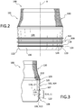
- Figs. 7-9 show an adjustable seal system 500 according to another embodiment comprising a seal component 501.
- the seal component 501 defines a body 502 forming an inner surface 503 arranged to engage with a liner body.
- the body 502 includes an upper section 504 and a lower section 506.
- a seal element 508 is attached to the outer surface 505 of the seal component 501 and arranged for engagement with an interior surface of a socket.
- the seal element 508 defines a socket sealing portion 514 arranged to create a seal or attachment between the seal component 501 and the interior surface of the socket that provides resistance to axial and/or rotational movement between the seal component 501 and the socket during use.
- the inner surface 503 of the body 502 defines a liner sealing portion 516 extending in a proximal direction from an end 507 of the socket sealing portion 514 on the body 502 comprising a connection point 513 between the body 502 and the seal element 508.
- the liner sealing portion 516 is configured to provide a sealing interface between the inner surface 503 of the body 502 and the outer surface of the prosthetic liner.
- the socket sealing portion 514 defines a sealing length L9 that at least in part defines the amount of traction between the seal component 501 and the interior surface of the socket.
- the liner sealing portion 516 defines a sealing length L10 that at least in part defines the amount of traction between the outer surface of the prosthetic liner and the inner surface 503 of the seal component 501.
- the sealing length L10 can be defined between a proximal edge on the body 502 and the connection point 513.
- the proximal edge can define an upper end 510 of the body 502.
- the liner sealing portion 516 and the socket sealing portion 514 are defined on different parts of the seal component 501.
- the liner sealing portion 516 is defined along the body 502 proximal to the connection point 513
- socket sealing portion 514 is defined on a member other than the body 502.
- the seal element 508 can comprise a member cantilevered from the connection point 513 on the body and separated from the body 502 by a variable space 530. The seal element 508 can thus freely flex relative to the body 502, and the liner sealing portion 516 and the socket sealing portion 514 are separated by the variable space 530.
- the sealing length L10 and/or position of the liner sealing portion 516 is selectively configured in relation to the socket sealing portion 514 to vary the traction at the inner and outer surfaces 503, 505 of the seal component 501.
- the sealing length L10 of the liner sealing portion 516 can be between 25 mm and about 35 mm (e.g., about 30 mm). This provides an amount of traction along the inner surface 503 of the seal component 501 that can substantially maintain the position of the seal component 501 on a prosthetic liner when a typical amount of traction for suspending the socket is present along the socket sealing portion 514, reducing the likelihood of undesirable movement or migration of the seal component 501 between the prosthetic liner and the socket, and improving reliability of the seal component 501.
- the sealing length of the liner sealing portion 516 is also not too short to generate pressure points on a residual limb, improving comfort of the seal component 501.
- the sealing length L10 of the liner sealing portion 516 can be between about 30 mm and 45 mm, between about 33 mm and 42 mm, or between about 35 mm and about 40 mm (e.g., about 39 mm).
- the sealing length L9 can be between about 20 mm and about 34 mm, about 22 mm and about 30 mm, or about 25 mm and about 28 mm (e.g., about 27 mm). It will be appreciated that the sealing lengths L9, L10 can be greater or smaller.
- the seal element 508 can be configured to vary the amount of traction along the socket sealing portion 514.
- the seal element 508 has a radially outermost portion, peak, or seal lip 524 arranged generally concentric with the upper portion 504.
- a lower segment 520 extends outwardly and in some embodiments conically from the connection point 513 to the seal lip 524.
- An upper segment 518 extends inwardly from the seal lip 524 toward the upper portion 504 of the body 502.
- a variable space 530 is defined between the body 502 and the upper segment 518 such that the seal element 508 is arranged to be compressed against a body profile 522 of the upper portion 504 when the seal component 501 is inserted in a socket.
- a flap 532 extends from the upper segment 518 and may be oriented generally parallel with the upper portion 504 and is spaced from the upper portion 504 by the variable space 530. It will be appreciated that socket sealing portion 514 can move relative to the liner sealing portion 516 to compensate for volume changes in the residual limb.
- the lower segment 520 defines at least one radial seal 532, 534 that, in combination with the seal lip 524, are arranged to maintain connection with an interior socket wall, thereby creating a seal between the seal component 501 and the socket.
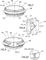
- the body profile 522 defines one or more raised portions 540 radially positioned between the seal element 508 and the body 502.
- the one or more raised portions 540 are radially positioned between the seal element 508 and the upper portion 504 and are sized and configured to create channels for airflow between the upper portion 504 and the seal element 508 during use.
- the one or more raised portions 540 can be configured such that when the seal element 508 is compressed against the body 502 during donning or loading of the prosthetic liner within the socket, closing the variable space 530 toward the body profile 522, the seal element 508 engages with the one or more raised portions 540 before reaching the body profile 522, maintaining at least a portion of the seal element 508 a distance from the body profile 522.
- This distancing or spacing of the seal element 508 from the body profile 522 provided by the raised portions 540 can create channels between the body 502 and the seal element 508 for permitting airflow therebetween. This advantageously reduces the risk of the seal element 508 sticking or becoming stuck on the body profile 522, which can undesirably restrict movement of the seal element 508 relative to the body 502 and can compromise the seal formed by the seal element 508 against the interior surface of the socket, especially during use of the prosthesis, such as a leg or foot.
- the one or more raised portions 540 can thus help increase the amount of traction along the socket sealing portion 514 and/or improve the reliability of the seal formed by the seal element 508 against the interior surface of the socket. It will be appreciated that the channels formed by the raised portions 540 between the body profile 522 and the seal element 508 can be around and/or between the one or more raised portions 540.
- the one or more raised portions 540 can also provide rotation control between the seal element 508 and the body 502, reducing the likelihood of undesirable rotational issues.
- the one or more raised portions 540 can be configured to frictionally or mechanically grip the inner side of the seal element 508 to limit relative rotation between the seal element 508 and the body 502.
- the one or more raised portions 540 can define a variety of shapes such as bubble, dome, arcuate, semi-hemispherical, square, and other available shapes that may be molded on the body 502.
- the one or more raised portions 540 comprise a single protrusion on the body profile 522.
- the one or more raised portions 540 can comprise three linear protrusions 540A, 540B, and 540C as shown in Fig. 10 or any other suitable number or shape of raised portions.
- the one or more raised portions 540 can extend generally parallel to an axis C and/or obliquely relative to the axis C.
- the raised portions 540 can be comprise linear protrusions, curved protrusions, or both.
- the raised portions 540 can comprise coil protrusions or can extend in a cross-hatch or mesh pattern between the seal element 508 and the body 502.
- the raised portions 540 can extend along the entirety or part of the height of the body 502. For instance, the raised portions 540 can define a length generally corresponding to the flap 532. The raised portions 540 can extend downwardly from the top or proximal edge 510 of the body 502. It will be appreciated that any suitable seal component of the present disclosure may optionally include one or more raised portions 540 as described herein.
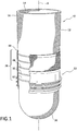
- Figs. 11 - 13 show yet another embodiment of an adjustable seal system 700 comprising a seal component 701 including a body 702 forming an inner surface 703 extending about an axis E and arranged to abut an outer surface of a liner body (e.g., liner body 12).
- the body 702 includes an upper section 704 and a lower section 706.
- the upper portion 704 is arranged to be generally concentric with the liner body and can have a substantially uniform diameter along its length of height.
- the lower section 706 defines a curvature 712 toward its lower end that decreases an inner diameter of the seal component 701. This curvature 712 allows the lower end to compress against the liner body when the seal component 701 is donned thereon, advantageously helping to minimize unwanted relative movement between the seal component 701 and the liner body.
- a plurality of seal elements 708 are formed along an outer surface 705 of the body 702.
- the seal elements 708 protrude radially outward from a body profile 722 and are arranged for engagement with a socket wall.
- the seal elements 708 are shown comprising five seal rings arranged for deflection and are axially spaced along the body profile 722 but can include any suitable number and/or structure of seal elements.
- the seal elements 708 form a socket sealing portion 714 for sealing the sealing component 701 to a socket and the inner surface 703 defines a liner sealing portion 716 that provides a sealing interface between the seal component 701 and the liner body.
- the liner sealing portion 716 and the socket sealing portion 714 are defined on different parts of the seal component 701.
- the socket sealing portion 714 is defined along the body profile 722 and the liner sealing portion 716 is defined on a separate interior wall 740 having an upper free end 745 and a lower end 747 connected to the lower section 706 on the inner surface 703 of the body 702.
- the liner sealing portion 716 is defined along the radial inner surface of the interior wall 740.
- the lower end 747 of the interior wall 740 can comprise an end 707 of the socket sealing portion 714.
- a variable space 742 is defined between the body 702 and the interior wall 740 such that the interior wall 740 is arranged to be compressed against the body 702 when the seal component 701 is donned on a prosthetic liner filling, reducing, or eliminating variable space 742.
- the interior wall 740 can thus freely move or pivot relative to the body 702, and the liner sealing portion 716 and the socket sealing portion 714 are separated by the variable space 742. This reduces the likelihood of undesirable interference between the socket sealing portion 714 and the liner sealing portion 716 and allows for traction to be generated along the socket sealing portion 714, without directly affecting the strength or operation of the traction generated along the liner sealing portion 716.
- the socket sealing portion 714 defines a sealing length L11 that at least in part defines the amount of traction between the seal component 701 and the interior surface of the socket.
- the liner sealing portion 716 defines a sealing length L12 that at least in part defines the amount of traction between the seal component 701 and the outer surface of the prosthetic liner.
- the sealing length L12 can be defined between an end 707 of the socket sealing portion 714 and a proximal edge on the body 702.
- the proximal edge on the body 702 can comprise the upper free end 745 of the interior wall 740.
- the sealing length L11 of the socket sealing portion 714 can be between about 60 mm and 80 mm, about 65 mm and 75 mm, or about 67 mm and 72 mm (e.g., 70 mm). This greater distance increases the area of the sealing interface between the seal component 701 and the socket, which, in turn, can more evenly distribute traction and is less likely to strangle, cut off circulation in, or otherwise create discomfort in a residual limb.
- the sealing length L12 and/or the position of the liner sealing portion 716 is selectively configured in relation to the socket sealing portion 714 to vary the traction at the inner and outer surfaces 703, 705 of the seal component 701.
- the sealing length of the liner sealing portion 716 can be between about 25 mm and about 35 mm.
- This configuration of the liner sealing portion 716 can provide an amount of traction along the inner surface 703 of the seal component 701 that is sufficient to substantially maintain the position of the seal component 701 on a prosthetic liner when a typical amount of traction for suspending the socket is generated along the socket sealing portion 714, reducing the likelihood of movement of the seal component 701 between the prosthetic liner and the socket, and improving reliability of the seal component 201.
- the seal component 701 can better compensate for volume changes in the residual limb to improve suspension of the adjustable seal component 701 over known adjustable seal components.
- an open-ended prosthetic sock 750 or fabric sleeve having a distal portion can be positioned within the variable space 742 between the interior wall 740 and the inner surface 702 as shown in Fig. 13 .
- This beneficially can provide cushioning and help locate the seal component 701 on the prosthetic liner to improve ease of use over known adjustable seal components.
- the compression of the interior wall 740 against the inner surface 702 can secure the prosthetic sock 750 within the variable space 742, helping to maintain the prosthetic sock 750 in a proper position during use.
- any seal component of the present disclosure may optionally include an interior wall and/or open-ended prosthetic sock as described herein.
- the socket sealing portion and/or liner sealing portion may be decided according to the needs of the user, and sensitive areas may be avoided.
- the adjustable seal components can be arranged to engage a liner body without any seal bands.
- the adjustable seal components can be arranged to engage with and secure on a liner comprising a textile free liner.
- the adjustable seal embodiments may enable improved durability by having better abrasion resistance due to the versatility in placement of the seal component and its separate yet non-permanent attachment to the liner.
- an adjustable seal is provided that can be removably mounted on a prosthetic liner and has a liner sealing portion configured to cooperate with a socket sealing portion to securely mount the adjustable seal on the prosthetic liner and to securely suspend the prosthetic liner and residual limb within the socket.
- the liner sealing portion is further advantageously configured to have a length sufficient to avoid unwanted migration of the adjustable seal without creation pressure points, discomfort, or difficulty in donning and doffing the adjustable seal component.
Landscapes
- Health & Medical Sciences (AREA)
- Cardiology (AREA)
- Oral & Maxillofacial Surgery (AREA)
- Transplantation (AREA)
- Engineering & Computer Science (AREA)
- Biomedical Technology (AREA)
- Heart & Thoracic Surgery (AREA)
- Vascular Medicine (AREA)
- Life Sciences & Earth Sciences (AREA)
- Animal Behavior & Ethology (AREA)
- General Health & Medical Sciences (AREA)
- Public Health (AREA)
- Veterinary Medicine (AREA)
- Prostheses (AREA)
Claims (15)
- Einstellbares Dichtungssystem (100) zum Bereitstellen einer Schnittstelle zwischen einem Stumpf und einem Prothesenschaft, wobei das einstellbare Dichtungssystem (100) umfasst:eine Dichtungskomponente (101), die zur abnehmbaren Befestigung an einer Außenfläche eines Prothesenfutters (10) angeordnet ist, wobei die Dichtungskomponente (101) umfasst:einen Körper (102) mit offenen oberen und unteren Enden und einer Innenfläche (103), die eine Öffnung durch sie hindurch definiert, und eine Außenfläche (105) gegenüber der Innenfläche (103);einen Schaftdichtungsabschnitt (114) an der Außenfläche (105) des Körpers (102), der so angeordnet ist, dass er in eine Innenfläche des Prothesenschaftes eingreift und mit dieser eine luftdichte Abdichtung bildet; und einen Futterdichtungsabschnitt (116) auf der die Innenfläche (103) des Körpers (102) so angeordnet ist, dass er reibschlüssig mit der Außenfläche des Prothesenfutters (10) in Eingriff kommt und abdichtet, wobei der Futterdichtungsabschnitt (116) eine Dichtungslänge (L2) definiert, die sich in einer proximalen Richtung von einem Ende (107) des Schaftdichtungsabschnitts (114) erstreckt und an einer proximalen Kante (110) am Körper (102) endet,dadurch gekennzeichnet, dassdie Dichtungslänge (L2) des Futterdichtungsabschnitts (116) zwischen etwa 25 mm und etwa 35 mm beträgt und im Verhältnis zu dem Schaftdichtungsabschnitt (114) gewählt wird, um die Zugkräfte an den Innen- und Außenflächen (103, 105) des Körpers (102) der Dichtungskomponente (101) zu variieren.
- Einstellbares Dichtungssystem (100) nach Anspruch 1, dadurch gekennzeichnet, dass die Dichtungslänge (L2) des Futterdichtungsabschnitts (116) etwa 30 mm beträgt.
- Einstellbares Dichtungssystem (100) nach einem der vorhergehenden Ansprüche, dadurch gekennzeichnet, dass die Dichtungslänge (L2) des Futterdichtungsabschnitts (116) zwischen etwa 1,2 und 1,3 mal größer ist als eine Dichtungslänge (L1) des Schaftdichtungsabschnitts (114), die zwischen dem Ende (107) des Schaftdichtungsabschnitts (114), das ein proximales Ende und ein distales Ende des Schaftdichtungsabschnitts (114) umfasst, definiert ist.
- Einstellbares Dichtungssystem (100) nach einem der vorhergehenden Ansprüche, dadurch gekennzeichnet, dass der Schaftdichtungsabschnitt (114) eine Vielzahl von Dichtungselementen (108) umfasst, die auf der Außenfläche (105) des Körpers (102) ausgebildet sind.
- Einstellbares Dichtungssystem (100) nach Anspruch 4, dadurch gekennzeichnet, dass es eine Vielzahl von Greifringen (128) umfasst, die an dem Körper (102) ausgebildet sind und sich in Umfangsrichtung um die Außenfläche (105) des Körpers (102) zwischen den Dichtungselementen (128) erstrecken, wobei die Vielzahl von Greifringen (128) so konfiguriert ist, dass sie die Traktion zwischen der Dichtungskomponente (101) und der Innenfläche des Prothesenschaftes verbessern.
- Einstellbares Dichtungssystem (100) nach Anspruch 1, dadurch gekennzeichnet, dass der Schaftdichtungsabschnitt (114) mindestens ein Dichtungselement (508) umfasst, das von einem Verbindungspunkt (513) auskragt, der das mindestens eine Dichtungselement (508) mit der Außenfläche (505) des Körpers (502) verbindet.
- Einstellbares Dichtungssystem (100) nach Anspruch 6, dadurch gekennzeichnet, dass der Verbindungspunkt (513) das Ende (507) des Schaftdichtungsabschnitts (514) an der Außenfläche (505) des Körpers (502) umfasst, so dass sich der Futterdichtungsabschnitt (516) an der Innenfläche (503) des Körpers (502) zwischen dem proximalen Rand (510) des Körpers (502) und dem Verbindungspunkt (513) erstreckt.
- Einstellbares Dichtungssystem (100) nach Anspruch 1, dadurch gekennzeichnet, dass der Dichtungsabschnitt (716) eine Innenwand (740) aufweist, die zumindest einen Teil der Innenfläche (703) des Körpers (702) bildet, und der proximale Rand am Körper ein oberes freies Endes (745) der Innenwand (740) aufweist.
- Einstellbares Dichtungssystem (100) nach Anspruch 1, dadurch gekennzeichnet, dass der Dichtungsabschnitt (514) mindestens ein Dichtungselement (508) aufweist, das um einen Abstand von der Außenfläche (505) des Körpers (502) der Dichtungskomponente (501) beabstandet ist.
- Einstellbares Dichtungssystem (100) nach Anspruch 9, dadurch gekennzeichnet, dass der Körper (502) einen oder mehrere erhabene Abschnitte (540) definiert, die radial zwischen dem mindestens einen Dichtungselement (508) und einem Körperprofil (522) der Außenfläche (505) des Körpers (502) angeordnet sind, wobei der eine oder die mehreren erhabenen Abschnitte (540) so konfiguriert sind, dass sie Kanäle für den Luftstrom zwischen dem mindestens einen Dichtungselement (508) und dem Körperprofil (522) bilden.
- Einstellbares Dichtungssystem (100) nach Anspruch 10, dadurch gekennzeichnet, dass der eine oder die mehreren erhabenen Abschnitte (540) einen linearen Vorsprung umfassen, der sich in einer Richtung zwischen dem offenen oberen und unteren Ende des Körpers (502) erstreckt.
- Einstellbares Dichtungssystem (100) nach Anspruch 10, dadurch gekennzeichnet, dass der eine oder die mehreren erhabenen Abschnitte (540) eine Vielzahl von linearen Vorsprüngen umfassen, die sich in einer Richtung zwischen dem offenen oberen und unteren Enden des Körpers (502) erstrecken.
- Einstellbares Dichtungssystem (100) nach Anspruch 10, dadurch gekennzeichnet, dass der eine oder die mehreren erhabenen Abschnitte (540) eine Mehrzahl von linearen Vorsprüngen umfassen, die sich in einer schrägen Richtung zwischen den offenen oberen und unteren Ende des Körpers (502) erstrecken.
- Einstellbares Dichtungssystem (100) nach Anspruch 1, dadurch gekennzeichnet, dass die Innenfläche (703) des Körpers (702) eine Innenwand (740) aufweist, die mit einem unteren Abschnitt des Körpers (702) verbunden ist und einen variablen Raum (742) zwischen der Innenwand (740) und dem Körper (702) definiert
- Einstellbares Dichtungssystem (100) nach Anspruch 14, dadurch gekennzeichnet, dass ein distaler Teil einer Prothesensocke (750) in dem variablen Raum (742) zwischen dem Körper (702) und dem Körper (702) positionierbar und befestigbar ist.
Applications Claiming Priority (2)
| Application Number | Priority Date | Filing Date | Title |
|---|---|---|---|
| US201762591502P | 2017-11-28 | 2017-11-28 | |
| PCT/US2018/062267 WO2019108460A1 (en) | 2017-11-28 | 2018-11-21 | Adjustable seal system, seal component and method for using the same |
Publications (2)
| Publication Number | Publication Date |
|---|---|
| EP3716919A1 EP3716919A1 (de) | 2020-10-07 |
| EP3716919B1 true EP3716919B1 (de) | 2021-11-03 |
Family
ID=64661515
Family Applications (1)
| Application Number | Title | Priority Date | Filing Date |
|---|---|---|---|
| EP18815911.5A Active EP3716919B1 (de) | 2017-11-28 | 2018-11-21 | Einstellbares dichtungssystem und eine dichtungskomponte zwischen einem residuellen glieden und eine prothesenpfannen |
Country Status (3)
| Country | Link |
|---|---|
| US (2) | US11510793B2 (de) |
| EP (1) | EP3716919B1 (de) |
| WO (1) | WO2019108460A1 (de) |
Families Citing this family (1)
| Publication number | Priority date | Publication date | Assignee | Title |
|---|---|---|---|---|
| US8956422B2 (en) * | 2011-08-22 | 2015-02-17 | Ossur Hf | Suspension liner with seal component |
Family Cites Families (181)
| Publication number | Priority date | Publication date | Assignee | Title |
|---|---|---|---|---|
| US980457A (en) | 1910-01-13 | 1911-01-03 | Justin Kay Toles | Artificial limb. |
| US1398824A (en) | 1921-03-01 | 1921-11-29 | Abrams Joseph | Artificial-limb socket |
| GB267988A (en) | 1925-09-18 | 1927-03-18 | Charles Albert Blatchford | Improvements in or connected with artificial limbs |
| GB269606A (en) | 1925-11-13 | 1927-04-13 | Charles Albert Blatchford | Improvements in or connected with artificial limbs |
| GB263377A (en) | 1926-04-21 | 1926-12-30 | Thomas Bryant Smith | Improvements in or relating to artificial limb sockets |
| DE484363C (de) | 1928-05-22 | 1929-10-14 | Eisenwerk | An- und Ablegevorrichtung fuer Tiegeldruckpressen |
| US1893853A (en) | 1931-12-15 | 1933-01-10 | Amos E Tullis | Artificial limb |
| US2244871A (en) | 1939-03-09 | 1941-06-10 | Kleinert I B Rubber Co | Waterproof protective device |
| DE745981C (de) | 1940-09-21 | 1944-05-22 | Alois Geisen | Kuenstliches Bein mit einer durch Saugwirkung auf dem Beinstumpf zu befestigenden Huelse |
| US2325656A (en) | 1940-11-28 | 1943-08-03 | United Shoe Machinery Corp | Reinforcing shoe parts |
| US2464443A (en) | 1947-11-17 | 1949-03-15 | Charles V Ganoe | Prosthetic limb socket for amputees |
| US2530285A (en) | 1947-12-11 | 1950-11-14 | John G Catranis | Artificial leg |
| US2533404A (en) | 1948-08-13 | 1950-12-12 | Sharp Oscar | Artificial limb and valve therefor |
| DE813190C (de) | 1948-10-02 | 1951-09-10 | Franz Clouth | Saugprothese |
| BE505683A (de) | 1950-09-19 | |||
| US2689351A (en) | 1951-10-06 | 1954-09-21 | Frank A Schindler | Method of forming stump sockets |
| US2671225A (en) | 1951-11-05 | 1954-03-09 | Bardach Schoene Company Inc | Artificial limb stump socket |
| BE551068A (de) | 1955-09-16 | |||
| US2808593A (en) | 1956-02-07 | 1957-10-08 | Andersen Algot | Artificial limbs |
| DE1795809U (de) | 1958-08-23 | 1959-09-17 | Hildegard Seitz | Orthopaedische bein- oder armprothese. |
| US3393407A (en) | 1965-12-16 | 1968-07-23 | Edward J. Kandel | Artificial limb with end-bearing socket and method of making |
| US3587572A (en) | 1968-07-17 | 1971-06-28 | Michael Evans | Knee brace |
| DE2060239C3 (de) | 1970-12-08 | 1974-05-09 | Surerus, Walter, Dr.Med., 7016 Gerlingen | Prothesenschaft mit ringförmiger Stützeinlage, insbesondere für Beinprothesen |
| US3671980A (en) | 1971-02-19 | 1972-06-27 | Lincoln F Baird | Fluid pressure clamp for prosthetic appliance |
| DE2127269A1 (de) | 1971-06-02 | 1972-12-14 | Helfrecht, Manfred, 8591 Poppenreuth | Einlage fur Kunstgheder |
| US3947897A (en) | 1975-03-17 | 1976-04-06 | Owens Lester J | Apparatus for connecting a prosthesis to a bone |
| DE2540138C3 (de) | 1975-09-09 | 1978-03-02 | Walter Dr.Med. 7016 Gerlingen Surerus | Ringförmige Stützeinlage für einen Prothesenschaft |
| DE2544446C3 (de) | 1975-10-04 | 1979-12-20 | Willy Dipl.-Ing. 6602 Dudweiler Meyer | Prothese für einen Unterschenkel oder Unterarm |
| SE410271B (sv) | 1976-04-28 | 1979-10-08 | Landstingens Inkopscentral | Protes for amputerade underben med ingaende mellanlegg |
| FR2420335A1 (fr) | 1978-03-21 | 1979-10-19 | Proteor Sa | Dispositif d'adaptation pour appareils orthopediques, procede pour sa fabrication et son application a la realisation d'emboitures de protheses de membres |
| US4215679A (en) | 1978-09-06 | 1980-08-05 | Rustin Jesse L | Circulation assist device for body extremities |
| US4347204A (en) | 1978-12-19 | 1982-08-31 | Olympus Optical Co., Ltd. | Flexible tube and method of manufacturing same |
| US4311317A (en) | 1979-08-20 | 1982-01-19 | Bartels Harold U | Lip and radial seal |
| AT369978B (de) | 1980-02-19 | 1983-02-25 | Ipos Gmbh & Co Kg | Verfahren zur herstellung von prothesenschaeften und hiernach hergestellter prothesenschaft |
| GB2069847B (en) | 1980-02-22 | 1985-01-23 | Blatchford & Sons Ltd | Artificial limb |
| US4319413A (en) | 1980-04-11 | 1982-03-16 | Pruf-und Forschungsinstitut fur die Schuhherstellung | Seam construction, particularly for heel portions of shoes and method of effecting the same |
| GB2087727B (en) | 1980-10-14 | 1984-01-25 | Steeper Hugh Ltd | Manufacture of a prosthetics socket |
| US4474573A (en) | 1982-02-24 | 1984-10-02 | Detty Garnett E | Knee sleeve |
| DE3221920A1 (de) | 1982-06-11 | 1983-04-07 | Surerus, Walter, Dr., 7016 Gerlingen | Schaft einer prothese |
| FR2539616A1 (fr) | 1983-01-25 | 1984-07-27 | Renaissance Sanitaire | Emboiture souple utilisee pour la prothetisation d'un ampute femoral |
| US4635626A (en) | 1984-11-16 | 1987-01-13 | Max Lerman | Prosthetic stockings |
| US4738249A (en) | 1985-03-01 | 1988-04-19 | The Procter & Gamble Company | Method and apparatus for augmenting blood circulation |
| DE3508919A1 (de) | 1985-03-13 | 1986-09-18 | Surerus, Walter, Dr.Med., 7016 Gerlingen | Schaft einer prothese |
| SE454943B (sv) | 1986-06-26 | 1988-06-13 | Ossur Hf | Hylselement, speciellt for amputationsstump |
| JP2637076B2 (ja) | 1986-07-21 | 1997-08-06 | 三井石油化学工業 株式会社 | プロピレンブロツク共重合体の製法 |
| US4767735A (en) | 1987-02-02 | 1988-08-30 | Cosden Technology, Inc. | Catalyst pretreatment process |
| US5122583A (en) | 1987-02-02 | 1992-06-16 | Fina Technology, Inc. | Efficiency of a pre-polymerized catalyst |
| DE3752331T2 (de) | 1987-02-02 | 2001-09-20 | Fina Technology, Inc. | Verfahren zur Verbesserung der Effektivität eines prepolymerisierten Katalysators |
| GB8802933D0 (en) | 1988-02-09 | 1988-03-09 | Porvair Ltd | Porelle/stretchable fabric composite & socks therefrom |
| US5007937A (en) | 1988-03-31 | 1991-04-16 | New York University Medical Center | Structure for enhanced retention of artificial limbs and method of fabrication |
| US4908037A (en) | 1988-09-16 | 1990-03-13 | Ross Michael R | Suspension prosthetic sleeve for rigorous activity |
| US4885828A (en) | 1988-11-14 | 1989-12-12 | Lear Siegler Seating Corp. | Method and apparatus for positioning fabric covers on a foam cushion |
| US5571208A (en) | 1990-07-13 | 1996-11-05 | Caspers; Carl A. | Reinforced prosthetic polyurethane hypobaric sleeve |
| US5376129A (en) | 1990-12-04 | 1994-12-27 | Board Of Regents, The University Of Texas System | Method and apparatus for making prosthetic socket preforms, prosthetic sockets, and socket attachment component |
| US5108456A (en) | 1991-01-28 | 1992-04-28 | Coonan Iii Thomas J | Prosthetic appliance |
| US5139523A (en) | 1991-07-12 | 1992-08-18 | Paton Matthew T | Artificial limb socket apparatus |
| US5163965A (en) | 1991-07-29 | 1992-11-17 | Becker Orthopedic Appliance Company | Prosthetic attachment device and method |
| US5169161A (en) | 1991-09-19 | 1992-12-08 | Hail Mary Rubber Co., Inc. | Symmetrical gasket for pipe joints |
| US5387245A (en) | 1991-12-23 | 1995-02-07 | Fay; John N. | Inflatable prosthesis liner |
| JPH0623406A (ja) | 1992-07-08 | 1994-02-01 | Kawasaki Steel Corp | 鋼片の連続熱間圧延方法 |
| US5226918A (en) | 1992-07-13 | 1993-07-13 | Howard Silagy | Prosthesis with adjustable fitting clearance |
| US5314496A (en) | 1992-12-31 | 1994-05-24 | Harris Bertram H | Stump sock arrangement |
| US5376131A (en) | 1993-07-01 | 1994-12-27 | Manhasset Orthotics And Prosthetics, Ltd. | Suction socket for artificial limb |
| JP3984304B2 (ja) | 1993-08-18 | 2007-10-03 | 三井化学株式会社 | オレフィン重合用触媒、これを用いるプロピレン系重合体の製造方法 |
| JPH0822295B2 (ja) | 1993-12-03 | 1996-03-06 | 株式会社奈良義肢 | 義足または義手の装着構造 |
| KR0150433B1 (ko) | 1994-03-18 | 1998-10-15 | 발레 메이커즈, 인코포레이티드 | 분리형 구두창 및 중간부분 보강부로 이루어진 신발 |
| DE9419208U1 (de) | 1994-11-30 | 1995-01-26 | Carstens, Felix, 67433 Neustadt | Künstliches Glied |
| US5728167A (en) | 1995-01-11 | 1998-03-17 | Lohmann; Klaus H. | Prosthetic sock for reducing movement between residual limb and prosthesis |
| US5593454A (en) | 1995-01-12 | 1997-01-14 | Helmy; Nashat N. | Artificial limb mounting apparatus |
| US5571209A (en) | 1995-01-27 | 1996-11-05 | Flo-Tech Orthotic & Prosthetic Systems, Inc. | Post-operative protective prosthesis |
| US5830237A (en) | 1996-03-05 | 1998-11-03 | Ohio Willow Wood Company | Gel and cushioning devices |
| US5735906A (en) | 1995-07-26 | 1998-04-07 | Caspers; Carl A. | Hypobarically-controlled artificial limb with detents for amputees |
| US5549709A (en) | 1995-07-26 | 1996-08-27 | Caspers; Carl A. | Hypobarically-Controlled artificial limb for amputees |
| US5702489A (en) | 1995-08-18 | 1997-12-30 | Materials Engineering And Development, Inc. | Valve assembly for a prosthetic limb |
| US6287345B1 (en) | 1995-08-18 | 2001-09-11 | The Ohio Willow Wood Company | Valve assembly for a prosthetic limb |
| ES2152353T3 (es) | 1995-09-08 | 2001-02-01 | Bock Orthopaed Ind | Protesis de pierna. |
| US5658353A (en) | 1995-10-31 | 1997-08-19 | Layton; Harry W. | Method for donning or doffing an artificial limb |
| EP0803343B1 (de) | 1995-11-09 | 2005-09-07 | Ashimori Industry Co., Ltd. | Auskleidung von leitungen und verfahren zu deren herstellung |
| US5718925A (en) | 1995-11-15 | 1998-02-17 | Ossur Hf. | Apparatus for making a prosthesis socket |
| US5888216A (en) | 1996-03-18 | 1999-03-30 | Haberman; Louis J. | Prosthesis liner for below-knee amputees |
| EP0955964B1 (de) | 1996-07-31 | 2006-10-11 | Ohio Willow Wood Company | Gel und polster-vorrichtung |
| US6964688B1 (en) | 1996-07-31 | 2005-11-15 | Ohio Willow Wood Company | Tube sock-shaped covering |
| US6171431B1 (en) | 1996-08-27 | 2001-01-09 | Joseph E. Gallagher, Jr. | Welded fabric seams with inner and outer tabs |
| JP2740503B2 (ja) | 1996-08-28 | 1998-04-15 | 三井化学株式会社 | α−オレフインの重合方法 |
| US5728168A (en) | 1996-10-29 | 1998-03-17 | Alps South Corporation | Elastomer reinforcement of an elastomer interface membr for residual limb of an amputee |
| US5888230A (en) | 1997-04-01 | 1999-03-30 | Helmy; Nashat N. | Modular liner for limb stump prosthesis |
| US6918936B2 (en) | 1997-04-29 | 2005-07-19 | Kennet Hellberg | Thermoplastic liner blank |
| US5980577A (en) | 1997-05-01 | 1999-11-09 | Radis; Vasilis | Protective item supporting an appendage |
| US6136039A (en) | 1997-05-06 | 2000-10-24 | Ossur Hf | Dual durometer silicone liner for prosthesis |
| CN100406476C (zh) | 1998-03-23 | 2008-07-30 | 蒙特尔技术有限公司 | 用于烯烃聚合的预聚合催化剂组分 |
| US6149691A (en) | 1998-06-26 | 2000-11-21 | Fay; John N. | Self-inflating socket having encased gel |
| US6368357B1 (en) | 1998-10-16 | 2002-04-09 | Aircast, Inc. | Therapeutic device for amputees |
| US6361568B1 (en) | 1999-02-09 | 2002-03-26 | Alps South Corporation | Prosthetic sleeve with air outlet valve |
| CN1144573C (zh) | 1999-03-01 | 2004-04-07 | 奥苏尔公司 | 由具不同弹性劲度的弹性织物部分形成的矫形或修复套筒 |
| US6926742B2 (en) | 1999-06-03 | 2005-08-09 | Otto Bock Healthcare Lp | Plate/socket attachment for artificial limb vacuum pump |
| WO2000074611A2 (en) | 1999-06-03 | 2000-12-14 | Caspers-Schneider Technologies,Inc. | Hypobarically-controlled socket for artificial limb |
| US6726726B2 (en) | 1999-06-03 | 2004-04-27 | Otto Bock Healthcare Lp | Vacuum apparatus and method for managing residual limb volume in an artificial limb |
| US7922775B2 (en) | 1999-06-03 | 2011-04-12 | Otto Bock Healthcare Lp | Pulsating pressure chamber and method for fluid management |
| US20010016781A1 (en) | 1999-06-03 | 2001-08-23 | Caspers Carl A. | Osmotic membrane and vacuum system for artificial limb |
| US20040098136A1 (en) | 1999-06-03 | 2004-05-20 | Caspers Carl A. | Socket liner for artificial limb with permanent attachment to socket |
| US6645253B2 (en) | 1999-06-03 | 2003-11-11 | Carl A. Caspers | Vacuum pump and shock absorber for artificial limb |
| US6508842B1 (en) | 1999-06-03 | 2003-01-21 | Barbara J. Caspers | Socket liner for artificial limb |
| US6554868B1 (en) | 1999-06-03 | 2003-04-29 | Carl A. Caspers | Vacuum pump and shock absorber for artificial limb |
| US6231617B1 (en) | 1999-07-14 | 2001-05-15 | John N. Fay | Prosthetic liner having longitudinal inelasticity |
| JP4177937B2 (ja) | 1999-08-18 | 2008-11-05 | 日本ポリプロ株式会社 | α−オレフィン重合用触媒および重合方法 |
| US6273918B1 (en) | 1999-08-26 | 2001-08-14 | Jason R. Yuhasz | Magnetic detachment system for prosthetics |
| DE60138944D1 (de) | 2000-03-14 | 2009-07-23 | Ossur Hf | Elastisches verbundmaterial |
| CN1208034C (zh) | 2000-03-14 | 2005-06-29 | 奥苏尔公司 | 制造假体抽吸式衬套的方法 |
| RU2263489C2 (ru) | 2000-03-15 | 2005-11-10 | Оссур Хф | Устройство и способ изготовления всасывающей прокладки для протеза |
| US6585774B2 (en) | 2000-04-25 | 2003-07-01 | Simbex, Llc | Dynamic variable geometry fitting system for use with a body appliance |
| AU2001277992A1 (en) | 2000-09-27 | 2002-04-08 | Caspers-Schneider Technologies, Inc., D/B/A Tec Interface Systems | Socket liner for artificial limb |
| US6589289B2 (en) | 2000-10-04 | 2003-07-08 | Ossur Hf | Prosthetic socket and socket component assembly |
| NO313119B1 (no) | 2000-10-18 | 2002-08-12 | Dag Vilnes | Rammekonstruksjon for plane konstruksjoner |
| US20020183859A1 (en) | 2001-06-04 | 2002-12-05 | Houser Guy M. | Socket interface sleeve for a prosthetic device |
| FR2828093B1 (fr) | 2001-08-06 | 2004-06-25 | Renaissance Sanitaire | Emboiture souple pour la prothetisation d'une personne amputee du membre superieur |
| DE10142492A1 (de) | 2001-08-30 | 2003-04-03 | Carstens Orthopaedie Und Mediz | Prothesenschaft mit Dichtung |
| DE10142491B4 (de) | 2001-08-30 | 2004-10-07 | össur h.f. | Dichtanordnung mit Lippen für einen Prothesenschaft |
| US6797008B1 (en) | 2001-10-22 | 2004-09-28 | Ohio Willow Wood | System and method for securing a prosthetic limb |
| DE10164892B4 (de) | 2001-11-05 | 2009-08-27 | össur h.f. | Strumpfförmiger Liner bzw. Liner zur Verwendung mit einem becherförmigen Prothesenschaft |
| US6852269B2 (en) | 2002-03-19 | 2005-02-08 | Silipos, Inc. | Process for applying a cushion material to an article |
| US20030181989A1 (en) | 2002-03-19 | 2003-09-25 | Ssl Americas, Inc. | Cushioned liner and use with prosthetic devices |
| US6544292B1 (en) | 2002-04-08 | 2003-04-08 | Aldo A. Laghi | Prosthetic liner with integral air expulsion valve |
| DE10221100C1 (de) | 2002-05-03 | 2003-06-05 | Neuhaus Elektronik Gmbh | Elektrisch leitfähige Dichtung sowie Verfahren und Vorrichtung zu deren Herstellung |
| EP1509176B1 (de) | 2002-05-23 | 2006-08-23 | Otto Bock HealthCare, LP | Pulsierende druckkammer in einer prothetischen gliedmasse |
| US6929125B1 (en) | 2002-07-25 | 2005-08-16 | Foam Technologies, Inc. | Watertight protective carrying case |
| KR100739672B1 (ko) | 2002-09-10 | 2007-07-13 | 삼성전자주식회사 | 광정보 저장매체 및 데이터의 재생 방법 |
| CA2501488C (en) | 2002-11-01 | 2013-02-26 | Otto Bock Healthcare Lp | Pressure/temperature monitoring device for prosthetics |
| US7025793B2 (en) | 2002-12-20 | 2006-04-11 | Ossur Hf | Suspension liner with seal |
| US9877851B2 (en) * | 2002-12-20 | 2018-01-30 | Ossur Hf | Adjustable seal system, seal component and method for using the same |
| US7909884B2 (en) | 2002-12-20 | 2011-03-22 | Ossur Hf | Suspension liner system with seal |
| US8034120B2 (en) | 2002-12-20 | 2011-10-11 | Ossur Hf | Suspension liner system with seal |
| AU2004242899A1 (en) | 2003-05-29 | 2004-12-09 | Basell Poliolefine Italia S.R.L | Process for the preparation of a catalyst component and components therefrom obtained |
| WO2005000155A2 (en) | 2003-06-20 | 2005-01-06 | Ossur Hf | Prosthetic socket with self-contained vacuum reservoir |
| NL1023926C2 (nl) | 2003-07-15 | 2005-01-18 | Univ Groningen | Prothese op basis van een met vezels versterkte hydrogel en werkwijze voor het vervaardigen van de prothese en de toepassing hiervan. |
| US20050101693A1 (en) | 2003-11-06 | 2005-05-12 | Ohio Willow Wood Company | Gel and cushioning devices |
| AU2005237488B2 (en) | 2004-04-22 | 2010-02-25 | Otto Bock Healthcare Lp | Vacuum pump with shock absorption and controlled rotation for prosthetic devices |
| EP1748748B1 (de) | 2004-05-28 | 2012-10-31 | Össur hf | Prothetische oder orthotische hülle mit peripheren profilen auf der aussenseite |
| JP5138151B2 (ja) | 2004-12-21 | 2013-02-06 | 住友化学株式会社 | 予備重合済付加重合用触媒成分、付加重合用触媒および付加重合体の製造方法 |
| US20060212128A1 (en) | 2005-03-16 | 2006-09-21 | Jaems E. And Joyce E. Smith | Artificial limb assembly having microprocessor-controlled vacuum pump |
| JP2006316160A (ja) | 2005-05-12 | 2006-11-24 | Japan Polypropylene Corp | オレフィン重合用触媒の保存方法 |
| US20090069171A1 (en) | 2005-05-12 | 2009-03-12 | Japan Polypropylene Corporation | Catalysts for olefin polymerization, process for production of the catalysts, and method for preservation thereof |
| US7967869B2 (en) | 2005-06-25 | 2011-06-28 | Alfred E. Mann Foundation For Scientific Research | Method of attaching a strapless prosthetic arm |
| US7351264B2 (en) | 2005-07-27 | 2008-04-01 | Wilson Michael T | Liner for prosthesis |
| US7771487B2 (en) | 2005-08-01 | 2010-08-10 | Mantelmacher H Lee | Anti-slip attachment and drainage system for prosthetics |
| US7363778B2 (en) | 2005-08-16 | 2008-04-29 | Knit-Rite, Inc. | Seamless three-dimensional toe section for prosthetic socks and prosthetic shrinkers |
| US20070061017A1 (en) | 2005-09-09 | 2007-03-15 | Wilson Michael T | Liner for use with prosthetic devices |
| US7993413B2 (en) | 2005-09-24 | 2011-08-09 | Matt Perkins | Valve system for prosthetics |
| DE102006054891A1 (de) | 2006-11-20 | 2008-06-05 | Felix Carstens | Prothesenschaft mit aktivem Luftausstoß |
| US9259332B2 (en) | 2006-12-14 | 2016-02-16 | Lincolnshire Manufacturing, Llc | Prosthetic vacuum system |
| US9814606B2 (en) | 2006-12-14 | 2017-11-14 | Morris J. Danzig | Prosthetic vacuum system |
| US20080188949A1 (en) | 2007-02-01 | 2008-08-07 | Mackenzie Craig | Prosthetic and orthotic liners/sleeves with surfaces having a roughness or reduced coefficient of friction, and related methods |
| US8080065B2 (en) | 2007-03-05 | 2011-12-20 | Scussel Sbj Systems, Llc | Vacuum assisted prosthetic sleeve and socket utilizing a double membrane liner |
| US7927378B2 (en) | 2007-03-05 | 2011-04-19 | Scussel Sbj Systems, Llc | Vacuum assisted prosthetic sleeve and socket |
| US20080269914A1 (en) | 2007-03-19 | 2008-10-30 | Qfix Systems, Llc | Direct contact moldable low temperature thermoplastic prosthetic devices |
| EP2170229A2 (de) | 2007-08-02 | 2010-04-07 | Össur HF | Auskleidung für prothetische und orthopädische systeme |
| GB0718863D0 (en) | 2007-09-28 | 2007-11-07 | Watts Robert J | Prosthesis & residual limb cover |
| DE202007015828U1 (de) | 2007-11-13 | 2008-02-07 | Bielefeld, Thilo-Mathias | Liner für Vakuumschäfte |
| US20090182435A1 (en) | 2008-01-15 | 2009-07-16 | Engineered Silicone Products, Llc | Limb prosthesis |
| GB0801065D0 (en) | 2008-01-21 | 2008-02-27 | Blatchford & Sons Ltd | System for use with a prosthetic device |
| US20090240344A1 (en) | 2008-03-19 | 2009-09-24 | The Ohio Willow Wood Company | Multi-layer polymeric prosthetic liner |
| US7927377B2 (en) | 2008-06-09 | 2011-04-19 | Prosthetic Design, Inc. | Elevated vacuum locking system |
| US8808394B2 (en) | 2008-06-10 | 2014-08-19 | Alps South, LLC | Prosthetic liner with perspiration elimination mechanism |
| US8679194B2 (en) | 2009-01-21 | 2014-03-25 | Evolution Industries, Inc. | Expulsion liner for prosthetic or orthotic devices and associated methods |
| WO2010085336A1 (en) | 2009-01-21 | 2010-07-29 | Craig Mackenzie | Sealing sheath for prosthetic liner and related methods |
| US8206459B1 (en) | 2009-03-18 | 2012-06-26 | Rehabilitation Institute Of Chicago | Prosthetic-to-liner attachment mechanism |
| CA2759507A1 (en) | 2009-04-28 | 2010-11-11 | Empowering Engineering Technologies Corp. | Adjustable prosthesis |
| US8535389B2 (en) | 2009-09-18 | 2013-09-17 | McKinney Prosthetics | Prosthetic socket liner |
| EP2501344B1 (de) | 2009-11-17 | 2015-02-25 | Össur HF | Aufhängungsverkleidung mit mehrfachkomponentensystem |
| US9028558B2 (en) | 2009-11-17 | 2015-05-12 | Ossur Hf | Suspension liner having multiple component system |
| EP2353550A1 (de) | 2010-02-05 | 2011-08-10 | Nakamura Brace Co.,Ltd. | Element für künstliches Gliedmaß |
| JP5348593B2 (ja) | 2010-03-29 | 2013-11-20 | 株式会社啓愛義肢材料販売所 | 断端に装着したライナーの義肢ソケットへの取付構造 |
| US9248032B2 (en) | 2010-10-14 | 2016-02-02 | Ossur Hf | Suspension liner system with distensible seal |
| WO2012142627A2 (en) * | 2011-04-14 | 2012-10-18 | The Ohio Willow Wood Company | Prosthetic socket sealing system and method |
| US9155636B1 (en) * | 2011-06-01 | 2015-10-13 | Ray Fikes | Prosthetic socket liner |
| JP5918486B2 (ja) | 2011-07-06 | 2016-05-18 | サンアロマー株式会社 | α−オレフィン重合方法 |
| US8956422B2 (en) * | 2011-08-22 | 2015-02-17 | Ossur Hf | Suspension liner with seal component |
| DE102012017214A1 (de) | 2012-08-31 | 2014-05-15 | Otto Bock Healthcare Gmbh | Prothesenliner und Prothesenschaftsystem mit Prothesenliner und Prothesenschaft |
| DE102013010371B4 (de) | 2013-06-21 | 2015-02-05 | Medi Gmbh & Co. Kg | Anordnung zum Überziehen über einen Gliedmaßenstumpf zur Fixierung eines Prothesenschafts |
| AU2014348447B2 (en) | 2013-11-15 | 2019-03-14 | Ossur Iceland Ehf | Adjustable seal system, seal component |
| WO2017066038A1 (en) | 2015-10-15 | 2017-04-20 | Ossur Iceland Ehf | Adjustable seal system |
| EP3238667B1 (de) | 2016-04-25 | 2018-10-10 | Össur Iceland EHF | Liner zum überziehen über einen gliedmassenstumpf |
-
2018
- 2018-11-21 EP EP18815911.5A patent/EP3716919B1/de active Active
- 2018-11-21 WO PCT/US2018/062267 patent/WO2019108460A1/en not_active Ceased
- 2018-11-21 US US16/198,427 patent/US11510793B2/en active Active
-
2022
- 2022-10-20 US US17/969,901 patent/US20230042794A1/en active Pending
Also Published As
| Publication number | Publication date |
|---|---|
| WO2019108460A1 (en) | 2019-06-06 |
| US20190159911A1 (en) | 2019-05-30 |
| EP3716919A1 (de) | 2020-10-07 |
| US20230042794A1 (en) | 2023-02-09 |
| US11510793B2 (en) | 2022-11-29 |
Similar Documents
| Publication | Publication Date | Title |
|---|---|---|
| AU2014348447B2 (en) | Adjustable seal system, seal component | |
| US11399968B2 (en) | Suspension liner with seal component | |
| US20240065863A1 (en) | Adjustable seal system | |
| US9877851B2 (en) | Adjustable seal system, seal component and method for using the same | |
| US11918492B2 (en) | Adjustable seal system, seal component and method for using the same | |
| US20120095571A1 (en) | Suspension liner system with distensible seal | |
| US20230042794A1 (en) | Adjustable seal system, seal component and method for using the same | |
| US12427042B2 (en) | Adjustable seal system, seal component and method for using the same | |
| EP3606478B1 (de) | Einstellbares dichtungssystem, dichtungskomponente und verfahren zu ihrer verwendung |
Legal Events
| Date | Code | Title | Description |
|---|---|---|---|
| STAA | Information on the status of an ep patent application or granted ep patent |
Free format text: STATUS: UNKNOWN |
|
| STAA | Information on the status of an ep patent application or granted ep patent |
Free format text: STATUS: THE INTERNATIONAL PUBLICATION HAS BEEN MADE |
|
| PUAI | Public reference made under article 153(3) epc to a published international application that has entered the european phase |
Free format text: ORIGINAL CODE: 0009012 |
|
| STAA | Information on the status of an ep patent application or granted ep patent |
Free format text: STATUS: REQUEST FOR EXAMINATION WAS MADE |
|
| 17P | Request for examination filed |
Effective date: 20200313 |
|
| AK | Designated contracting states |
Kind code of ref document: A1 Designated state(s): AL AT BE BG CH CY CZ DE DK EE ES FI FR GB GR HR HU IE IS IT LI LT LU LV MC MK MT NL NO PL PT RO RS SE SI SK SM TR |
|
| AX | Request for extension of the european patent |
Extension state: BA ME |
|
| DAV | Request for validation of the european patent (deleted) | ||
| DAX | Request for extension of the european patent (deleted) | ||
| GRAP | Despatch of communication of intention to grant a patent |
Free format text: ORIGINAL CODE: EPIDOSNIGR1 |
|
| STAA | Information on the status of an ep patent application or granted ep patent |
Free format text: STATUS: GRANT OF PATENT IS INTENDED |
|
| INTG | Intention to grant announced |
Effective date: 20210820 |
|
| GRAS | Grant fee paid |
Free format text: ORIGINAL CODE: EPIDOSNIGR3 |
|
| GRAA | (expected) grant |
Free format text: ORIGINAL CODE: 0009210 |
|
| STAA | Information on the status of an ep patent application or granted ep patent |
Free format text: STATUS: THE PATENT HAS BEEN GRANTED |
|
| AK | Designated contracting states |
Kind code of ref document: B1 Designated state(s): AL AT BE BG CH CY CZ DE DK EE ES FI FR GB GR HR HU IE IS IT LI LT LU LV MC MK MT NL NO PL PT RO RS SE SI SK SM TR |
|
| REG | Reference to a national code |
Ref country code: GB Ref legal event code: FG4D |
|
| REG | Reference to a national code |
Ref country code: AT Ref legal event code: REF Ref document number: 1443321 Country of ref document: AT Kind code of ref document: T Effective date: 20211115 Ref country code: CH Ref legal event code: EP |
|
| REG | Reference to a national code |
Ref country code: IE Ref legal event code: FG4D |
|
| REG | Reference to a national code |
Ref country code: DE Ref legal event code: R096 Ref document number: 602018026220 Country of ref document: DE |
|
| REG | Reference to a national code |
Ref country code: LT Ref legal event code: MG9D |
|
| REG | Reference to a national code |
Ref country code: NL Ref legal event code: MP Effective date: 20211103 |
|
| REG | Reference to a national code |
Ref country code: AT Ref legal event code: MK05 Ref document number: 1443321 Country of ref document: AT Kind code of ref document: T Effective date: 20211103 |
|
| PG25 | Lapsed in a contracting state [announced via postgrant information from national office to epo] |
Ref country code: RS Free format text: LAPSE BECAUSE OF FAILURE TO SUBMIT A TRANSLATION OF THE DESCRIPTION OR TO PAY THE FEE WITHIN THE PRESCRIBED TIME-LIMIT Effective date: 20211103 Ref country code: LT Free format text: LAPSE BECAUSE OF FAILURE TO SUBMIT A TRANSLATION OF THE DESCRIPTION OR TO PAY THE FEE WITHIN THE PRESCRIBED TIME-LIMIT Effective date: 20211103 Ref country code: FI Free format text: LAPSE BECAUSE OF FAILURE TO SUBMIT A TRANSLATION OF THE DESCRIPTION OR TO PAY THE FEE WITHIN THE PRESCRIBED TIME-LIMIT Effective date: 20211103 Ref country code: BG Free format text: LAPSE BECAUSE OF FAILURE TO SUBMIT A TRANSLATION OF THE DESCRIPTION OR TO PAY THE FEE WITHIN THE PRESCRIBED TIME-LIMIT Effective date: 20220203 Ref country code: AT Free format text: LAPSE BECAUSE OF FAILURE TO SUBMIT A TRANSLATION OF THE DESCRIPTION OR TO PAY THE FEE WITHIN THE PRESCRIBED TIME-LIMIT Effective date: 20211103 |
|
| PG25 | Lapsed in a contracting state [announced via postgrant information from national office to epo] |
Ref country code: SE Free format text: LAPSE BECAUSE OF FAILURE TO SUBMIT A TRANSLATION OF THE DESCRIPTION OR TO PAY THE FEE WITHIN THE PRESCRIBED TIME-LIMIT Effective date: 20211103 Ref country code: PT Free format text: LAPSE BECAUSE OF FAILURE TO SUBMIT A TRANSLATION OF THE DESCRIPTION OR TO PAY THE FEE WITHIN THE PRESCRIBED TIME-LIMIT Effective date: 20220303 Ref country code: PL Free format text: LAPSE BECAUSE OF FAILURE TO SUBMIT A TRANSLATION OF THE DESCRIPTION OR TO PAY THE FEE WITHIN THE PRESCRIBED TIME-LIMIT Effective date: 20211103 Ref country code: NO Free format text: LAPSE BECAUSE OF FAILURE TO SUBMIT A TRANSLATION OF THE DESCRIPTION OR TO PAY THE FEE WITHIN THE PRESCRIBED TIME-LIMIT Effective date: 20220203 Ref country code: NL Free format text: LAPSE BECAUSE OF FAILURE TO SUBMIT A TRANSLATION OF THE DESCRIPTION OR TO PAY THE FEE WITHIN THE PRESCRIBED TIME-LIMIT Effective date: 20211103 Ref country code: LV Free format text: LAPSE BECAUSE OF FAILURE TO SUBMIT A TRANSLATION OF THE DESCRIPTION OR TO PAY THE FEE WITHIN THE PRESCRIBED TIME-LIMIT Effective date: 20211103 Ref country code: HR Free format text: LAPSE BECAUSE OF FAILURE TO SUBMIT A TRANSLATION OF THE DESCRIPTION OR TO PAY THE FEE WITHIN THE PRESCRIBED TIME-LIMIT Effective date: 20211103 Ref country code: GR Free format text: LAPSE BECAUSE OF FAILURE TO SUBMIT A TRANSLATION OF THE DESCRIPTION OR TO PAY THE FEE WITHIN THE PRESCRIBED TIME-LIMIT Effective date: 20220204 Ref country code: ES Free format text: LAPSE BECAUSE OF FAILURE TO SUBMIT A TRANSLATION OF THE DESCRIPTION OR TO PAY THE FEE WITHIN THE PRESCRIBED TIME-LIMIT Effective date: 20211103 |
|
| REG | Reference to a national code |
Ref country code: CH Ref legal event code: PL |
|
| PG25 | Lapsed in a contracting state [announced via postgrant information from national office to epo] |
Ref country code: SM Free format text: LAPSE BECAUSE OF FAILURE TO SUBMIT A TRANSLATION OF THE DESCRIPTION OR TO PAY THE FEE WITHIN THE PRESCRIBED TIME-LIMIT Effective date: 20211103 Ref country code: SK Free format text: LAPSE BECAUSE OF FAILURE TO SUBMIT A TRANSLATION OF THE DESCRIPTION OR TO PAY THE FEE WITHIN THE PRESCRIBED TIME-LIMIT Effective date: 20211103 Ref country code: RO Free format text: LAPSE BECAUSE OF FAILURE TO SUBMIT A TRANSLATION OF THE DESCRIPTION OR TO PAY THE FEE WITHIN THE PRESCRIBED TIME-LIMIT Effective date: 20211103 Ref country code: LU Free format text: LAPSE BECAUSE OF NON-PAYMENT OF DUE FEES Effective date: 20211121 Ref country code: EE Free format text: LAPSE BECAUSE OF FAILURE TO SUBMIT A TRANSLATION OF THE DESCRIPTION OR TO PAY THE FEE WITHIN THE PRESCRIBED TIME-LIMIT Effective date: 20211103 Ref country code: DK Free format text: LAPSE BECAUSE OF FAILURE TO SUBMIT A TRANSLATION OF THE DESCRIPTION OR TO PAY THE FEE WITHIN THE PRESCRIBED TIME-LIMIT Effective date: 20211103 Ref country code: CZ Free format text: LAPSE BECAUSE OF FAILURE TO SUBMIT A TRANSLATION OF THE DESCRIPTION OR TO PAY THE FEE WITHIN THE PRESCRIBED TIME-LIMIT Effective date: 20211103 Ref country code: BE Free format text: LAPSE BECAUSE OF NON-PAYMENT OF DUE FEES Effective date: 20211130 |
|
| REG | Reference to a national code |
Ref country code: BE Ref legal event code: MM Effective date: 20211130 |
|
| REG | Reference to a national code |
Ref country code: DE Ref legal event code: R097 Ref document number: 602018026220 Country of ref document: DE |
|
| PG25 | Lapsed in a contracting state [announced via postgrant information from national office to epo] |
Ref country code: MC Free format text: LAPSE BECAUSE OF FAILURE TO SUBMIT A TRANSLATION OF THE DESCRIPTION OR TO PAY THE FEE WITHIN THE PRESCRIBED TIME-LIMIT Effective date: 20211103 |
|
| PLBE | No opposition filed within time limit |
Free format text: ORIGINAL CODE: 0009261 |
|
| STAA | Information on the status of an ep patent application or granted ep patent |
Free format text: STATUS: NO OPPOSITION FILED WITHIN TIME LIMIT |
|
| 26N | No opposition filed |
Effective date: 20220804 |
|
| PG25 | Lapsed in a contracting state [announced via postgrant information from national office to epo] |
Ref country code: IE Free format text: LAPSE BECAUSE OF NON-PAYMENT OF DUE FEES Effective date: 20211121 Ref country code: AL Free format text: LAPSE BECAUSE OF FAILURE TO SUBMIT A TRANSLATION OF THE DESCRIPTION OR TO PAY THE FEE WITHIN THE PRESCRIBED TIME-LIMIT Effective date: 20211103 |
|
| PG25 | Lapsed in a contracting state [announced via postgrant information from national office to epo] |
Ref country code: SI Free format text: LAPSE BECAUSE OF FAILURE TO SUBMIT A TRANSLATION OF THE DESCRIPTION OR TO PAY THE FEE WITHIN THE PRESCRIBED TIME-LIMIT Effective date: 20211103 |
|
| P01 | Opt-out of the competence of the unified patent court (upc) registered |
Effective date: 20230505 |
|
| PG25 | Lapsed in a contracting state [announced via postgrant information from national office to epo] |
Ref country code: CY Free format text: LAPSE BECAUSE OF FAILURE TO SUBMIT A TRANSLATION OF THE DESCRIPTION OR TO PAY THE FEE WITHIN THE PRESCRIBED TIME-LIMIT Effective date: 20211103 |
|
| PG25 | Lapsed in a contracting state [announced via postgrant information from national office to epo] |
Ref country code: LI Free format text: LAPSE BECAUSE OF NON-PAYMENT OF DUE FEES Effective date: 20220630 Ref country code: HU Free format text: LAPSE BECAUSE OF FAILURE TO SUBMIT A TRANSLATION OF THE DESCRIPTION OR TO PAY THE FEE WITHIN THE PRESCRIBED TIME-LIMIT; INVALID AB INITIO Effective date: 20181121 Ref country code: CH Free format text: LAPSE BECAUSE OF NON-PAYMENT OF DUE FEES Effective date: 20220630 |
|
| PG25 | Lapsed in a contracting state [announced via postgrant information from national office to epo] |
Ref country code: MK Free format text: LAPSE BECAUSE OF FAILURE TO SUBMIT A TRANSLATION OF THE DESCRIPTION OR TO PAY THE FEE WITHIN THE PRESCRIBED TIME-LIMIT Effective date: 20211103 |
|
| PG25 | Lapsed in a contracting state [announced via postgrant information from national office to epo] |
Ref country code: MT Free format text: LAPSE BECAUSE OF FAILURE TO SUBMIT A TRANSLATION OF THE DESCRIPTION OR TO PAY THE FEE WITHIN THE PRESCRIBED TIME-LIMIT Effective date: 20211103 |
|
| PGFP | Annual fee paid to national office [announced via postgrant information from national office to epo] |
Ref country code: DE Payment date: 20251118 Year of fee payment: 8 Ref country code: IS Payment date: 20251125 Year of fee payment: 8 |
|
| PGFP | Annual fee paid to national office [announced via postgrant information from national office to epo] |
Ref country code: GB Payment date: 20251117 Year of fee payment: 8 |
|
| PGFP | Annual fee paid to national office [announced via postgrant information from national office to epo] |
Ref country code: IT Payment date: 20251121 Year of fee payment: 8 |
|
| PGFP | Annual fee paid to national office [announced via postgrant information from national office to epo] |
Ref country code: FR Payment date: 20251117 Year of fee payment: 8 |
|
| PGFP | Annual fee paid to national office [announced via postgrant information from national office to epo] |
Ref country code: TR Payment date: 20251103 Year of fee payment: 8 |