EP3717111B1 - Appareil de mélange magnétique - Google Patents
Appareil de mélange magnétique Download PDFInfo
- Publication number
- EP3717111B1 EP3717111B1 EP18912374.8A EP18912374A EP3717111B1 EP 3717111 B1 EP3717111 B1 EP 3717111B1 EP 18912374 A EP18912374 A EP 18912374A EP 3717111 B1 EP3717111 B1 EP 3717111B1
- Authority
- EP
- European Patent Office
- Prior art keywords
- driving
- driven
- magnet
- driving magnet
- magnetic
- Prior art date
- Legal status (The legal status is an assumption and is not a legal conclusion. Google has not performed a legal analysis and makes no representation as to the accuracy of the status listed.)
- Active
Links
Images



Classifications
-
- B—PERFORMING OPERATIONS; TRANSPORTING
- B01—PHYSICAL OR CHEMICAL PROCESSES OR APPARATUS IN GENERAL
- B01F—MIXING, e.g. DISSOLVING, EMULSIFYING OR DISPERSING
- B01F33/00—Other mixers; Mixing plants; Combinations of mixers
- B01F33/45—Magnetic mixers; Mixers with magnetically driven stirrers
- B01F33/453—Magnetic mixers; Mixers with magnetically driven stirrers using supported or suspended stirring elements
-
- B—PERFORMING OPERATIONS; TRANSPORTING
- B01—PHYSICAL OR CHEMICAL PROCESSES OR APPARATUS IN GENERAL
- B01F—MIXING, e.g. DISSOLVING, EMULSIFYING OR DISPERSING
- B01F21/00—Dissolving
- B01F21/10—Dissolving using driven stirrers
-
- B—PERFORMING OPERATIONS; TRANSPORTING
- B01—PHYSICAL OR CHEMICAL PROCESSES OR APPARATUS IN GENERAL
- B01F—MIXING, e.g. DISSOLVING, EMULSIFYING OR DISPERSING
- B01F33/00—Other mixers; Mixing plants; Combinations of mixers
- B01F33/45—Magnetic mixers; Mixers with magnetically driven stirrers
- B01F33/452—Magnetic mixers; Mixers with magnetically driven stirrers using independent floating stirring elements
-
- B—PERFORMING OPERATIONS; TRANSPORTING
- B01—PHYSICAL OR CHEMICAL PROCESSES OR APPARATUS IN GENERAL
- B01F—MIXING, e.g. DISSOLVING, EMULSIFYING OR DISPERSING
- B01F35/00—Accessories for mixers; Auxiliary operations or auxiliary devices; Parts or details of general application
- B01F35/20—Measuring; Control or regulation
- B01F35/21—Measuring
- B01F35/212—Measuring of the driving system data, e.g. torque, speed or power data
-
- C—CHEMISTRY; METALLURGY
- C12—BIOCHEMISTRY; BEER; SPIRITS; WINE; VINEGAR; MICROBIOLOGY; ENZYMOLOGY; MUTATION OR GENETIC ENGINEERING
- C12M—APPARATUS FOR ENZYMOLOGY OR MICROBIOLOGY; APPARATUS FOR CULTURING MICROORGANISMS FOR PRODUCING BIOMASS, FOR GROWING CELLS OR FOR OBTAINING FERMENTATION OR METABOLIC PRODUCTS, i.e. BIOREACTORS OR FERMENTERS
- C12M27/00—Means for mixing, agitating or circulating fluids in the vessel
- C12M27/02—Stirrer or mobile mixing elements
-
- C—CHEMISTRY; METALLURGY
- C12—BIOCHEMISTRY; BEER; SPIRITS; WINE; VINEGAR; MICROBIOLOGY; ENZYMOLOGY; MUTATION OR GENETIC ENGINEERING
- C12M—APPARATUS FOR ENZYMOLOGY OR MICROBIOLOGY; APPARATUS FOR CULTURING MICROORGANISMS FOR PRODUCING BIOMASS, FOR GROWING CELLS OR FOR OBTAINING FERMENTATION OR METABOLIC PRODUCTS, i.e. BIOREACTORS OR FERMENTERS
- C12M47/00—Means for after-treatment of the produced biomass or of the fermentation or metabolic products, e.g. storage of biomass
- C12M47/06—Hydrolysis; Cell lysis; Extraction of intracellular or cell wall material
-
- C—CHEMISTRY; METALLURGY
- C12—BIOCHEMISTRY; BEER; SPIRITS; WINE; VINEGAR; MICROBIOLOGY; ENZYMOLOGY; MUTATION OR GENETIC ENGINEERING
- C12N—MICROORGANISMS OR ENZYMES; COMPOSITIONS THEREOF; PROPAGATING, PRESERVING, OR MAINTAINING MICROORGANISMS; MUTATION OR GENETIC ENGINEERING; CULTURE MEDIA
- C12N1/00—Microorganisms; Compositions thereof; Processes of propagating, maintaining or preserving microorganisms or compositions thereof; Processes of preparing or isolating a composition containing a microorganism; Culture media therefor
- C12N1/06—Lysis of microorganisms
-
- B—PERFORMING OPERATIONS; TRANSPORTING
- B01—PHYSICAL OR CHEMICAL PROCESSES OR APPARATUS IN GENERAL
- B01F—MIXING, e.g. DISSOLVING, EMULSIFYING OR DISPERSING
- B01F2101/00—Mixing characterised by the nature of the mixed materials or by the application field
- B01F2101/44—Mixing of ingredients for microbiology, enzymology, in vitro culture or genetic manipulation
Definitions
- the present invention relates to the field of magnetic mixing systems and cell lysis.
- the present disclosure is directed toward systems, devices, and methods for mixing a sample and/or lysing cells within a mixing chamber using a stir bar, minimizing the interaction of the stir bar with walls of the mixing chamber.
- An alternative method for mixing different solutions together uses a magnetic stir plate and a magnetic stir bar capable of rotation.
- forceful contact of the stir bar with walls of a mixing container in which the stir bar is contained during rotation can result in damage to the walls of the container or to the stir bar, as well as contamination of the sample.
- US 2,990,256 an apparatus for growing crystals is described.
- Said apparatus is a magnetic mixing apparatus comprising a driving magnet system, a drive motor, a driven magnet system, a gap, a stationary mixing assembly and a stir bar.
- seeds for growing the crystals are suspended on a "tree" disposed in a crystal growing solution, the tree being suspended, normally, from a framework disposed below the surface of said solution.
- the "tree” is rotatable by magnetic means. Magnetic means may be used to provide relative motion between the crystals being grown and the solution.
- the present disclosure relates generally to a magnetic mixing apparatus that mixes a sample contained in a mixing chamber using a stir bar, while minimizing the amount of contact of the stir bar with walls of the mixing chamber.
- the disclosure provides a magnetic mixing apparatus that comprises a driving magnet system, a drive motor, a driven magnet system, a gap separating the driving magnet system and the driven magnet system, a stationary mixing assembly disposed within the gap, and a stir bar.
- the driving magnet system comprises one or more driving magnets.
- the driving magnet system is configured to rotate about a driving magnet rotational axis.
- the driving magnet system can be operably and/or mechanically coupled to the drive motor, and the drive motor is capable of driving rotation of the driving magnet system about the driving magnet rotational axis.
- the driven magnet system comprises one or more driven magnets.
- the driven magnet system is configured to rotate about a driven magnet rotational axis.
- the stationary mixing assembly comprises a mixing chamber having a mixing chamber volume surrounded by a bounding surface with a sample transfer channel and a sample exit channel in fluid communication with the mixing chamber volume within the mixing chamber.
- the stir bar can be contained within the mixing chamber volume.
- the stir bar can comprise a stir bar volume and a ferromagnetic material.
- Disposition of the stir bar between the driving magnet system and the driven magnet system can create a low-reluctance magnetic circuit and effectuate a magnetic coupling between the stir bar, at least one of the one or more driving magnets, and at least one of the one or more driven magnets, whereby rotation of the driving magnet system about the driving magnet rotational axis and rotation of the driven magnet system about the driven magnet rotational axis induces rotation of the stir bar about a stir bar rotational axis.
- At least one of the one or more driving magnets has a magnetic axis aligned to a magnetic axis of one of the one or more driven magnets, such that the magnets are attracted to one another.
- the stir bar is attracted to the driving magnet system and to the driven magnet system.
- the one or more driving magnets are mounted in a driving magnet holder configured to rotate about the driving magnet rotational axis.
- a driving magnet spindle is operably coupled to the driving magnet holder and to the drive motor.
- the driving magnet spindle can be substantially collinear with the driving magnet rotational axis.
- the drive motor can be capable of driving rotation of the driving magnet holder about the driving magnet rotational axis.
- the driving magnet system can comprise a single driving magnet. In such embodiments, a largest dimension of the single driving magnet can be perpendicular to the driving magnet axis of rotation.
- the driving magnet system can comprise 2 driving magnets separated by a distance that transects the rotational axis of the driving magnet. Typically a driving magnet holder will maintain the two driving magnets in a fixed geometry relative to one another.
- the one or more driven magnets are mounted in a driven magnet holder configured to rotate about the driven magnet rotational axis.
- a driven magnet spindle can be operably coupled to the driven magnet holder.
- the driven magnet spindle can be substantially collinear with the driven magnet rotational axis.
- the driven magnet system can comprise a single driven magnet. In such embodiments, a largest dimension of the single driven magnet can be perpendicular to the driven magnet axis of rotation.
- the driven magnet system can comprise 2 driven magnets separated by a distance that transects the driven magnet rotational axis. Typically a driven magnet holder will maintain the two driven magnets in a fixed geometry relative to one another.
- the one or more driving and driven magnets are neodymium magnets.
- the residual flux density of the driving magnet system is between 5000 and 40000 Gauss and the residual flux density of the driven magnet system is between 5000 and 40000 Gauss.
- the gap separating the driving magnet system and the driven magnet system can be 10-30 mm.
- the ferromagnetic material of the stir bar is ferritic stainless steel or duplex stainless steel.
- the stir bar comprises a permanent magnet.
- a relative magnetic permeability of the stir bar can be between 500 - 1,000,000.
- the stir bar is positioned within the mixing chamber such that a plane of rotation of the stir bar is substantially equidistant from the driving magnet system and the driven magnet system.
- the mixing assembly can be disposed within the gap such that the driving magnet rotational axis, the driven magnet rotational axis, and the stir bar rotational axis are substantially collinear and such that the stir bar makes little contact with the bounding surface of the mixing chamber.
- the stationary mixing assembly can be retained within a mixing assembly holder in certain embodiments In some embodiments, the mixing assembly is disposable.
- the mixing chamber volume and the stir bar volume are proportioned such that the stir bar makes little contact with the bounding surface of the mixing chamber.
- the mixing chamber volume can comprise 0.1 mL-100 mL in some embodiments.
- the stir bar volume can comprise 50 uL-10 mL in some embodiments.
- a largest dimension of the mixing chamber and a largest dimension of the stir bar are proportioned such that the stir bar makes little contact with the bounding surface of the mixing chamber.
- the largest dimension of the mixing chamber volume can comprise 1 mm-200 mm.
- the largest dimension of the stir bar volume is 0.5 mm-180 mm.
- the magnetic mixing apparatus further comprises one or more field focusers coupled to at least one of the one or more driving magnets and the one or more driven magnets, the field focusers positioned to focus magnetic fields generated by the driving magnet system and the driven magnet system towards a narrow radial segment along a largest dimension of the driving and driven magnetic systems.
- beads can be contained within the mixing chamber volume.
- the magnetic mixing apparatus can further comprise an acoustic mechanism for detecting magnetic decoupling of the stir bar from one or more of the driving magnet system and the driven magnet system.
- the acoustic mechanism is configured to detect a change in one or more of an amplitude and a frequency of vibrations produced by the stir bar during rotation of the driving magnet system, the change indicating the magnetic decoupling of the stir bar.
- the change comprises a sudden decrease in one or more of the amplitude and the frequency of the vibrations produced by the stir bar.
- the acoustic mechanism comprises a microphone.
- the disclosure provides methods of lysing a cell using chemical methods.
- the methods can comprise introducing a sample comprising a cell into the mixing chamber described above, providing a solution comprising one or more chemical lysing agents, and energizing the drive motor, whereby energizing the drive motor sufficiently rotates the stir bar to mix the sample with the chemical solution within the mixing chamber and thereby promote cell lysis.
- cell lysis can be promoted by adding beads to the mixing chamber, as described above.
- the methods include introducing the sample into the mixing chamber containing a ferromagnetic stir bar, rotating a driving magnet system located on one side of the mixing chamber, inducing rotation of a driven magnet system located on an opposite side of the mixing chamber, and inducing rotation of the ferromagnetic stir bar, thereby mixing the sample.
- Systems according to the subject embodiments include a driving magnet system, a driven magnet system, and a ferromagnetic stir bar contained within a mixing chamber used in conjunction with one another to mix a sample. Ferromagnetism is the quality of being able to induce a dipole in a magnetic field.
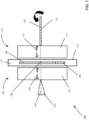
- FIG. 1 is a profile view of a schematic diagram of a magnetic mixing apparatus 100, in accordance with an embodiment.
- the magnetic mixing apparatus includes a driving magnet system 110 comprising one or more driving magnets, a driven magnet system 150 comprising one or more driven magnets, and a mixing chamber 171.
- the mixing chamber is disposed within a gap between the driving magnet system and the driven magnet system.
- the mixing chamber comprises a bounding surface 172 and contains a stir bar 190.
- the driving magnet system and driven magnet system will each contain the same number of magnets.
- the magnets will be arranged with the driving and driven magnet systems such that each magnet in the driven magnet system will be located directly, or nearly directly, across the gap from the corresponding magnet in the driving magnet system.
- the driving magnet system and/or the driven magnet system comprise a single, monolithic magnet.
- the driving magnet system comprises a single driving magnet 111 and the driven magnet system comprises a single driven magnet 151.
- the driving magnet system and/or the driven magnet system can comprise a plurality of magnets.
- the driving magnet system and the driven magnet system each comprise two magnets or more.
- the driving magnet comprises a driving magnet magnetic axis 113.
- the driven magnet also comprises a magnetic axis, referred to as the driven magnet magnetic axis 153.
- magnetic axis refers to a line through the center of a magnet such that torque exerted on the magnet by a magnetic field in the direction of the line is zero.
- a magnet will have its own magnetic axis.
- a magnetic system comprised of more than one magnet also will have its own composite magnetic axis, such that torque exerted on the magnetic system as a whole by a magnetic field in the direction of the line is zero. For visualization, FIG.
- FIG. 1 illustrates the magnetic axes 113 and 153 as separate, but parallel, from the rotations axes 120 and 160, respectively.
- the magnetic axis of the monolithic magnet will be substantially collinear with the rotational axis of that magnet.
- a shape of the driving magnet is the same as a shape of the driven magnet.
- dimensions of the driving magnet are the same as dimensions of the driven magnet.
- a shape of the driving magnet and a shape of the driven magnet can be a rectangular prism.
- a largest dimension of the driving magnet is in a plane perpendicular to the driving magnet magnetic axis and a largest dimension of the driven magnet is in a plane perpendicular to the driven magnet magnetic axis.
- a shortest dimension of the driving magnet is orthogonal to the largest dimension of the driving magnet and a shortest dimension of the driven magnet is orthogonal to the largest dimension of the driven magnet.
- the ratio of the largest dimension to the shortest dimension of the driving magnet and/or of the driven magnet is between 20 and 5.
- the driving magnet system and the driven magnet system are arranged to effectuate a magnetic coupling between the one or more driving magnets and the one or more driven magnets.
- each driving magnet and driven magnet are arranged with respect to one another such that an alignment of the driving magnet magnetic axis and an alignment of the driven magnet magnetic axis effectuate a magnetic coupling between the driving magnet and the driven magnet.
- the driven magnet magnetic axis is parallel to the driving magnet magnetic axis.
- the driven magnet magnetic axis is substantially collinear with the corresponding driving magnet magnetic axis.
- substantially collinear encompasses deviations from absolute collinearity of up to 10° and/or 3 mm at a plane bisecting the gap between the driving and driven magnet system.
- the magnetic coupling between the driving magnet system and the driven magnet system comprises an attractive magnetic coupling.
- the one or more driving magnets and the one or more driven magnets are arranged with respect to one another such that the alignment of the each driving magnet magnetic axis and the alignment of the each driven magnet magnetic axis effectuate an attractive magnetic coupling between the one or more driving magnets and the one or more driven magnets.
- the driving magnet magnetic axis and the driven magnet magnetic axis are aligned such that opposing poles of the driving magnet magnetic axis and the driven magnet magnetic axis are located in proximity to one another. For example, as shown in FIG.
- a first pole (e.g., a south pole) of the driving magnet magnetic axis is located in proximity to a second, opposing pole (e.g., a north pole) of the driven magnet magnetic axis.
- the second pole (e.g., the north pole) of the driving magnet magnetic axis is located in proximity to the first, opposing pole (e.g., the south pole) of the driven magnet magnetic axis.
- a strength of the magnetic coupling between the driving magnet system and driven magnet system is based on a distance of the gap located between the one or more driving magnets and the corresponding one or more driven magnets. Additionally, the magnetic coupling is based on a magnet strength of the one or more driving magnets, as well as a magnet strength of the one or more driven magnets.
- the gap separating a driving magnet and driven magnet is between about 10 mm and about 30 mm.
- the residual flux density of the driving magnet system is between 5000 and 40000 Gauss and the residual flux density of the driven magnet system is between 5000 and 40000 Gauss.
- the magnet strength of the one or more driving magnets is the same as the magnet strength of the one or more driven magnets.
- the mixing chamber is disposed within the gap between the driving magnet system and the driven magnet system.
- the mixing chamber is disposed within the gap such that the center, or midpoint, of the mixing chamber is located approximately an equal distance from the driving magnet system and from the driven magnet system.
- the mixing chamber has a mixing chamber volume. The bounding surface surrounds the mixing chamber volume.
- the stir bar can comprise any shape and/or volume.
- the shape of the stir bar can be selected from a group consisting of cylindrical, spherical, and triangular-prism-shaped.
- the stir bar frequently has a largest dimension 194 in a plane perpendicular to a stir bar rotational axis 192.
- the stir bar also has a shortest dimension orthogonal to the largest dimension. In a preferred embodiment, the ratio of the largest dimension to the shortest dimension of the stir bar is between 20 and 5.
- the stir bar can be an X-shaped stir bar that essentially is a composite of two rod-shaped bars, each having a largest dimension and a narrower shortest dimension orthogonal to the largest dimension.
- Such an X-shaped stir bar can be used with driving and driven magnet systems containing one, two or four magnets each.
- a shape of the stir bar can be selected from any other 3-dimensional shape not explicitly disclosed herein.
- the stir bar comprises a ferromagnetic material.
- the stir bar can comprise ferritic stainless steel or duplex stainless steel.
- a ferromagnetic material is a material that exhibits susceptibility to magnetization in the presences of a magnetic field. The magnetization may or may not persist after removal of the magnetic field.
- the stir bar has a relative magnetic permeability of between 500 - 1,000,000. In an embodiment in which a magnetic field travels through a ferromagnetic material, the magnetic domains of the material align within the magnetic field creating an area of low magnetic permeability, where the magnetic field can easily travel.
- the magnetic flux follows the path of least resistance through the ferromagnetic material, and may realign ferromagnetic material in order to minimize reluctance.
- the stainless steel can be passivated, which removes free iron from the surface of the bar, thus lowering the risk of oxidation.
- the stir bar can be encapsulated in an impermeable material corrosion resistance.
- impermeable material corrosion resistance One of ordinary skill in the art would be able to select an appropriate impermeable material that would not interfere with magnetic flux through the stir bar.
- Example materials include, but are not limited to PTFE, parylene C, parylene D, functionalized perfluoropolyethers (PFPEs), FEP, Xylan Fluoropolymer, epoxy, and urethane.
- the impermeable material can be applied to the stir bar by any method known in the art, such as by tumble coating.
- the ferromagnetic material of the stir bar is passivated prior to coating.
- the stir bar is tumble-coated with a layer of parylene C between 20 ⁇ m and 200 ⁇ m thick.
- a magnetic dipole By placing the ferromagnetic stir bar within the mixing chamber located in the gap between the driving magnet system and the driven magnet system, a magnetic dipole can be induced across the stir bar.
- This dipole of the stir bar effectuates a magnetic coupling between the stir bar, the one or more driving magnets, and the one or more driven magnets.
- the introduction of the stir bar into the magnetic field causes the stir bar to be attracted to the one or more driving magnets and the one or more driven magnets.
- a magnetic strength of the corresponding driving magnet equals a magnetic strength of the driven magnet
- the driving magnet magnetic axis is substantially collinear with the driven magnet magnetic axis
- attraction of the stir bar to the driving magnet and driven magnet causes the stir bar to be located roughly equidistant from driving magnet and driven magnet.
- a center of the mixing chamber is located an equal distance from the driving magnet system and the driven magnet system, as a result of the attractive forces between the stir bar and the one or more driving magnets and the stir bar and the one or more driven magnets, the stir bar can be centered within the mixing chamber thereby minimizing the amount of contact between the stir bar and the bounding surface.
- the stir bar aligns within the magnetic fields generated by the driving magnet system and the driven magnet system such that areas of the magnetic fields with the greatest magnetic field strengths travel through the greatest volume of the stir bar possible.
- the overall magnetic field produced as a result of this overlap comprises a magnetic field with parallel magnetic field lines.
- the magnetic field produced consists of parallel magnetic field lines traveling from the driving magnet to the driven magnet, and from the driven magnet to the driving magnet.
- the stir bar aligns within the mixing chamber such that the stir bar is maximally permeated by these parallel magnetic field lines.
- the stir bar aligns within the mixing chamber such that the driving magnet magnetic axis and the driven magnet magnetic axis are parallel to and pass through the largest dimension of the stir bar permitted by the boundaries of the mixing chamber.
- the magnetic field is strongest along the largest dimension of the driving magnet system and the driven magnet system.
- the magnetic field strength drops rapidly when moving outward in a direction parallel to the shortest dimension of the magnet system.
- the ferromagnetic stir bar is pulled toward the position which allows the highest magnetic flux to pass through its highly-permeable volume.
- the torque which causes the stir bar to turn in response to the turning of the driving and driven magnet systems is approximately proportional to the gradient to the magnetic field traveling through the stir bar.
- the driving magnet system is configured to rotate about a driving magnet rotational axis 120. As shown in FIG. 1 , the driving magnet rotational axis typically is parallel to the driving magnet magnetic axis. In further, preferred embodiments, the driving magnet rotational axis can be substantially collinear with the driving magnet magnetic axis. In a preferred embodiment, the driving magnet system is symmetric with respect to the driving magnet rotational axis.
- rotation of the driving magnet system can be achieved by operably coupling the driving magnet system to a driving magnet spindle 121 and operably coupling the driving magnet spindle to a drive motor (shown in FIG. 3A ).
- the driving magnet rotational axis preferably is parallel to the driving magnet spindle. More preferably, the driving magnet rotational axis is substantially collinear with the driving magnet spindle.
- the one or more driving magnets are mounted in a driving magnet holder (shown in FIG. 3A ) and the driving magnet holder is configured to rotate about the driving magnet rotational axis.
- this rotation of the driving magnet holder can be achieved by operably coupling the driving magnet holder to the driving magnet spindle and operably coupling the driving magnet spindle to the drive motor.
- the magnetic mixing apparatus may not include the driving magnet spindle.
- rotation of the driving magnet system can be generated from a peripheral drive.
- the driven magnet system is configured to rotate about a driven magnet rotational axis 160.
- the driven magnet system comprises a single driven magnet having a driven magnet rotational axis parallel to the driven magnet magnetic axis.
- the driven magnet rotational axis is substantially collinear with the driven magnet magnetic axis.
- the driven magnet system is symmetric with respect to the driven magnet rotational axis.
- the driven magnet system can be operably coupled to a driven magnet spindle 161.
- the driven magnet rotational axis is parallel to the driven magnet spindle.
- the driven magnet rotational axis can be substantially collinear with the driven magnet spindle.
- the one or more driven magnets are mounted in a driven magnet holder (shown in FIG. 3A ) and the driven magnet holder is configured to rotate about the driven magnet rotational axis.
- the driving magnet holder can be operably coupled to the driven magnet spindle.
- the driven magnet rotational axis is parallel to the driving magnet rotational axis.
- the driven magnet rotational axis can also be substantially collinear with the driving magnet rotational axis. Collinearity of the driven magnet rotational axis and the driving magnet rotational axis is a preferred embodiment because it enhances the strength of the attractive magnetic coupling between the driving magnet system and the driven magnet system, by maximizing alignment of the driving magnet(s) and driven magnet(s) as they rotate about their respective axes.
- the one or more driven magnets rotate about the driven magnet rotational axis such that opposing poles of the magnetic axis of each of the one or more driving magnets and the magnetic axis of the corresponding one or more driven magnets are located in proximity to one another.
- the driven magnet rotates about the driven magnet rotational axis such that the driven magnet magnetic axis is as close to collinear with the corresponding driving magnet magnetic axis as possible.
- the stir bar is also capable of rotating about the stir bar rotational axis.
- rotation of the one or more driving magnets about the driving magnet rotational axis and rotation of the one or more driven magnets about the driven magnet rotational axis induces rotation of the stir bar about the stir bar rotational axis.
- the rotational axis about which the stir bar rotates is aligned with respect to the stir bar based on the alignment of a driving magnet magnetic axis and driven magnet magnetic axis.
- the stir bar is aligned within the mixing chamber such that the greatest magnetic flux possible travels through the stir bar.
- the largest dimension of the stir bar permissible by the bounding surfaces is parallel to the driving magnet magnetic axis and the to the driven magnet magnetic axis.
- the stir bar rotates about the stir bar rotational axis such that the largest volume of the stir bar remains within the strongest portions of the magnetic field formed between the one or more driving magnets and the one or more driven magnets as possible.
- the stir bar rotational axis is substantially collinear with the magnetic axis of the driving magnetic system and the magnetic axis of the driving magnetic system.
- the driving magnet magnetic axis, the driven magnet magnetic axis, the driving magnet rotational axis, the driven magnet rotational axis, and the stir bar rotational axis are all substantially collinear with one another.
- This is a preferred embodiment because it enables the stir bar to be substantially centered or "balanced" within the mixing chamber such that the stir bar minimally contacts the bounding surface of the mixing chamber.
- the stir bar is positioned within the mixing chamber such that a plane of rotation of the stir bar is equidistant from the driving magnet system and the driven magnet system. The plane of rotation of the stir bar is perpendicular to the stir bar rotational axis.
- the plane of rotation of the stir bar is parallel to the largest dimension of the stir bar.
- the stir bar minimally contacts the bounding surface of the mixing chamber. Decreasing the amount of contact between the stir bar and the bounding surface of the mixing chamber is discussed in greater detail below.
- an acoustic mechanism for detecting magnetic decoupling of the stir bar from the driving magnet system and/or the driven magnet system during mixing can be optionally included in the magnetic mixing apparatus.
- an amplitude of vibrations produced by the rotating stir bar increases. If the stir bar decouples from the driving magnet system and the driven magnet system, the amplitude of the vibrations produced by the rotating stir bar suddenly decreases, often immediately following several loud knocks.
- the mechanism used to detect decoupling of the stir bar can be a microphone (not shown).
- the microphone is directional, and focused on the mixing assembly.
- the microphone can be non-directional and simply placed in proximity to the mixing assembly.
- the audio output from the stir bar can be bandpass filtered, such that only certain relevant frequencies are measured. Additionally, in some embodiments, the exact frequency and amplitude associated with a decoupling event can be experimentally determined for a given magnetic mixing assembly, and used by the microphone to detect decoupling of the stir bar.
- the mechanism used to detect decoupling of the stir bar can be an accelerometer (not shown) that is attached to the mixing assembly.
- the accelerometer can be used to detect the sudden decrease in amplitude that occurs when the stir bar decouples.
- FIG. 2 is a profile view of a schematic diagram of a magnetic mixing apparatus 200, in accordance with an embodiment.
- the magnetic mixing apparatus includes a driving magnet system 210 and a driven magnet system 250.
- the driving magnet system comprises a first driving magnet 211 and a second driving magnet 216 separated by a distance that transects the driving magnet rotational axis 220
- the driven magnet system comprises a first driven magnet 251 and a second driven magnet 256 separated by a distance that transects the driven magnet rotational axis 260.
- the first driving magnet, the second driving magnet, the first driven magnet, and the second driven magnet each have a magnetic axis.
- the first driving magnet has a first driving magnet magnetic axis 213
- the second driving magnet has a second driving magnet magnetic axis 218,
- the first driven magnet has a first driven magnet magnetic axis 253, and the second driven magnet has a second driven magnet magnetic axis 258.
- the first driving magnet magnetic axis and the second driving magnet magnetic axis are parallel to one another
- the first driven magnet magnetic axis and the second driven magnet magnetic axis are parallel to one another.
- first driving magnet magnetic axis, the second driving magnet magnetic axis, the first driven magnet magnetic axis, and the second driven magnet magnetic axis are parallel to one another.
- first driving magnet magnetic axis and the first driven magnet magnetic axis are substantially collinear with one another and the second driving magnet magnetic axis and the second driven magnet magnetic axis are substantially collinear with one another.
- the poles of the first driving magnet are arranged with respect to the first driving magnet magnetic axis in the same arrangement as the poles of the second driving magnet with respect to the second driving magnet magnetic axis.
- the poles of the first driven magnet are arranged with respect to the first driven magnet magnetic axis in the same arrangement as the poles of the second driven magnet with respect to the second driven magnet magnetic axis.
- a magnet strength of the first driving magnet equals a magnet strength of the second driving magnet
- a magnet strength of the first driven magnet equals a magnet strength of the second driven magnet.
- magnet strengths of the first driving magnet, the second driving magnet, the first driven magnet, and the second driven magnet are all the same.
- the first driving magnet and the second driving magnet can comprise any shape and/or size.
- the first driven magnet and the second driven magnet can comprise any shape and/or size.
- a shape of the first driving magnet is the same as a shape of the second driving magnet
- a shape of the first driven magnet is the same as a shape of the second driven magnet.
- a shape of the first driving magnet, a shape of the second driving magnet, a shape of the first driven magnet, and a shape of the second driven magnet are all the same.
- the first driving magnet, the second driving magnet, the first driven magnet, and the second driven magnet each comprise a cube.
- dimensions of the first driving magnet are the same as dimensions of the second driving magnet, and dimensions of the first driven magnet are the same as dimensions of the second driven magnet. In a further preferred embodiment, dimensions of the first driving magnet, the second driving magnet, the first driven magnet, and the second driven magnet are all the same.
- the first driving magnet is located approximately an equal distance from the driving magnet rotational axis as the second driving magnet.
- the first driven magnet is located approximately an equal distance from the driven magnet rotational axis as the second driven magnet.
- the first driving magnet, the second driving magnet, the first driven magnet, and the second driven magnet are all located an equivalent distance from their respective rotational axes. This is a preferred embodiment because it enables the magnets to generate symmetric magnetic fields with respect to their rotational axes.
- the first driving magnet is located approximately an equal distance from a mixing chamber 271 as the second driving magnet.
- the first driven magnet is located approximately an equal distance from the mixing chamber as the second driven magnet.
- the first driving magnet, the second driving magnet, the first driven magnet, and the second driven magnet are all located an equivalent distance from the mixing chamber. This is a preferred embodiment because it enables the magnets to generate symmetric magnetic fields with respect to the mixing chamber.
- the largest dimension of the driving magnet system is the distance from the outside edge of the first driving magnet to the outside edge of the second driving magnet, including the any intervening spacer
- a largest dimension of the driven magnet system comprises the distance from the outside edge of the first driven magnet to the outside edges of the second driven magnet, including any intervening spacer.
- the largest dimension of the driving magnet system typically is in a plane perpendicular to the rotational axis of the driving magnetic system.
- the largest dimension of the driven magnet system typically is in a plane perpendicular to the rotational axis of the driven magnet system.
- a shortest dimension of the driving magnet system is orthogonal to the largest dimension of the driving magnet system and a shortest dimension of the driven magnet system is orthogonal to the largest dimension of the driven magnet system.
- the driving magnet system comprises a spacer that bridges the distance between the first driving magnet and the second driving magnet, and connects the first driving magnet and the second driving magnet.
- the spacer transects the driving magnet rotational axis.
- the driven magnet system comprises a spacer that bridges the distance between the first driven magnet and the second driven magnet, and connects the first driven magnet and the second driven magnet.
- the spacer transects the driven magnet rotational axis.
- the geometry of the spacer can be adapted to be capable of bridging more than two points and intercept the driving magnet spindle or driven magnet spindle.
- the spacer that connects the first driving magnet and the second driving magnet and/or the first driven magnet and the second driven magnet can take any form.
- the first driving magnet and the second driving magnet can be mounted and held in a driving magnet holder 425
- the first driven magnet and the second driven magnet can be mounted and held in a driven magnet holder 465.
- a driving magnet spindle 221 is positioned between the first driving magnet and the second driving magnet and/or a driven magnet spindle 261 is positioned between the first driven magnet and the second driven magnet.
- a spacer connects the first driving magnet to the second driving magnet and the first driven magnet to the second driven magnet (as illustrated in FIG. 2 )
- the driving magnet spindle and the driven magnet spindle can be connected to the respective spacer.
- FIG. 3A is an illustration of one embodiment of a magnetic mixing apparatus 300, in accordance with the present disclosure.
- the magnetic mixing apparatus includes a driving magnet holder 325, a driven magnet holder 365, and a gap located between the driving magnet holder and the driven magnet holder.
- the driving magnet system in some embodiments the single, first driving magnet of FIG. 1 and in alternative embodiments more than one driving magnet, e.g., the first driving magnet and the second driving magnet of FIG. 2
- the driven magnet system in some embodiments the single, first driven magnet of FIG. 1 and in alternative embodiments more than one driven magnet, e.g., the first driven magnet and the second driven magnet of FIG.
- the driving magnet holder holds the driving magnet system in a stationary position and the driven magnet holder holds the driven magnet system in a stationary position in accordance with the embodiments discussed with regard to FIGS. 1 and 2 .
- the driving magnet holder comprises the same specifications (e.g., shape, size, material composition, and/or weight) as the driven magnet holder.
- the driving magnet holder and the driven magnet holder are aligned with one another across the gap which is configured to accommodate a mixing chamber.
- the driving magnet system is configured to rotate around the driving magnet rotational axis.
- the driving magnet holder can be configured to rotate around the driving magnet rotational axis.
- the driving magnet holder can be operably coupled to a drive motor 330 that is capable of driving rotation of the driving magnet holder about the driving magnet rotational axis.
- the driving magnet holder can be mechanically coupled to the drive motor.
- the drive motor can be in line with and directly drive rotation of the driving magnet holder. Alternatively, the drive motor can be indirectly, but operably, coupled to the driving magnet spindle.
- the driving magnet spindle can be operably and/or mechanically coupled to a drive belt 332, which in turn can be operably and/or mechanically coupled to the drive motor that is capable of driving rotation of the driving magnet holder about the driving magnet rotational axis.
- the drive belt is capable of rotating the driving magnet spindle such that the driving magnet holder that is operably coupled to the driving magnet spindle, rotates.
- the driving magnet system is not mounted within the driving magnet holder. Instead, the driving magnet system itself can be operably and/or mechanically coupled to the drive motor. This operative and/or mechanical coupling between the driving magnet system and the drive motor can be via the drive belt and/or the driving magnet spindle as described above.
- the driven magnet system is configured to rotate around the driven magnet rotational axis.
- the driven magnet holder can be configured to rotate around the driven magnet rotational axis.
- the driven magnet holder can be operably coupled to the driven magnet spindle.
- the driven magnet spindle can be substantially collinear with the driven magnet rotational axis.
- a mixing assembly holder 340 is disposed within the gap between the driving magnet holder and the driven magnet holder.
- a mixing assembly that is configured to be held in a stationary position within the mixing assembly holder is discussed in further detail with regard to FIG. 3B .
- there is no mixing assembly holder and the mixing assembly is itself disposed directly in the gap between the driving magnet holder and the driven magnet holder.
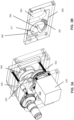
- FIG. 3B is an illustration of a mixing assembly 370, in accordance with an embodiment of the disclosed subject matter.
- the mixing assembly comprises a mixing chamber 371, a stir bar 390, a sample loading well 383, a sample transfer channel 386, an air channel 382, and bead filter channels 387.
- the mixing assembly can comprise additional fluid channels and/or air channels.
- the mixing assembly is configured to be disposable.
- the mixing assembly is configured to be sanitizable, e.g., with bleach and/or alternative cleaning material, to permit multiple uses.
- the sample loading well is configured to receive a fluid sample from a sample inlet (illustrated in FIG. 8A ) and contain the fluid sample prior to transfer of the fluid sample to the mixing chamber.
- the mixing chamber holds a first liquid, such as a lysis buffer, while the sample chamber contains the fluid sample.
- the fluid sample comprises one or more cells.
- the sample transfer channel is configured to transport the fluid sample from the sample loading well into the mixing chamber.
- An air outlet is configured to transfer air between an air port and the air channel. The air channel transfers air between the air outlet and the mixing chamber.
- the pressure of the air within the air channel controls the operation of the mixing assembly, and specifically controls the entry and exit of fluids to and from the mixing chamber.
- the mixing chamber further comprises beads (shown in FIGS. 8A-D ).
- the fluid sample transferred to the mixing chamber comprises one or more cells
- mixing the fluid sample with the beads promotes lysis of the one or more cells.
- the fluid sample is removed from the mixing chamber.
- the beads are separated from the fluid sample in conjunction with the sample being removed from the mixing chamber.
- bead filter channels are appended to the mixing chamber. The bead filter channels are located along an edge of the mixing chamber and are configured to retain the beads in the mixing chamber while allowing the fluid sample to exit.
- a cross sectional area of each bead filter channel comprises a first dimension such that the beads are too large to enter the bead filter channels, and a second dimension such that the beads are unable to block fluid flow.
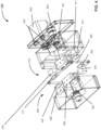
- FIG. 4 is an illustration of an exploded view of a magnetic mixing apparatus 400, in accordance with an embodiment.
- a driving magnet system 410 comprises a first driving magnet 411 and a second driving magnet 416 separated by a distance
- a driven magnet system 450 comprises a first driven magnet 451 and a second driven magnet 456 separated by a distance as shown in FIG. 2 .
- the overall magnetic field produced as a result of this overlap comprises a magnetic field with parallel magnetic field lines.
- the magnetic field produced consists of parallel magnetic field lines traveling from the driving magnet system to the driven magnet system, and from the driven magnet system to the driving magnet system.
- certain embodiments of the magnetic mixing apparatus can comprise one or more field focusers.
- the field focusers are coupled to at least one of the one or more driving magnets or the one or more driven magnets, and are positioned to focus magnetic fields generated by the driving magnet system and the driven magnet system towards a narrow radial segment along a largest dimension of the driving and driven magnetic systems.
- Field focusers can be coupled to the one or more magnets of the driving magnet system and/or the driven magnet system, and steepen the magnetic field gradient across the gap. The field focusers concentrate the magnetic fields generated by the driving magnet system and the driven magnet system into a smaller cross-sectional area, thereby increasing the magnetic flux passing through the stir bar.
- the field focusers By steepening the magnetic field gradients, the field focusers increase the potential torque on the stir bar during rotation of the stir bar.
- Magnetic field lines of the driving magnet system and the driven magnet system that have been transformed by field focusers are depicted in FIG. 5 .
- the approximately equivalent magnet strength would be distributed over the larger area of the face of the magnet (e.g. 511).
- the driving magnet system and the driven magnet system can each be coupled to a field focuser.
- the first driving magnet, the second driving magnet, the first driven magnet, and the second driven magnet are each coupled to a field focuser.
- the first driving magnet is coupled to a first driving magnet field focuser 412
- the second driving magnet is coupled to a second driving magnet field focuser 417
- the first driven magnet is coupled to a first driven magnet field focuser 452
- the second driven magnet is coupled to a second driven magnet field focuser 457.
- a single field focuser can be coupled to each of the single driving magnet and the single driven magnet.
- the field focusers are comprised of iron. Iron is permeable to magnetic fields, meaning that magnetic fields generated by the driving magnet system and/or the driven magnet system can pass through iron field focusers that are coupled to the driving magnet system and/or the driven magnet system.
- the field focusers are triangular-prism shaped. In embodiments in which the field focusers are coupled to the driving magnet system and the driven magnet system, the field focusers are positioned to focus magnetic fields that are generated by the driving magnet system and the driven magnet system towards the center of the mixing chamber. These magnetic field gradients constrain the stir bar to the center of the mixing chamber.
- the use of field focusers in the magnetic mixing apparatus is optional. In alternative embodiments, the magnetic mixing apparatus does not comprise field focusers.
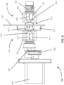
- FIG. 5 is an illustration of a profile view of a magnetic mixing apparatus 500, in accordance with an embodiment.
- FIG. 5 includes a drive motor 530, a drive belt 532, a driving magnet spindle 521, a driving magnet holder 525, a mixing assembly 570, a driven magnet holder 565, and a driven magnet spindle 561 arranged to mix a sample contained within a mixing chamber 571 of the mixing assembly.
- the drive motor is operably/mechanically coupled to the drive belt, which is operably/mechanically coupled to the driving magnet spindle, which is in turn operably coupled to the driving magnet holder.
- the driving magnet holder contains a driving magnet system 510 (in some embodiments, a first driving magnet 511 and a second driving magnet (not shown)). As discussed above, the driving magnet holder is positioned in proximity to a first face of the mixing assembly such that the driving magnet holder is aligned with the mixing chamber. The driven magnet holder is positioned in proximity to a second face of the mixing assembly that is opposite the first face, such that the driven magnet holder is also aligned within the mixing chamber, and such that the mixing chamber is located between the driving magnet holder and the driven magnet holder.
- the driven magnet holder contains a driven magnet system 550 (in some embodiments, the first driven magnet 551 and the second driven magnet (not shown)). Finally, the driven magnet holder is operably coupled to the driven magnet spindle.
- a first driving magnet field focuser 512 can be coupled to the first driving magnet and/or a first driven magnet field focuser 552 can be coupled to the first driven magnet.
- the first driving magnet field focuser and the first driven magnet field focuser transform the magnetic field lines produced by the first driving magnet and the first driven magnet to produce magnetic field lines 575 shown in FIG. 5 .
- the magnetic field lines comprise a gradient pattern, with a lowest magnetic field strength near the exterior edges of the magnet, and a greatest magnetic field strength near a center 573 of the magnet.
- the driving magnet holder and the driven magnet holder are located approximately an equal distance from the center of the mixing chamber.
- the driving magnet holder and the driven magnet holder can each be located a distance of 7 mm from the center of the mixing chamber.
- the driving magnet system and the driven magnet system can be located an equal distance from the center of the mixing chamber.
- the driving magnet system and the driven magnet system can each be located a distance of 7 mm from the center of the mixing chamber.
- the first driving magnet field focuser and the first driven magnet field focuser can be located an equal distance from the center of the mixing chamber.
- the first driving magnet field focuser and the first driven magnet field focuser can each be located a distance of 7 mm from the center of the mixing chamber.
- FIG. 6 is an illustration of a cross section of a profile view of a mixing assembly 670, in accordance with an embodiment. Specifically, FIG. 6 depicts a stir bar 690 located within a mixing chamber 671. Note that bounding surfaces 672A and 672B of the mixing chamber need not be of uniform thickness on all faces of the mixing chamber. In some implementations, it is desirable to heat or cool the contents of the mixing chamber. Therefore, in certain embodiments, one wall of the mixing chamber (for example a bounding surface 672B) is relatively thin and thermally conductive.
- a supportive plate (not shown) can be positioned adjacent to the thin bounding surface to support the spinning stir bar and/or the pressurized filling of the mixing chamber (discussed with regard to FIGS. 8A-D ).
- An embodiment of the supportive plate is depicted in FIG. 7 and discussed in greater detail below.
- the stir bar minimally contacts the bounding surface of the mixing chamber.
- the dimensions of the mixing chamber and stir bar are proportioned such that the stir bar seldom contacts the bounding surface of the mixing chamber.
- a largest dimension of the mixing chamber will be less than largest dimension 694 of the stir bar.
- the largest dimension of the mixing chamber can be 1 mm - 10 mm greater than a largest dimension of the stir bar.
- the largest dimension of the mixing chamber volume can comprise between 1 mm - 200 mm.
- the largest dimension of the mixing chamber volume is selected from the group comprising about 2-100 mm, about 10-80 mm, and about 20-30 mm.
- the largest dimension of the stir bar is between 0.5 mm - 180 mm.
- the largest dimension of the stir bar is selected from the group comprising about 1-100 mm, about 3-50 mm, and about 5-30 mm.
- the stir bar does not contact the bounding surface of the mixing chamber. In alternative embodiments, the stir bar can contact the bounding surface of the mixing chamber, but more infrequently than would if the driving magnet system were present, but the driven magnet system were absent.
- the mixing chamber volume can comprise between 0.1 mL - 100 mL. In a preferred embodiment, the mixing chamber volume is selected from the group comprising about 1-20 mL, about 2-10 mL, and about 3-6 mL. In a further embodiment, the stir bar volume can comprise between 50 uL - 10 mL. In a preferred embodiment, the stir bar volume is selected from the group comprising less than 1 mL, about 0.1-0.8 mL, and about 0.3-0.5 mL.
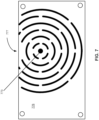
- FIG. 7 illustrates a supportive plate 776, in accordance with an embodiment.
- the supportive plate may be located adjacent to one or more thin bounding surfaces of a mixing chamber to support spinning of a stir bar within the mixing chamber and/or pressurization of the mixing chamber.
- the supportive plate is located within the gap between the driving magnet system and driven magnet system.
- the supportive plate can comprise a thermoconductive material, which can be heated and/or cooled in order to heat and/or cool the contents of the mixing chamber.
- the supportive plate can comprise aluminum.
- rotating magnets may induce eddy currents in the supportive plate.
- a conductive plane such as the supportive plate (for example, a driving magnet rotational axis and/or a driven magnet rotational axis)
- eddy currents can be generated in the conductive plane. These eddy currents have the potential to interact with and create a drag force on the one or more rotating magnets.
- This drag force can result in a loss of transferred torque between the one or more rotating magnets.
- drag force on the driving magnet system and/or the driven magnet system can result in a loss of transferred torque from the driving magnet system to the driven magnet system and/or to the stir bar.
- This loss in transferred torque can cause the one or more rotating magnets to decouple, particularly at high speeds of angular rotation.
- a loss of transferred torque can cause the driven magnet system to decouple from the driving magnet system.
- the supportive plate can optionally include a plurality of perforations 777.
- the driving magnet system and the driven magnet system rotate in a circular pattern.
- eddy currents that are induced in the supportive plate by the rotating magnet systems are induced radially from a center 773 of the circular pattern.
- the plurality of perforations can be arranged in a concentric pattern around the center of the circular pattern of rotation of the magnet systems.
- the plurality of perforations can be arranged concentrically with the mixing chamber and/or with the stir bar contained within the mixing chamber.
- This concentric arrangement of the plurality of perforations causes the eddy currents induced in the supportive plate to follow a convoluted path along their radial induction pathways. This convoluted pathway limits the formation of the eddy currents in the supportive plate.
- drag on the rotating magnet systems that is caused by the eddy currents is limited to below a threshold that will interfere with effective coupling of the driving magnet system, driven magnet system and stir bar.
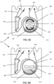
- FIGS. 8A-D illustrate one exemplar mixing method implemented on a mixing assembly 870, according to an embodiment of the invention.
- the mixing assembly comprises a mixing chamber 871 surrounded by a bounding surface 872.
- the mixing chamber contains a stir bar 890 and optionally a plurality of beads 874.
- the mixing assembly illustrated in FIGS. 8A-D also includes a sample loading well 883 and a sample transfer channel 886.
- the sample transfer channel connects the sample loading well and the mixing chamber.
- a chamber loading channel 885 permits introduction of reagents, including e.g. a lysis solution or beads into the mixing chamber without interacting with sample in the sample chamber. Pneumatic control of fluid movement is provided by air pressure supplied via an air channel 882.
- FIG. 8A illustrates a first step of a mixing process performed using the mixing assembly, in accordance with an embodiment.
- a sample is loaded into a sample inlet 881 and a lysis buffer is loaded into the chamber loading channel.
- the sample comprises one or more cells.
- the lysis buffer comprises one or more chemical lysing agents including, but not limited to, hypotonic solutions, and/or solutions containing an organic solvent (such as an alcohol, ether or chloroform), a chelating agent (such as ethylenediaminetetraacetic acid (EDTA)), a surfactant (such as Triton or sodium dodecyl sulfate (SDS)), and/or a chaotropic agent (such as urea or guanidine).
- an organic solvent such as an alcohol, ether or chloroform
- a chelating agent such as ethylenediaminetetraacetic acid (EDTA)
- EDTA ethylenediaminetetraacetic acid
- SDS sodium dodecyl sulfate
- a chaotropic agent such as urea or guanidine
- FIG. 8B illustrates a second step of the mixing process performed using the mixing assembly, in accordance with an embodiment.
- the sample is located within the sample loading well.
- the air channel is open, and air is forced through the air channel and into the sample loading well.
- the air has an air pressure of 20 psi.
- the sample inlet is closed so that fluid (including the air from the air channel and/or the sample located in the sample loading well) cannot escape the sample loading well through the sample inlet.
- a pressure inside the sample loading well is increased. This increased pressure within the sample loading well causes the sample to be pushed out of the sample loading well, into the sample transfer channel, and finally into the mixing chamber.
- the chamber loading channel and the sample exit channel are closed such that fluid (such as the lysis buffer and the sample located within the mixing chamber) cannot escape from the mixing chamber.
- FIG. 8C illustrates a third step of the mixing process performed using the mixing assembly, in accordance with an embodiment.
- the sample and the lysis buffer are located within the mixing chamber.
- the air pressure in the sample loading well is maintained at a constant pressure.
- the sample inlet, the chamber loading channel, and the sample exit channel remain closed such that such that fluid (such as the lysis buffer and the sample located within the mixing chamber) cannot escape from the mixing chamber.
- the sample and the lysis buffer remain enclosed within the mixing chamber.
- the stir bar rotates responsive to coupled rotations of the driving and driven magnet systems.
- rotation of the stir bar is caused by energizing a drive motor that is operably coupled to a driving magnet system, thereby inducing rotation of the driving magnet system.
- the driving magnet system is magnetically coupled to a driven magnet system, and thus rotation of the driving magnet system induces rotation of the driven magnet system.
- the driving magnet system and the driven magnet system are both operably coupled to the stir bar.
- rotation of the driving magnet system and rotation of the driven magnet system induces rotation of the stir bar seen in FIG. 8C .
- This rotation of the stir bar mixes the sample and the lysis buffer located within the mixing chamber.
- the sample comprises one or more cells
- mixing of the sample and the lysis buffer promotes lysis of the one or more cells.
- the plurality of beads located within the mixing chamber further promote lysis of the one or more cells.
- FIG. 8D illustrates a fourth step of the mixing process performed using the mixing assembly, in accordance with an embodiment.
- rotation of the stir bar has stopped, and the sample and the lysis buffer are located within the mixing chamber.
- the sample comprises a lysed sample as a result of the mixing shown in FIG. 8C .
- the air channel is open, and pneumatic pressure is applied to the air channel and into the sample loading well.
- the sample inlet and the chamber loading channel remain closed such that such that fluid (e.g., the mixed lysis buffer and the sample) cannot escape from the mixing chamber via the sample inlet and/or the chamber loading channel.
- the sample exit channel is now open.
- the lysed sample can travel out of the mixing chamber, through the sample exit channel, and into the environment of the mixing assembly where the lysed sample can be collected.
- the beads are separated from the fluid sample in conjunction with the sample being removed from the mixing chamber.
- bead filter channels 887 located along an edge of the mixing chamber retain the beads in the mixing chamber while allowing the fluid sample to exit the mixing chamber.
- a cross sectional area of each bead filter channel comprises a first dimension such that the beads are too large to enter the bead filter channels, and a second dimension such that the beads are unable to block fluid flow.
- Phosphate buffered saline PBS was spiked with titered Candida albicans at a concentration of 1000 CFU/ml and supplemented with bovine serum albumin (BSA) to a final concentration of 0.9 mg/ml.
- BSA bovine serum albumin
- a prefilled tube containing 0.7 mL dry volume of 0.1 & 0.5 mm zirconia beads Zymo Research BashingBead TM , catalog no. S6012-50 was added to the mixing chamber (including stir bar).
- 1 ml of lysis buffer Zymo Research, Irvine, CA
- 500 ⁇ l of sample then was added to the mixing chamber and stir bar rotated using the mixing apparatus as described herein at 3000 rpm for 1 minute.
- the lysate was collected, bound to a Zymo Research Zymo-Spin IIC-XL column, washed and eluted using standard spin column centrifugation steps.
- Bench controls using lysis buffer alone, or lysis buffer plus beads, were performed as follows: 500 ⁇ l of sample was mixed with 1 mL of lysis buffer. The resulting mixture was then added, or not, to a prefilled tube containing 0.7 mL dry volume of 0.1 & 0.5 mm zirconia beads, attached horizontally to a vortex, and vortexed for 1 minute.
- the lysate was collected, bound to a Zymo Research Zymo-Spin IIC-XL column, washed and eluted using standard spin column centrifugation procedure.
- Lysis was evaluated via RT-qPCR.
- a 20 ⁇ l reaction contained 10 ⁇ l of 2X reaction buffer and 0.8 ⁇ l enzyme mix, Clontech One Step SYBRPrimescript RT-PCR Kit II, 250nm forward and reverse primers to C . albicans 28S ribosomal RNA, 4 ⁇ l extracted nucleic acid.
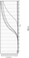
- the reactions were processed on a Roche LC96 lightcycler with the following protocol: 10 min at 42°C for reverse transcription, enzyme inactivation at 95° for 10 sec, followed by 45 cycles of denaturation at 95°C for 20 sec, annealing at 60°C for 20 sec, extension at 72° for 15 sec. Amplification curves are illustrated in FIG. 9 .
- Bench extractions with and without bead beating were used as controls and the extractions evaluated via RT-qPCR.
- the experiment was replication (data not shown) and both iterations showed less than 1 cycle difference in Cq values relative to bench experiments.
- the amplification curves depicted in FIG. 9 indicate that approximately the same quantity of the DNA sequence was initially detected when the reaction solution was mixed using the mixing assembly, compared to when the reaction solution was mixed using the vortex mixer and zirconia beads.
Landscapes
- Life Sciences & Earth Sciences (AREA)
- Chemical & Material Sciences (AREA)
- Health & Medical Sciences (AREA)
- Engineering & Computer Science (AREA)
- Organic Chemistry (AREA)
- Zoology (AREA)
- Wood Science & Technology (AREA)
- Bioinformatics & Cheminformatics (AREA)
- Biotechnology (AREA)
- Genetics & Genomics (AREA)
- Microbiology (AREA)
- General Health & Medical Sciences (AREA)
- Biomedical Technology (AREA)
- Biochemistry (AREA)
- General Engineering & Computer Science (AREA)
- Sustainable Development (AREA)
- Chemical Kinetics & Catalysis (AREA)
- Molecular Biology (AREA)
- Cell Biology (AREA)
- Mycology (AREA)
- Medicinal Chemistry (AREA)
- Tropical Medicine & Parasitology (AREA)
- Virology (AREA)
- Mixers With Rotating Receptacles And Mixers With Vibration Mechanisms (AREA)
- Dynamo-Electric Clutches, Dynamo-Electric Brakes (AREA)
Claims (15)
- Appareil de mélange magnétique (100) comprenant :un système d'aimant entraînant (110) configuré pour tourner autour d'un axe de rotation d'aimant entraînant (120), le système d'aimant entraînant (110) comprenant un ou plusieurs aimants entraînants (111) ;un moteur d'entraînement (530), dans lequel le système d'aimant entraînant (110) est couplé de manière fonctionnelle au moteur d'entraînement (530), et le moteur d'entraînement (530) est capable d'entraîner la rotation du système d'aimant entraînant (110) autour de l'axe de rotation d'aimant entraînant (120) ;un système d'aimant entraîné (150) configuré pour tourner autour d'un axe de rotation d'aimant entraîné (160), le système d'aimant entraîné (150) comprenant un ou plusieurs aimants entraînés (151) ;un écartement séparant le système d'aimant entraînant (110) et le système d'aimant entraîné (150),
dans lequel l'agencement des systèmes d'aimant entraîné (150) et entraînant (110) effectue un couplage magnétique entre chaque aimant entraînant (111) et un aimant entraîné correspondant (151) par quoi la rotation du système d'aimant entraînant (110) autour de l'axe de rotation d'aimant entraînant (120) provoque la rotation du système d'aimant entraîné (150) autour du l'axe de rotation d'aimant entraîné (160);un ensemble de mélange stationnaire (870) disposé au sein de l'écartement, dans lequel l'ensemble de mélange (870) comprend une chambre de mélange (171, 871) ayant un volume de chambre de mélange et comprenant une surface de liaison (172, 872) entourant le volume de chambre de mélange avec un canal de transfert d'échantillon (886) et un canal de sortie d'échantillon (888) en communication fluidique avec le volume de chambre de mélange au sein de la chambre de mélange (171, 871), la chambre de mélange (171, 871) incluant en outre :un canal de charge de chambre (885) destiné à l'introduction de réactifs ;un canal d'air (882) destiné à la commande pneumatique du mouvement de fluide par la pression de l'air ;et des canaux de filtre à billes (887) situés le long d'un bord de la chambre de mélange (171, 871) pour retenir les billes dans la chambre de mélange (171, 871) tout en permettant que l'échantillon de fluide sorte de la chambre de mélange (171, 871) ; etune barre d'agitation (190, 890) contenue au sein du volume de chambre de mélange, la barre d'agitation (190, 890) comprenant un volume de barre d'agitation et un matériau ferromagnétique, dans lequel la disposition de la barre d'agitation (190, 890) entre le système d'aimant entraînant (110) et le système d'aimant entraîné (150) crée un circuit magnétique à faible réluctance et effectue un couplage magnétique entre la barre d'agitation (190, 890), au moins l'un des un ou plusieurs aimants entraînant (111), et au moins l'un des un ou plusieurs aimants entraînés (151), par quoi la rotation du système d'aimant entraînant (110) autour de l'axe de rotation d'aimant entraînant (120) et la rotation du système d'aimant entraîné (150) autour de l'axe de rotation d'aimant entraîné (160) provoquent la rotation de la barre d'agitation (190, 890) autour d'un axe de rotation de barre d'agitation (192). - Appareil de mélange magnétique (100) selon la revendication 1, dans lequel au moins l'un des un ou plusieurs aimants entraînants (111) a un axe magnétique (113) aligné avec un axe magnétique (153) de l'un des un ou plusieurs aimants entraînés (151), de sorte que les aimants (111, 151) sont attirés l'un par l'autre, et/ou dans lequel le système d'aimant entraînant (110) est couplé mécaniquement au moteur d'entraînement (530).
- Appareil de mélange magnétique (100) selon la revendication 1, dans lequel les un ou plusieurs aimants entraînants (111) sont montés dans un support d'aimant entraînant (325) configuré pour tourner autour de l'axe de rotation d'aimant entraînant (120), facultativement dans lequel une broche d'aimant entraînant (421) est couplée de manière fonctionnelle au support d'aimant entraînant (325) et au moteur d'entraînement (530), la broche d'aimant entraînant (421) substantiellement colinéaire avec l'axe de rotation d'aimant entraînant (120), et dans lequel le moteur d'entraînement (530) est capable d'entraîner la rotation entraînante du support d'aimant entraînant (325) autour de l'axe de rotation d'aimant entraînant (120).
- Appareil de mélange magnétique (100) selon la revendication 1, dans lequel le système d'aimant entraînant (110) comprend un aimant entraînant unique (111), et dans lequel une dimension la plus grande de l'aimant entraînant unique (111) est perpendiculaire à l'axe de rotation d'aimant entraînant (120), ou dans lequel le système d'aimant entraînant (110) comprend deux aimants entraînants (211, 216) séparés par une distance qui sectionne transversalement l'axe de rotation d'aimant entraînant (120).
- Appareil de mélange magnétique (100) selon la revendication 1, dans lequel une densité de flux résiduel du système d'aimant entraînant (110) est comprise entre 5 000 et 40 000 gauss et une densité de flux résiduel du système d'aimant entraîné (150) est comprise entre 5 000 et 40 000 gauss, et/ou dans lequel une perméabilité magnétique relative de la barre d'agitation (190) est comprise entre 500 et 1 000 000.
- Appareil de mélange magnétique (100) selon la revendication 1, dans lequel les un ou plusieurs aimants entraînés (151) sont montés dans un support d'aimant entraîné (365) configuré pour tourner autour de l'axe de rotation d'aimant entraîné (160), facultativement dans lequel une broche d'aimant entraîné (461) est couplée de manière fonctionnelle au support d'aimant entraîné (365), la broche d'aimant entraîné (461) substantiellement colinéaire avec l'axe de rotation d'aimant entraîné (160).
- Appareil de mélange magnétique (100) selon la revendication 1, dans lequel le système d'aimant entraîné (150) comprend un aimant entraîné unique (151), et dans lequel une dimension la plus grande de l'aimant entraîné unique (151) est perpendiculaire à l'axe de rotation d'aimant entraîné (160), ou dans lequel le système d'aimant entraîné (150) comprend deux aimants entraînés (251, 256) séparés par une distance qui sectionne transversalement l'axe de rotation d'aimant entraîné (160).
- Appareil de mélange magnétique (100) selon la revendication 1, dans lequel les un ou plusieurs aimants entraînants (111) et entraînés (151) sont des aimants en néodyme, et/ou dans lequel le matériau ferromagnétique de la barre d'agitation (190) est un acier inoxydable ferritique.
- Appareil de mélange magnétique (100) selon la revendication 1, dans lequel l'ensemble de mélange (870) est disposé au sein de l'écartement de sorte que l'axe de rotation d'aimant entraînant (120), l'axe de rotation d'aimant entraîné (160), et l'axe de rotation de barre d'agitation (192) sont substantiellement colinéaires et de sorte que la barre d'agitation (190) entre peu en contact avec la surface de liaison (172) de la chambre de mélange (171), et/ou dans lequel l'écartement séparant le système d'aimant entraînant (110) et le système d'aimant entraîné (150) va de 10 à 30 mm.
- Appareil de mélange magnétique (100) selon la revendication 1, comprenant en outre des billes (874) contenues au sein du volume de chambre de mélange.
- Appareil de mélange magnétique (100) selon la revendication 1, dans lequel l'ensemble de mélange (870) est jetable, et/ou dans lequel le volume de chambre de mélange et le volume de barre d'agitation sont proportionnés de sorte que la barre d'agitation (190) entre peu en contact avec la surface de liaison (172) de la chambre de mélange (171), et/ou dans lequel le volume de chambre de mélange comprend de 0,1 mL à 100 mL, et/ou dans lequel le volume de barre d'agitation comprend de 50 uL à 10 mL.
- Appareil de mélange magnétique (100) selon la revendication 1, dans lequel une dimension la plus grande du volume de chambre de mélange comprend de 1 mm à 200 mm, facultativement dans lequel une dimension la plus grande du volume de barre d'agitation va de 0,5 mm à 180 mm.
- Appareil de mélange magnétique (100) selon la revendication 1, comprenant en outre un ou plusieurs focalisateurs de champ (412, 452) couplés à au moins l'un des un ou plusieurs aimants entraînants (111) et des un ou plusieurs aimants entraînés (151), les focalisateurs de champ (412, 452) positionnés pour focaliser des champs magnétiques générés par le système d'aimant entraînant (110) et le système d'aimant entraîné (150) vers un segment radial étroit le long d'une dimension la plus grande des systèmes magnétiques entraînant (110) et entraîné (150).
- Appareil de mélange magnétique (100) selon la revendication 1, comprenant en outre un mécanisme acoustique destiné à détecter un découplage magnétique de la barre d'agitation (190) à partir d'un ou de plusieurs du système d'aimant entraînant (110) et du système d'aimant entraîné (150), dans lequel le mécanisme acoustique est configuré pour détecter un changement d'un ou de plusieurs éléments parmi une amplitude et une fréquence de vibrations produites par la barre d'agitation (190) pendant la rotation du système d'aimant entraînant (110), le changement indiquant le découplage magnétique de la barre d'agitation (190), facultativement dans lequel le changement comprend une diminution soudaine d'un ou de plusieurs éléments parmi l'amplitude et la fréquence des vibrations produites par la barre d'agitation (190), et/ou dans lequel le mécanisme acoustique comprend un microphone.
- Procédé de lyse d'une cellule, comprenant l'introduction d'un échantillon comprenant une cellule jusque dans la chambre de mélange (171) de l'appareil d'agitation magnétique selon la revendication 1 ou selon la revendication 10, et l'excitation du moteur d'entraînement (530), par quoi l'excitation du moteur d'entraînement (530) fait tourner la barre d'agitation (190) pour mélanger l'échantillon au sein de la chambre de mélange (171) et favorise ainsi la lyse cellulaire, facultativement en mélangeant les billes (874) avec l'échantillon quand est utilisé l'appareil de mélange magnétique selon la revendication 10.
Applications Claiming Priority (3)
| Application Number | Priority Date | Filing Date | Title |
|---|---|---|---|
| US201762591370P | 2017-11-28 | 2017-11-28 | |
| US16/029,216 US10610843B2 (en) | 2017-11-28 | 2018-07-06 | Magnetic mixing apparatus |
| PCT/US2018/050725 WO2019190589A2 (fr) | 2017-11-28 | 2018-09-12 | Appareil de mélange magnétique |
Publications (4)
| Publication Number | Publication Date |
|---|---|
| EP3717111A2 EP3717111A2 (fr) | 2020-10-07 |
| EP3717111A4 EP3717111A4 (fr) | 2021-08-04 |
| EP3717111B1 true EP3717111B1 (fr) | 2024-11-13 |
| EP3717111C0 EP3717111C0 (fr) | 2024-11-13 |
Family
ID=66634779
Family Applications (1)
| Application Number | Title | Priority Date | Filing Date |
|---|---|---|---|
| EP18912374.8A Active EP3717111B1 (fr) | 2017-11-28 | 2018-09-12 | Appareil de mélange magnétique |
Country Status (7)
| Country | Link |
|---|---|
| US (2) | US10610843B2 (fr) |
| EP (1) | EP3717111B1 (fr) |
| CN (2) | CN111629819B (fr) |
| AU (1) | AU2018415824B2 (fr) |
| CA (1) | CA3081547A1 (fr) |
| SG (1) | SG11202004073QA (fr) |
| WO (1) | WO2019190589A2 (fr) |
Families Citing this family (8)
| Publication number | Priority date | Publication date | Assignee | Title |
|---|---|---|---|---|
| US10610843B2 (en) | 2017-11-28 | 2020-04-07 | Talis Biomedical Corporation | Magnetic mixing apparatus |
| KR102177140B1 (ko) * | 2019-01-18 | 2020-11-10 | 효성중공업 주식회사 | 액츄에이터 |
| US11499536B2 (en) * | 2019-01-25 | 2022-11-15 | Rensselaer Polytechnic Institute | Cylindrical magnetic coupling with alternating polarity |
| WO2020215175A1 (fr) * | 2019-04-22 | 2020-10-29 | 深圳迈瑞生物医疗电子股份有限公司 | Appareil de mélange uniforme de réactif à billes magnétiques, procédé de mélange uniforme et dispositif d'analyse d'échantillon |
| US11008627B2 (en) | 2019-08-15 | 2021-05-18 | Talis Biomedical Corporation | Diagnostic system |
| DE102020209001B4 (de) | 2020-07-17 | 2024-04-18 | Hahn-Schickard-Gesellschaft für angewandte Forschung e.V. | Lyse einer Probe mittels Magnetelementen und rotatorischer Relativbewegung |
| CN113457537B (zh) * | 2021-08-17 | 2022-09-23 | 河北民族师范学院 | 一种光催化材料制备专用的磁力搅拌装置 |
| US12478897B2 (en) | 2021-08-20 | 2025-11-25 | On Point Distillation LLC | Systems and methods for fluid distillation |
Family Cites Families (42)
| Publication number | Priority date | Publication date | Assignee | Title |
|---|---|---|---|---|
| US2350534A (en) | 1942-10-05 | 1944-06-06 | Rosinger Arthur | Magnetic stirrer |
| US2982132A (en) * | 1956-07-24 | 1961-05-02 | Mount Sinai Hospital Res Found | Calorimetric method and apparatus for continuous recording of heat exchange between bodies |
| US2990256A (en) * | 1957-05-01 | 1961-06-27 | Curtiss Wright Corp | Crystal growing apparatus |
| US3211433A (en) * | 1963-12-02 | 1965-10-12 | Joseph E Chrostowski | Magnetic stirring apparatus |
| US3570819A (en) | 1968-01-08 | 1971-03-16 | Arther Rosinger | Magnetic stirrers |
| US5195877A (en) | 1990-10-05 | 1993-03-23 | Kletschka Harold D | Fluid pump with magnetically levitated impeller |
| US5470152A (en) * | 1993-02-23 | 1995-11-28 | General Signal Corporation | Radially mounted magnetic coupling |
| GB9501229D0 (en) | 1995-01-21 | 1995-03-15 | Robinson Alan K | Improvements relating to magnetic coupling systems |
| EP0830510A1 (fr) | 1995-06-07 | 1998-03-25 | Concis, L.L.C. | Systeme de micropompe a engrenages monte dans un tube |
| FR2784522B1 (fr) | 1998-10-07 | 2001-01-05 | Cogema | Dispositif d'agitation de liquide a accouplement magnetique |
| US6416215B1 (en) | 1999-12-14 | 2002-07-09 | University Of Kentucky Research Foundation | Pumping or mixing system using a levitating magnetic element |
| US6357907B1 (en) | 1999-06-15 | 2002-03-19 | V & P Scientific, Inc. | Magnetic levitation stirring devices and machines for mixing in vessels |
| US6758593B1 (en) | 2000-10-09 | 2004-07-06 | Levtech, Inc. | Pumping or mixing system using a levitating magnetic element, related system components, and related methods |
| US20010039369A1 (en) | 1999-12-14 | 2001-11-08 | Terentiev Alexandre N. | Blood pump system |
| US7086778B2 (en) | 2000-10-09 | 2006-08-08 | Levtech, Inc. | System using a levitating, rotating pumping or mixing element and related methods |
| US6663276B2 (en) | 2000-10-10 | 2003-12-16 | Smithkline Beecham Corporation | Stirring element and associated metering gun |
| US6382827B1 (en) | 2000-11-01 | 2002-05-07 | Dade Behring Inc. | Method and apparatus for mixing liquid solutions using a rotating magnet to generate a stirring vortex action |
| US7075040B2 (en) | 2003-08-21 | 2006-07-11 | Barnstead/Thermolyne Corporation | Stirring hot plate |
| EP1650297B1 (fr) | 2004-10-19 | 2011-04-13 | Samsung Electronics Co., Ltd. | Procédé et appareil pour la destruction rapide de cellules ou de virus à l'aide de billes micro magnétiques et d'un laser |
| JP2007020387A (ja) | 2005-06-07 | 2007-01-25 | Maguneo Giken:Kk | 超伝導非接触回転装置 |
| US7484880B2 (en) | 2005-06-24 | 2009-02-03 | V & P Scientific, Inc. | Vortex stirring of vessels in a two-dimensional array |
| ES2393758T3 (es) | 2006-03-15 | 2012-12-27 | Micronics, Inc. | Ensayos integrados de ácidos nucleicos |
| WO2008008965A2 (fr) * | 2006-07-14 | 2008-01-17 | Sigma-Aldrich Co. | Agitateur magnétique |
| EP2136909A1 (fr) | 2007-03-12 | 2009-12-30 | Hach Company | Appareil et procédé d'agitation à couplage magnétique |
| DE102008055120A1 (de) | 2008-12-23 | 2010-07-01 | Qiagen Gmbh | Präparation und Amplifikation von Nukleinsäuren mittels magnetischer Partikel |
| AU2010210666C1 (en) | 2009-02-03 | 2016-01-28 | Ande Corporation | Nucleic acid purification |
| CN102686306B (zh) | 2009-09-21 | 2015-11-25 | 阿科尼生物系统公司 | 磁力裂解方法和装置 |
| CN102500267B (zh) | 2011-11-22 | 2013-10-30 | 马荣华 | 机械调速磁力搅拌器 |
| CN103184143A (zh) | 2011-12-29 | 2013-07-03 | 三星电子株式会社 | 固体试剂溶解器件以及使用其溶解固体试剂的方法 |
| US9333471B2 (en) | 2012-04-11 | 2016-05-10 | STAT—Diagnostica & Innovation, S.L. | Fluidically integrated magnetic bead beater |
| EP2653216A1 (fr) | 2012-04-16 | 2013-10-23 | Strategisch Initiatief Materialen vzw | Système de déflecteurs et système mélangeur magnétique comprenant un tel système de déflecteurs |
| EP2664914A1 (fr) | 2012-05-16 | 2013-11-20 | Koninklijke Philips N.V. | Outil de forage |
| WO2014047523A2 (fr) | 2012-09-21 | 2014-03-27 | California Institute Of Technology | Procédés et dispositifs pour la lyse d'échantillon |
| WO2014124179A1 (fr) * | 2013-02-07 | 2014-08-14 | Sandstone Diagnostics, Inc. | Traitement d'échantillons, répartition de fluides et dosage à sédimentation automatisés |
| CN104667805A (zh) * | 2013-12-03 | 2015-06-03 | 埃科莱布美国股份有限公司 | 混合搅拌装置 |
| EP3102329B1 (fr) | 2014-02-05 | 2018-10-10 | Talis Biomedical Corporation | Module de préparation d'échantillon avec mécanisme de mise sous pression pas à pas |
| US9956534B2 (en) | 2014-05-17 | 2018-05-01 | Miltenyi Biotec, Gmbh | Method and device for suspending cells |
| CA2871904A1 (fr) * | 2014-11-20 | 2016-05-20 | Raison Investments Inc. | Paille de melange et degustation actionnee magnetiquement |
| CN205815532U (zh) * | 2016-06-16 | 2016-12-21 | 广州康盛生物科技有限公司 | 配置器搅拌装置 |
| WO2018014031A1 (fr) * | 2016-07-15 | 2018-01-18 | Gate Scientific, Inc. | Détection sans fil des propriétés d'un environnement fermé et dispositifs associés |
| CN107198994A (zh) * | 2017-07-27 | 2017-09-26 | 高守东 | 磁力搅拌装置 |
| US10610843B2 (en) | 2017-11-28 | 2020-04-07 | Talis Biomedical Corporation | Magnetic mixing apparatus |
-
2018
- 2018-07-06 US US16/029,216 patent/US10610843B2/en active Active
- 2018-09-12 CN CN201880087428.0A patent/CN111629819B/zh active Active
- 2018-09-12 WO PCT/US2018/050725 patent/WO2019190589A2/fr not_active Ceased
- 2018-09-12 SG SG11202004073QA patent/SG11202004073QA/en unknown
- 2018-09-12 CN CN202211020578.4A patent/CN115569580A/zh active Pending
- 2018-09-12 CA CA3081547A patent/CA3081547A1/fr active Pending
- 2018-09-12 US US16/761,005 patent/US11998883B2/en active Active
- 2018-09-12 AU AU2018415824A patent/AU2018415824B2/en not_active Ceased
- 2018-09-12 EP EP18912374.8A patent/EP3717111B1/fr active Active
Also Published As
| Publication number | Publication date |
|---|---|
| CN111629819B (zh) | 2022-08-30 |
| CA3081547A1 (fr) | 2019-10-03 |
| US10610843B2 (en) | 2020-04-07 |
| CN111629819A (zh) | 2020-09-04 |
| US20210008513A1 (en) | 2021-01-14 |
| SG11202004073QA (en) | 2020-06-29 |
| AU2018415824A1 (en) | 2020-05-21 |
| WO2019190589A3 (fr) | 2019-12-05 |
| CN115569580A (zh) | 2023-01-06 |
| EP3717111A2 (fr) | 2020-10-07 |
| AU2018415824B2 (en) | 2024-07-04 |
| EP3717111A4 (fr) | 2021-08-04 |
| US11998883B2 (en) | 2024-06-04 |
| US20190160443A1 (en) | 2019-05-30 |
| EP3717111C0 (fr) | 2024-11-13 |
| WO2019190589A2 (fr) | 2019-10-03 |
Similar Documents
| Publication | Publication Date | Title |
|---|---|---|
| EP3717111B1 (fr) | Appareil de mélange magnétique | |
| Thatcher | DNA/RNA preparation for molecular detection | |
| EP2038900B1 (fr) | Procédé de manipulation de particules magnétiques dans un milieu liquide | |
| Siegrist et al. | Validation of a centrifugal microfluidic sample lysis and homogenization platform for nucleic acid extraction with clinical samples | |
| EP3067112B1 (fr) | Dispositif et procédé de lyse magnétique | |
| US8999732B2 (en) | Method for manipulating magnetic particles in a liquid medium | |
| US20180141011A1 (en) | Magnetic coupling assembly for coupling stir bar in magnetic stirrer mixer and magnetic stirrer mixer using the same | |
| US20070125942A1 (en) | Apparatuses, systems and methods for isolating and separating biological materials | |
| US8202693B2 (en) | Method of isolation of nucleic acids | |
| US8870446B2 (en) | Device and method for manipulating and mixing magnetic particles in a liquid medium | |
| CN101255417A (zh) | 在磁性支持物上采用加热分离核酸的方法 | |
| US20130030165A1 (en) | Chromatographic device and method for isolating and purifying nucleic acids | |
| WO2018073342A1 (fr) | Procédé de récupération de cellules microbiennes | |
| US20110147278A1 (en) | Magnetic separation device and method for separating magnetic substance in bio-samples | |
| HK40086123A (zh) | 磁性混合设备 | |
| KR102251762B1 (ko) | 유체적으로 통합된 회전식 비드 비터 | |
| HK40030258B (en) | Magnetic mixing apparatus | |
| JP4633627B2 (ja) | 生体成分分離用デバイス、およびそれを用いた生体成分の分離方法 | |
| HK40030258A (en) | Magnetic mixing apparatus | |
| US20180148710A1 (en) | Electrophoresis assisted method for purifying a target nucleic acid using a delayed elution approach | |
| JP7583908B2 (ja) | 磁気要素及び回転相対運動による試料の溶解 | |
| Lim et al. | Chemical cell lysis system applicable to lab-on-a-disc | |
| Ooi et al. | Capture and genetic analysis of circulating tumor cells using a magnetic separation device (Magnetic Sifter) | |
| RU2595374C2 (ru) | Способ автоматизированного выделения с одновременной очисткой нуклеиновых кислот из нескольких биологических образцов | |
| Strohmeier et al. | Magnetic bead based DNA purification on a disposable centrifugal microfluidic foil cartridge |
Legal Events
| Date | Code | Title | Description |
|---|---|---|---|
| STAA | Information on the status of an ep patent application or granted ep patent |
Free format text: STATUS: THE INTERNATIONAL PUBLICATION HAS BEEN MADE |
|
| PUAI | Public reference made under article 153(3) epc to a published international application that has entered the european phase |
Free format text: ORIGINAL CODE: 0009012 |
|
| STAA | Information on the status of an ep patent application or granted ep patent |
Free format text: STATUS: REQUEST FOR EXAMINATION WAS MADE |
|
| 17P | Request for examination filed |
Effective date: 20200604 |
|
| AK | Designated contracting states |
Kind code of ref document: A2 Designated state(s): AL AT BE BG CH CY CZ DE DK EE ES FI FR GB GR HR HU IE IS IT LI LT LU LV MC MK MT NL NO PL PT RO RS SE SI SK SM TR |
|
| AX | Request for extension of the european patent |
Extension state: BA ME |
|
| DAV | Request for validation of the european patent (deleted) | ||
| DAX | Request for extension of the european patent (deleted) | ||
| A4 | Supplementary search report drawn up and despatched |
Effective date: 20210702 |
|
| RIC1 | Information provided on ipc code assigned before grant |
Ipc: B01F 13/08 20060101AFI20210628BHEP Ipc: B01F 15/00 20060101ALI20210628BHEP Ipc: C12M 1/00 20060101ALI20210628BHEP Ipc: C12M 1/06 20060101ALI20210628BHEP |
|
| STAA | Information on the status of an ep patent application or granted ep patent |
Free format text: STATUS: EXAMINATION IS IN PROGRESS |
|
| 17Q | First examination report despatched |
Effective date: 20221201 |
|
| P01 | Opt-out of the competence of the unified patent court (upc) registered |
Effective date: 20230514 |
|
| REG | Reference to a national code |
Ref country code: DE Ref legal event code: R079 Free format text: PREVIOUS MAIN CLASS: B01F0013080000 Ipc: B01F0033452000 Ref country code: DE Ref legal event code: R079 Ref document number: 602018076624 Country of ref document: DE Free format text: PREVIOUS MAIN CLASS: B01F0013080000 Ipc: B01F0033452000 |
|
| GRAP | Despatch of communication of intention to grant a patent |
Free format text: ORIGINAL CODE: EPIDOSNIGR1 |
|
| GRAP | Despatch of communication of intention to grant a patent |
Free format text: ORIGINAL CODE: EPIDOSNIGR1 |
|
| STAA | Information on the status of an ep patent application or granted ep patent |
Free format text: STATUS: GRANT OF PATENT IS INTENDED |
|
| RIC1 | Information provided on ipc code assigned before grant |
Ipc: C12M 1/06 20060101ALI20240527BHEP Ipc: C12M 1/00 20060101ALI20240527BHEP Ipc: B01F 35/212 20220101ALI20240527BHEP Ipc: B01F 33/452 20220101AFI20240527BHEP |
|
| INTG | Intention to grant announced |
Effective date: 20240614 |
|
| GRAS | Grant fee paid |
Free format text: ORIGINAL CODE: EPIDOSNIGR3 |
|
| GRAA | (expected) grant |
Free format text: ORIGINAL CODE: 0009210 |
|
| STAA | Information on the status of an ep patent application or granted ep patent |
Free format text: STATUS: THE PATENT HAS BEEN GRANTED |
|
| AK | Designated contracting states |
Kind code of ref document: B1 Designated state(s): AL AT BE BG CH CY CZ DE DK EE ES FI FR GB GR HR HU IE IS IT LI LT LU LV MC MK MT NL NO PL PT RO RS SE SI SK SM TR |
|
| RAP3 | Party data changed (applicant data changed or rights of an application transferred) |
Owner name: TALIS BIOMEDICAL CORPORATION |
|
| REG | Reference to a national code |
Ref country code: GB Ref legal event code: FG4D |
|
| REG | Reference to a national code |
Ref country code: CH Ref legal event code: EP |
|
| REG | Reference to a national code |
Ref country code: DE Ref legal event code: R096 Ref document number: 602018076624 Country of ref document: DE |
|
| REG | Reference to a national code |
Ref country code: IE Ref legal event code: FG4D |
|
| P04 | Withdrawal of opt-out of the competence of the unified patent court (upc) registered |
Free format text: CASE NUMBER: APP_63925/2024 Effective date: 20241203 |
|
| U01 | Request for unitary effect filed |
Effective date: 20241129 |
|
| U07 | Unitary effect registered |
Designated state(s): AT BE BG DE DK EE FI FR IT LT LU LV MT NL PT RO SE SI Effective date: 20241205 |
|
| RAP4 | Party data changed (patent owner data changed or rights of a patent transferred) |
Owner name: TALIS BIOMEDICAL CORPORATION |
|
| U1H | Name or address of the proprietor changed after the registration of the unitary effect |
Owner name: TALIS BIOMEDICAL CORPORATION; US |
|
| PG25 | Lapsed in a contracting state [announced via postgrant information from national office to epo] |
Ref country code: IS Free format text: LAPSE BECAUSE OF FAILURE TO SUBMIT A TRANSLATION OF THE DESCRIPTION OR TO PAY THE FEE WITHIN THE PRESCRIBED TIME-LIMIT Effective date: 20250313 Ref country code: HR Free format text: LAPSE BECAUSE OF FAILURE TO SUBMIT A TRANSLATION OF THE DESCRIPTION OR TO PAY THE FEE WITHIN THE PRESCRIBED TIME-LIMIT Effective date: 20241113 |
|
| PG25 | Lapsed in a contracting state [announced via postgrant information from national office to epo] |
Ref country code: ES Free format text: LAPSE BECAUSE OF FAILURE TO SUBMIT A TRANSLATION OF THE DESCRIPTION OR TO PAY THE FEE WITHIN THE PRESCRIBED TIME-LIMIT Effective date: 20241113 |
|
| PG25 | Lapsed in a contracting state [announced via postgrant information from national office to epo] |
Ref country code: NO Free format text: LAPSE BECAUSE OF FAILURE TO SUBMIT A TRANSLATION OF THE DESCRIPTION OR TO PAY THE FEE WITHIN THE PRESCRIBED TIME-LIMIT Effective date: 20250213 |
|
| PG25 | Lapsed in a contracting state [announced via postgrant information from national office to epo] |
Ref country code: GR Free format text: LAPSE BECAUSE OF FAILURE TO SUBMIT A TRANSLATION OF THE DESCRIPTION OR TO PAY THE FEE WITHIN THE PRESCRIBED TIME-LIMIT Effective date: 20250214 |
|
| PG25 | Lapsed in a contracting state [announced via postgrant information from national office to epo] |
Ref country code: PL Free format text: LAPSE BECAUSE OF FAILURE TO SUBMIT A TRANSLATION OF THE DESCRIPTION OR TO PAY THE FEE WITHIN THE PRESCRIBED TIME-LIMIT Effective date: 20241113 |
|
| PG25 | Lapsed in a contracting state [announced via postgrant information from national office to epo] |
Ref country code: RS Free format text: LAPSE BECAUSE OF FAILURE TO SUBMIT A TRANSLATION OF THE DESCRIPTION OR TO PAY THE FEE WITHIN THE PRESCRIBED TIME-LIMIT Effective date: 20250213 |
|
| PG25 | Lapsed in a contracting state [announced via postgrant information from national office to epo] |
Ref country code: SM Free format text: LAPSE BECAUSE OF FAILURE TO SUBMIT A TRANSLATION OF THE DESCRIPTION OR TO PAY THE FEE WITHIN THE PRESCRIBED TIME-LIMIT Effective date: 20241113 |
|
| PG25 | Lapsed in a contracting state [announced via postgrant information from national office to epo] |
Ref country code: SK Free format text: LAPSE BECAUSE OF FAILURE TO SUBMIT A TRANSLATION OF THE DESCRIPTION OR TO PAY THE FEE WITHIN THE PRESCRIBED TIME-LIMIT Effective date: 20241113 |
|
| PG25 | Lapsed in a contracting state [announced via postgrant information from national office to epo] |
Ref country code: CZ Free format text: LAPSE BECAUSE OF FAILURE TO SUBMIT A TRANSLATION OF THE DESCRIPTION OR TO PAY THE FEE WITHIN THE PRESCRIBED TIME-LIMIT Effective date: 20241113 |
|
| PLBE | No opposition filed within time limit |
Free format text: ORIGINAL CODE: 0009261 |
|
| STAA | Information on the status of an ep patent application or granted ep patent |
Free format text: STATUS: NO OPPOSITION FILED WITHIN TIME LIMIT |
|
| 26N | No opposition filed |
Effective date: 20250814 |