EP3717145B1 - Automatisches doppeltwirkendes werkzeug zur installation von befestigungselement - Google Patents
Automatisches doppeltwirkendes werkzeug zur installation von befestigungselement Download PDFInfo
- Publication number
- EP3717145B1 EP3717145B1 EP18822559.3A EP18822559A EP3717145B1 EP 3717145 B1 EP3717145 B1 EP 3717145B1 EP 18822559 A EP18822559 A EP 18822559A EP 3717145 B1 EP3717145 B1 EP 3717145B1
- Authority
- EP
- European Patent Office
- Prior art keywords
- nut
- tool
- collet
- external sleeve
- core
- Prior art date
- Legal status (The legal status is an assumption and is not a legal conclusion. Google has not performed a legal analysis and makes no representation as to the accuracy of the status listed.)
- Active
Links
Images







Classifications
-
- B—PERFORMING OPERATIONS; TRANSPORTING
- B21—MECHANICAL METAL-WORKING WITHOUT ESSENTIALLY REMOVING MATERIAL; PUNCHING METAL
- B21J—FORGING; HAMMERING; PRESSING METAL; RIVETING; FORGE FURNACES
- B21J15/00—Riveting
- B21J15/10—Riveting machines
- B21J15/105—Portable riveters
-
- B—PERFORMING OPERATIONS; TRANSPORTING
- B21—MECHANICAL METAL-WORKING WITHOUT ESSENTIALLY REMOVING MATERIAL; PUNCHING METAL
- B21J—FORGING; HAMMERING; PRESSING METAL; RIVETING; FORGE FURNACES
- B21J15/00—Riveting
- B21J15/02—Riveting procedures
- B21J15/04—Riveting hollow rivets mechanically
- B21J15/043—Riveting hollow rivets mechanically by pulling a mandrel
-
- B—PERFORMING OPERATIONS; TRANSPORTING
- B21—MECHANICAL METAL-WORKING WITHOUT ESSENTIALLY REMOVING MATERIAL; PUNCHING METAL
- B21J—FORGING; HAMMERING; PRESSING METAL; RIVETING; FORGE FURNACES
- B21J15/00—Riveting
- B21J15/02—Riveting procedures
- B21J15/04—Riveting hollow rivets mechanically
- B21J15/043—Riveting hollow rivets mechanically by pulling a mandrel
- B21J15/045—Riveting hollow rivets mechanically by pulling a mandrel and swaging locking means, i.e. locking the broken off mandrel head to the hollow rivet
-
- B—PERFORMING OPERATIONS; TRANSPORTING
- B21—MECHANICAL METAL-WORKING WITHOUT ESSENTIALLY REMOVING MATERIAL; PUNCHING METAL
- B21J—FORGING; HAMMERING; PRESSING METAL; RIVETING; FORGE FURNACES
- B21J15/00—Riveting
- B21J15/10—Riveting machines
- B21J15/12—Riveting machines with tools or tool parts having a movement additional to the feed movement, e.g. spin
-
- B—PERFORMING OPERATIONS; TRANSPORTING
- B21—MECHANICAL METAL-WORKING WITHOUT ESSENTIALLY REMOVING MATERIAL; PUNCHING METAL
- B21J—FORGING; HAMMERING; PRESSING METAL; RIVETING; FORGE FURNACES
- B21J15/00—Riveting
- B21J15/10—Riveting machines
- B21J15/14—Riveting machines specially adapted for riveting specific articles, e.g. brake lining machines
- B21J15/142—Aerospace structures
-
- B—PERFORMING OPERATIONS; TRANSPORTING
- B21—MECHANICAL METAL-WORKING WITHOUT ESSENTIALLY REMOVING MATERIAL; PUNCHING METAL
- B21J—FORGING; HAMMERING; PRESSING METAL; RIVETING; FORGE FURNACES
- B21J15/00—Riveting
- B21J15/10—Riveting machines
- B21J15/16—Drives for riveting machines; Transmission means therefor
- B21J15/18—Drives for riveting machines; Transmission means therefor operated by air pressure or other gas pressure, e.g. explosion pressure
-
- B—PERFORMING OPERATIONS; TRANSPORTING
- B25—HAND TOOLS; PORTABLE POWER-DRIVEN TOOLS; MANIPULATORS
- B25B—TOOLS OR BENCH DEVICES NOT OTHERWISE PROVIDED FOR, FOR FASTENING, CONNECTING, DISENGAGING, OR HOLDING
- B25B27/00—Hand tools, specially adapted for fitting together or separating parts or objects whether or not involving some deformation, not otherwise provided for
- B25B27/0007—Tools for fixing internally screw-threaded tubular fasteners
- B25B27/0014—Tools for fixing internally screw-threaded tubular fasteners motor-driven
-
- F—MECHANICAL ENGINEERING; LIGHTING; HEATING; WEAPONS; BLASTING
- F16—ENGINEERING ELEMENTS AND UNITS; GENERAL MEASURES FOR PRODUCING AND MAINTAINING EFFECTIVE FUNCTIONING OF MACHINES OR INSTALLATIONS; THERMAL INSULATION IN GENERAL
- F16B—DEVICES FOR FASTENING OR SECURING CONSTRUCTIONAL ELEMENTS OR MACHINE PARTS TOGETHER, e.g. NAILS, BOLTS, CIRCLIPS, CLAMPS, CLIPS OR WEDGES; JOINTS OR JOINTING
- F16B19/00—Bolts without screw-thread; Pins, including deformable elements; Rivets
- F16B19/04—Rivets; Spigots or the like fastened by riveting
- F16B19/08—Hollow rivets; Multi-part rivets
- F16B19/10—Hollow rivets; Multi-part rivets fastened by expanding mechanically
- F16B19/1027—Multi-part rivets
- F16B19/1036—Blind rivets
- F16B19/1045—Blind rivets fastened by a pull - mandrel or the like
- F16B19/1063—Blind rivets fastened by a pull - mandrel or the like with a sleeve or collar sliding over the hollow rivet body during the pulling operation
-
- F—MECHANICAL ENGINEERING; LIGHTING; HEATING; WEAPONS; BLASTING
- F16—ENGINEERING ELEMENTS AND UNITS; GENERAL MEASURES FOR PRODUCING AND MAINTAINING EFFECTIVE FUNCTIONING OF MACHINES OR INSTALLATIONS; THERMAL INSULATION IN GENERAL
- F16B—DEVICES FOR FASTENING OR SECURING CONSTRUCTIONAL ELEMENTS OR MACHINE PARTS TOGETHER, e.g. NAILS, BOLTS, CIRCLIPS, CLAMPS, CLIPS OR WEDGES; JOINTS OR JOINTING
- F16B19/00—Bolts without screw-thread; Pins, including deformable elements; Rivets
- F16B19/04—Rivets; Spigots or the like fastened by riveting
- F16B19/08—Hollow rivets; Multi-part rivets
- F16B19/10—Hollow rivets; Multi-part rivets fastened by expanding mechanically
- F16B19/1027—Multi-part rivets
- F16B19/1036—Blind rivets
- F16B19/1045—Blind rivets fastened by a pull - mandrel or the like
- F16B19/1072—Blind rivets fastened by a pull - mandrel or the like the pull-mandrel or the like comprising a thread and being rotated with respect to the rivet, thereby mechanically expanding and fastening the rivet
-
- F—MECHANICAL ENGINEERING; LIGHTING; HEATING; WEAPONS; BLASTING
- F16—ENGINEERING ELEMENTS AND UNITS; GENERAL MEASURES FOR PRODUCING AND MAINTAINING EFFECTIVE FUNCTIONING OF MACHINES OR INSTALLATIONS; THERMAL INSULATION IN GENERAL
- F16B—DEVICES FOR FASTENING OR SECURING CONSTRUCTIONAL ELEMENTS OR MACHINE PARTS TOGETHER, e.g. NAILS, BOLTS, CIRCLIPS, CLAMPS, CLIPS OR WEDGES; JOINTS OR JOINTING
- F16B19/00—Bolts without screw-thread; Pins, including deformable elements; Rivets
- F16B19/04—Rivets; Spigots or the like fastened by riveting
- F16B19/08—Hollow rivets; Multi-part rivets
- F16B19/10—Hollow rivets; Multi-part rivets fastened by expanding mechanically
- F16B19/1027—Multi-part rivets
- F16B19/1036—Blind rivets
- F16B19/1045—Blind rivets fastened by a pull - mandrel or the like
- F16B19/1054—Blind rivets fastened by a pull - mandrel or the like the pull-mandrel or the like being frangible
Definitions
- the present disclosure relates generally to hand tools, and more particularly to hand tools for installing blind fasteners having a core bolt and a sleeve around the core bolt for connecting panels from one side of the panels.
- a blind fastener is typically used to secure multiple panels together and to be installed from one side (i.e., a front side) of the panels.
- the blind fastener may include a core bolt and a sleeve surrounding the core bolt, which are inserted into a hole of the panels.
- a portion of the sleeve adjacent to a rear side of the panel may be deformed during installation of the fastener.
- the deformed portion of the sleeve provides a bearing surface to induce preload in the fastener such that the panels can be clamped together.
- the core bolt may be rotated to provide a preload to the fastener.
- a front portion of the core bolt may break off. Installing the blind fastener is time-consuming because installation of the fastener requires tightening the core bolt to deform the sleeve and breaking off portions of the core bolt and the core nut.
- a tool for installing a blind fastener including a core bolt and a core nut includes a driving member, a collet driven by the driving member for engaging the core bolt, and an external sleeve for holding the core nut and preventing the core nut from rotating during installation of the blind fastener.
- the external sleeve is movable between a first position in which the external sleeve is driven by the collet to rotate with the collet and a second position in which the external sleeve is stationary despite rotating action of the collet.
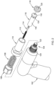
- a tool 100 for installing a blind fastener includes a handle 102, a nutrunner or automation interface 104, a stationary nut 106, a first compression spring 108, an external sleeve 110, a second compression spring 112, a stem ejector 114, a collet 116, and a nose piece 118.
- the nose piece 118 defines a handling member receiving space 120 for receiving a nut head of a blind fastener and functions as a double action attachment, which will be described in more detail later.
- the nutrunner 104 has a driving end 122 for driving the collet 116, and a head portion 124 for engaging the stationary nut 106.
- the driving end 122 has outer threads for engaging inner threads of the collet 116.
- the head portion 124 includes outer threads for engaging inner threads of the stationary nut 106 so that the stationary nut 106 is secured to the nut runner 104.
- the collet 116 is connected to the driving end 122 and rotationally driven by the driving end 122.
- the collet 116 has a cylindrical portion 130, an enlarged portion 132, and a driving hex 134 disposed therebetween.
- the nosepiece 118 is mounted to an end of the external sleeve 110 and defines a handling member receiving space 120 therein.
- the nosepiece 118 and the external sleeve 110 may be integrally formed as a one-piece component as shown in FIGS. 4 and 5 .
- the external sleeve 110 includes a cylindrical portion 135, an enlarged portion 136, a first hex socket 138 disposed in the enlarged portion 136, and a shoulder 142 extending radially from an inner surface of the cylindrical portion 135.
- the inner surface of the shoulder 142 defines a second hex socket 140.
- the inner surface of the cylindrical portion 135 further defines inner threads 144 so that the nosepiece 118 can be attached to the cylindrical portion 135 of the external sleeve 110 in a threaded connection. While the sockets 138 and 140 and driving hex 134 are described and shown as hexagonal shaped, other shapes can be used.
- the second hex socket 140 is configured to engage the driving hex 134 of the collet 116 when the external sleeve 110 is moved to a first position (shown in FIG. 6 ) so that the external sleeve 110 can be driven by the collet 116 to rotate with the collet 116.
- the first hex socket 138 is configured to surround and engage the stationary nut 106 when the external sleeve 110 is moved to a second position (shown in FIG. 7 ) so that the external sleeve 110 remains stationary.
- the collet 116 has a first end engaging the driving end 122 of the nutrunner 104 and a second end configured to engage a core bolt 3 of a blind fastener 30.
- the second end of the collet 116 defines an aperture 115 open through the second end that has a shape that is configured to grip and rotate the front end 13 of the core bolt 3.
- the front end 13 of the core bolt 3 includes a plurality of flat surfaces configured to be engaged by a plurality of mating flat surfaces within the aperture 115.
- the collet 116 defines an internal space for receiving the second compression spring 112 and the stem ejector 114 therein.
- the second compression spring 112 is disposed around a rear portion of the stem ejector 114 and abuts a forward portion of the stem ejector 114 to bias the stem ejector forward (i.e., away from the first end of the collet 116.
- the forward portion of the stem ejector 114 is configured to be received in the aperture 115 and positioned so that the front end 13 of the core bolt 3 axially displaces the stem ejector 114 when the front end 13 is received in the aperture 115.
- the first compression spring 108 is disposed around the cylindrical portion 130 of the collet 116 and between the shoulder 142 and the stationary nut 106.
- the external sleeve 110 and the nose piece 118 may be formed as a one-piece component so that the external sleeve 110 also defines a handling member receiving space 120.
- the first compression spring 108 is disposed at one side of the shoulder 142 and the enlarged head 132 of the collet 116 is disposed on the other side of the shoulder 142.
- the first compression spring 108 is configured to bias the external sleeve 110 forward relative to the stationary nut 106.
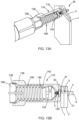
- the external sleeve 110 is movable relative to the collet 116 along a longitudinal axis of the collet 116 between a first position (shown in FIGS. 4-6 ) where the second hex socket 140 engages the driving hex 134 of the collet 116 and the first hex socket 138 is disengaged from the stationary nut 106 and a second position (shown in FIG. 7 ) where the second hex socket 140 of the external sleeve 110 is disengaged from the driving hex 134 of the collet 116 and the first hex socket 138 of the external sleeve 110 engages the stationary nut 106.
- the tool 100 is operable in two operating modes: in the first operating mode, the external sleeve 110 is moved away from the stationary nut 106 along the longitudinal direction of the collet 116 to the first position where the second hex socket 140 engages the driving hex 134, as shown in FIG. 6 . By this engagement, the external sleeve 110 can be driven by the collet 116 to rotate together with the collet 116. In the second operating mode, the external sleeve 110 is moved toward the stationary nut 106 to the second position where the first hex socket 138 of the external sleeve 110 engages the stationary nut 106, as shown in FIG. 7 .
- the second hex socket 140 of the external sleeve 110 is disengaged from the driving hex 134 of the collet 116. Therefore, the external sleeve 110 remains stationary despite the rotating action of the collet 116.
- the first compression spring 108 is compressed between the stationary nut 106 and the internal shoulder 142 to bias the internal shoulder in the axial direction away from the stationary nut 106.
- the force that pushes the external sleeve 110 to the stationary nut 106 is released (e.g., the external sleeve is no longer pressed against a workpiece 1), the first compression spring 108 can push the external sleeve 110 back to the first position.
- the tool 100 is configured to install a blind fastener 30 shown in FIGS. 8 to 10 .
- the blind fastener 30 can be similar to the blind fastener described and shown in co-pending and commonly assigned U.S. Patent Application No. 16/201,919 .
- the blind fastener 30 is configured to connect a plurality of panels including a front panel 1 and a rear panel 2, and is configured to be inserted into a countersunk hole 31 of the front and rear panels 1 and 2.
- the blind fastener 30 includes a core bolt 3, a core nut 5 surrounding a middle portion of the core bolt 3, and a sleeve 4 surrounding a rear portion of the core bolt 3.
- the rear portion of the core bolt 3 defines a smooth section 32, and the front portion and the middle portion of the core bolt 3 defines a threaded section 34.
- a core bolt stop shoulder 10 may be defined between the smooth section 32 and the threaded section 34 of the core bolt 3.
- the smooth section 32 of the core bolt 3 has an outer peripheral surface constituting a smooth rotational surface 12.
- the threaded section 34 of the core bolt 3 includes outer threads and a break-off notch 14 adjacent to the core bolt stop shoulder 10.
- the break-off notch 14 constitutes a weaker point at the core bolt 3 so that the core bolt 3 can be broken at the break-off notch 14 after the blind fastener 3 is completely installed in the panels 1 and 2.
- the break-off notch 14 is positioned such that it is aligned with the front side 16 of the front panel 1 when the stop shoulders are engaged 10, 15 so that it will break off flush with or recessed from the front side 16 of the front panel 1.
- the core bolt 3 further includes a core bolt head 9 at a rear end of the core bolt 3.
- the core bolt head 9 is disposed outside the sleeve 4 and defines a recess 8 that facilitates a removal process of the fastener 30 at the end of the product lifecycle by drilling out the fastener 30.
- the sleeve 4 has a tubular configuration and includes an inner peripheral surface 11 constituting a smooth rotational surface 11 in contact with the smooth rotational surface 12 of the core bolt 3.
- the smooth rotational surface 12 of the core bolt 3 and the smooth rotational surface 11 of the sleeve 4 function as rotating bearing surfaces, which may be lubricated, when a front end 13 of the core bolt 3 is tightened or loosened to move the core bolt 3 relative to the core nut 5.
- the core nut 5 has a tubular configuration and includes a main body 40, a nut head 41, and a handling member 42.
- the nut head 41 extends radially outward from one end of the main body 40 to have a larger outside diameter than the main body 40.
- the nut head 41 is between the handling member 42 and the main body 40.
- a peripheral groove 52 (shown in FIG. 9 ) is defined between the nut head 41 and the handling member 42.
- the nut head 41 is configured to be held by the tool 100 of FIGS. 1 to 2 during installation of the fastener 30 to prevent the core nut 5 from rotating when the core bolt 3 is screwed into or out of the core nut 3.
- the main body 40 and nut head 41 of the core nut 5 are disposed in the countersunk hole 13 of the front and rear panels 1 and 2.
- the handling member 42 is disposed outside the front and rear panels 1 and 3.
- the peripheral groove 52 between the handling member 42 and the nut head 41 functions as a break-off groove to allow the handling member 42 to break off after the fastener 30 is completely installed.
- the threaded part 74 of the core nut 3 is threadedly engaged to the threaded section 34 of the core bolt 3.
- the break-off notch 14 of the core bolt 3 is disposed away from the front surface 16 of the front panel 1, and the core bolt stop shoulder 10 is disposed away from the core nut stop shoulder 15 of the core nut 5.
- the end surface 82 of the nut head 41 of the core nut 5 and the break-off groove 52 of the core nut 5 are flush with the front surface 16 of the front panel 1.
- the core bolt head 9 is moved towards the core nut 5 until the core bolt stop shoulder 10 comes to a positive stop and abuts against the core nut stop shoulder 15. Concurrently, the break-off notch 14 is moved to be flush with the front surface 16 of the front panel 1 and the end surface 82 of the core nut 3. The break-off groove 52 is also flush with the front surface 16 of the front panel 1. It is understood that that core bolt stop shoulder 10 and the core nut stop shoulder 15 are optional and do not have to be present in the blind fastener 30 to create flush surfaces in the blinder fastener 30 after the blind fastener is completely installed. As the core bolt 3 is tightened and the core bolt head 9 is moved toward the core nut 5, the sleeve 4 is compressed and deformed by the core bolt head 9 to form a bulb portion 21.
- the threaded front portion of the core bolt 3 may break off at the break-off notch 14. A flush surface is thus formed on the core bolt 3. Also, by applying torsional force on the core nut 5, the handling member 42 breaks off at the break-off groove 52 and thus another surface 82 is formed on the core nut 5 to be flush with the front surface 16 of the front panel 1.
- a three-step process is typically required.
- a first tool (not shown) is used to screw out the core bolt 3 from the core nut 5 to form the bulb portion 21 while the handling portion 42 of the core nut 5 is held by a second tool (not shown).
- the front portion 13 of the core bolt 3 is broken off by rotating the first tool further.
- the handling portion 42 of the core nut 5 is broken off by rotating the second tool to generate surfaces flush with the front panel 1.
- the blind fastener 30 may be installed in the panels 1 and 2 by using the single tool 100 of FIGS. 1 and 2 .
- the tool 100 of the present disclosure can be used to achieve a double action by installing the fastener while holding the handling portion 42 stationary and then automatically shifting the torque to the handling portion 42 to break handling portion 42 off the core nut 5.
- the blind fastener 30 may be first inserted into the countersunk hole in the panels.
- the tool 100 is operated in the first operating mode where the first compression spring 108 is in its released state and the second hex socket 140 of the external sleeve 110 engages the driving hex 134 of the collet 116.
- the external sleeve 110 rotates with the collet 116.
- the external sleeve 110 is in the first position.
- both the collet 116 and the external sleeve 110 can apply a torque to the fastener 30.
- the tool 100 is moved closer to the front panel 1 so that the front end 13 of the core bolt 3 is received in the aperture 115 of the collet 116 to be gripped by the collet 116 for rotation therewith and the handling portion 42 is received in the handling member receiving space 120 to be gripped by the nose piece 118.
- the external sleeve 110 is moved relative to the collet 116 to the second position to engage the stationary nut 106.
- the external sleeve 110 also contacts the front panel 1 in the second position.
- the tool 100 is operated in the second operating mode where the external sleeve 110 is not driven by the collet 116.
- the core bolt 3 of the fastener 30 is driven by the collet 116 and the external sleeve 110 holds the handling member 42 of the core nut 5 so that the core nut 5 does not rotate while the core bolt 3 is screwed out of the core nut 5.
- torque is applied by the collet 116 to the core bolt 3.
- moving the tool 100 away from the front panel 1 causes the external sleeve 110 to be pushed back to the first positon by the first compression spring 108 so that the second hex socket 142 of the external sleeve 110 engages the driving hex 134 of the collet 116 and the external sleeve 110 rotates with the collet 116.
- the full torque rotation of the external sleeve 110 causes shearing off the handling portion 42, generating a flush surface on the core nut 5.
- the handling portion 42 and the front end of the core bolt 3 remain inside the external sleeve 110 and the nose piece 118.
- the nutrunner 104 can be stopped. Once the nutrunner 104 is stopped, the second compression spring 112 pushes the stem ejector 114, which in turn pushes the front end of the core bolt 3 and the handling member 42 out of the external sleeve 110 and the nose piece 118.
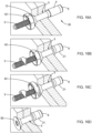
- the fastener is first placed in the countersunk hole 13 of the panels as shown in FIG. 16A .
- a torsional force is applied by the collet 116 of the tool 100 to the core bolt 3 to screw the core bolt 3 out of the core nut 5 as shown in FIG. 16B .
- the handling portion 42 is held by the external sleeve 110 of the tool 100, which is stationary in the second operating mode, to prevent the core nut 5 from rotating when the core bolt 3 is screwed relative to the core nut 5.
- the external sleeve 110 of the tool 100 is moved to the first position and tool 100 is operated in the first operating mode.
- the collet 116 of the tool 100 continues to apply the torsional force to the core bolt 3 and the external sleeve 110 starts to apply a torsional force to the handling member 42 as shown in FIG. 16C .
- the torsional force applied by the external sleeve 110 to the handling member 42 is greater than the torsional force applied by the collet 116 to the core bolt 3.
- the torsional force by the external sleeve 110 and the collet 116 will cause the handling member 42 and the front end of the core bolt 3 to break off, thereby forming flush surfaces on the core bolt 3 and the core nut 5, as shown in FIG. 16D .
- the installation process by the tool is automatic, making the typically three-step installation process an automatic dual-action installation process.
- the tool 100 may use a typical nutrunner or an automation end-effector with minor changes, such as pneumatic or electric nutrunners or end-effectors for example.
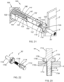
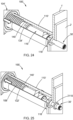
- FIGS. 17-21 a tool 100' of a second construction is illustrated.
- the tool 100' is similar to the tool 100 ( FIGS. 1-7 and 11A-15B ), except as otherwise shown or described herein.
- Features of tool 100' that are similar to features of tool 100 ( FIGS. 1-7 and 11A-15B ) are identified with similar, but primed reference numerals, and only differences are described in detail herein.
- the tool 100' is configured to install a blind fastener 30' of a second construction.
- the blind fastener 30' includes a bolt 3' and a nut 5'.
- the bolt 3' is a single, unitarily formed piece and the nut 5' is a single unitarily formed piece.
- the blind fastener 30' is described in greater detail in U.S. Patent Application No. 16/201,775 .
- the bolt 3' includes a first handling portion 1710, a bolt head 1714, and a shaft 1718.
- One end of the shaft 1718 includes external threads, while the opposite end of the shaft is coupled to the bolt head 1714.
- the bolt head 1714 extends radially outward from the shaft 1718.
- a first frangible portion 1722 of the bolt 3' couples the first handling portion 1710 to the bolt head 1718.
- the first frangible portion 1722 is configured to break off so that the end of the bolt head 1714 is flush with or recessed from the forward surface of the front panel 1' when a torque applied to the handling portion 1710 exceeds a first threshold.
- the nut 5' includes a second handling portion 1726, a nut head 1730, and a sleeve 1734.
- the sleeve defines a central bore that extends axially through the nut 5'.
- One end of the sleeve 1734 includes internal threads configured to matingly engage the external threads of the bolt 3', while the opposite end of the sleeve 1734 is coupled to the nut head 1730.
- the nut head 1730 extends radially outward from the sleeve 1734.
- the nut head 1730 defines a recess in which the bolt head 1714 is received so that the end surface of the bolt head 1714 is flush or recessed relative to the end surface of the nut head 1730.
- the nut head 1730 is configured to be received in the counterbored hole of the panels 1' and 2' so that the end surface of the nut head 1730 is flush or recessed relative to the forward surface of the front panel 1'.
- a second frangible portion 1738 couples the second handling portion 1726 to the nut head 1730.
- the second frangible portion 1738 is configured to break off so that the end of the nut head 1730 is flush with or recessed from the forward surface of the front panel 1' when a torque applied to the handling portion 1710 exceeds a second threshold.
- the second threshold can be greater than the first threshold.
- the second handling portion 1726 surrounds a portion of the first handling portion 1710.
- the collet 116' of the tool 100' has an aperture 115' having a predetermined shape that is configured to engage a mating predetermined shape of the first handling portion 1710 of the bolt 3' to rotate the bolt 3'.
- the nose 118' of the tool 100' has a handling member receiving space 120' having a predetermined shape that is configured to engage a mating predetermined shape of the second handling portion 1726.
- the handling member receiving space 120' is a 12 point star shape that can engage a hexagonal or other shape of the second handling portion 1726, though other shapes can be used for the handling member receiving space 120' or the second handling portion 1726.
- the second socket 140' is also a 12 point star shape configured to engage the hexagonal shape of the driving hex 134', though other shapes can be used for the second socket 140' and the driving feature 134'.
- the driving hex 134' also includes angular or helical ramps 134'a that angle from the rear side of each point of the hex shape, downward toward the cylindrical surface.
- the ramps 134'a are also angled axially.
- each ramp 134'a can have a leading portion 134'b and a trailing portion 134'c with the leading portion 134'b being axially forward of the trailing portion 134'c and ramps radially outward until meeting the rest of the hexagonal feature (e.g., the hex-flats or the point).
- These ramps 134'a can aid in rapid engagement of the driving hex 134' with the second socket 140' without the need for perfect alignment of the two features.
- the bolt 3' is threaded into the nut 5' until the bolt head 1714 is received in the nut head 1730, as shown in FIG. 23 , so that the blind fastener 30' is in a pre-installed condition.
- the blind fastener 30' is then inserted into the countersunk bore of the panels 1' and 2' until the nut head 1730 is flush with the front panel 1'. In this position, the first and second handling portions 1710 and 1726 extend from the front panel 1'. As shown in FIG.
- the tool before the tool 100' engages the fastener 30', the tool is in the first operating condition, with the first spring 108' biasing the collet 116' forward so that the driving hex 134' of the collet 116' engages the second socket 140' of the external sleeve 110'.
- the collet 116' is in the first position and rotates with the external sleeve 110'.
- the tool 100' is moved forward so that the second handling portion 1726 is received in and engaged by the nose 118'.
- the tool 100' is moved further forward and the nose 118' abuts the front panel 1' and is pushed rearward relative to the collet 116' until in the second position shown in FIG. 24 .
- the driving hex 134' is disengaged from the second socket 140'.
- the nut runner 104 instead of the external stationary nut 106 ( FIG. 4 ), the nut runner 104 has a stationary nut 106' that defines an internal feature configured to mate with an external feature of the external sleeve 110'.
- the internal feature is radially inward extending internal lugs 106'a, though other configurations can be used (e.g., internal hex or splines), and the external feature are axially extending lugs 138', though other mating configurations can be used.
- the internal feature of the stationary nut 106' is disengaged from the external feature of the external sleeve 110'.
- the second position FIG. 24
- the internal feature of the nut 106' is engaged with the external feature of the external sleeve 110' so that the external sleeve 110' is held rotationally stationary.
- the tool 100' can be operated in the second operating mode wherein only the collet 116' rotates.
- the external sleeve 110' holds the nut 5' rotationally stationary while the collet 116' rotates the bolt 3' until a bulb 2110 ( FIG. 22 ) is formed in the sleeve 1734 on the back side of the rear panel 2'.
- the torque imparted on the bolt 3' by the collet 116' can exceed the first threshold to break off the first handling portion 1710.
- the tool 100' can be retracted.
- the first spring 108' biases the external sleeve 110' until in the first position so that the stationary nut 106' is disengaged from the exterior sleeve 110' and the driving hex 134' of the collet 116' engages the second socket 140' of the external sleeve 110' so that the collet 116' and the external sleeve 110' rotate together.
- the nose 118' is still engaged with the second handling portion 1726.
- the collet 116' rotates the exterior sleeve 110' further until a torque applied to the second handling portion 1726 of the nut 5' exceeds the second threshold torque to break off the second handling portion 1726 from the nut head 1730.
- the tool 100' is retracted further and the second spring 112' pushes the stem ejector 114' forward in the collet 116' so that the stem ejector 114' ejects the first and second handling portions 1710 and 1726 from the tool 100'.
Landscapes
- Engineering & Computer Science (AREA)
- Mechanical Engineering (AREA)
- General Engineering & Computer Science (AREA)
- Dowels (AREA)
- Gripping On Spindles (AREA)
- Insertion Pins And Rivets (AREA)
- Portable Nailing Machines And Staplers (AREA)
Claims (13)
- Werkzeug (100, 100') zum Installieren einer Blindbefestigung (30, 30'), die einen Kernbolzen (3, 3') und eine Kernmutter (5, 5') einschließt, wobei das Werkzeug (100, 100') Folgendes umfasst:ein Antriebselement (122, 122');eine durch das Antriebselement (122, 122') angetriebene Spannzange (116, 116'), die so konfiguriert ist, dass sie in den Kernbolzen (3, 3') eingreift; undeine äußere Hülse (110, 110'), die so konfiguriert ist, dass sie die Kernmutter (5, 5') hält und so konfiguriert ist, dass sie die Rotation der Kernmutter (5, 5') während der Installation der Blindbefestigung (30, 30') verhindert, wobei das Werkzeug gekennzeichnet ist durch:
die äußere Hülse (110, 110'), die zwischen einer ersten Position, in der die äußere Hülse (110, 110') von der Spannzange (116, 116') angetrieben wird, um sich mit der Spannzange (116, 116') zu drehen, und einer zweiten Position, in der die äußere Hülse (110, 110') trotz der Rotationswirkung der Spannzange (116, 116') stationär ist, beweglich ist. - Werkzeug (100, 100') nach Anspruch 1, das ferner einen Schraubendreher (104, 104') umfasst, wobei das Antriebselement (122, 122') ein Teil des Schraubendrehers (104, 104') ist.
- Werkzeug (100, 100') nach Anspruch 1 oder Anspruch 2, wobei die äußere Hülse (110, 110') eine erste Buchse (120, 120', 138) und eine zweite Buchse (140, 140') einschließt.
- Werkzeug (100) nach Anspruch 3, das ferner eine stationäre Mutter (106) umfasst, wobei die zweite Buchse (140) der äußeren Hülse (110) in die Spannzange (116) eingreift, wenn die äußere Hülse (110) in der ersten Position ist, und die erste Buchse (138) der äußeren Hülse (110) in die stationäre Mutter (106) eingreift, wenn die äußere Hülse (110) in der zweiten Position ist.
- Werkzeug (100, 100') nach einem der Ansprüche 1 bis 4, wobei die Spannzange (116, 116') einen zylindrischen Abschnitt (130, 130'), einen vergrößerten Abschnitt (132, 132') und ein dazwischen angeordnetes Antriebsmerkmal (134, 134') einschließt, und
wobei die Spannzange (116, 116') mit dem Antriebselement (122, 122') verbunden ist und von dem Antriebselement (122, 122') rotierend angetrieben wird, wobei das Antriebselement (122, 122') äußere Gewinde definiert, die in innere Gewinde der Spannzange (116, 116') eingreifen. - Werkzeug (100') nach Anspruch 5, wobei das Antriebsmerkmal (134') eine Vielzahl von winkelförmigen oder schraubenförmigen Rampen (134'a) definiert, die von der Rückseite jedes Punktes des Antriebsmerkmals (134') nach unten in Richtung des zylindrischen Abschnitts (130') abgewinkelt und so konfiguriert sind, dass sie den Eingriff des Antriebsmerkmals (134') in eine Buchse (140') der äußeren Hülse (110') unterstützen.
- Werkzeug (100') nach Anspruch 1, ferner umfassend eine stationäre Mutter (106'), die ein inneres Merkmal (106'a) definiert, das so konfiguriert ist, dass es mit einem äußeren Merkmal (138') der äußeren Hülse (110') zusammenpasst, wobei in der ersten Position das innere Merkmal (106'a) der stationären Mutter (106') von dem äußeren Merkmal (138') der äußeren Hülse (110, 110') gelöst ist und in der zweiten Position, das innere Merkmal (106'a) der stationären Mutter (106') mit dem äußeren Merkmal (138') der äußeren Hülse (110') in Eingriff steht und ein Antrieb (134') der Spannzange (116') von einer Buchse (140') der äußeren Hülse (110') gelöst ist, und wobei eine Nase (118') der äußeren Hülse (110') so konfiguriert ist, dass sie einen Handhabungsabschnitt (1726) der Kernmutter (5') aufnimmt und damit in Eingriff steht.
- Werkzeug (100') nach Anspruch 7, wobei das innere Merkmal (106'a) der stationären Mutter (106') ein Satz von ersten Laschen (106'a) ist, die sich radial nach innen erstrecken, und das äußere Merkmal (138') der äußeren Hülse (110') ein Satz von zweiten Laschen (138') ist, die sich axial erstrecken.
- Werkzeug nach Anspruch 1, ferner umfassend eine erste Feder (108, 108'), die um einen zylindrischen Abschnitt (130, 130') der Spannzange (116, 116') zwischen einer Schulter (142, 142') der äußeren Hülse (110, 110') und der stationären Mutter (106, 106') angeordnet ist, wobei die erste Feder (108, 108') konfiguriert ist, um die äußere Hülse (110, 110') relativ zur stationären Mutter (106, 106') in Richtung der ersten Position vorzuspannen, wobei die erste Feder (108, 108') auf einer Seite der Schulter (142, 142') angeordnet ist und ein vergrößerter Kopf (132, 132') der Spannzange (116, 116') auf der anderen Seite der Schulter (142, 142') angeordnet ist.
- Werkzeug nach Anspruch 1, ferner umfassend eine Feder (112, 112') und einen Schaftauswerfer (114, 114'), wobei ein erstes Ende der Spannzange (116, 116') so konfiguriert ist, dass es in das Antriebselement (122, 122') eingreift, und ein zweites Ende der Spannzange (116, 116') eine durch das zweite Ende offene Aussparung (115, 115') definiert, die eine Form aufweist, die so konfiguriert ist, dass sie ein vorderes Ende (13, 13') des Kernbolzens (3, 3') greift und dreht, wobei die Feder (112, 112') und der Schaftauswerfer (114, 114') innerhalb eines durch die Spannzange (116, 116') definierten inneren Raums angeordnet sind, wobei die Feder (112, 112') um einen hinteren Abschnitt des Schaftauswerfers (114, 114') herum angeordnet ist und einen vorderen Abschnitt des Schaftauswerfers (114, 114') abstützt, um den Schaftauswerfer (114, 114') in der Spannzange (116, 116') nach vorne zu drücken, sodass der vordere Abschnitt des Schaftauswerfers (114, 114') in der Aussparung (115, 115') aufgenommen wird und einen Handhabungsabschnitt (1710) des Kernbolzens (3, 3') und einen Handhabungsabschnitt (42, 1726) der Kernmutter (5, 5') aus dem Werkzeug (100, 100') auswirft.
- Verfahren zum Installieren einer Blindbefestigung (30'), einschließlich eines Bolzens (3') und einer Mutter (5'), das Verfahren umfassend:Bereitstellen des Werkzeugs (100') nach Anspruch 7 und 9, wobei sich das Werkzeug (100') in einem ersten Betriebszustand befindet, in dem sich die äußere Hülse (110') in der ersten Position befindet, wobei eine Feder (108') die Spannzange (116') nach vorne in Richtung der ersten Position vorspannt, wobei in der ersten Position ein Antrieb (134') der Spannzange (116') in eine Buchse (140') der äußeren Hülse (110') eingreift, sodass die Spannzange (116') und die äußere Hülse (110') zusammen rotieren;Bewegen des Werkzeugs (100') nach vorne, sodass ein Handhabungsabschnitt (1726) der Kernmutter (5') von einer Nase (118') der äußeren Hülse (110') aufgenommen wird und in diese eingreift;Bewegen des Werkzeugs (100') weiter nach vorne, bis die Nase (118') an einer Frontplatte (1') anstößt und die Nase (118') relativ zur Spannzange (116') nach hinten gedrückt wird und die äußere Hülse (110') sich in der zweiten Position befindet, wobei in der zweiten Position, der Antrieb (134') von der Buchse (140') gelöst ist und eine stationäre Mutter (106') des Werkzeugs (100') in die äußere Hülse (110') eingreift, um eine Rotation der äußeren Hülse (110') zu verhindern, wobei in der ersten Position die stationäre Mutter (106') von der äußeren Hülse (110') gelöst ist;Betreiben des Werkzeugs mit der äußeren Hülse (110') in der zweiten Position, sodass die äußere Hülse (110') die Mutter (5') drehfest hält, während die Spannzange (116') den Bolzen (3') dreht, bis ein Wulst (2110) in einer Hülse (1734) der Mutter (5') gebildet wird;Ausüben eines Drehmoments auf den Bolzen (3') durch die Spannzange (116'), bis ein Handhabungsabschnitt (1710) des Bolzens (3') abbricht;Zurückziehen des Werkzeugs (100'), bis sich die äußere Hülse (110') in der ersten Position befindet, in der die Nase (118') noch mit dem Handhabungsabschnitt (1726) der Kernmutter (5') in Eingriff steht;Rotieren der Spannzange (116'), um die Hülse (110, 110') zu drehen, bis der Handhabungsabschnitt (1726) der Mutter (5') abbricht.
- Verfahren nach Anspruch 11, wobei das Werkzeug (100') eine zweite Feder (112') und einen Schaftauswerfer (114') einschließt, wobei ein erstes Ende der Spannzange (116') so konfiguriert ist, dass es in das Antriebselement (122') eingreift, und ein zweites Ende der Spannzange (116') eine durch das zweite Ende offene Aussparung (115') definiert, die eine Form aufweist, die so konfiguriert ist, dass sie ein vorderes Ende (13') des Kernbolzens (3') greift und rotiert, wobei die zweite Feder (112') und der Schaftauswerfer (114, 114') innerhalb eines durch die Spannzange (116') definierten inneren Raums angeordnet sind, die zweite Feder (112') um einen hinteren Abschnitt des Kernbolzens (114') herum angeordnet ist und einen vorderen Abschnitt des Kernbolzens (114') abstützt, um den Kernbolzen (114') in der Spannzange (116') nach vorne zu drücken, sodass der vordere Abschnitt des Kernbolzens (114') in der Aussparung (115') aufgenommen wird und so konfiguriert ist, dass der Handhabungsabschnitt (1710) des Kernbolzens (3') und der Handhabungsabschnitt (1726) der Kernmutter (5') aus dem Werkzeug (100') ausgeworfen werden, wobei das Verfahren ferner umfasst, dass das Werkzeug (100') weiter zurückgezogen wird und die Handhabungsabschnitte (1710, 1726) des Kernbolzens (3') und der Kernmutter (5') aus dem Werkzeug (100') ausgeworfen werden.
- Werkzeug (100') nach Anspruch 5, wobei die Spannzange (116') eine Aussparung (115') aufweist, die eine vorbestimmte Form aufweist, die so konfiguriert ist, dass sie in eine passende vorbestimmte Form eines ersten Handhabungsabschnitts (1710) des Kernbolzens (3') eingreift, um den Bolzen (3') zu rotieren, wobei der Bolzen (3') einen Bolzenkopf (1714) und einen Schaft (1718) einschließt, von dem ein Ende ein äußeres Gewinde einschließt, während das gegenüberliegende Ende des Schafts mit einem Bolzenkopf (1714) gekoppelt ist, der sich vom Schaft (1718) radial nach außen erstreckt,der Bolzen (3') einen ersten abbrechbaren Abschnitt (1722) einschließt, der einen ersten Handhabungsabschnitt (1710) mit dem Bolzenkopf (1718) koppelt, wobei der erste abbrechbare Abschnitt (1722) so konfiguriert ist, dass er abbricht, sodass das Ende des Bolzenkopfes (1714) mit der vorderen Oberfläche einer Frontplatte (T) bündig oder ausgespart ist, wenn ein auf den Handhabungsabschnitt (1710) aufgebrachtes Drehmoment einen ersten Schwellenwert überschreitet,und das Werkzeug (100') eine Nase (118') einschließt, die einen Raum (120') zur Aufnahme eines Handhabungselements definiert, der eine vorbestimmte Form aufweist, die so konfiguriert ist, dass sie mit einer passenden vorbestimmten Form eines zweiten Handhabungsabschnitts (1726) der Kernmutter (5') eingreift, wobei die Kernmutter (5') einen Mutterkopf (1730) und eine Hülse (1734) einschließt, die eine zentrale Bohrung definiert, die sich axial durch die Kernmutter (5') erstreckt und ein inneres Gewinde einschließt, das so konfiguriert ist, dass es mit dem äußeren Gewinde des Bolzens (3') zusammenpasst, wobei ein gegenüberliegendes Ende der Hülse (1734) mit dem Mutterkopf (1730) gekoppelt ist, wobei sich die Mutternköpfe von der Hülse (1734) radial nach außen erstrecken und eine Aussparung definieren, in der der Bolzenkopf (1714) aufgenommen wird, sodass eine Endoberfläche des Bolzenkopfes (1714) relativ zur Endoberfläche des Mutternkopfes (1730) bündig oder ausgespart ist, wobei der Mutternkopf (1730) so konfiguriert ist, dass er in dem gesenkten Loch von Platten (T, 2') aufgenommen wird, sodass die Endoberfläche des Mutternkopfes (1730) relativ zur vorderen Oberfläche einer Frontplatte (1') bündig oder ausgespart ist, wobei ein zweiter abbrechbarer Abschnitt (1738) konfiguriert ist, um den zweiten Handhabungsabschnitt (1726) mit dem Mutterkopf (1730) zu koppeln, wobei der zweite abbrechbare Abschnitt (1738) konfiguriert ist, um abzubrechen, sodass das Ende des Mutterkopfs (1730) mit der vorderen Oberfläche der Frontplatte (T) bündig oder ausgespart ist, wenn ein auf den Handhabungsabschnitt (1710) aufgebrachtes Drehmoment einen zweiten Schwellenwert überschreitet,wobei der zweite Handhabungsabschnitt (1726) einen Abschnitt des ersten Handhabungsabschnitts (1710) umgibt,wobei die äußere Hülse (110') eine Buchse (140') einschließt, die eine Form aufweist, die so konfiguriert ist, dass sie in eine passende Form des Antriebsmerkmals (134') eingreift, und wobei das Antriebsmerkmal ein Antrieb (134') ist.
Applications Claiming Priority (2)
| Application Number | Priority Date | Filing Date | Title |
|---|---|---|---|
| US201762591617P | 2017-11-28 | 2017-11-28 | |
| PCT/US2018/062921 WO2019108703A1 (en) | 2017-11-28 | 2018-11-28 | Automatic double-action fastener installation tool |
Publications (3)
| Publication Number | Publication Date |
|---|---|
| EP3717145A1 EP3717145A1 (de) | 2020-10-07 |
| EP3717145C0 EP3717145C0 (de) | 2023-06-07 |
| EP3717145B1 true EP3717145B1 (de) | 2023-06-07 |
Family
ID=64746649
Family Applications (1)
| Application Number | Title | Priority Date | Filing Date |
|---|---|---|---|
| EP18822559.3A Active EP3717145B1 (de) | 2017-11-28 | 2018-11-28 | Automatisches doppeltwirkendes werkzeug zur installation von befestigungselement |
Country Status (7)
| Country | Link |
|---|---|
| US (1) | US10974310B2 (de) |
| EP (1) | EP3717145B1 (de) |
| CN (1) | CN111372702B (de) |
| BR (1) | BR112020010704B1 (de) |
| CA (1) | CA3081901C (de) |
| MX (1) | MX387757B (de) |
| WO (1) | WO2019108703A1 (de) |
Families Citing this family (13)
| Publication number | Priority date | Publication date | Assignee | Title |
|---|---|---|---|---|
| USD913782S1 (en) * | 2019-06-07 | 2021-03-23 | Sps Technologies, Llc | Blind fastener sleeve |
| WO2021041508A1 (en) | 2019-08-26 | 2021-03-04 | Sps Technologies, Llc | Two-piece blind fastener and installation tool |
| USD909857S1 (en) | 2019-08-27 | 2021-02-09 | Sps Technologies, Llc | Blind fastener bolt head |
| USD920774S1 (en) | 2019-08-27 | 2021-06-01 | Sps Technologies, Llc | Blind fastener |
| USD909856S1 (en) | 2019-08-27 | 2021-02-09 | Sps Technologies, Llc | Blind fastener bolt |
| USD935877S1 (en) | 2019-08-27 | 2021-11-16 | Sps Technologies, Llc | Blind fastener nut |
| US11511399B2 (en) * | 2019-10-21 | 2022-11-29 | The Boeing Company | Methods and apparatus to remove frangible fastener remnants |
| EP4011558B1 (de) * | 2020-12-08 | 2024-10-09 | The Boeing Company | Verfahren und werkzeug zum anbringen eines befestigungselements |
| CA3142366C (en) | 2020-12-17 | 2023-11-07 | Sps Technologies, Llc | Two-piece blind fastener and installation tool |
| USD1121426S1 (en) | 2020-12-17 | 2026-04-07 | Sps Technologies, Llc | Blind fastener |
| CN113524102B (zh) * | 2021-06-17 | 2024-04-23 | 北京中纺精业机电设备有限公司 | 一种钢管固定装置及具有该装置的钢管接头元件拆装组件 |
| CN116214138B (zh) * | 2023-05-08 | 2023-10-17 | 莱芜职业技术学院 | 一种体育耗材自动组装设备 |
| ES2960190B2 (es) * | 2023-10-17 | 2024-11-08 | Loxin 2002 Sl | Herramienta para colocación automática de remaches manuales |
Family Cites Families (35)
| Publication number | Priority date | Publication date | Assignee | Title |
|---|---|---|---|---|
| US2415560A (en) | 1943-09-30 | 1947-02-11 | Bryant Heater Co | Rivet with fluid expander therein |
| US2789597A (en) * | 1955-01-03 | 1957-04-23 | Torre Joseph La | Driving and setting tool for blind fasteners |
| US2863351A (en) | 1956-02-20 | 1958-12-09 | Rudolph M Vaughn | Expanding fastener having threads of opposite hand to maintain the parts in engagement |
| US3253495A (en) | 1962-12-06 | 1966-05-31 | Huck Mfg Co | Hardened blind bolt with annealed shank portion |
| US3357094A (en) * | 1964-12-04 | 1967-12-12 | Nat Screw & Mfg Company | Blind fastener |
| IL42637A0 (en) * | 1973-07-01 | 1973-10-25 | Benimatzky E | Device for riveting blind rivets |
| DE2442292C2 (de) | 1974-09-04 | 1984-04-26 | Mecano-Simmonds Gmbh, 6900 Heidelberg | Blindniet |
| US4000668A (en) * | 1975-11-03 | 1977-01-04 | Keasler Ben C | Blind bolt fastener installation tool with an apparatus for retrieving severed blind bolt fastener stems |
| DE2744547A1 (de) | 1977-10-04 | 1979-04-12 | Schruff Herberts | Blindnietmutter |
| US4630510A (en) * | 1984-05-10 | 1986-12-23 | Monogram Industries, Inc. | Tactile engaging wrenching mechanism |
| GB2163823A (en) | 1984-08-31 | 1986-03-05 | Avdel Ltd | Self-plugging blind rivet |
| US5354160A (en) * | 1990-02-05 | 1994-10-11 | Textron Inc. | Composite fastener |
| GB2330639B (en) * | 1998-09-25 | 1999-10-13 | Milladale Ltd | Blind rivet and method of making the same |
| GB2368889B (en) | 2000-11-09 | 2004-02-04 | Textron Fastening Syst Ltd | Method of manufacturing a blind threaded insert |
| GB2383107B (en) | 2001-12-14 | 2004-10-27 | Emhart Llc | Improved blind rivet |
| US6761520B1 (en) | 2003-05-09 | 2004-07-13 | Pem Management, Inc. | Clinch-type blind nut |
| US6868757B2 (en) | 2003-05-20 | 2005-03-22 | Huck International, Inc. | Blind fastener and nose assembly for installation of the blind fastener |
| US7857563B2 (en) | 2006-02-28 | 2010-12-28 | Monogram Aerospace Fasteners, Inc. | Mechanically locked blind bolt fastener |
| FR2904385B1 (fr) | 2006-07-25 | 2008-09-05 | Garonne Ets Auriol & Cie | Procede de fixation structurelle par rivet aveugle, rivet aveugle permettant de le mettre en oeuvre et outil de pose adapte a un tel rivet |
| WO2009055298A2 (en) | 2007-10-22 | 2009-04-30 | Monogram Aerospace Fasteners, Inc. | Blind fastener |
| EP2713064A1 (de) * | 2008-04-02 | 2014-04-02 | Monogram Aerospace Fasteners, Inc. | Flächenbündiger Blindbefestiger |
| WO2012142033A2 (en) | 2011-04-14 | 2012-10-18 | Pratt John D | Fastener and method of installing same |
| US20130061452A1 (en) | 2011-09-14 | 2013-03-14 | John D. Pratt | Fastener and method of installing same |
| US8961086B2 (en) | 2011-09-14 | 2015-02-24 | John D. Pratt | Fastener and method of installing same |
| EP2758677A1 (de) | 2011-09-19 | 2014-07-30 | Monogram Aerospace Fasteners, Inc. | Blindbefestiger mit abnehmbarer schraubenschlüsselvorrichtung und verfahren zur entfernung der schraubenschlüsselvorrichtung |
| US9284971B2 (en) * | 2012-04-04 | 2016-03-15 | John D. Pratt | Fastener and method of installing same |
| ES2645622T3 (es) | 2012-04-17 | 2017-12-07 | Arconic Inc. | Dispositivo de fijación ciego |
| US8979453B2 (en) | 2012-04-17 | 2015-03-17 | Alcoa Inc. | Blind fastener |
| US9593706B2 (en) | 2012-11-11 | 2017-03-14 | The Boeing Company | Structural blind fastener and method of installation |
| CN203516322U (zh) | 2013-07-02 | 2014-04-02 | J·D·普拉特 | 紧固件 |
| FR3016417B1 (fr) | 2014-01-14 | 2016-01-22 | Lisi Aerospace | Rivet pour fixation aveugle, outil de pose associe et methode de pose d'un tel rivet |
| US20160102695A1 (en) | 2014-10-13 | 2016-04-14 | Monogram Aerospace Fasteners, Inc. | Deformable sleeve nut and a method of manufacturing |
| GB2531528A (en) * | 2014-10-20 | 2016-04-27 | Avdel Uk Ltd | Fastener installation tool |
| FR3037369B1 (fr) | 2015-06-11 | 2017-07-21 | Lisi Aerospace | Fixation installee d'un seul cote a douille deformable |
| FR3053745B1 (fr) | 2016-07-06 | 2019-05-17 | Lisi Aerospace | Rivet de fixation aveugle avec fut epaule et procede d'installation associe |
-
2018
- 2018-11-28 CA CA3081901A patent/CA3081901C/en active Active
- 2018-11-28 WO PCT/US2018/062921 patent/WO2019108703A1/en not_active Ceased
- 2018-11-28 MX MX2020005504A patent/MX387757B/es unknown
- 2018-11-28 BR BR112020010704-2A patent/BR112020010704B1/pt active IP Right Grant
- 2018-11-28 EP EP18822559.3A patent/EP3717145B1/de active Active
- 2018-11-28 CN CN201880074491.0A patent/CN111372702B/zh active Active
- 2018-11-28 US US16/203,535 patent/US10974310B2/en active Active
Also Published As
| Publication number | Publication date |
|---|---|
| CN111372702A (zh) | 2020-07-03 |
| US20190160520A1 (en) | 2019-05-30 |
| EP3717145C0 (de) | 2023-06-07 |
| BR112020010704B1 (pt) | 2022-03-15 |
| BR112020010704A2 (pt) | 2020-11-17 |
| CA3081901A1 (en) | 2019-06-06 |
| WO2019108703A1 (en) | 2019-06-06 |
| CA3081901C (en) | 2021-08-24 |
| CN111372702B (zh) | 2022-07-12 |
| EP3717145A1 (de) | 2020-10-07 |
| US10974310B2 (en) | 2021-04-13 |
| MX387757B (es) | 2025-03-18 |
| MX2020005504A (es) | 2021-11-10 |
| WO2019108703A4 (en) | 2019-07-25 |
Similar Documents
| Publication | Publication Date | Title |
|---|---|---|
| US10974310B2 (en) | Automatic double-action fastener installation tool | |
| EP1635994B1 (de) | Blindniet und nasenanordnung zur installation des blindniets | |
| EP1529170B1 (de) | Blindbefestiger und treibmutter sowie verfahren zur anwendung derselben | |
| JP3957146B2 (ja) | インサートおよびその取り付け方法 | |
| US20040022596A1 (en) | Fastener having integral drive nut | |
| EP2274121B1 (de) | Seitliche randansatzanordnung | |
| EP1327082B1 (de) | Blindbefestiger | |
| CN114729658A (zh) | 两件式单面紧固件和安装工具 | |
| EP1841552B1 (de) | Verfahren zur entfernung von blindhaltern | |
| US20250205775A1 (en) | Two-piece blind fastener installation tool | |
| US3025730A (en) | Driving tool for applying torque driven lockbolt fasteners | |
| EP1606069B1 (de) | Versetzte nasenanorndung mit verbessertem deflektor und verbesserten schutzanordnungen | |
| JP2006520691A5 (de) | ||
| CN121267087B (zh) | 应用于大底脚螺纹抽芯铆钉的铆接装置 | |
| EP4703595A1 (de) | Blindniet, setzgerät und verfahren |
Legal Events
| Date | Code | Title | Description |
|---|---|---|---|
| STAA | Information on the status of an ep patent application or granted ep patent |
Free format text: STATUS: UNKNOWN |
|
| STAA | Information on the status of an ep patent application or granted ep patent |
Free format text: STATUS: THE INTERNATIONAL PUBLICATION HAS BEEN MADE |
|
| PUAI | Public reference made under article 153(3) epc to a published international application that has entered the european phase |
Free format text: ORIGINAL CODE: 0009012 |
|
| STAA | Information on the status of an ep patent application or granted ep patent |
Free format text: STATUS: REQUEST FOR EXAMINATION WAS MADE |
|
| 17P | Request for examination filed |
Effective date: 20200611 |
|
| AK | Designated contracting states |
Kind code of ref document: A1 Designated state(s): AL AT BE BG CH CY CZ DE DK EE ES FI FR GB GR HR HU IE IS IT LI LT LU LV MC MK MT NL NO PL PT RO RS SE SI SK SM TR |
|
| AX | Request for extension of the european patent |
Extension state: BA ME |
|
| DAV | Request for validation of the european patent (deleted) | ||
| DAX | Request for extension of the european patent (deleted) | ||
| STAA | Information on the status of an ep patent application or granted ep patent |
Free format text: STATUS: EXAMINATION IS IN PROGRESS |
|
| 17Q | First examination report despatched |
Effective date: 20210712 |
|
| GRAP | Despatch of communication of intention to grant a patent |
Free format text: ORIGINAL CODE: EPIDOSNIGR1 |
|
| STAA | Information on the status of an ep patent application or granted ep patent |
Free format text: STATUS: GRANT OF PATENT IS INTENDED |
|
| INTG | Intention to grant announced |
Effective date: 20220706 |
|
| GRAJ | Information related to disapproval of communication of intention to grant by the applicant or resumption of examination proceedings by the epo deleted |
Free format text: ORIGINAL CODE: EPIDOSDIGR1 |
|
| STAA | Information on the status of an ep patent application or granted ep patent |
Free format text: STATUS: EXAMINATION IS IN PROGRESS |
|
| GRAP | Despatch of communication of intention to grant a patent |
Free format text: ORIGINAL CODE: EPIDOSNIGR1 |
|
| STAA | Information on the status of an ep patent application or granted ep patent |
Free format text: STATUS: GRANT OF PATENT IS INTENDED |
|
| INTC | Intention to grant announced (deleted) | ||
| INTG | Intention to grant announced |
Effective date: 20221123 |
|
| GRAS | Grant fee paid |
Free format text: ORIGINAL CODE: EPIDOSNIGR3 |
|
| GRAA | (expected) grant |
Free format text: ORIGINAL CODE: 0009210 |
|
| STAA | Information on the status of an ep patent application or granted ep patent |
Free format text: STATUS: THE PATENT HAS BEEN GRANTED |
|
| AK | Designated contracting states |
Kind code of ref document: B1 Designated state(s): AL AT BE BG CH CY CZ DE DK EE ES FI FR GB GR HR HU IE IS IT LI LT LU LV MC MK MT NL NO PL PT RO RS SE SI SK SM TR |
|
| REG | Reference to a national code |
Ref country code: GB Ref legal event code: FG4D |
|
| REG | Reference to a national code |
Ref country code: CH Ref legal event code: EP Ref country code: AT Ref legal event code: REF Ref document number: 1573465 Country of ref document: AT Kind code of ref document: T Effective date: 20230615 Ref country code: DE Ref legal event code: R096 Ref document number: 602018051409 Country of ref document: DE |
|
| U01 | Request for unitary effect filed |
Effective date: 20230706 |
|
| U07 | Unitary effect registered |
Designated state(s): AT BE BG DE DK EE FI FR IT LT LU LV MT NL PT SE SI Effective date: 20230718 |
|
| REG | Reference to a national code |
Ref country code: LT Ref legal event code: MG9D |
|
| PG25 | Lapsed in a contracting state [announced via postgrant information from national office to epo] |
Ref country code: NO Free format text: LAPSE BECAUSE OF FAILURE TO SUBMIT A TRANSLATION OF THE DESCRIPTION OR TO PAY THE FEE WITHIN THE PRESCRIBED TIME-LIMIT Effective date: 20230907 Ref country code: ES Free format text: LAPSE BECAUSE OF FAILURE TO SUBMIT A TRANSLATION OF THE DESCRIPTION OR TO PAY THE FEE WITHIN THE PRESCRIBED TIME-LIMIT Effective date: 20230607 |
|
| PG25 | Lapsed in a contracting state [announced via postgrant information from national office to epo] |
Ref country code: RS Free format text: LAPSE BECAUSE OF FAILURE TO SUBMIT A TRANSLATION OF THE DESCRIPTION OR TO PAY THE FEE WITHIN THE PRESCRIBED TIME-LIMIT Effective date: 20230607 Ref country code: HR Free format text: LAPSE BECAUSE OF FAILURE TO SUBMIT A TRANSLATION OF THE DESCRIPTION OR TO PAY THE FEE WITHIN THE PRESCRIBED TIME-LIMIT Effective date: 20230607 Ref country code: GR Free format text: LAPSE BECAUSE OF FAILURE TO SUBMIT A TRANSLATION OF THE DESCRIPTION OR TO PAY THE FEE WITHIN THE PRESCRIBED TIME-LIMIT Effective date: 20230908 |
|
| U20 | Renewal fee for the european patent with unitary effect paid |
Year of fee payment: 6 Effective date: 20231127 |
|
| PG25 | Lapsed in a contracting state [announced via postgrant information from national office to epo] |
Ref country code: SK Free format text: LAPSE BECAUSE OF FAILURE TO SUBMIT A TRANSLATION OF THE DESCRIPTION OR TO PAY THE FEE WITHIN THE PRESCRIBED TIME-LIMIT Effective date: 20230607 |
|
| PG25 | Lapsed in a contracting state [announced via postgrant information from national office to epo] |
Ref country code: IS Free format text: LAPSE BECAUSE OF FAILURE TO SUBMIT A TRANSLATION OF THE DESCRIPTION OR TO PAY THE FEE WITHIN THE PRESCRIBED TIME-LIMIT Effective date: 20231007 |
|
| PG25 | Lapsed in a contracting state [announced via postgrant information from national office to epo] |
Ref country code: SM Free format text: LAPSE BECAUSE OF FAILURE TO SUBMIT A TRANSLATION OF THE DESCRIPTION OR TO PAY THE FEE WITHIN THE PRESCRIBED TIME-LIMIT Effective date: 20230607 Ref country code: SK Free format text: LAPSE BECAUSE OF FAILURE TO SUBMIT A TRANSLATION OF THE DESCRIPTION OR TO PAY THE FEE WITHIN THE PRESCRIBED TIME-LIMIT Effective date: 20230607 Ref country code: RO Free format text: LAPSE BECAUSE OF FAILURE TO SUBMIT A TRANSLATION OF THE DESCRIPTION OR TO PAY THE FEE WITHIN THE PRESCRIBED TIME-LIMIT Effective date: 20230607 Ref country code: IS Free format text: LAPSE BECAUSE OF FAILURE TO SUBMIT A TRANSLATION OF THE DESCRIPTION OR TO PAY THE FEE WITHIN THE PRESCRIBED TIME-LIMIT Effective date: 20231007 Ref country code: CZ Free format text: LAPSE BECAUSE OF FAILURE TO SUBMIT A TRANSLATION OF THE DESCRIPTION OR TO PAY THE FEE WITHIN THE PRESCRIBED TIME-LIMIT Effective date: 20230607 |
|
| PG25 | Lapsed in a contracting state [announced via postgrant information from national office to epo] |
Ref country code: PL Free format text: LAPSE BECAUSE OF FAILURE TO SUBMIT A TRANSLATION OF THE DESCRIPTION OR TO PAY THE FEE WITHIN THE PRESCRIBED TIME-LIMIT Effective date: 20230607 |
|
| REG | Reference to a national code |
Ref country code: DE Ref legal event code: R097 Ref document number: 602018051409 Country of ref document: DE |
|
| PLBE | No opposition filed within time limit |
Free format text: ORIGINAL CODE: 0009261 |
|
| STAA | Information on the status of an ep patent application or granted ep patent |
Free format text: STATUS: NO OPPOSITION FILED WITHIN TIME LIMIT |
|
| 26N | No opposition filed |
Effective date: 20240308 |
|
| REG | Reference to a national code |
Ref country code: CH Ref legal event code: PL |
|
| PG25 | Lapsed in a contracting state [announced via postgrant information from national office to epo] |
Ref country code: MC Free format text: LAPSE BECAUSE OF FAILURE TO SUBMIT A TRANSLATION OF THE DESCRIPTION OR TO PAY THE FEE WITHIN THE PRESCRIBED TIME-LIMIT Effective date: 20230607 |
|
| PG25 | Lapsed in a contracting state [announced via postgrant information from national office to epo] |
Ref country code: CH Free format text: LAPSE BECAUSE OF NON-PAYMENT OF DUE FEES Effective date: 20231130 |
|
| GBPC | Gb: european patent ceased through non-payment of renewal fee |
Effective date: 20231128 |
|
| PG25 | Lapsed in a contracting state [announced via postgrant information from national office to epo] |
Ref country code: MC Free format text: LAPSE BECAUSE OF FAILURE TO SUBMIT A TRANSLATION OF THE DESCRIPTION OR TO PAY THE FEE WITHIN THE PRESCRIBED TIME-LIMIT Effective date: 20230607 Ref country code: CH Free format text: LAPSE BECAUSE OF NON-PAYMENT OF DUE FEES Effective date: 20231130 |
|
| REG | Reference to a national code |
Ref country code: IE Ref legal event code: MM4A |
|
| PG25 | Lapsed in a contracting state [announced via postgrant information from national office to epo] |
Ref country code: IE Free format text: LAPSE BECAUSE OF NON-PAYMENT OF DUE FEES Effective date: 20231128 |
|
| PG25 | Lapsed in a contracting state [announced via postgrant information from national office to epo] |
Ref country code: GB Free format text: LAPSE BECAUSE OF NON-PAYMENT OF DUE FEES Effective date: 20231128 |
|
| PG25 | Lapsed in a contracting state [announced via postgrant information from national office to epo] |
Ref country code: IE Free format text: LAPSE BECAUSE OF NON-PAYMENT OF DUE FEES Effective date: 20231128 Ref country code: GB Free format text: LAPSE BECAUSE OF NON-PAYMENT OF DUE FEES Effective date: 20231128 |
|
| U20 | Renewal fee for the european patent with unitary effect paid |
Year of fee payment: 7 Effective date: 20241127 |
|
| PG25 | Lapsed in a contracting state [announced via postgrant information from national office to epo] |
Ref country code: CY Free format text: LAPSE BECAUSE OF FAILURE TO SUBMIT A TRANSLATION OF THE DESCRIPTION OR TO PAY THE FEE WITHIN THE PRESCRIBED TIME-LIMIT; INVALID AB INITIO Effective date: 20181128 |
|
| PG25 | Lapsed in a contracting state [announced via postgrant information from national office to epo] |
Ref country code: HU Free format text: LAPSE BECAUSE OF FAILURE TO SUBMIT A TRANSLATION OF THE DESCRIPTION OR TO PAY THE FEE WITHIN THE PRESCRIBED TIME-LIMIT; INVALID AB INITIO Effective date: 20181128 |
|
| PG25 | Lapsed in a contracting state [announced via postgrant information from national office to epo] |
Ref country code: TR Free format text: LAPSE BECAUSE OF FAILURE TO SUBMIT A TRANSLATION OF THE DESCRIPTION OR TO PAY THE FEE WITHIN THE PRESCRIBED TIME-LIMIT Effective date: 20230607 |
|
| U20 | Renewal fee for the european patent with unitary effect paid |
Year of fee payment: 8 Effective date: 20251126 |